


T300MVi MEDIUM VOLTAGE
ADJUSTABLE SPEED MOTOR DRIVE
INSTRUCTION MANUAL
TOSHIBA INTERNATIONAL CORPORATION
Document Number: IF08CZ00
September, 2005

Important Notice
The instructions contained in this manual are not intended to cover all details or variations in equipment types, nor may it provide for every possible contingency concerning the installation, operation, or maintenance of this equipment. Should additional information be required contact your Toshiba representative.
The contents of this manual shall not become a part of or modify any prior or existing agreement, commitment, or relationship. The sales contract contains the entire obligation of Toshiba International Corporation. The warranty contained in the contract between the parties is the sole warranty of Toshiba International Corporation and any statements contained herein do not create new warranties or modify the existing warranty.
Any electrical or mechanical modifications to this equipment without prior written consent of Toshiba International Corporation will void all warranties and may void the UL/CUL listing or other safety certifications. Unauthorized modifications may also result in a safety hazard or equipment damage.
Misuse of this equipment could result in injury and equipment damage. In no event will Toshiba Corporation be responsible or liable for either indirect or consequential damage or injury that may result from the misuse of this equipment.
TOSHIBA INTERNATIONAL CORPORATION
Adjustable Speed Drive
Please complete the Warranty Card supplied with the ASD and return it to Toshiba by prepaid mail. This will activate the 12 month warranty from the date of installation; but, shall not exceed 18 months from the date of purchase.
Complete the following information about the drive and retain it for your records.
Model Number:
Serial Number:
Project Number (if applicable):
Date of Installation:
Inspected By:
Name of Application:
- ii -

Manual’s Purpose and Scope
This manual provides information on how to safely install, operate, and maintain your TIC power electronics product. This manual includes a section of general safety instructions that describes the warning labels and symbols that are used throughout the manual. Read the manual completely before installing, operating, or performing maintenance on this equipment.
This manual and the accompanying drawings should be considered a permanent part of the equipment and should be readily available for reference and review. Dimensions shown in the manual are in metric and/or the English equivalent.
Toshiba International Corporation reserves the right, without prior notice, to update information, make product changes, or to discontinue any product or service identified in this publication.
TOSHIBA is a registered trademark of the Toshiba Corporation. All other product or trade references appearing in this manual are registered trademarks of their respective owners.
Toshiba International Corporation (TIC) shall not be liable for direct, indirect, special, or consequential damages resulting from the use of the information contained within this manual.
This manual is copyrighted. No part of this manual may be photocopied or reproduced in any form without the prior written consent of Toshiba International Corporation.
© Copyright 2004 Toshiba International Corporation.
All rights reserved.
Printed in the U.S.A.
Contacting Toshiba’s Customer Support Center
Toshiba’s Customer Support Center can be contacted to obtain help in resolving any Adjustable Speed Drive system problem that you may experience or to provide application information.
The center is open from 8 a.m. to 5 p.m. (CST), Monday through Friday. The Support Center’s toll free number is US (800) 231-1412/Fax (713) 466-8773 — Canada (800) 527-1204.
You may also contact Toshiba by writing to:
Toshiba International Corporation
13131 West Little York Road
Houston, Texas 77041-9990
Attn: ASD Product Manager.
For further information on Toshiba’s products and services, please visit our website at www.tic.toshiba.com.
- iii -
General Safety Instructions
DO NOT attempt to install, operate, maintain or dispose of this equipment until you have read and understood all of the product safety information and directions that are contained in this manual.
Safety Alert Symbol
The Safety Alert Symbol indicates that a potential personal injury hazard exists. The symbol is comprised of an equilateral triangle enclosing an exclamation mark.
Signal Words
Listed below are the signal words that are used throughout this manual followed by their descriptions and associated symbols. When the words DANGER, WARNING and CAUTION are used in this manual they will be followed by important safety information that must be adhered to.
The word DANGER preceded by the safety alert symbol indicates that an imminently hazardous situation exists that, if not avoided, will result in death or serious injury to personnel.
DANGER
The word WARNING preceded by the safety alert symbol indicates that a potentially hazardous situation exists that, if not avoided, could result in death or serious injury to personnel.
WARNING
The word CAUTION preceded by the safety alert symbol indicates that a potentially hazardous situation exists which, if not avoided, may result in minor or moderate injury.
CAUTION
The word CAUTION without the safety alert symbol indicates a potentially hazardous situation exists which, if not avoided, may result in equipment and property damage.
CAUTION
- iv -
Special Symbols
To identify special hazards, other symbols may appear in conjunction with the DANGER, WARNING and CAUTION signal words. These symbols indicate areas that require special and/or strict adherence to the procedures to prevent serious injury to personnel or death.
Electrical Hazard Symbol
A symbol which indicates a hazard of injury from electrical shock or burn. It is comprised of an equilateral triangle enclosing a lightning bolt.
Explosion Hazard Symbol
A symbol which indicates a hazard of injury from exploding parts. It is comprised of an equilateral triangle enclosing an explosion image.
- v -

Equipment Warning Labels
DO NOT attempt to install, operate, perform maintenance, or dispose of this equipment until you have read and understood all of the product labels and user directions that are contained in this manual.
Shown below are examples of safety labels that may be found attached to the equipment. DO NOT remove or cover any of the labels. If the labels are damaged or if additional labels are required, contact your Toshiba representative for additional labels.
Labels attached to the equipment are there to provide useful information or to indicate an imminently hazardous situation that may result in serious injury, severe property and equipment damage, or death if the instructions are not followed.
Examples of labels that may be found on the equipment.
- vi - |

Qualified Personnel
Installation, operation, and maintenance shall be performed by Qualified Personnel Only. A Qualified Person is one that has the skills and knowledge relating to the construction, installation, operation, and maintenance of the electrical equipment and has received safety training on the hazards involved (Refer to the latest edition of NFPA 70E for additional safety requirements).
Qualified Personnel shall:
•Have read the entire operation manual.
•Be familiar with the construction and function of the ASD, the equipment being driven, and the hazards involved.
•Able to recognize and properly address hazards associated with the application of motor-driven equipment.
•Be trained and authorized to safely energize, de-energize, ground, lockout/tagout circuits and equipment, and clear faults in accordance with established safety practices.
•Be trained in the proper care and use of protective equipment such as safety shoes, rubber gloves, hard hats, safety glasses, face shields, flash clothing, etc., in accordance with established safety practices.
•Be trained in rendering first aid.
For further information on workplace safety visit www.osha.gov.
Equipment Inspection
•Upon receipt of the equipment inspect the packaging and equipment for shipping damage.
•Carefully unpack the equipment and check for parts that were damaged from shipping, missing parts, or concealed damage. If any discrepancies are discovered, it should be noted with the carrier prior to accepting the shipment, if possible. File a claim with the carrier if necessary and immediately notify your Toshiba representative.
•DO NOT install or energize equipment that has been damaged. Damaged equipment may fail during operation resulting in further equipment damage or personal injury.
•Check to see that the rated capacity and the model number specified on the nameplate conform to the order specifications.
•Modification of this equipment is dangerous and must not be performed except by factory trained representatives. When modifications are required contact your Toshiba representative.
•Inspections may be required before and after moving installed equipment.
•Keep the equipment in an upright position as indicated on the shipping carton.
•Contact your Toshiba representative for assistance if required.
-vii -

Handling and Storage
•Use proper lifting techniques when moving the ASD; including properly sizing up the load, getting assistance, and using a forklift if required.
•Store in a well-ventilated covered location and preferably in the original carton if the equipment will not be used upon receipt.
•Store in a cool, clean, and dry location. Avoid storage locations with extreme temperatures, rapid temperature changes, high humidity, moisture, dust, corrosive gases, or metal particles.
•Do not store the unit in places that are exposed to outside weather conditions (i.e., wind, rain, snow, etc.).
•Store in an upright position as indicated on the shipping carton.
•Include any other product-specific requirements.
Disposal
Never dispose of electrical components via incineration. Contact your state environmental agency for details on disposal of electrical components and packaging in your area.
- viii -
Installation Precautions
Location and Ambient Requirements
•Adequate personnel working space and adequate illumination must be provided for adjustment, inspection, and maintenance of the equipment (refer to NEC Article 110-34).
•Avoid installation in areas where vibration, heat, humidity, dust, fibers, steel particles, explosive/ corrosive mists or gases, or sources of electrical noise are present.
•Do not install the ASD where it may be exposed to flammable chemicals or gasses, water, solvents, or other fluids.
•The installation location shall not be exposed to direct sunlight.
•Allow proper clearance spaces for installation. Do not obstruct the ventilation openings. Refer to the recommended minimum installation dimensions as shown on the enclosure outline drawings.
•The ambient operating temperature shall be between 0 and 40 oC (32 and 105 oF).
Mounting Requirements
•Only Qualified Personnel should install this equipment.
•Install the unit in a secure upright position in a well-ventilated area.
•A noncombustible insulating floor or mat should be provided in the area immediately surrounding the electrical system at the place where maintenance operations are to be performed.
•As a minimum, the installation of the equipment should conform to the NEC Article 110 Requirements For Electrical Installations, OSHA, as well as any other applicable national, regional, or industry codes and standards.
•Installation practices should conform to the latest revision of NFPA 70E Electrical Safety Requirements for Employee Workplaces.
Conductor Routing and Grounding
•Use separate metal conduits for routing the input power, output power, and control circuits.
•A separate ground cable should be run inside the conduit with the input power, output power, and control circuits.
•DO NOT connect control terminal strip return marked CC to earth ground.
•Always ground the unit to prevent electrical shock and to help reduce electrical noise.
•It is the responsibility of the person installing the ASD or the electrical maintenance personnel to provide proper grounding and branch circuit protection in accordance with the 2002 NEC and applicable local codes.
WARNING
T h e M e t a l O f C o n d u i t I s N o t A n A c c e p t a b l e G r o u n d .
- ix -
Connections
WARNING
Contact With Energized Wiring Will Cause Severe Injury Or Death.
•Turn off, lockout, and tagout all power sources before proceeding to connect the power wiring to the equipment.
•After ensuring that all power sources are turned off and isolated in accordance with established lockout/tagout procedures, connect three-phase power source wiring of the correct voltage to the correct input terminals and connect the output terminals to a motor of the correct voltage and type for the application (refer to NEC Article 300 – Wiring Methods and Article 310 – Conductors For General Wiring). Size the branch circuit conductors in accordance with NEC Table 310.16.
•If multiple conductors that are smaller than the recommended sizes are used in parallel for the input or output power, each branch of the parallel set shall have its own conduit and not share its conduit with other parallel sets (i.e., place U1, V1, and W1 in one conduit and U2, V2, and W2 in another) (refer to NEC Article 300.20 and Article 310.4). National and local electrical codes should be referenced if three or more power conductors are run in the same conduit (refer to 2002 NEC Article 310 adjustment factors on page 70-142).
•Ensure that the 3 phase input power is Not connected to the output of the ASD. This will damage the ASD and may cause injury to personnel.
•Do not install the ASD if it is damaged or if it is missing any component(s).
•Turn the power on only after attaching and/or securing the front cover.
•Ensure the correct phase sequence and the desired direction of motor rotation in the Bypass mode (if applicable).
Protection
•Ensure that primary protection exists for the input wiring to the equipment. This protection must be able to interrupt the available fault current from the power line. The equipment may or may not be equipped with an input disconnect (option).
•All cable entry openings must be sealed to reduce the risk of entry by vermin and to allow for maximum cooling efficiency.
•Follow all warnings and precautions and do not exceed equipment ratings.
•If using multiple motors provide separate overload protection for each motor and use V/f control.
•External dynamic braking resistors must be thermally protected.
•It is the responsibility of the person installing the ASD or the electrical maintenance personnel to setup the Emergency Off braking system of the ASD. The function of the Emergency Off braking function is to remove output power from the drive in the event of an emergency. A supplemental braking system may also be engaged in the event of an emergency.
Note: A supplemental emergency stopping system should be used with the ASD. Emergency stopping should not be a task of the ASD alone.
-x -
System Integration Precautions
The following precautions are provided as general guidelines for the setup of the ASD within the
system.
•The Toshiba ASD is a general-purpose product. It is a system component only and the system design should take this into consideration. Please contact Toshiba for application-specific information and for training support.
•The Toshiba ASD is part of a larger system and the safe operation of the device will depend on observing certain precautions and performing proper system integration.
•A detailed system analysis and job safety analysis should be performed by the systems designer and/or systems integrator before the installation of the ASD component. Contact Toshiba for options availability and for application-specific system integration information if required.
Personnel Protection
•Installation, operation, and maintenance shall be performed by Qualified Personnel Only.
•A thorough understanding of the ASD will be required before the installation, operation, or maintenance of the ASD.
WARNING
•Rotating machinery and live conductors can be hazardous and shall not come into contact with humans. Personnel should be protected from all rotating machinery and electrical hazards at all times.
•Insulators, machine guards, and electrical safeguards may fail or be defeated by the purposeful or inadvertent actions of workers. Insulators, machine guards, and electrical safeguards are to be inspected (and tested where possible) at installation and periodically after installation for potential hazardous conditions.
•Do not allow personnel near rotating machinery. Warning signs to this effect shall be posted at or near the machinery.
•Do not allow personnel near electrical conductors. Human contact with electrical conductors can be fatal. Warning signs to this effect shall be posted at or near the hazard.
•Personal protection equipment shall be provided and used to protect employees from any hazards inherent to system operation.
- xi -

System Setup Requirements
•When using the ASD as an integral part of a larger system, it is the responsibility of the ASD installer or maintenance personnel to ensure that there is a fail-safe in place, i.e., an arrangement designed to switch the system to a safe condition if there is a fault or failure.
•System safety features should be employed and designed into the integrated system in a manner such that system operation, even in the event of system failure, will not cause harm or result in personnel injury or system damage (i.e., E-Off, Auto-Restart settings, System Interlocks, etc.).
•The programming setup and system configuration of the ASD may allow it to start the motor unexpectedly. A familiarity with the Auto-restart settings is a requirement to use this product.
•Improperly designed or improperly installed system interlocks may render the motor unable to start or stop on command.
•The failure of external or ancillary components may cause intermittent system operation, i.e.; the system may start the motor without warning.
•There may be thermal or physical properties, or ancillary devices integrated into the overall system that may allow for the ASD to start the motor without warning. Signs at the equipment installation must be posted to this effect.
•If a secondary magnetic contactor (MC) is used between the ASD and the load, it should be interlocked to halt the ASD before the secondary contact opens. If the output contactor is used for bypass operation, it must be interlocked such that commercial power is never applied to the ASD output terminals (U, V, and W).
•Power factor improvement capacitors or surge absorbers must not be installed on the output of the ASD.
•Use of the built-in system protective features is highly recommended (i.e., E-Off, Overload Protection, etc.).
•The operating controls and system status indicators should be clearly readable and positioned where the operator can see them without obstruction.
•Additional warnings and notifications shall be posted at the equipment installation location as deemed required by Qualified Personnel.
- xii -
Operational and Maintenance Precautions
WARNING
•Turn off, lockout, and tagout the main power, the control power, and instrumentation connections before inspecting or servicing the drive, or opening the door of the enclosure.
•Turn off, lockout, and tagout the main power, the control power, and instrumentation connections before proceeding to disconnect or connect the power wiring to the equipment.
•The capacitors of the ASD maintain a residual charge for a period of time after turning the ASD off. The required time for each ASD typeform is indicated with a cabinet label and a Charge LED. Wait for at least the minimum time indicated on the label and ensure that the Charge LED has gone out before opening the door of the ASD once the ASD power has been turned off.
•Do Not attempt to disassemble, modify, or repair the ASD. Call your Toshiba sales representative for repair information.
•Do not place any objects inside of the ASD.
•Turn the power on only after attaching (or closing) the front cover and Do Not remove the front cover of the ASD when the power is on.
•If the ASD should emit smoke or an unusual odor or sound, turn the power off immediately.
•The heat sink and other components may become extremely hot to the touch. Allow the unit to cool before coming in contact with these items.
•Remove power from the ASD during extended periods of non-use.
•The system should be inspected periodically for damaged or improperly functioning parts, cleanliness, and to ensure that the connectors are tightened securely.
•Ensure that the Run functions (F, R, Preset Speed, etc.) of the ASD are off before performing a Reset. The post-reset settings may allow the ASD to start unexpectedly.
•In the event of a power failure, the motor may restart after power is restored.
•Retry or Reset settings may allow the motor to start unexpectedly. Warnings to this effect should be clearly posted near the ASD and motor.
DO NOT install, operate, perform maintenance, or dispose of this equipment until you have read and understood all of the product warnings and user directions. Failure to do so may result in equipment damage, operator injury, or loss of life.
- xiii -

This page intentionally left blank.
- xiv -

CONTENTS |
|
INTRODUCTION................................................................................................................................................... |
1 |
INITIAL COMISSIONING ...................................................................................................................................... |
2 |
Confirmation of Wiring................................................................................................................................ |
2 |
Start-Up and Test....................................................................................................................................... |
2 |
Cautions on Changing Setting Parameters....................................................................................................... |
3 |
Inspections and Maintenance ............................................................................................................................... |
4 |
Daily Inspections ............................................................................................................................................... |
4 |
Regular Inspections........................................................................................................................................... |
4 |
Main components ............................................................................................................. |
5 |
Cautions on handling Printed Wiring Boards ............................................................................................. |
5 |
Parts to be Regularly Renewed........................................................................................ |
6 |
Recommended Spare Parts ............................................................................................. |
7 |
Preparations for Inspection and Maintenance of Equipment (Powering-Off).................... |
8 |
Recovery after Inspection and Maintenance of Equipment (Powering-On) ...................... |
9 |
OVERVIEW......................................................................................................................................................... |
10 |
How to Handle Faults ...................................................................................................................................... |
10 |
Description of Terminology.............................................................................................................................. |
10 |
General Specifications (Structure) .................................................................................................................. |
11 |
Altitude and Temperature De-rating ................................................................................................................ |
12 |
Motor Cable Length ......................................................................................................................................... |
12 |
General Specifications (Electrical) .................................................................................................................. |
13 |
General Specifications (Control) ..................................................................................................................... |
14 |
Rating Specifications ....................................................................................................................................... |
16 |
Protective Functions ........................................................................................................................................ |
17 |
General Cubicle Structure ............................................................................................................................... |
19 |
Cubicle Structure and Dimensions ................................................................................. |
19 |
Dimensions and Weights of Equipment .......................................................................................................... |
20 |
Display/Keypad (MVi-EOi)............................................................................................................................... |
21 |
MVi-EOI Diagram ............................................................................................................................................ |
21 |
INTERFACE........................................................................................................................................................ |
23 |
Power Supply Interface and Ground ............................................................................................................... |
23 |
Motor Interface ................................................................................................................................................ |
24 |
Speed Sensor Interface (Option)..................................................................................................................... |
24 |
Resolver ......................................................................................................................... |
24 |
PG (Pulse Generator)..................................................................................................... |
24 |
Pulse Signal Output......................................................................................................................................... |
25 |
Digital Input...................................................................................................................................................... |
25 |
Digital Output................................................................................................................................................... |
28 |
Analog Input .................................................................................................................................................... |
28 |
Analog Output.................................................................................................................................................. |
29 |
General-purpose Analog Output..................................................................................... |
29 |
Additional Analog Outputs.............................................................................................. |
30 |
Motor Mounted Fan Circuit.............................................................................................................................. |
30 |
CIRCUIT OPERATION ....................................................................................................................................... |
31 |
Main Circuit Configuration ............................................................................................................................... |
31 |
Control ............................................................................................................................................................. |
33 |
Vector Control Block Diagram ........................................................................................ |
33 |
Speed Reference ........................................................................................................... |
34 |
Speed Control ................................................................................................................ |
35 |
Simulator Follower Control (SFC, optional control used with a speed sensor)............... |
36 |
Torque Reference and Current Reference ..................................................................... |
36 |
- xv - |
|

IQ Limit (Torque current limit)......................................................................................... |
37 |
D-Q Axis Current Control ............................................................................................... |
38 |
Output Voltage References ............................................................................................ |
39 |
Speed Feedback (Option) .............................................................................................. |
40 |
Resolver ................................................................................................................................................... |
40 |
PG ............................................................................................................................................................ |
40 |
Control Board Configuration............................................................................................................................ |
41 |
OPERATION ....................................................................................................................................................... |
42 |
Pre-Operation Check Points............................................................................................................................ |
43 |
Powering-On.................................................................................................................................................... |
43 |
Operation......................................................................................................................................................... |
43 |
Normal Operation ........................................................................................................... |
43 |
Powering-Off.................................................................................................................................................... |
43 |
DATA CONTROL ................................................................................................................................................ |
44 |
Setting Data..................................................................................................................................................... |
44 |
FAULT AND RECOVERY................................................................................................................................... |
44 |
Cautions when Handling Faults....................................................................................................................... |
44 |
Repair .............................................................................................................................................................. |
45 |
Cautions on Repair......................................................................................................... |
45 |
Drive installation drawings .................................................................................................................................. |
46 |
Frame 0 4160V module lifting and installation ................................................................................................ |
46 |
Frame 1 Drive lifting and assembly ................................................................................................................. |
47 |
Frame 1 2400V module lifting and installation ................................................................................................ |
48 |
Frame 1 4160V module lifting and installation ................................................................................................ |
48 |
Frame 2 Drive lifting and assembly ................................................................................................................. |
49 |
Frame 2 Drive main cable installation ............................................................................................................. |
50 |
Frame 2 Module lifting ..................................................................................................................................... |
51 |
Frame 2 4160V module installation................................................................................................................. |
52 |
Frame 3 Drive lifting and assembly ................................................................................................................. |
53 |
Frame 3 Drive main cable installation ............................................................................................................. |
54 |
Frame 3 module lifting ..................................................................................................................................... |
55 |
Frame 3 2400V module installation................................................................................................................. |
56 |
Frame 3 4160V module installation................................................................................................................. |
57 |
Frame 4 Drive lifting and assembly ................................................................................................................. |
58 |
Frame 4 Drive main cable installation ............................................................................................................. |
59 |
Frame 4 module lifting ..................................................................................................................................... |
60 |
Frame 4 2400V module installation................................................................................................................. |
61 |
Frame 4 4160V module installation................................................................................................................. |
62 |
- xvi -

INTRODUCTION
Thank you for purchasing the T300MVi Medium Voltage ASD. This adjustable frequency, solid-state AC drive features a 3φ input isolation transformer with a 24-pulse converter design, a 32-bit CPU, and a threeunit power module inverter section providing a 5 level output for 4160/3300V drives and 3 level output for 2400V drives. The T300MVi also features as standard, an 8 key Control Panel with a LCD screen and 2 discrete LED lamps to indicate Ready, Run, Local, Remote and Alarm/Fault.
On most power systems, this drive will meet IEEE-519-1992 harmonic regulation guidelines without installing additional harmonic filters. The input power factor is typically 0.95. The multi-level output produces a more sinusoidal voltage and reduces stress on the motor winding insulation. This drive uses high capacity 3300V IGBTs to improve reliability, reduce switching losses, and improve control performance. The PP7 control processor and 6-layer control board achieves high integration and reliability.
- 1
INITIAL COMISSIONING
CAUTION
The drive should be commissioned by qualified personnel only. Below are some general steps required for commissioning.
Confirmation of Wiring |
CAUTION |
Make the following final checks before applying power to the unit:
1)Confirm that source power is connected to terminals L1, L2, L3 (R, S, T). Connection of incoming source power to any other terminals will damage the drive. Other control voltages may be required. Consult your custom equipment diagrams shipped with the drive for any other requirements.
2)Verify that the power modules are properly installed and that there was no damage during shipping or handling.
3)Verify that there are no loose connections or wires and that all of the required shipping split connections have been made.
4)Verify all external control circuit wiring is complete and properly connected.
5)The 3-phase source power should be within the correct voltage and frequency tolerances.
6)The motor leads must be connected to terminals T1, T2, T3 (U, V, W).
7)Make sure there are no short circuits or inadvertent grounds and tighten any loose connector terminal screws.
Start-Up and Test
CAUTION
Prior to releasing the drive system for regular operation after installation, the system must be adjusted and tested by qualified personnel. This assures correct operation of the equipment for reasons of reliable and safe performance. It is important to make arrangements for such a check and that time is allowed for it.
- 2
|
|
|
|
|
|
|
|
|
|
|
|
|
|
|
|
|
|
|
|
|
|
|
|
|
|
|
|
|
|
|
|
|
|
|
|
|
|
|
|
Cautions on Changing Setting Parameters |
CAUTION |
|
|
||||
The setting data of the T300MVi MV is saved in an EEPROM, non-volatile memory. When the micro controller initializes at power-up, it reads the EEPROM data and copies it to the RAM (Random Access Memory). From then on, the micro controller controls the drive using the values in the RAM.
When the setting parameters are changed, by the display-keypad or personal computer ("support tool"), only the execution parameters in RAM are changed. If they need to be stored, they must be manually written to the EEPROM. Without this operation, the next initialization or power up will cause them to be replaced by the old data.
When a write to the EEPROM is performed, write processing may take 30 seconds. Turning off the control power supply during write processing will make both the RAM and EEPROM data abnormal. When the power is turned on again, this abnormal data will result in an error ("CHECK ERROR") preventing the drive from running. If such an error occurs, the settings must be reloaded from a saved file. If no setting file exists, the drive must be re-commissioned.
Do not turn off the control power supply under any circumstances while writing data to the EEPROM.
- 3
Inspections and Maintenance
CAUTION
DANGER
Maintenance and inspection is a particularly effective means to help prevent failures and reduce down time. Creating equipment specific inspection and maintenance check sheets can help to perform maintenance and inspection effectively. Detailed inspections and regular maintenance should be carried out in short cycles initially until a schedule reflecting the site-specific conditions can be determined.
Daily Inspections
Daily inspections consist mainly of visual inspections on the following items. These observations should be made with all of the cubicle doors closed and safety covers installed. Any abnormalities discovered should immediately be repaired.
1)Check the temperature, the humidity, the presence of corrosive or explosive gases, and the presence of dust in the area.
2)Check for any abnormal sound or vibration of the reactor, transformer, or cooling fans.
3)Check for abnormal odors such as the smell of burning insulating materials.
Regular Inspections
CAUTION
DANGER
Carry out regular inspections with power off, locked out, and with confirmation that the bus voltage is completely discharged. Use power lockout/tagout procedure on the disconnecting means in accordance with applicable electrical codes (see 2002 NEC Article 430-101) before performing any drive maintenance.
The first thing to do in maintenance and inspection is cleaning. Cleaning should be carried out according to the conditions of the equipment. Before starting cleaning, turn off the power supply and check that the main circuit voltage is reduced to 0. Clean dust with a vacuum, dry compressed air, and clean dry cloths. Note that excessive air pressure when blowing out equipment may damage parts and wiring. Do not use solvents to clean the drive. Substances stuck to the circuits, which cannot be removed by blowing, should be wiped away using a cloth. As a basic rule, cleaning should start from the upper parts and end at the lower parts. Cleaning of the lower parts last will allow proper removal of substances that could drop from the upper parts.
Inspections and Maintenance (cont’d)
- 4
Main components
1)Cooling fan - Check to see if there is any abnormality with airflow, increased fan noise, etc.
2)Air filter - Visually check if the air filter is clogged. Gently tap it outside the room to remove loose dust. To remove caked on dirt use water and a gentle detergent, rinse it with clean water and dry it. Otherwise replace it with a new one. Cleaning with solvents is not recommended.
3)Main circuit parts and entire cubicle - Check to see if dust is stuck to the cubicle interior or if there is any discoloration, heat generation, abnormal sound, leakage, odor or damage with the reactor, transformer, contactors, cables and connections, fuses, capacitors, lightening arrestors, and resistors. Check to see that no wires or mounted parts are broken, disconnected, loose or damaged. High voltage standoffs, insulators, and cable can be cleaned with isopropyl alcohol.
4)Printed Wiring Boards - The boards, which are made up of ICs and electronic components, must be protected from dust, corrosive gases and extreme temperatures. Pay attention to the installation environment of the equipment. Regular inspections, the proper cleaning, and maintenance in an optimal environment is essential for circuit boards. Since most of the components and parts are small and vulnerable to external forces, when cleaning them, use a brush to carefully wipe off dust. Inspect the boards for signs of component damage, heating, and corrosion.
Cautions on handling Printed Wiring Boards
a)All maintenance work on the board should be carried out at least 15 minutes after all power supplies are turned off to allow the capacitors on the boards to discharge.
b)When removing the board, disconnect all the connectors and wires and remove the mounting screws from the upper part of the board first. At this time, be careful not to drop the boards or screws. When setting the board down, place it on a static free surface. Be careful not to damage any components.
c)When attaching the board, do so in the order opposite to the removing procedure. Be sure that all of the connectors and wires are connected correctly.
d)New boards are shipped in an anti-static bag. Use this bag to store them.
Note that the anti-static coating is only on the inner side of the bag.
4)Check the protection functions for proper operation (Door switches, OH, E-stop...)
5)Check the insulation resistance of the medium voltage circuits.
- 5
Inspections and Maintenance (cont’d)
Parts to be Regularly Renewed
To use the T300MVi for a maximum period of time, it is necessary to regularly renew (replace) components whose characteristics have deteriorated. The table below shows the parts used for the inverter equipment whose regular renewal is recommended and their recommended renewal period.
Parts to be Regularly Renewed |
|
|
|||
|
Product name |
|
Recommended |
Remarks |
|
|
|
|
|
renewal period |
Sooner if dust or dirt |
|
Cooling fan |
|
3 years |
||
|
|
|
|
|
damages bearings |
|
Air filter |
|
6 months |
Can also be cleaned. |
|
|
Aluminum Electrolytic |
7 years |
Contact Toshiba for |
||
|
Capacitors |
|
|
replacement of these |
|
|
On Circuit Boards |
|
|
devices |
|
|
Oil-filled capacitor |
|
7 years |
|
|
|
Main circuit |
|
|
|
|
|
Control power supply |
7 years |
|
||
|
Fuse |
|
Main circuit |
7 years |
|
|
|
Control circuit |
7 years |
Gate board |
|
|
|
|
Circuit board |
7 years |
|
- 6

Recommended Spare Parts
Spare parts are an important part of downtime reduction. When parts in the drive have failed, on-hand spare parts are necessary to shorten the mean time to repair (MTTR). Since replacement of discrete components is time consuming, it is recommended that entire assemblies be replaced. Recommended spare parts common to all drives are shown in the following tables. The recommended spare rate and minimum amount can serve as references for the minimum number of spare parts relative to the total number of drives on site. It is recommended that the quantity be determined in accordance with the number drives on site. Many other parts are job specific. It is up to the end user to determine what other parts may be needed.
Recommended Common Spare Parts **
|
|
|
|
Number of |
Recommended spare parts |
|
Product name |
Model/Rating |
|
parts per drive |
|||
|
4160V/2300V |
Spare |
Recommended |
|||
|
|
|
|
|||
|
|
|
|
rate |
Min Q’ty |
|
|
|
|
|
|
||
CTR |
Control board |
|
ARND-3110(*) |
1 each |
10% |
1 |
GSD |
Gate signal distribution board |
|
ARND-3126B |
1 each |
10% |
1 |
OLB |
Optical gate signal board |
|
ARND-8205(*) |
3 each |
10% |
1 |
XIO |
External input/output board |
|
ARND-8120(*) |
1 each |
10% |
1 |
VDET |
Voltage detection board |
|
ARND-3127(*) |
3 each |
10% |
1 |
IPAD |
Keypad interface board |
|
PC61910PP114A |
1 each |
10% |
1 |
DISP |
Display/keypad |
|
PC61910P116 |
1 each |
10% |
1 |
PS1 |
Control power supply |
|
FYX900/63T-BGEE |
1 each |
10% |
1 |
GDI |
Earth fault detection |
|
ARND-8126A |
1 each |
10% |
1 |
Control Fuses |
* |
|
* |
2 each |
10% |
2 |
Main Fuses |
* |
|
* |
3 each |
10% |
3 |
Pt fuses |
* |
|
* |
4 each |
10% |
4 |
Rectifier fuses |
* |
|
* |
36/12 |
10% |
4/2 |
Power modules*** |
* |
|
* |
3 |
10% |
1 |
Cooling Fans |
* |
|
* |
* |
10% |
1 |
*This data is job/inverter specific. Check the drawings for the specific inverter for this information.
**This is a general list of spares. Check the specific job drawings for other components that may need to be spared.
***It is recommended that failed power modules be replaced as a unit and that the failed modules be returned to Toshiba for repair and testing.
- 7
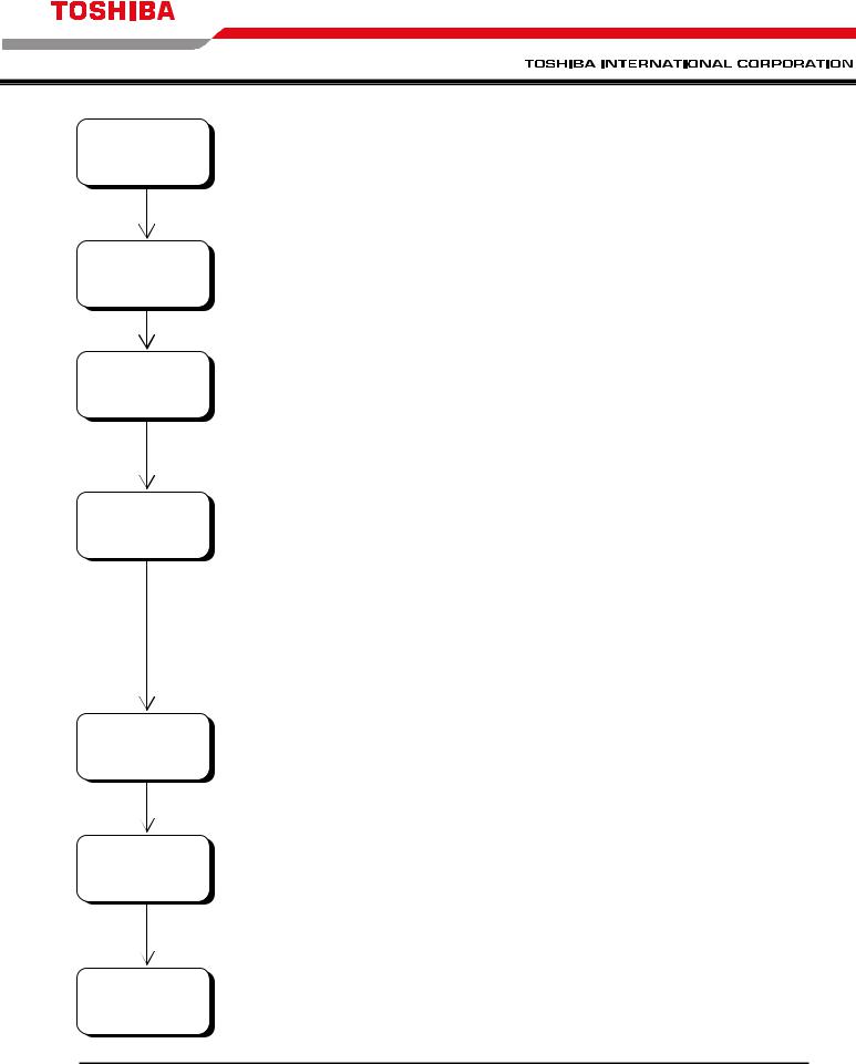
Preparations for Inspection and Maintenance of Equipment (Powering-Off)
Stop the equipment
Main power
OFF
Control power OFF
Wait for DC bus discharge
Voltage check
Grounding
1)Stop the equipment and check that the motor has completely stopped.
2)Press the interlock switch on the operation panel. The light on the switch should turn on.
3)Turn off the external main power supply. Disconnect and lockout the main power.
4)Turn off and lock out the control power supply.
5)Turn off an lock out any other job specific power feeding the drive.
5) Wait for 15 minutes or more for the bus to discharge.
6)Verify that all power is removed by measuring the main, the DC bus, the control, and any other external source voltage levels with properly rated measuring equipment.
Note! A meter rated for 5kV is required to safely check the main circuit voltages.
7)Ground the 3-phase input power supply terminal at the main circuit input terminals. (Grounding is automatic when the equipment is supplied with a JK type incoming starter.)
Work |
8) Perform the necessary maintenance. |
|
- 8
 Loading...