


LS-B110W
INSTRUCTION MANUAL
LASER SENSOR
LS-B110/LS-B110W
Thank you for purchasing the TOPCON LS-B110/LS-B110W.
For the best performance of the instruments, please read these instructions
carefully and keep them in a convenient location for future reference.
GENERAL HANDLING PRECAUTIONS
Before starting work or operation, be sure to check that the system is
functioning properly. Remove the batteries from the instrument when
you will not be using it for long period. When washing the instrument,
avoid spraying it with a high pressure stream of water from a water
hose. The inside of the instrument will be damaged by the water. This
instrument is designed based on the International Standard IPX 6, but it
is not protected from a high pressure water stream or submergence.
Affection of the radio waves
When using the instrument in the following place, the strong radio wave
may cause faulty operation.
• Near the instrument occurring strong radio waves. (e.g. Transceiver)
• Near the radio wave towers such as television or radio.
DISPLAY FOR SAFE USE
In order to encourage the safe use of products and prevent any danger to
the operator and others or damage to properties, important warnings are
put on the products and inserted in the instruction manuals.
We suggest that everyone understand the meaning of the following displays
and icons before reading the “Safety Cautions” and text.
Display Meaning
WARNING
CAUTION
• Injury refers to hurt, burn, electric shock, etc.
• Physical damage refers to extensive damage to buildings or equipment and furniture.
HANDLING PRECAUTIONS
Guarding the instrument against shock
When transporting the instrument, provide some protection to minimize risk
of shock. Heavy shock may affect beam accuracy.
SAFETY CAUTIONS
Ignoring or disregard of this display may lead to death or serious
injury.
Ignoring or disregard of this display may lead to personal injury
or physical damage to the instrument.
Standard Set Composition
1 LS-B110/LS-B110W Instrument .............................. 1pc.
2 C-size dry cells........................................................ 4pcs.
3 Carrying case .......................................................... 1pc.
4 Instruction manual................................................... 1pc.
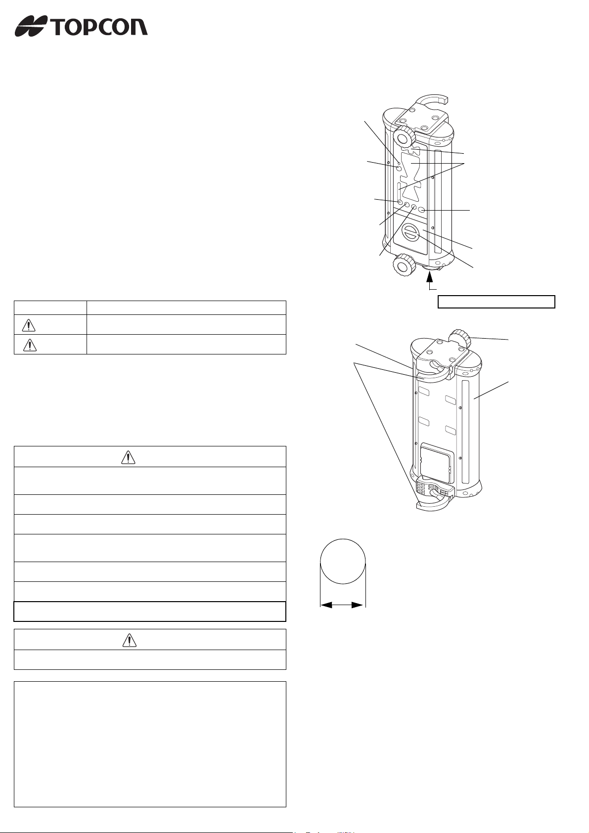
Nomenclature and Functions
Wireless communication LED
(For the LS-B110W
only)
Wireless communication switch
(For the LS-B110W
only)
Detective precision
(Mode) switch
Zero-set switch
Tilt switch
Detector
Clamp
Tilt indicator
Indicator
Please refer to the back of the
instruction manual for the
indicator display patterns.
Power switch
Power ON: Short push
Power OFF: Long push
Battery cover
Battery cover knob
Connector for external communication
Remove battery when connecting.
Clamp knob
Detector
WARNING
• There is a risk of fire, electric shock or physical harm if you attempt to disassemble or repair the instrument yourself.
This is only to be carried out by TOPCON or an authorized dealer, only!
• Risk of fire or electric shock.
Do not use damaged power cable, plug and socket.
• Risk of fire or electric shock.
Do not use a wet battery.
• May ignite explosively.
Never use an instrument near flammable gas, liquid matter, and do not use in a coal
mine.
• Battery can cause explosion or injury.
Do not dispose in fire or heat.
• The short circuit of a battery can cause a fire.
Do not short circuit battery when storing it.
• Battery can cause explosion or injury.
Remove battery when using the connector for external communication.
CAUTION
Do not allow skin or clothing to come into contact with acid from the batteries, if this
does occur then wash off with copious amounts of water and seek medical advice.
EXCEPTIONS FROM RESPONSIBILITY
1) The user of this product is expected to follow all operating instructions and make periodic checks
of the product’s performance.
2) The manufacturer, or its representatives, assumes no responsibility for results of a faulty or
intentional usage or misuse including any direct, indirect, consequential damage, and loss of
profits.
3) The manufacturer, or its representatives, assumes no responsibility for consequential damage,
and loss of profits by any disaster, (an earthquake, storms, floods etc.).
A fire, accident, or an act of a third party and/or a usage any other usual conditions.
4) The manufacturer, or its representatives, assumes no responsibility for any damage, and loss of
profits due to a change of data, loss of data, an interruption of business etc., caused by using the
product or an unusable product.
5) The manufacturer, or its representatives, assumes no responsibility for any damage, and loss of
profits caused by usage except for explained in the user manual.
6) The manufacturer, or its representatives, assumes no responsibility for damage caused by
wrong movement, or action due to connecting with other products.
Pipes that can be installed onto the LS-B110/LS-B110W are as described
below.
Shape: Cylindrical
Dimension: 45 to 51mm in diameter
Please refer to the instruction manual for the machine or
contact the machine manufacturer for instructions on install-
45 to 51mm
ing the mast onto the machine (by welding, etc.).
Operation
1 Position a rotating laser and turn on the laser.
2 Raise or lower the machine blade or arm to position the cutting
edge or bucket at the desired grade elevation.
3 Mount the LS-B110/LS-B110W onto the mast near the path of the
laser beam and turn on the LS-B110/LS-B110W.
4 Keep the machine blade or arm motionless and raise or lower the
LS-B110/LS-B110W and adjust until ON-GRADE position are flashing. This is the ON GRADE position.
5 Securely clamp the LS-B110/LS-B110W in place. The reference
position has been set.
6 While operating, use the LED display to continually check grade,
moving the blade or cutting / filling according to the direction of the
LS-B110/LS-B110W display.

Indicator
Precision mode
Mode1
Mode2
Mode3
Mode4
It is possible to change the detective precision of the
instrument.
Please select Mode 1 to 4 according to the objective of the
operation.
Pressing the detective precision (Mode) switch will change
the mode and the corresponding LED lamp will light up.
(During battery remaining display shown below, the lamp
will flash.)
Connector for external communication
The LS-B110/LS-B110W can be used as the laser detecting sensor for any TOPCON machine control system by connecting the communication cable to the connector for external communication. (Please contact your sales agent for details.)
Connecting the connector cable PC-18 (sold separately) to the connector for
external communication will enable the use of the LS-B110/LS-B110W from an
external power supply. When the instrument is operated with the external power
supply, the power-save and the auto-cut off functions will be invalidated. The LSB110/LS-B110W will turn on when connection is made to external power supply.
The power switch of the instrument will not function when an external power supply is used. Wireless communication will not function when using external communication or an external power supply.
LS-B110/LS-B110W Battery remaining display
Battery remaining display LED
Battery remaining for the LS-B110/LS-B110W will be displayed
at 3 levels.
Goes out:
Battery is sufficient. (When Mode 1 is selected, the lamp will
light up.)
Flashes slowly:
The power is low, but sensor is still usable.
Flashes quickly:
Dead battery. Replace the dry battery with new one.
Rotating laser battery warning display
Rotating laser battery
remaining warning LED
A flash shows that the rotating laser power is low.
(This function is not usable to the rotating laser which does
not have the function to output alarm signal.)
Laser beam positions and display patterns
Indicator (LED)
Detective precision
Mode1: ±3mm
Mode2: ±6mm (0.019ft)
Mode3: ±15mm (0.049ft)
Mode4: ±30mm (0.098ft)
±15mm/±0.05ft
(30mm/0.1ft width)
±30mm/±0.1ft
(60mm/0.2ft width)
(0.009ft)
Height alert warning of rotating laser
A flash signifies that the height alert function of rotating
laser is operating.
(This function is not usable to the rotating laser which does
not have the height alert and the function to output alarm
signal.)
Flashes
Power-save function
Flashes
The instrument turns the power-save mode after detecting
no laser beam for more than approx. five minutes.
During the power-save mode, LED (1 yellow, 1 red) will
flash.
(The mode is canceled automatically when the instrument
detects a laser beam again. The mode can also be canceled by pressing the power switch again.)
Flashes quickly
Flashes slowly
Flashes quickly
Flashes slowly
±50mm/±0.16ft
(100mm/0.33ft width)
±70mm/±0.23ft
(140mm/0.46ft width)
±125mm/±0.41ft
(250mm/0.82ft width)
Auto-cut off function
The power will be turned off automatically after detecting no laser beam for
more than approx. 60 minutes.
(To turn on the laser sensor, press the power switch again.)
* When turning the power on by pressing the power switch for more than
5 seconds, the power-save and the auto-cut off functions may be invalidated.
Flashes more slowly
When the laser
beam is off to the top
or to the bottom
 Loading...