


QUICK MANUAL
LCD Computerized Chart
CC-100 Series
REV. 10 2012

NOTE
Selecting externally connected equipment
The CC-100 Series Computerized chart complies with European Medical Device Directive and bears the CE marking.
Before connecting a external device to the CC-100 Series product make sure that such external equipment is in compliance with EN 60950-1 and CE marking.
This manual is referred to device with 3.4.x software version.
Manufacturer
VISIA imaging S.r.l. Via C. E. Gadda, 15
52027 San Giovanni Valdarno (AR) Italy
Distributor
Topcon Europe Medical B.V. Essebaan 11
2908 LJ Capelle a/d IJssel The Netherlands www.topcon.eu medical@topcon.eu
2

INTENDED USE
Utilisation
The CC-100 Series device is a instrument for the analysis of visual acuity.
The CC-100 Series device is able to execute the principal and most important visual tests: acuity, binocular vision, contrast sensitivity, and more.
The entire display screen is capable to display standard visual acuity tests and dissociated tests too.
The instrument display is commanded through an infrared remote control or through a direct connection with Topcon automated phoropters.
In comparison to the classical chart projectors, the PC functions allows for greater flexibility and more advanced functions.
Users
Oculists, ophthalmologists, opticians, optometrists.
The device must be uses by qualified personal.
Type of Environment where it could be use in
Ambulatory, physicians studios, opticians shops.
3
PRECAUTIONS
This instrument is an electronic precision unit, so be sure to use and store it in a place controlled under normal living temperature, humidity and atmospheric pressure, and avoid direct exposure to sunlight.
To ensure right operation, install the instrument on the wall and check for a precise horizontal and vertical alignment. Also do not put anything on top of the instrument.
To ensure an optimal coverage of polarized tests, align the center of LCD with the line of sight of the patient. Wear the polarized or Red/Green lenses and select in CC-100 Series a dissociated test, check the horizontal and vertical alignment until the best coverage for each eye is reached.
Connect all cables properly before using.
Use the power at a rated voltage.
When not in use, switch off the power source and protect the unit from sunlight and dust.
For accurate functioning, keep the instrument clean and free of spots and dust.
Technical Specifications :
Trade mark CE
93-42 EC Directive
Classification
IEC 601-1 Classification
Electrical Specifications:
Power Supply |
AC 110-120 V or 220-240V -- 50-60 Hz |
Power Absorption |
120VA |
Fuses |
220-240 V: 20x5mm 2.5A Antisurge |
|
|
|
|
Electromagnetic Compatibility
This product conforms to the EMC standard (IEC 60601-1-2:2007).
MEDICAL ELECTRICAL EQUIPMENT needs special precautions regarding EMC and need to be installed and put into service according to the EMC information provided in the accompanying documents.
Portable and mobile RF communications equipment can effect medical electrical equipment
The use of accessories and cables other than those supplied with the instrument, exception for cables sold by the manufacturer of the equipment as replacement parts, may result in increase emission or decrease immunity of the equipment or system.
The equipment or system should not be used adjacent to or stacked with other equipment. If adjacent or stacked use is necessary, the equipment or system should be observed to verify normal operation in the configuration in which it will be used.
4

EMC Table
Emission Guidance
The CC-100 SERIE is intended for use in the electromagnetic environment specified below. The costumer or the user of the CC-100 SERIE should assure that it is used in such an environment.
|
Emission Test |
|
|
Compliance |
|
|
Electromagnetic enviroment guide |
|
|
|
|
|
|
|
|
|
|
|
RF Emission |
|
|
Group 1 |
|
|
The CC-100 SERIE device uses RF energy only for |
|
|
|
|
|
|
|
its internal function. Therefore, its RF emissions |
|
|
|
|
|
|
|
|
|
|
|
|
Cispr 11 |
|
|
|
|
|
are very low and are not likely to cause any |
|
|
|
|
|
|
|
|
interference in nearby electronic equipment. |
|
|
|
|
|
|
|
|
|
|
|
RF Emission |
|
|
Class B |
|
|
The CC-100 SERIE device is suitable for use in all |
|
|
|
|
|
|
|
|
||
|
|
|
|
|
|
establishments, except for domestic |
|
|
|
|
|
|
|
|
|
|
|
|
Cispr 11 |
|
|
|
|
|
establishments and those directly connected to |
|
|
|
|
|
|
|
the public low-voltage power supply network that |
|
|
|
|
|
|
|
|
|
|
|
|
|
|
|
|
|
|
supplies buildings used to domestic purposes. |
|
|
|
|
|
|
|
|
It is possible to use the device in all |
|
|
|
|
|
|
|
|
establishments, including domestic |
|
|
|
|
|
|
|
|
establishments and those directly connected to |
|
|
|
|
|
|
|
|
the public low-voltage power supply network that |
|
|
|
|
|
|
|
|
supplies buildings used for domestic purposes. |
|
|
|
|
|
|
|
|
|
|
|
Harmonic Emission |
|
|
Class A |
|
|
It is possible to use the device in all |
|
|
|
|
|
|
establishments, including domestic |
|
||
|
|
|
|
|
|
|
|
|
|
IEC 61000-3-2 |
|
|
Compliant |
|
|
establishments and those directly connected to |
|
|
|
|
|
|
the public low-voltage power supply network that |
|
||
|
|
|
|
|
|
|
|
|
|
|
|
|
|
|
|
supplies buildings used for |
|
|
|
|
|
|
|
|
domestic purposes |
|
|
Voltage Fluctuation/flicker |
|
|
Compliant |
|
|
|
|
|
|
|
|
|
|
|
||
|
Emission |
|
|
|
|
|
|
|
|
IEC 61000-3-3 |
|
|
|
|
|
|
|
|
|
|
|
|
|
|
|
|
5

Immunity Guidance
The CC-100 SERIE device is intended for use in the electromagnetic environment specified below. The customer or the user of the device should assure that it is used in such an environment.
|
Immunity Test |
|
|
Test level |
|
|
Conformity Level |
|
|
Electromagnetic |
|
|
|
|
|
EN 60601-1-2 |
|
|
|
|
|
enviroment guide |
|
|
|
|
|
|
|
|
|
|
|
|
|
|
Electrostatic Discharge (ESD) |
|
|
8kV air |
|
|
8kV air |
|
|
Floors should be wood, |
|
|
|
|
|
|
|
|
|
|
|
|
|
|
EN 61000-4-2 |
|
|
6kV contact |
|
|
6kV contact |
|
|
concrete or ceramic tile. If |
|
|
|
|
|
|
|
|
|
|
|
floors are covered with |
|
|
|
|
|
|
|
|
|
|
|
synthetic material, the |
|
|
|
|
|
|
|
|
|
|
|
relative humidity should be at |
|
|
|
|
|
|
|
|
|
|
|
least 30 %. |
|
|
|
|
|
|
|
|
|
|
|
|
|
|
Electrical Fast Transient/Burst |
|
|
±2 kV high voltage |
|
|
±2 kV high voltage |
|
|
Mains power quality should |
|
|
EN 601000-4-4 |
|
|
power line |
|
|
power line |
|
|
be that of a typical |
|
|
|
|
|
|
|
|
|
|
|||
|
|
|
|
|
|
|
|
|
|
commercial or hospital |
|
|
|
|
|
|
|
|
|
|
|
environment. |
|
|
|
|
|
|
|
|
|
|
|
|
|
|
Surge EN 61000-4-5 |
|
|
Differential mode: |
|
|
Differential mode: |
|
|
|
|
|
|
|
|
|
|
|
|
|
|
|
|
|
|
|
|
1 kV |
|
|
1 kV |
|
|
Mains power quality should |
|
|
|
|
|
Common mode: |
|
|
Common mode: |
|
|
be that of a typical |
|
|
|
|
|
|
|
|
|
commercial or hospital |
|
||
|
|
|
|
|
|
|
|
|
|
|
|
|
|
|
|
2kV |
|
|
2kV |
|
|
environment. |
|
|
|
|
|
|
|
|
|
|
|
|
|
|
Voltage dips, short |
|
|
<5% UT |
|
|
<5% UT |
|
|
|
|
|
interruptions and voltage |
|
|
(>95% dip of UT) |
|
|
(>95% dip of UT) |
|
|
|
|
|
variations on power supply |
|
|
|
|
|
|
|
|
||
|
|
|
for 0,5 cycle |
|
|
for 0,5 cycle |
|
|
|
|
|
|
input lines |
|
|
|
|
|
|
|
|
||
|
|
|
|
|
|
|
|
|
Mains power quality should |
|
|
|
|
|
|
|
|
|
|
|
|
|
|
|
EN 61000-4-11 |
|
|
|
|
|
|
|
|
be that of a typical |
|
|
|
|
|
40% UT |
|
|
40% UT |
|
|
commercial or hospital |
|
|
|
|
|
(>60% dip of UT) |
|
|
(>60% dip of UT) |
|
|
environment. If the user of |
|
|
|
|
|
|
|
|
|
the device requires continued |
|
||
|
|
|
|
for 5 cycle |
|
|
for 5 cycle |
|
|
|
|
|
|
|
|
|
|
|
|
operation during power |
|
||
|
|
|
|
|
|
|
|
|
|
|
|
|
|
|
|
|
|
|
|
|
|
mains interruptions, it is |
|
|
|
|
|
70% UT |
|
|
70% UT |
|
|
recommended that the |
|
|
|
|
|
|
|
|
|
device be powered from an |
|
||
|
|
|
|
|
|
|
|
|
|
|
|
|
|
|
|
(>30% dip of UT) |
|
|
(>30% dip of UT) |
|
|
uninterruptible power supply |
|
|
|
|
|
for 25 cycle |
|
|
for 25 cycle |
|
|
or a battery. |
|
|
|
|
|
<5% UT |
|
|
<5% UT |
|
|
|
|
|
|
|
|
(>95% dip of UT) |
|
|
(>95% dip of UT) |
|
|
|
|
|
|
|
|
for 5 seconds |
|
|
for 5 seconds |
|
|
|
|
|
|
|
|
|
|
|
|
|
|
|
|
|
Magnetic field at power |
|
|
3 A /m |
|
|
3 A /m |
|
|
Magnetic power frequency |
|
|
frequency |
|
|
|
|
|
|
|
|
fields |
|
|
EN 61000-4-8 |
|
|
|
|
|
|
|
|
should be that of a typical |
|
|
|
|
|
|
|
|
|
|
commercial or hospital |
|
|
|
|
|
|
|
|
|
|
|
|
|
|
|
|
|
|
|
|
|
|
|
|
environment. |
|
|
|
|
|
|
|
|
|
|
|
|
|
6
Immunity Radio Frequency Guidance
The CC-100 SERIE is manufactured to work in the electromagnetic environment specified below. The operator or user should make sure it is use within those environmental conditions..
|
Immunity Test |
|
|
Test level |
|
|
Conformity Level |
|
|
Electromagnetic enviroment |
|
|
|
|
|
EN 60601-1-2 |
|
|
|
|
|
guide |
|
|
Conducted RF |
|
|
3 Veff from 150kHz to |
|
|
3 Veff from 150kHz to |
|
|
Portable and mobile RF |
|
|
|
|
|
|
|
|
communications equipment should |
|
|||
|
EN 61000-4-6 |
|
|
80MHz |
|
|
80MHz |
|
|
|
|
|
|
|
|
|
|
|
be used no closer to any part of the |
|
|||
|
|
|
|
|
|
|
|
|
|
|
|
|
|
|
|
|
|
|
|
|
|
device, including cables, than the |
|
|
|
|
|
|
|
|
|
|
|
|
|
|
Radiated RF |
|
|
3 V/m from 80MHz to |
|
|
3 V/m from 80MHz to |
|
|
recommended separation distance |
|
|
|
|
|
|
|
|
calculated from that equation |
|
|||
|
EN 61000-4-3 |
|
|
2.5GHz |
|
|
2.5GHz |
|
|
|
|
|
|
|
|
|
|
|
applicable to the frequency of the |
|
|||
|
|
|
|
|
|
|
|
|
|
|
|
|
|
|
|
|
|
|
|
|
|
transmitter. |
|
|
|
|
|
|
|
|
|
|
|
Recommended separation distance |
|
|
|
|
|
|
|
|
|
|
|
d = 1,2 √P from 150kHz to 80MHz |
|
|
|
|
|
|
|
|
|
|
|
d = 1,2 √P from 80 MHz to 800 |
|
|
|
|
|
|
|
|
|
|
|
MHz |
|
|
|
|
|
|
|
|
|
|
|
d = 2,3 √P from 800 MHz to 2,5 |
|
|
|
|
|
|
|
|
|
|
|
GHz |
|
|
|
|
|
|
|
|
|
|
|
where P is the maximum output |
|
|
|
|
|
|
|
|
|
|
|
power rating of the transmitter in |
|
|
|
|
|
|
|
|
|
|
|
watts (W) according to the |
|
|
|
|
|
|
|
|
|
|
|
transmitter manufacturer and d is |
|
|
|
|
|
|
|
|
|
|
|
the recommended separation |
|
|
|
|
|
|
|
|
|
|
|
distance in meters (m) |
|
|
|
|
|
|
|
|
|
|
|
|
|
The field intensity of the fixed RF transmitters, as checked in an electromagnetic investigation of the locus, should be less than the conformity level for each range of frequency. It is possible to have interference near devices marked with the symbol:
Recommended separation distances between portable and mobile RF communications equipment and the CC-100 XP device
CC-100 SERIE device is intended for use in an electromagnetic environment in which radiated RF disturbances are controlled. The customer or the user of the device can help prevent electromagnetic interference by maintaining a minimum distance between portable and mobile RF communications equipment (transmitters) and the device as recommended below, according to the maximum output power of the communications equipment.
|
Output maximum |
|
Separation distance at the transmitter frequency (m) |
||
|
nominal power of |
|
|
|
|
|
the transmitter (W) |
|
from 150kHz to 80MHz |
from 80MHz to 800MHz |
from 800MHz to 2GHz |
|
|
|
D= 1,2 x P |
D= 1,2 x P |
D= 2,3 x P |
0,01 |
|
0,12 |
0,12 |
0,23 |
|
0,1 |
|
0,38 |
0,38 |
0,73 |
|
1 |
|
1,2 |
1,2 |
2,3 |
|
10 |
|
3,8 |
3,8 |
7,3 |
|
100 |
|
12 |
12 |
23 |
|
For transmitters rated at a maximum output power not listed above, the recommended separation distance d in metres (m) can be determined using the equation applicable to the frequency of the transmitter, where P is the maximum output power rating of the transmitter in watts (W) according to the transmitter manufacturer.
Notes:
(1)At 80 MHz and 800 MHz, the separation distance for the higher frequency range applies.
(2)These guidelines may not apply in all situations. Electromagnetic propagation is affected by absorption and reflection from structures, objects and people.
7

Symbol Table:
8
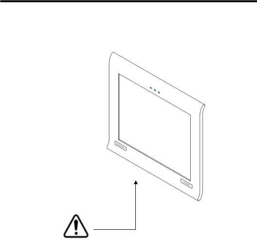
WARNING INDICATIONS AND POSITIONS
For safety purposes, this equipment includes clearly labelled warnings.
Use the equipment following this warning instructions.
CAUTION
To avoid electrical shock, do not open the instrument. Refer all servicing to only qualified personnel.
WARNING
Electrical shock may cause burns or possible fire. Turn the main power switch OFF and UNPLUG the power cord before replacing fuses. Replace only with fuses of the correct rating.
9
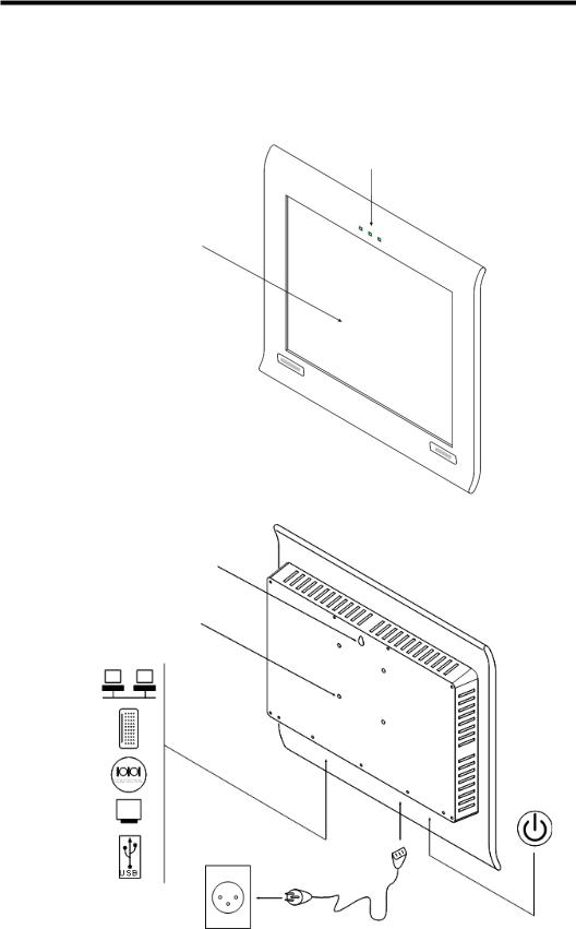
COMPONENTS
MAIN BODY COMPONENTS
I/R Sensor
Photo Sensor
Maddox Led
Test Area
Wall hook
Wallmounting screw holes
AC-3 pin
Power cable
10
CC-100 SERIES STANDARD ACCESSORIES
11
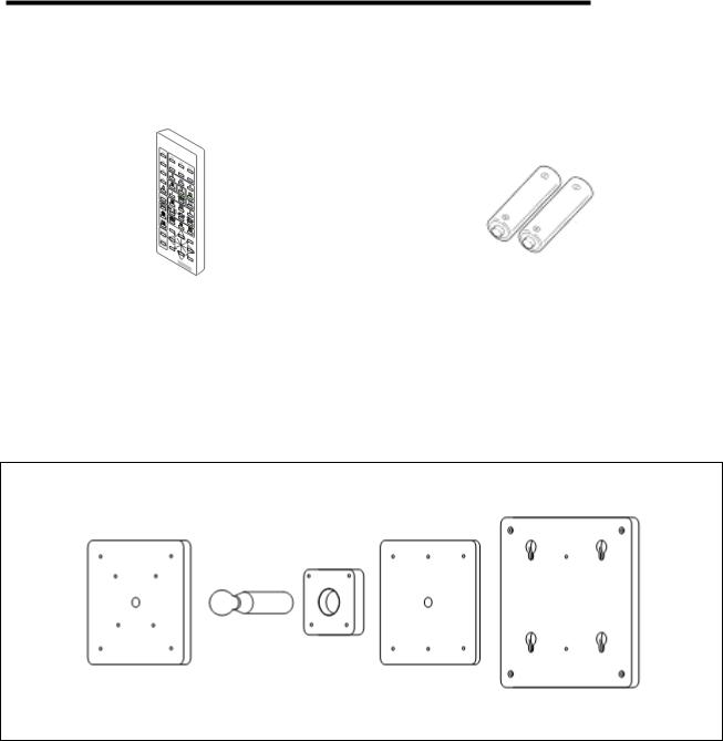
CC-SERIES OPTIONAL ACCESSESORIES
REMOTE CONTROL
Remote Control |
CC-Series Remote Control Batteries |
|
(AAA Type) |
||
(only for CC-100 Series instruments) |
||
|
||
|
|
CC-100 WALL MOUNTING
12
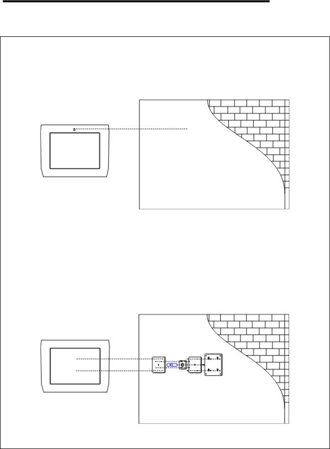
PREPARATIONS
WARNING: use appropriate screws and plugs to fix the unit to the wall.
Without WALL MOUNTING
With WALL MOUNTING
13
 Loading...