


CV-5000S installation manual (Ver.4)
TOPCON CORPORATION
July 2011

Index
1. |
Basic configuration................................................................................................................................................ |
2 |
|
2. |
Mounting the CV-5000S Phoropter head........................................................................................................... |
4 |
|
3. |
Connection of head/power supply and controller ............................................................................................. |
5 |
|
4. |
Installation of PC software (setup 3)................................................................................................................... |
7 |
|
5. |
Connection with chart ......................................................................................................................................... |
14 |
|
6. |
Connection with refraction instruments............................................................................................................ |
28 |
|
7. |
Output subjective data to PC............................................................................................................................. |
44 |
|
8. |
Network system 1................................................................................................................................................ |
52 |
|
9. |
Network system 2................................................................................................................................................ |
55 |
|
10. |
Network system 3.............................................................................................................................................. |
59 |
|
11. Network system 4.............................................................................................................................................. |
64 |
||
12. |
Network system 5.............................................................................................................................................. |
69 |
|
13. |
Network system 6.............................................................................................................................................. |
72 |
|
14. |
Details of setting menu..................................................................................................................................... |
77 |
|
15. |
Customizing pictures and movies (PC-50S only)......................................................................................... |
78 |
|
16. |
Export and import settings with USB memory .............................................................................................. |
80 |
|
17. |
Update KB-50S.................................................................................................................................................. |
81 |
|
1
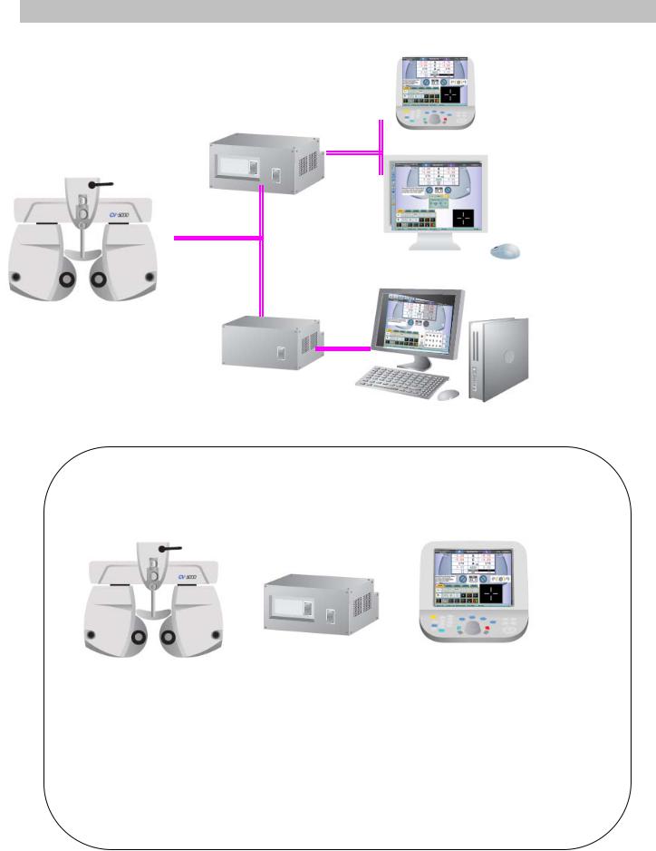
1. Basic configuration
SETUP 1 (KB-50S)
SETUP 2 (MONITOR & MOUSE)
SETUP 3 (PC)
SETUP 1 Basic components
2. 3.
1.
1.432239501 Phoropter head with arm
2.432249700 Power supply with built-in PC with built-in printer,
with measuring head connection cable and power cord.
3.432259500 KB-50S (one dial controller)
with USB/DC interface cable.
2
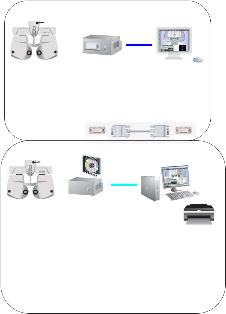
SETUP 2 Basic components
1. |
2. |
3. |
|
|
|
|
|
5. |
4.
1.432239501 |
Phoropter head with arm. |
|
|
|
2.432249700 |
Power supply with built-in PC |
Monitor |
||
with built-in printer, |
z |
analogue |
||
with measuring head connection cable and power cord. |
z |
VGA interface |
||
|
|
|
z 1024x768 resolution or more |
|
3. |
Monitor (locally arrange) |
|
|
|
4. |
USB mouse (locally arrange) |
|
|
|
5.VGA cable (locally arrange)
SETUP3 3 Basic component
1.
2. |
3. |
4. |
1.432239501 Phoropter head with arm.
2. 432249702 Power supply
with measuring head connection cable and power cord. (without printer)
with CV-5000PC software.
3.418120002 RS-232C serial cable (Din8 – Dsub9) (5m) or 424290061 RS-232C serial cable (Din8 – Dsub9) (10m) or RS-232C-USB conversion cable (locally arranged)
4.PC (locally arrange)
Monitor (DVI or VGA), USB mouse / Keyboard, Printer
3
PC requirements
Windows XP Professional SP3
Windows 7 Professional 32bit
Windows 7 Professional 64bit
In case of Internet Explorer Ver.8, a security patch file “KB2482017” should be installed.
91280x1024 resolution monitor
9At least one serial port.

2. Mounting the CV-5000S Phoropter head
See the instruction manual CV-5000S as well.
2-1. Level adjustment
2-2. Check the face shield and forehead rest.
2-3. Near point head and rod installation.
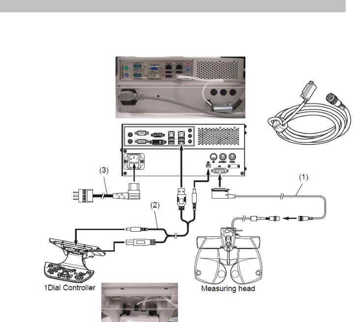
3. Connection of head/power supply and controller
3-1. SETUP 1
Connect power supply box, measuring head, KB-50S and power cord.
Measuring head connection cable
Power cord
KB-50S USB/DC interface cable.
5

3-2. SETUP 2
Connect power supply box, measuring head, analogue monitor, mouse, and power cord.
VGA cable
Power cord |
Measuring head connection cable |
3-3. SETUP 3
Connect power supply box, measuring head, PC and power cord.
RS-232C cable
Measuring head connection cable
Power cord
6
4. Installation of PC software (setup 3)
4-1. PC requirements
Windows XP Professional SP3 Windows 7 Professional 32bit Windows 7 Professional 64bit
* In case of Internet Explorer Ver.8, install Microsoft security update program “KB2482017”.
At least one serial port is necessary (to connect power supply box and PC), and make sure that COM port is recognized.
*Monitor resolution must be 1280 x 1024 or more.
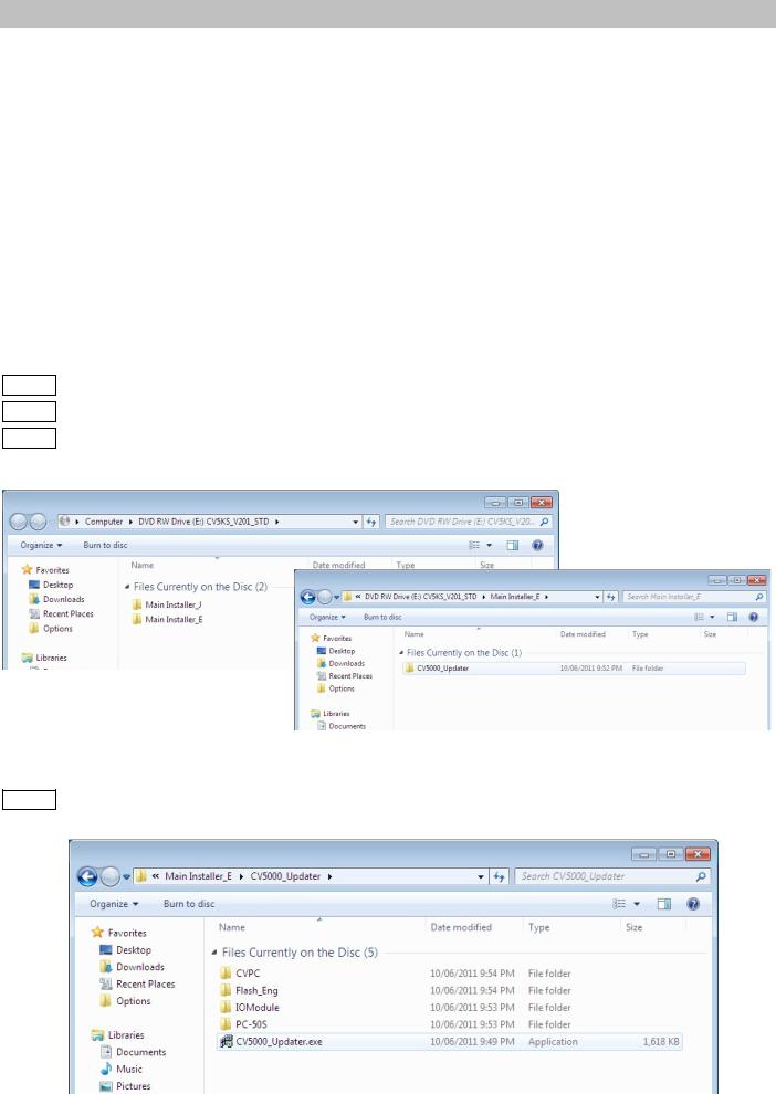
4-2. Install the software.
4-2.1. Turn on the PC
4-2.2. Insert the CV-5000 CD into CD/DVD drive of the PC. 4-2.3. Select [Main Installer_E] _ [CV5000_Updater]
4-2.4. Click [CV5000_Updater.exe].
7
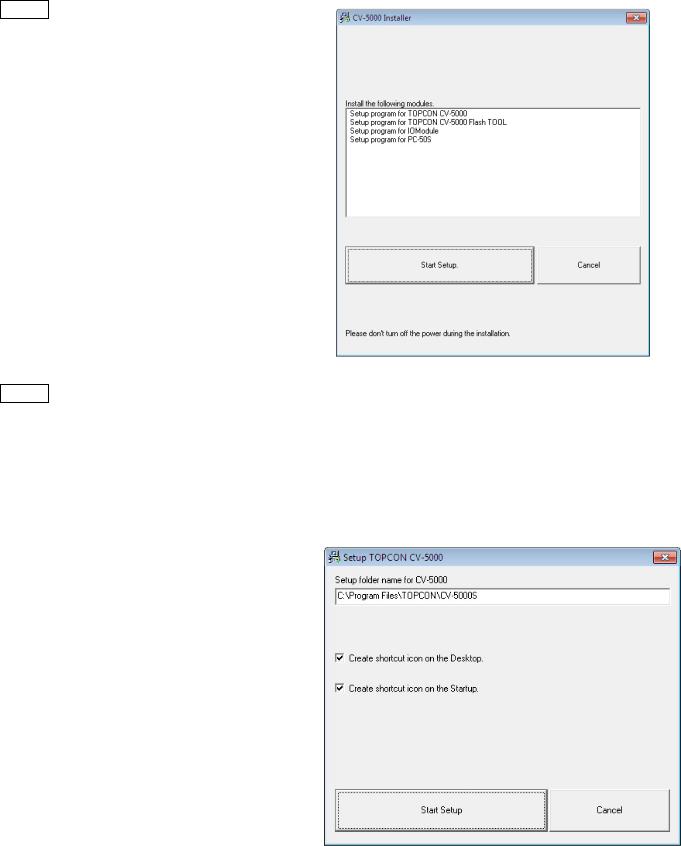
4-2.5. Click [Start Setup]
4-2.6. Check the installation destination folder.
(Default is C:¥ProgramFiles¥TOPCON¥CV-5000S)
Tick in [Create shortcut icon on the Desktop] Tick in [Create shortcut icon on the Startup]
Click [Start Setup].
8
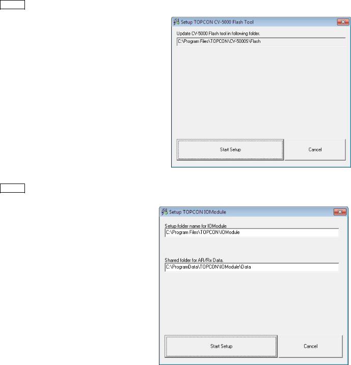
4-2.7. Click [Start Setup]
4-2.8. Click [Start Setup]
9
4-2.9. Click [Start Setup]
z Please wait if you find the “not responding”.
4-2.10.Click [OK] to finish installation.
10
4-3. Initial settings
4-3.1. Power up the power supply box and start [CV-5000PC]  software.
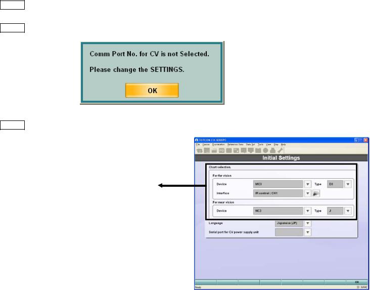
4-3.2. The following dialogue appears to check COM port. Click OK
4-3.3. In [Initial Settings], select followings.
[For Far Vision]
Device: the chart device to use.
ACP8, MC-3, PC-50, PC-50S or CC-100
Type: the chart type to use.
Chart type (A, B(M/F), C, D, F, H, IS)
Chart monitor selection: (in case of PC-50S)
Please select #: Plug and play monitor (=PC-50S)
Interface: (in case of ACP/MC/PC-50) 2 options of signal communication. -IR emitter
-RS232C
[For Near Vision]
Device: the chart device to use NC-3, NV20
Type: E/J
* Settings can be changed later, this process is necessary for start the software first time.
11
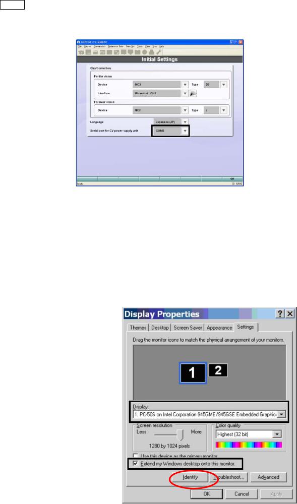
4-3.4. Select [serial port for CV power supply unit].
Select in the pull down menu, as there are COM numbers which are recognized are listed.
4-4. PC-50S setting.
In case of using PC-50S, adjust the display setting.
(1)Right click on the desktop, and select [Display Properties]
(2)Select [Settings]
(3)Select [Display]_[#:Plug and play monitor].
(4)Click [Identify] and make sure the selected number is displayed on PC-50S.
(5)Make sure the resolution is “1280x 1024” and 32 bit color.
(6)Tick in [Extend my Windows desktop onto this monitor].
(7)Click [OK]
12
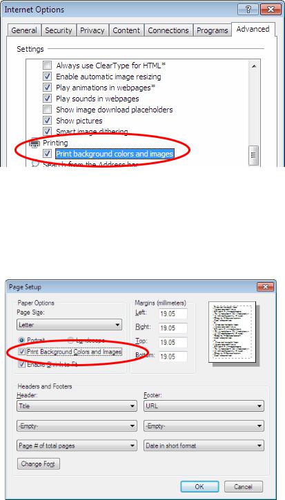
4-5. Printer setting
SETUP 3 does not have the built-in printer, thus please arrange a printer for PC if required.
The following is recommended to print setting to have report much clearer to see with highlights on title.
In case of Internet Explorer 6 / Internet Explorer 7.
select [Internet Explorer]_[Tools]_[Internet Options]_[Advanced] Tick in “Print background colors and images”.
In case of Internet Explorer 8,
select [Internet Explorer]_[Files]_[Page setup] *If the menu bar is hidden, press [Alt] key.
Tick in “ Print Background Colors and Images “.
13

5. Connection with chart
General information about cables
Wireless DVI
EZ AIR USB/DVI wireless doc http://www.ezairwireless.com/
424280001 DVI (10m)
432140006 (RS232C Din8-Din8) 5m
432140010 (RS232C Din8-Din8) 10m
418120002 (RS232C Din8 Dsub9) 5m
424290061 (RS232C Din8 Dsub9) 10m
424120005 IR emittor
Chart lineups
PC-50S : 424289700 ACP-8 series |
MC-3 |
PC-50 |
|
|
CC-100 series |
14

General layout of CV-5000S system and chart device
SETUP 1 or 2
SETUP 3
(1)EZAir wireless DVI
(2)424280001 DVI (10m)
SETUP 1, 2, or 3
(1) 

(2)
PC-50S
Exclusively in use with CV-5000S No remote controller is available
ACP-8 series
(1)
(2)
PC-50
CC-100 series
(1)ACP/MC-3 : 432140006 (RS232C Din8-Din8) PC-50 : 424290061 (RS232C Din8 Dsub9)
MC-3
(2) IR emittor 424120005
Remote controller is available (optional accessory)
Stand alone use is available
15

5-1. PC-50S for SETUP 1 and 2.
Please see Instruction Manual PC-50S for how to install PC-50S.
5-1.1. Cabling
Connect DVI cable to DVI socket of power supply.
DVI cable
5-1.2. Settings in CV-5000S
(1)When CV-5000S and PC-50S first time, the initial settings screen comes up.
For other cases,
(SETUP1) Press [Shift]&[Menu] button, and select [Settings]_[Chart Settings]
(SETUP2) Click [Settings]  icon and click [Chart Settings].
16
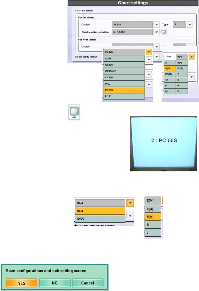
(2) Select “For far vision”, Device = PC-50S
Type = Chart A, B, E, F,H (at your convenience)
Chart Monitor Selection = #:PC-50S
(#: is automatically assigned)
z#:Plug and play monitor
stands for the monitor for control in Setup2.
(2)’ (Especially in SETUP2) Touch the mark, |
so that you can see the |
|
monitor for |
control #: plug and play monitor |
and #: PC-50S are |
recognized. |
|
|
|
(PC-50S displayÆ) |
|
(3) Select “For near vision”,
Device : NC3 or NV20 Type : E
(4)Touch [OK] 
(5)Touch [Yes]
17
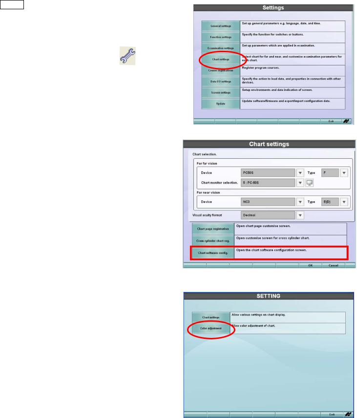
5-1.3. Settings in PC-50S.
(1)
(SETUP1) Press [Shift]&[Menu] button, and select
[Settings]_[Chart Settings]
(SETUP2) Click [Settings] |
icon and |
click [Chart Settings]. |
|
(2) Select [Chart Software Config.]
(3) Select [Chart Settings] .
18
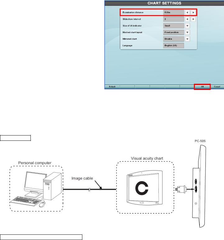
(4) Select each item.
*Examination distance(2.5m-6.0m) *slideshow interval (3-10 secs) *Size of VA indicator
*Masked chart layout *mirrored chart
*Language (no need to set)
(5) Touch OK 
5-2. PC-50S for SETUP 3
5-2.1. Cabling
Connect DVI cable between PC-50S and computer.
DVI cable
5-2.2. Settings in CV-5000S SETUP3
(1) Start CV-5000PC 
19
(2) Click [Settings]  and select [Chart Settings]
(3)Select in [For far vision],
Device = PC-50S
Type = Chart A, B, E, F,H
(at your convenience)
Chart monitor selection =
# : Plug and Play Monitor
Select in [For near vision]
Device = NC3/NV20
Type = E
Touch the mark, so that you can see # : Plug and Play Monitor
# : Plug and Play Monitor is recognized.
(PC-50S displayÆ)
20

5-2.3. PC-50S
See 5-1.3
5-3. PC-50S Wireless connection for SETUP 1&2, 3
EZ AIR USB/DVI wireless doc is only confirmed device. No other manufacturer’s cannot be used.
5-3.1. Connect USB transmitter to USB socket on control box (SETUP 1/2), KB-50S or on PC (SETUP3).
*Install USB driver for EZ Air in case of SETUP3. Control box (SETUP 1/2) is pre-installed with the driver for EZ Air.
5-3.2. Connect USB doc and PC-50S by DVI cable.
DVI cable
5-3.3. Select [#:Display Link Device].
21
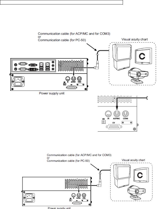
5-4. PC-50 / CC-100 series /ACP-8 / MC-3 (RS-232C)
Please see instruction manual for how to set up ACP-8/MC-3/PC-50.
5-4.1. Connect the chart to ACP/MC port of power supply with serial cable.
For ACP/MC-3 432140006 (RS232C Din8-Din8)
For PC-50 424290061 (RS232C Din8 Dsub9)
SETUP 1/2
SETUP 3
22
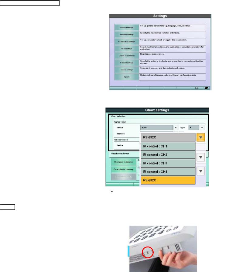
5-4.2. Settings in CV-5000S
(1)
(SETUP1) press [Shift]&[Menu], and select [Settings]_[Chart Settings]
(SETUP2,3) click [Settings ]  and select [Chart Settings]
(2) select each item in [For far vision] Device : ACP-8 or MC-3 or PC-50 Type : A, B, F, or H
Interface : RS-232C
5-4.3. in case of PC-50 (1)Turn on PC-50 power.
(2)Press Menu switch No.1 (left) to show [Main Menu].
23
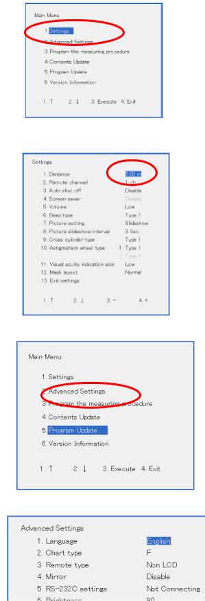
(3)[1. Settings]
(4) Set the distance.
(5)Exit and go to [2.select Advanced Settings].
(6)Select each necessary item.
24
 Loading...