


INSTRUCTION MANUAL
COMPUTERIZED LENSMETER
CL-100

INTRODUCTION
Thank you for purchasing the TOPCON
Computerized Lensmeter CL-100.
This Instruction Manual covers an overview of the TOPCON Computerized Lensmeter CL-100’s basic operations, troubleshooting, maintenance and cleaning.
To get the best usage from the instrument, please read the “Safety indications” and “Safety precautions”.
Keep this Manual within reach for future reference.
Precautions
•This is a precision instrument. It is expected that the instrument is used under normal room temperature and humidity condition.
•Install the instrument on a level, stabilized desk. Do not exposed to direct sunlight.
•Instrument must be kept clean at all times. Turn off and cover the instrument when it is not in use.
•For accurate measurements, make sure there is no dust or oil on the lens to be tested or on any portion in which the lens comes into contact with.
•Topcon is not responsible for any unauthorized disassembling and remodeling of the instrument.
•If the equipment is used in a manner other than that specified by the manufacturer, the warranty provided for the equipment may be impaired.
1

DISPLAY FOR SAFE USE
In order to encourage the safe use of this product, important warnings are put on the product and written in the instruction manual.
We suggest that everyone understands the meaning of the following displays and icons before reading the “Safety Cautions” and text.
DISPLAY |
MEANING |
CAUTION |
Ignoring this display may lead to personal |
injury or property damage. |
• Personal
injury refers to hurt, burn, electric shock, etc.
• Property damage refers to extensive damage to building or equipment and furniture.
ICONS |
MEANING |
|
This icon indicates a Hazard Warning. |
|
Specific content is expressed with words or an icon either |
|
inserted in the icon itself or located close to the icon |
SAFETY CAUTIONS
CAUTION
Icons |
Prevention item |
Page |
|
To prevent electrical shock, turn off the power switch and |
23 |
|
disconnect power cord before replacing fuses. |
|
|
Replace fuses with the same rating and type. |
|
2

USAGE AND MAINTENANCE
Usage:
The lensmeter is an electric equipment and the usage must be based on the Instruction Manual.
USER MAINTENANCE:
To maintain the safety and performance of the equipment, never attempt to do the maintenance of parts specified herein, which should be taken care of by our servicemen. The maintenance items that can be covered by users are the following; for details, follow the instructions.
Operating the fuse:
The fuse is replaceable.
For details, see page 23 of this manual.
ESCAPE CLAUSE
•TOPCON shall not take any responsibility for damages due to fire, earthquake, actions by third person, or the negligence and missuse by the user and used under unusual conditions.
•TOPCON shall not take any responsibility for damage derived from the inability to use this equipment, such as a loss of business profit and suspension of business.
•TOPCON shall not take any responsibility for damage caused by operations other than those described in this Instruction Manual.
WARNING INDICATIONS AND POSITIONS
To insure safety, warning labels are provided.
Use the equipment correctly by following the warning instructions. If any of the following labels are missing, please contact us at the address stated on the back cover.
3

CONTENT
INTRODUCTION |
1 |
DISPLAY FOR SAFE USE |
2 |
SAFETY PRECAUTIONS |
2 |
USAGE AND MAINTENANCE |
3 |
ESCAPE CLAUSE |
3 |
WARNING INDICATIONS AND |
3 |
POSITIONS |
|
COMPONENTS |
|
COMPONENT NAMES |
5 |
ACCESSORIES |
5 |
TV MONITOR |
|
MONITOR SCREEN |
6 |
MENU SCREEN |
8 |
MENU LIST |
9 |
USING THE INSTRUMENT |
|
PREPARATION |
10 |
SETTING THE PAPER |
10 |
(WITH - PRINTER TYPE) |
|
MEASURING |
11 |
AXIS MARKING |
19 |
PRINTING THE ADDITIONAL |
21 |
TEXTBOX (WITH - PRINTER TYPE) |
|
SETTING A SEQUENCE NO. |
22 |
ABBE COMPENSATION |
22 |
FUNCTION |
|
LENS PROTECTION PAD |
22 |
MAINTENANCE |
|
MAINTENANCE |
23 |
BEFORE REQUESTING |
|
SERVICE |
|
CAUTION MESSAGES |
25 |
CHECK ITEMS |
25 |
SPECIFICATIONS |
|
SPECIFICATIONS |
26 |
WITH - PRINTER TYPE |
26 |
OPTIONAL ACCESSORIES |
26 |
USING THE INSTRUMENT AS A SYSTEM
ON - LINE SYSTEM |
27 |
4
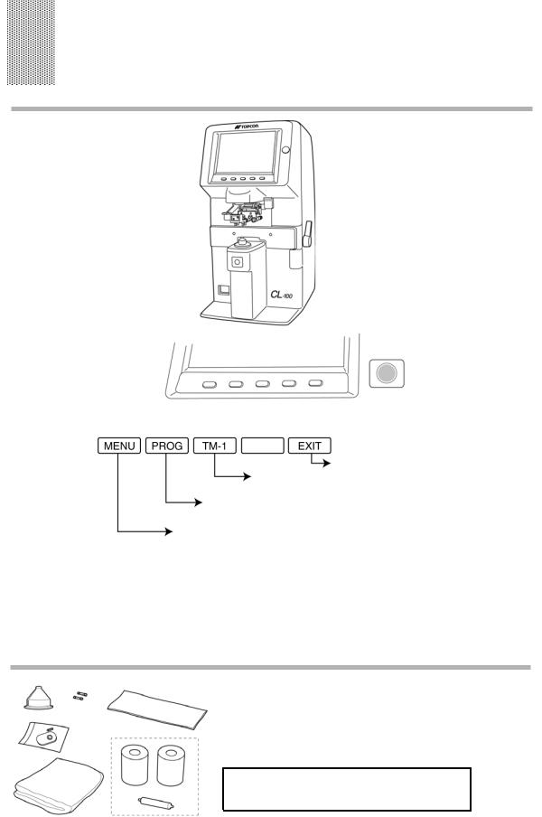
COMPONENTS
COMPONENT NAMES
TV Monitor |
|
|
|
|
|
|
|
|
|
BRIGHT control dial |
|
|
|
|
|
|
|
|
|
||
|
|
|
|
|
||||||
Lens retainer |
|
|
|
|
|
|
|
|
|
Axis marker lever |
|
|
|
|
|
|
|
|
|
||
|
|
|
|
|
|
|
|
|
|
|
|
|
|
|
|
|
|
|
|
|
|
Lens table |
|
|
|
|
|
|
|
|
|
Lens table lever |
|
|
|
|
|
|
|
|
|
||
Lens support |
|
|
|
|
|
|
|
|
|
|
|
|
|
|
|
|
|
|
|
||
|
|
|
|
|
||||||
MEMORY button |
|
|
|
|
|
|
|
|
|
|
|
|
|
|
|
|
|
|
|
|
|
Power supply |
|
|
|
|
|
|
|
|
|
|
|
|
|
|
|
|
|
|
|
|
|
|
|
(1) |
|
|
(2) |
|
(3) |
|
(4) |
|
(5) |
|
|
(6) |
|
|
|
|
|
|
|
|
|
|
|
|
|
|
|
|
|
|
|
|
|
|
|
|
|
||||||||||
(1) |
Mode buttons |
|
Pressed to change the mode, and when pressed; |
|||||||||||||
|
|
|
|
|
|
|
|
|
|
|
|
|
Returns to the initial state. |
|||
|
|
|
|
|
|
|
|
Pressed on to connect the spectral transmittance |
||||||||
|
|
|
|
|
|
|
|
meter (optional). |
|
|
||||||
|
|
|
if a progressive lens is known, this begins the far vision |
|||||||||||||
|
|
|
power measurement. |
|
|
|||||||||||
|
|
brings the Menu screen. |
|
|
|
|
|
|||||||||
(2) |
TRANS button |
|
|
Used to change (+) to (−) and vice versa in displayed cylinder |
||||||||||||
|
|
|
|
value. |
|
|
|
|
|
|
|
|
|
|||
(3) |
R/L button |
|
|
Used to designate R for right lens or L for left lens. |
||||||||||||
(4) |
CLEAR button |
|
|
Used to delete memory data. |
|
|
||||||||||
(5) |
PRINT button |
|
|
Press to output RC-232C data. |
|
|
||||||||||
|
|
|
|
Press to print out the measurement data. (with printer-type) |
||||||||||||
(6) MEMORY button ● Used to store the measurement data.
ACCESSORIES
(A) |
(A) Contact lens support |
.....................1 set |
(E) |
(B) Lens protection pad....................... |
1 set |
(D) |
(C) Dust cover ..................................... |
1 pc. |
(D) Silicon cloth ................................... |
1 pc. |
|
(B) |
(E) Fuse............................................. |
2 pcs. |
(C)
(F)
(G)
WITH-PRINTER TYPE |
|
(F) Printer paper ................................ |
2 rolls |
(G) Printer paper shaft ........................ |
1 pc. |
5
COMPONENTS

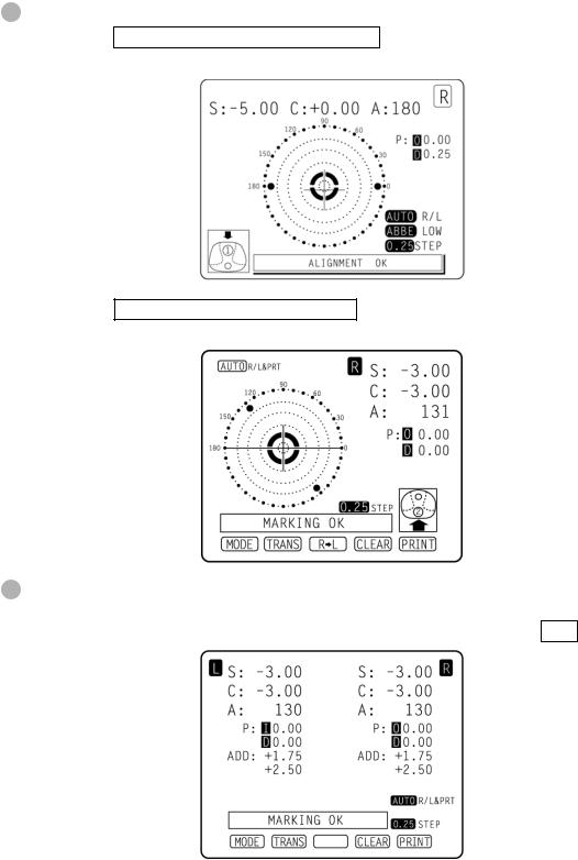
TV MONITOR
MONITOR SCREEN
Optical center’s off.
[OFF CENTER] is displayed when the optical center is off by 4∆ or more.
[ALIGNMENT OK] appears when the lens is ready for measurement.
Place + in center [MARKING OK] appears, and the lateral line will extend, getting the instrument ready for marking.
Left-eye lens
Transpose
Axial angle (every 5°)
OFF CENTER ERROR ALIGNMENT OK MARKING OK
HARD.C |
(HARD CONTACT) |
|
||||
SOFT.C |
(SOFT CONTACT) |
|
||||
PAD |
(LENS PROTECTION PAD) |
|
||||
|
|
|
|
|
|
|
|
|
Right-eye lens |
||||
|
|
(Inversion indicates a |
|
|
||
|
|
storage status.) |
|
|
||
|
|
|
|
|
|
|
|
|
|
|
|
|
|
|
|
AUTO R/L on status |
||||
|
|
(auto memory and auto R/L |
||||
|
|
switching) |
||||
|
|
When AUTO is displayed |
||||
|
|
inversion, R/L is automemory |
||||
|
|
off. |
||||
|
|
AUTO PRINT waiting status |
||||
|
|
|
|
|
|
|
|
|
|
|
|
|
|
|
|
When a high-refraction |
||||
|
|
lens diopter is |
|
|
|
|
|
|
compensated |
|
|
|
|
|
|
|
|
|
|
|
|
|
|
|
|
|
|
|
|
Step |
||||
|
|
|
|
|
|
|
6
TV MONITOR
Enlargement:
When MENU/DISPLAY/HORIZONTAL LARGE is selected, the SCA display is horizontally enlarged to make it easier to see.
When MENU/DISPLAY/VERTICAL LARGE is selected, the SCA display is vertically enlarged to make it easier to see. The graphic moves to the opposite side.
Screen print display: (when enlaraged )
For framed lenses, of which both R and L are memorized, pressing the PRINT button enlarges the SCA of both eyes. To return to the original state, press the EXIT button.
7
TV MONITOR
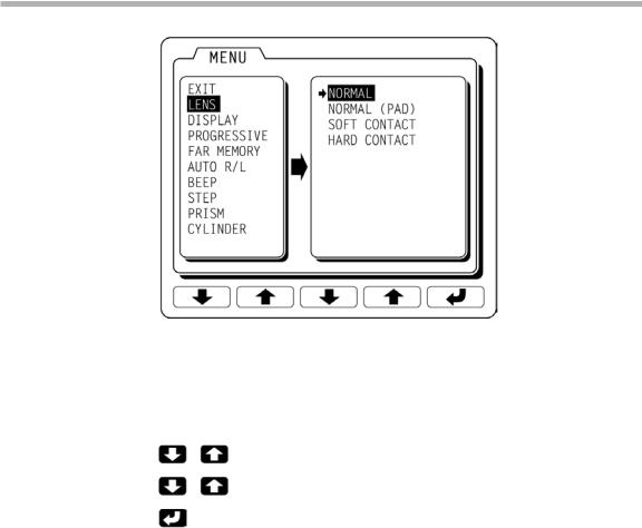
MENU SCREEN
To display the “MENU” screen, press the “MODE” button then the “MENU” button.
Icons will appear at the bottom of the screen. Refer to the buttons at the bottom of the screen to scroll through the Menu.
Selects a menu.
Selects the contents of each menu.
Changes the setting, and return to the measurement screen.
8
TV MONITOR
 Loading...