


KR-1
Table of contents
 Loading...
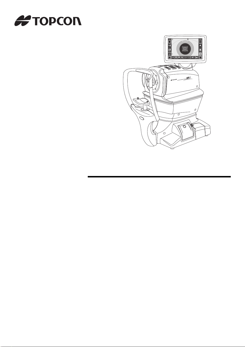
HIGH
FOG
12.00
01
VD
-1.2525
-0.5050
7.8 0
7.7 5
180
180
PR2
0000100001000
00001000010 00
00001000010 00
mm
R
S
C
A
K
R1
R2
A
PR1
1
MANUAL
7.80
0
1 0
R
S
C
A
K
R1
R2
A
PR1
PR2
PA1
PA1
ID
R L
-1.
-0.
180
R1
7.80
R2
7.75
180
PR1
7.80
01
R/K
0000100001000
MANUAL
R1
R2
PR2
PA1
mm
FOG
HIGH
PR1
PR2
PA1
VD
12.00
M
USER MANUAL
AUTO KERATO-REFRACTOMETER
KR-1


INTRODUCTION
Thank you for purchasing the TOPCON Auto Kerato-Refractometer KR-1.
INTENDED USE / INDICATIONS FOR USE
This instrument is used to measure the spherical refractive-power, cylindrical refractive power, the
direction of astig mat ic ax i s, the ra diu s of c urv atu re , th e c orneal astigmatic ax is an gle and the corneal refractory power.
FEATURES
This instrument features the following:
• The KR-1 is simple to operate and measures the refraction and corneal curvature of the eye.
• The position of the touch panel can be adjusted to accommodate the user's preferred position.
• The auto start function facilitates quick measurements under the optimal condition.
PURPOSE OF THIS MANUAL
This User Manual provides an overview of the basic operation, troubleshooting, checking, maintenance and
cleaning of the TOPCON Auto Kerato-Ref ractometer KR-1.
To get the best use of the instrument, read Safety Displays and Safety Cautions.
Keep this Manual at hand for future reference.
INTENDED PATIENT POPULATION
• The patient who undergoes an examination by this instrument must maintain concentration for a few minutes and keep to the following instructions:
To fix the face to the chinrest, forehead rest.
To keep the eye open.
To understand and follow instructions when undergoing an examination.
• Since this product is a precision instrument, always use and keep it in a normally controlled living environment, within a temperature range of 10-40°C, humidity levels between 30-90% and an atmospheric pressure range of 700hPa-1,060hPa.
The instrument should also be placed away from direct sunlight.
• To ensure smooth operation, install the instrument on a level floor free of vibrations. Also, do not place
anything on the instrument.
• Connect all cables properly before using.
• Use the power at a rated voltage.
• When not in use, switch off the power source and apply the rubber cap and dust cover.
• For accurate measureme nt res ul t s, take care to keep the measuring window cl ean and free of fingerpr int s ,
spots and dust.
[CAUTION] Federal law restricts this device to sale by or in the order of a Physician or Practitioner.
Since this product partly uses a program derived from IPA Font, using the product is regarded as consent to the IPA Font License
Agreement v1.0.
For the IPA Font License Agreement v1.0, see page 71 or the following URL.
http://ipafont.ipa.go.jp/ipa_font_license_v1.html
1

DISPOSAL
When disposing of the i nstrume nt and/or parts, fo llow loca l regulation s for dis posal and re cycling.
This product contains a CRL Lithium Battery which contains Perchlorate Material-special handling may apply.
See http://www.dtsc.ca.gov/hazardouswaste/perchlorate/
Note; This is applicable to California, U.S.A. only
STORAGE AND USAGE PERIOD
1. WHEN STORING THE INSTRUMENT, ENSURE THAT THE FOLLOWING CONDITIONS ARE MET:
(1) The instrument should not be splashed with water.
(2) Store the instrument away from envir onments where air pressure , temperature , humidity,
ventilation, sunlight, dust, salty/sulfurous air, etc. could cause damage.
(3) Do not store or trans port the instrument on a slanted or uneven su rface or in an area
where it is subject to vibrations or instability.
(4) Do not store the instrument where chemicals are stored or gas is generated.
2. NORMAL LIFE SPAN OF THE INSTRUMENT:
8 years from delivery providing regular maintenance is performed (according to the self-certification [Topcon data])
USER MAINTENANCE
1. Regularly measure the attached model eye and check the accuracy.
2. Clean the measuring window when it is soiled.
3. Clean the forehead rest and chinrest when these are soiled.
4. Put on the dust cover when not in use.
2

HOW TO READ THIS MANUAL
• Read the instructions on pages 1 to 8 before using the machine.
• Regarding connection to various devices, see "CONNECTING EXTERNAL I/O TERMINALS" on page 20.
• If you would like an overview of the system, begin by reading "BASIC OPERATIONS"(page
24).
• For setting various functions, see "SETTING FUNCTIONS ON SETUP SCREEN" on page
44.
SYMBOLS IN TEXT
MEMO: Useful functions to know and attentions to prevent troubles are noted.
3
DISPLAYS FOR SAFE USE
WARNING
CAUTION
In order to encourag e th e s afe us e of t he ins trum ent and to avoid dange r to t he opera t or an d o thers as well as dam age to prop erties, warnings are descr ibed in the User Manual and marked on
the instrument body.
We suggest you thor oughly understand the meaning of the following displays/icons and Safety
Cautions, as well as read the Manual, and strictly observe the instructions.
DISPLAYS
DISPLAY MEANING
Improper handling or ignori ng this display may lead to
the danger of death or serious injury.
Improper handling or ignoring this display may ca use
personal injury or physical damage.
• Injury means hurt, burn, electric shock, etc.
• Ph ysical d amage mea ns exten sive dama ge that ma y invol ve buil ding, pe ripheral equipment and furniture.
4
GENERAL SAFETY INFORMATION
WARNINGS
Ensuring the Safety of Patients and Operators
When operating the instrument, do not touch the patient's eye or nose.
Handling the cord o n this produ ct or cords ass ociated with a cces sories s old with th is pro duct,
will expose you to lead, a chemical kn own to the State of California to cause birth detects or
other reproductive harm. Wash hands after handling.
Preventing Electric Shocks and Fires
To avoid fire and electric shock, install the instrument in a dry place free of water and other liquids.
To avoid fire and electric shock, do not put cups or other containers with liquids near the instrument.
To avoid electr ic shoc ks, do not i nsert metal objects into the inst rumen t body thro ugh th e vent
holes or gaps.
To avoid fire in the event of an instrument malfunction, immediately turn OFF the power switch
" " and disconnect the p ower plug from the outlet i f you see smoke comi ng from the instrument, etc. Don't install the instrument where it is difficult to disconnect the power plug from the
outlet. Ask your dealer for service.
5
Ensuring the Safety of Patients and Operators
CAUTIONS
To avoid injury when operating the chinrest up/down button, be careful not to catch the
patient's fingers.
Preventing Electric Shocks and Fires
To avoid injury by electric shock, do not open the cover. For repair, call your service engineer.
To avoid inj ury by electric shock wh en changing the fuse, turn off the power and pull off the
power cable. Use the rated fuse.
Electromagnetic Compatibility (EMC)
This instrument has been test ed (with 100/120/230V) and found to comply with IEC60601-12:Ed.3.0:2007. This instrument radiates radio frequency energy within standard and may affect
other devices in the vicinity. If you have discovered that turning on/off the i nstrument affects
other devices, we recommend you change its position, keep a proper distance from other
devices, or plug it into a different out let. Please consult your au tho rize d dea le r if you hav e any
additional questions.
6

USAGE AND MAINTENANCE
Usage:
• Since the Auto Kerato-Refractometer KR-1 is medical device, the operation should be
supervised by a physician.
USER MAINTENANCE
To maintain the safety and performance of the equipment, never attempt to do maintena nce
except for the items specified below. For details, follow the instructions.
FUSE CHANGE
For details, See “FUSE CHANGE” on page 68.
CLEANING OF MEASURING WINDOW
For details, See “CLEANING THE INSTRUMENT” on page 65.
DISCLAIMERS
• TOPCON is not responsible for damage due to fire, earthquakes, actions or inactions of third
persons or other accid ents, or damage due to negligen ce and misuse by the us er and any
use under unusual condit io ns.
• TOPCON is not responsible for damage derived from in ability to properly use this equipment, such as loss of business profits and suspension of business.
• TOPCON is not responsible for damage caused by operations other than those described in
this User Manual.
• The devi ce doe s not p rovide a diagn osis of any c onditi on or la ck the reof o r any r ecomm endations for appropriate treatment. The relevant healthcare provider is fully responsible for all
diagnosis and treatment decisions and recommendations.
7
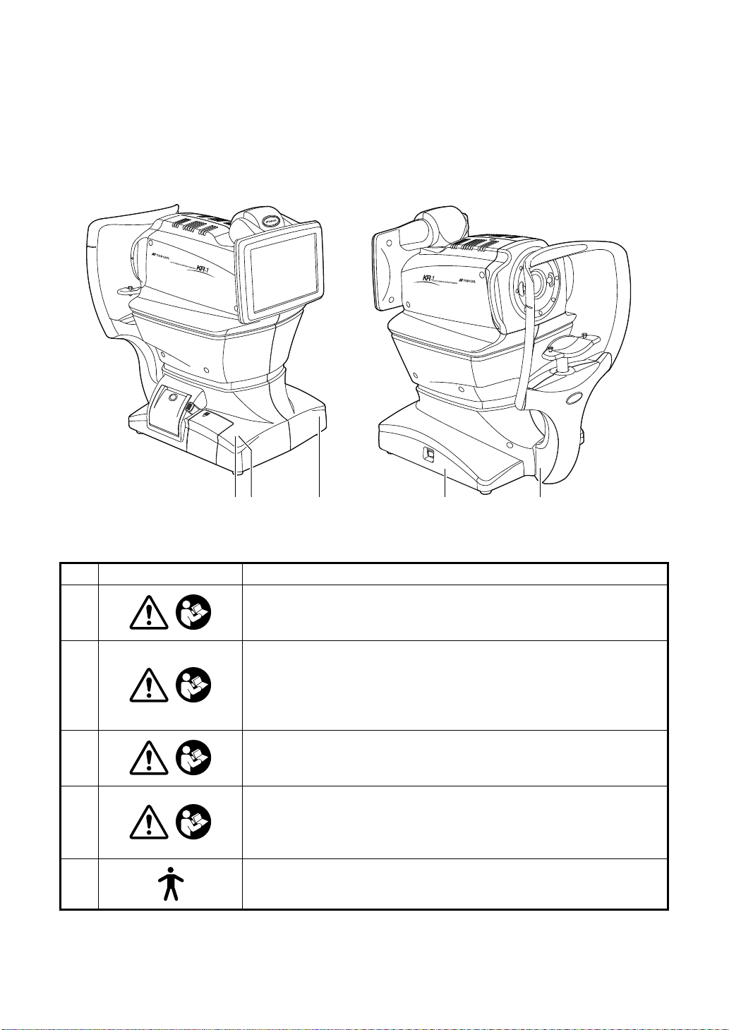
POSITIONS OF WARNING AND CAUTION
3 14 2 5
INDICATIONS
To secure safety, this equipment provides warnings.
Correctly use the equipment following these warning instructions. If any of the following marking labels are missi ng, please contact your dealer or TOPCON at the addres s stated on the
back cover.
No. Label Meaning
WARNING
1
2
3
4
5
To avoid injury caused by electric shock, do not open the cover.
Ask your dealer for service.
WARNING
Electric shock may cause burns or a possible fire.
Turn the power switch OFF and unplug the power cord before
replacing the fuses.
Replace only with fuses of the correct rating.
CAUTION
Be careful not to hit the patie nt's eyes or nose wit h the instr ument
during operation.
CAUTION
When operating the chinrest up/down switch, be careful not to
pinch the patient's hand.
The patient may be injured.
Degree of protection against electric shock:
TYPE B APPLIED PART
8

CONTENTS
INTRODUCTION ....................................................................................................1
HOW TO READ THIS MANUAL.............................................................................3
SYMBOLS IN TEXT ........................................... ...... ...... ..............................3
DISPLAYS FOR SAFE USE...................................................................................4
DISPLAYS....................................................................................................4
GENERAL SAFETY INFORMATION .....................................................................5
USAGE AND MAINTENANCE ...............................................................................7
USER MAINTENANCE...........................................................................................7
FUSE CHANGE............................................................................................7
CLEANING OF MEASURING WINDOW ............................................ ...... ....7
DISCLAIMERS .......................................................................................................7
POSITIONS OF WARNING AND CAUTION INDICATIONS..................................8
COMPONENTS
COMPONENT NAMES.........................................................................................11
COMPOSITION OF PARTS WHICH CONTACT THE HUMAN BODY................11
OPERATION METHOD OF CONTROL PANEL...................................................12
CONTROL PANEL COMPONENTS.....................................................................12
FUNCTION BUTTON .................................................................................13
MONITOR SCREEN.............................................................................................14
MEASUREMENT SCREEN........................................................................14
SETTINGS SCREEN..................................................................................14
CORNEA DIAMETER MEASUREMENT SCREEN....................................14
PRINTER OUTPUT ..............................................................................................15
PRINTOUT FORMAT SETTING ........................................... ...... ....... ...... ..17
STANDARD ACCESSORIES ...............................................................................18
PREPARATIONS
INSTALLATION ....................................................................................................19
CONNECTING POWER CABLE ..................... ...... ....... ...... ..................................19
CONNECTING EXTERNAL I/O TERMINALS ......................................................20
DATA OUTPUT ..........................................................................................20
DATA INPUT ..............................................................................................21
PRINTER PAPER SETTING ................................................................................21
RECOVERY FROM POWER SAVE STATUS......................................................23
ADJUSTING THE CONTROL PANEL POSITION................................................23
BASIC OPERATIONS
PREPARATION BEFORE MEASUREMENT .......................................................24
TURNING ON THE INSTRUMENT............................................................24
SELECTING THE MEASUREMENT MODE..............................................24
PATIENT POSITIONING............................................................................25
AUTO MODE MEASUREMENT...........................................................................27
SETTING THE AUTO MODE.....................................................................27
ALIGNMENT AND MEASUREMENT.........................................................28
DISPLAYING MEASUREMENT VALUES..................................................29
MANUAL MODE MEASUREMENT......................................................................30
SETTING THE MANUAL MODE................................................................30
ALIGNMENT AND MEASUREMENT.........................................................30
DISPLAYING MEASUREMENT VALUES..................................................33
PRINT-OUT OF MEASUREMENT VALUES........................................................34
CLEARING MEASUREMENT VALUES...............................................................35
DISPLAYING ALL MEASUREMENT DATA .........................................................36
OPERATION OF AFTER USE .............................................................................37
9

OPTIONAL OPERATIONS
DISPLAYING THE PATIENT ID (PATIENT No.) OR EXAMINER ID ...................38
MEASURING ONE EYE ONLY............................................................................38
MEASURING THE RIGHT EYE ONLY ......................................................38
MEASURING THE LEFT EYE ONLY.........................................................38
MEASUREMENT OF CORNEA DIAMETER........................................................39
MEASUREMENT ON THE ACTUAL IMAGE .............................................39
MEASUREMENT ON THE STILL IMAGE..................................................41
OUTPUT USING RS232C....................................................................................43
INPUT USING USB ............................ ...... ....... ...... ....... ...... ...... ....... .....................43
OUTPUT USING LAN...........................................................................................43
SETTING FUNCTIONS ON SETUP SCREEN
OPERATING THE SETUP SCREEN ...................................................................44
PREPARATONS FOR SETTING...............................................................44
OUTLINE OF SETUP SCREEN OPERATIONS ........................................45
RETURNING TO THE MEASUREMENT SCREEN...................................47
LIST OF SETUP ITEMS .......................................................................................48
INITIAL (INITIAL SETTING) .......................................................................48
SETTING OF INTERNAL PRINTER (PRINT) ............................................50
DATA COMMUNICATION (COMM) ...........................................................52
LAN CONNECTION (LAN).........................................................................53
OPERATOR ID...........................................................................................53
SPECIAL ....................................................................................................53
TROUBLESHOOTING
MESSAGE LIST .........................................................................................54
TROUBLE-SHOOTING OPERATIONS......................................................55
SPECIFICATIONS AND PERFORMANCE
SPECIFICATIONS AND PERFORMANCE ..........................................................56
ENVIRONMENTAL CONDITIONS OF USE...............................................57
ENVIRONMENTAL CONDITIONS OF STORAGE ....................................57
ENVIRONMENTAL CONDITIONS OF TRANSPORT................................57
ELECTROMAGNETIC COMPATIBILITY .............................................................58
ELECTRIC RATING . ...... ....... ...... ............................................. ............................62
SAFETY DESIGNATIONS PER IEC 60601-1 STANDARD .................................62
DIMENSIONS AND WEIGHT...............................................................................62
OPERATION AND PRINCIPLE OF OPERATION................................................63
REFERENCE
OPTIONAL ACCESSORIES.................................................................................64
SHAPE OF PLUG.................................................................................................64
SYMBOL...............................................................................................................64
MAINTENANCE
DAILY CHECKUPS ..............................................................................................65
CHECKING THE MEASURING ACCURACY ............................................65
CLEANING THE INSTRUMENT ................................................................65
CLEANING THE FOREHEAD REST AND CHIN REST ............................65
DAILY MAINTENANCE.................. ....... ...... ....... ...... ...... ....... ...... ....... ...... ..66
ORDERING CONSUMABLE ITEMS..........................................................66
USER MAINTENANCE ITEM.....................................................................66
BRIGHTNESS ADJUSTMENT OF CONTROL PANEL..............................67
PRINTER PAPER JAM ............................................ ...... ....... ...... ....... ........67
FUSE CHANGE..........................................................................................68
SUPPLYING THE CHINREST TISSUE .....................................................69
MAINTENANCE....................................................................................................70
CLEANING THE COVER ...........................................................................70
CLEANING THE CONTROL PANEL..........................................................70
10
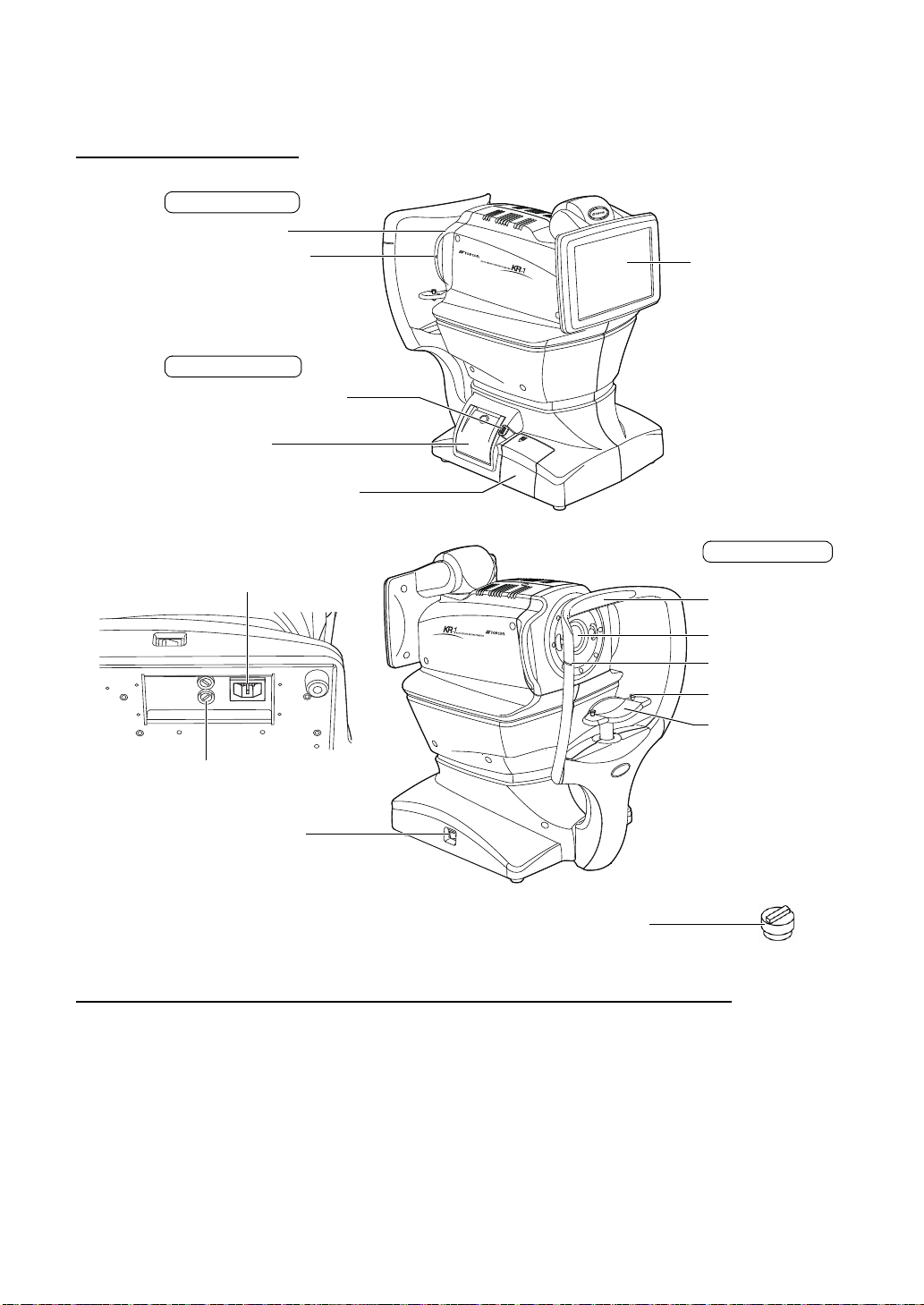
COMPONENTS
Control panel
Eye height mark of
measuring window
POWER switch
Forehead rest
Measuring window
Eye height mark
Chinrest tissue pin
Chinrest
Main body Section
Chinrest Section
Power unit Section
Printer cover open switch
Printer cover
External I/O terminal cover
Rubber cap
Measuring head
Power inlet
Fuse folder
*1
*1: Contacting part (class B)
*1
COMPONENT NAMES
COMPOSITION OF PARTS WHICH CONTACT THE HUMAN BODY
Forehead rest : Silicone rubber
Chinrest : Acrylonitrile butadiene styrene resin
11
COMPONENTS
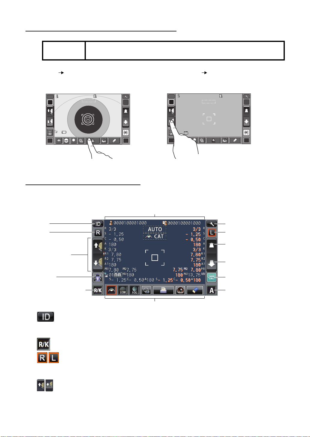
OPERATION METHOD OF CONTROL PANEL
R L
R/K
ID
A
13.7513.75
-1.-1 .2525
-0.-0 .5050
7.807. 80
7.807. 80
7.757. 75
18018 0
18018 0
010 1
VDVD
PR2PR2
0000100001000000010 0001000 00001000010000 000100001000
mmmm
R
S
C
A
K
R1
R1
R2R2
A1A1
PR1PR1
3/33/3
3/33/3
AUTOAUTO 0/30/3
0/30/3
R
S
C
A
K
R1
R1
R2R2
A1A1
PR1PR1
PR2PR2
PA1PA1
PA1PA1
LOWLOW
FOGFOG
R L
R/K
00001000010000100001000010 00010000100 001 0000100001000010 0001
13.7513.75
diodio
AUTOAUTO
010 1
VDVD
S
ID
A
mmmm
R
S
C
A
K
R1R1
R2R2
A1A1
PR1PR1
PR2PR2
PA1PA1
PR2PR2
PA1PA1
R
S
C
A
K
R1R1
R2R2
A1A1
PR1PR1
HIGHHIGH
FOGFOG
0/30/3
0/30/3
0/30/3
0/30/3
Settings button
Display
L button
Measuring head forward
button
Measuring head backward button
Start button
Auto/Manual button
Function button
ID button
R button
Up/down button for
chinrest
Reset button
Measurement mode button
NOTE:
The control panel is a touch panel. Do not use a ny sharp too ls; e.g. ba ll
point pen.
Tap To select any relevant item. Continue to press Used for continuous moving.
(Moving of chinrest and
measuring head)
Touch the screen softly with a finger. Continue to touch the screen softly with a finger.
CONTROL PANEL COMPONENTS
The control panel is designed as a touch panel for performing various operations and settings.
It displays images and shows information, including set conditions and measurement results.
ID button ........................... .....Input the patient ID (up to 13 characters) and operator
Measurement mode button...... Selects a measurement mode from REF, KRT and R/K.
12
COMPONENTS
R button/L button................. Selects the right/left eye. By tapping the button, the
Up/down button for chinrest ... Moves the chinrest up/down.
ID (up to 21 characters). However, if no patient ID is
input, the patient No. is allocated automatically.
main body moves to the selected direction.
The selected button is framed in orange.
Reset button ............................ Returns the chinrest and measu ring head to the initial
Cataract button
ALL CLEAR button
Cornea diameter buttonFixation target button
Print out button
Target image button
FOG button
position.
Forward/backward button for measu ring head
.............Moves the measuring head closer to/away from the
patient's eye.
Start button...............................Starts measurement .
Auto/Manual button..................Selects Au to/Manual mode (A: Auto mode, M: Man ual
mode). The name of selected (Auto/Manual) is displayed on the control panel.
Settings button....................... Displays the Settings screen.
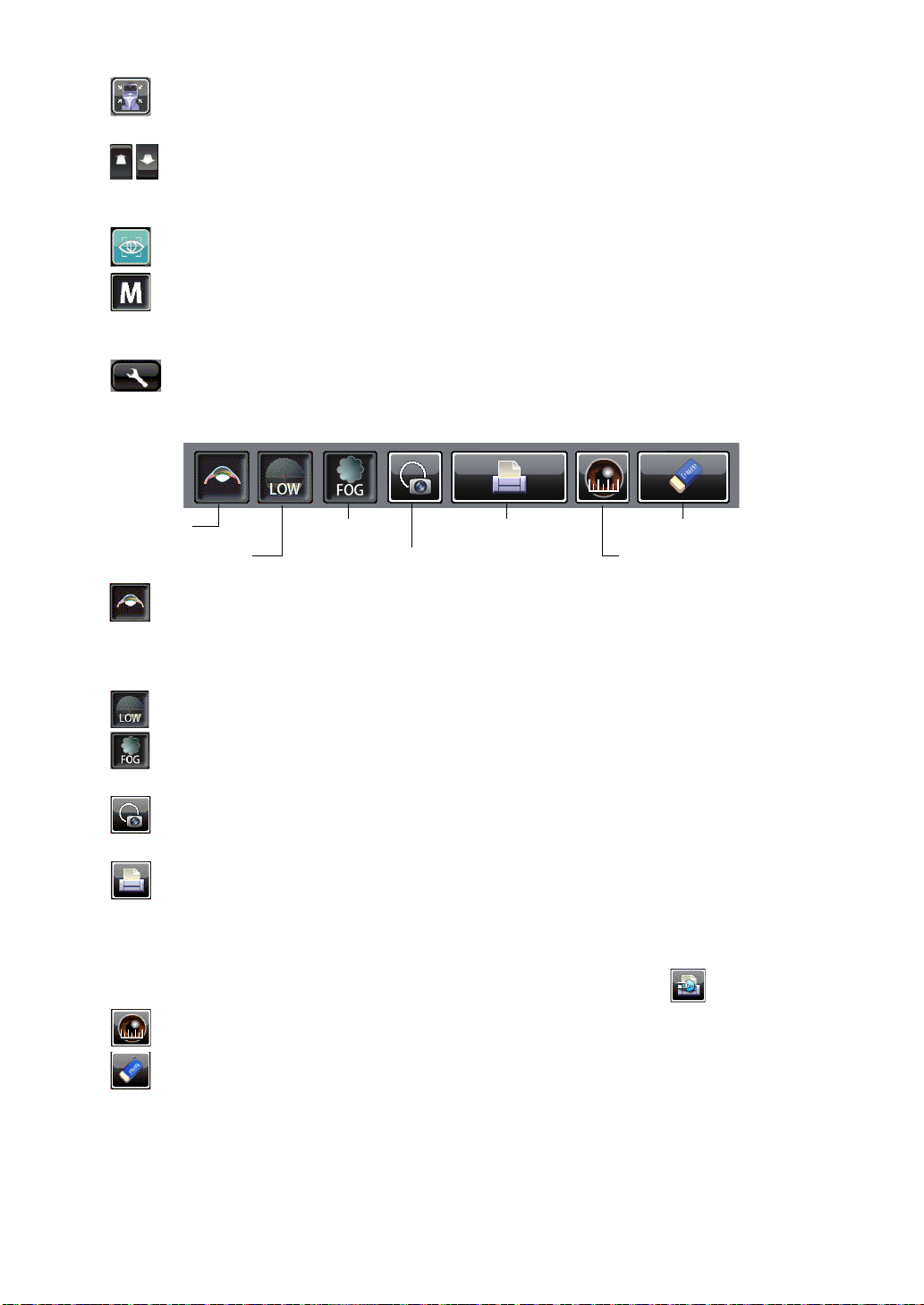
FUNCTION BUTTON
Cataract button............... If error messages occur in patient's with cataracts, push the
Cataract button may improve measurements. When the button
is selected, "CAT" is displayed on the monitor and the selected
button is framed in orange.
Fixation target button .....Brightness of the fixation target can be changed.
FOG button ....................Changes setting temporarily to perform fogging only in the first
measurement or each time in the continuous measurement.
Target image button .......The captured measurement target can be observed on the
control panel.
Print out button ..............Prints measurement results. Tap the button when no measure-
ment data is present to feed the paper.
By setting the print er mode to G raphic Print er on the Se ttings
screen, figures showing refractive conditions can be printed. In
this case, the printer button changes to .
Cornea diameter button
..Changes to cornea diameter measurement mode.
ALL CLEAR button.........Clears all measurement data.
13
COMPONENTS
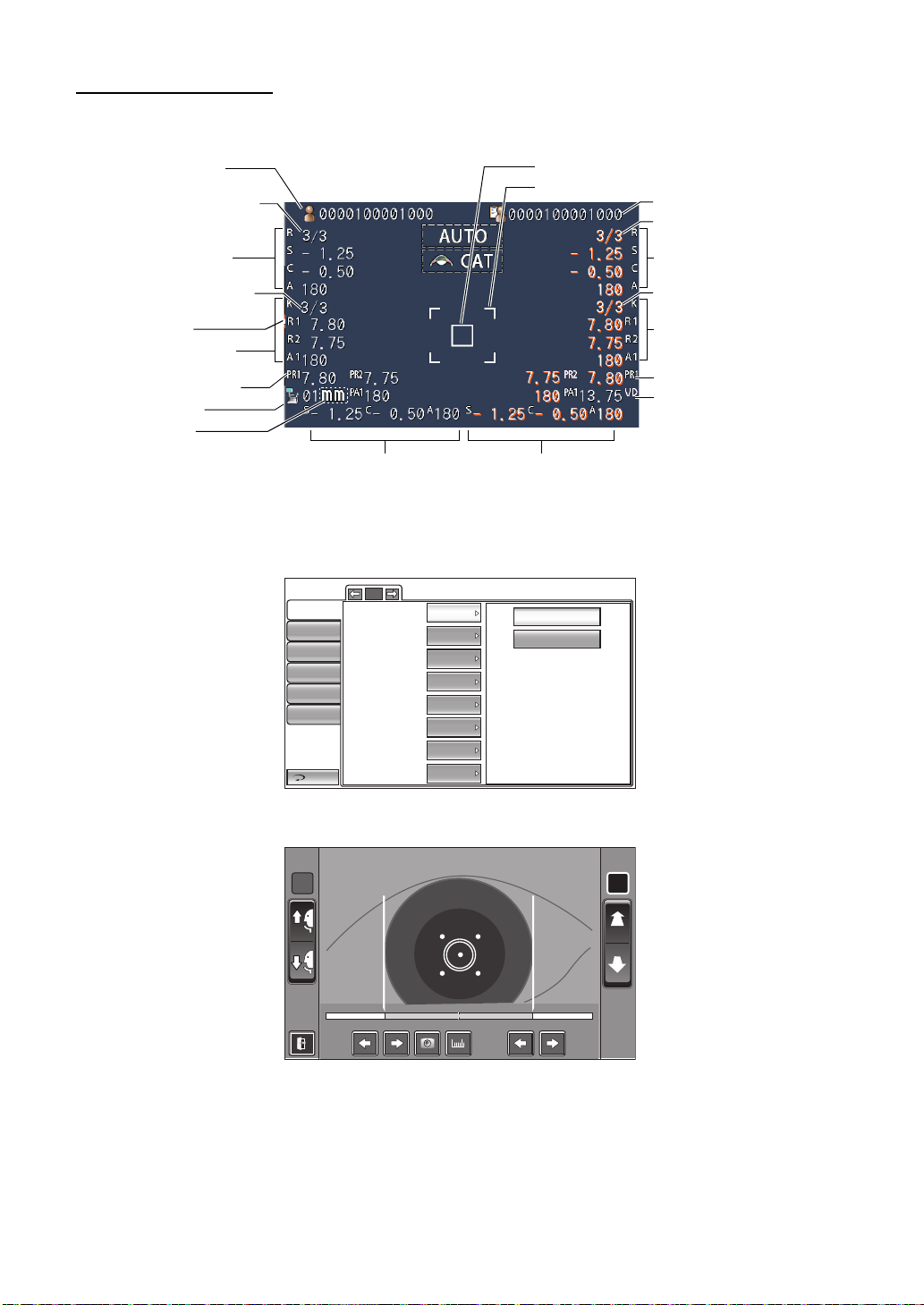
MONITOR SCREEN
Operator ID
Refractive power
measurement result (L)
Corneal curvature radius
measurement result (L)
Number of reading/setting
(L, REF)
Number of reading/setting
(L, KRT)
VD (Vertex distance)
Typical value of L measurementTypical value of R measurement
Patient No. (Patient ID
when patient ID is input)
Outer alignment mark
Alignment mark
Refractive power
measurement result (R)
Corneal curvature radius
measurement result (R)
Number of reading/setting
(R, REF)
Number of reading/setting
(R, KRT)
Device ID number
D/mm unit display
Peripheral KRT value (L)
Peripheral KRT value (R)
*Eye Height mark: Shows the position of the eye height mark on the chinrest.
*Eye Height mark
R L
R:0.00R: 0.0 0 L:9.50L :9. 50
MEASUREMENT SCREEN
SETTINGS SCREEN
Initial
Print
Comm
Operator ID
Special
CORNEA DIAMETER MEASUREMENT SCREEN
14
COMPONENTS
LAN
Return
1/5
Buzzer
Start mode
Auto Print
Printer
Patient No. reset
Show patient ID
Required patient ID
Device ID number
ON
AUTO
ON
ON
OFF
ON
OFF
1
OFF
ON
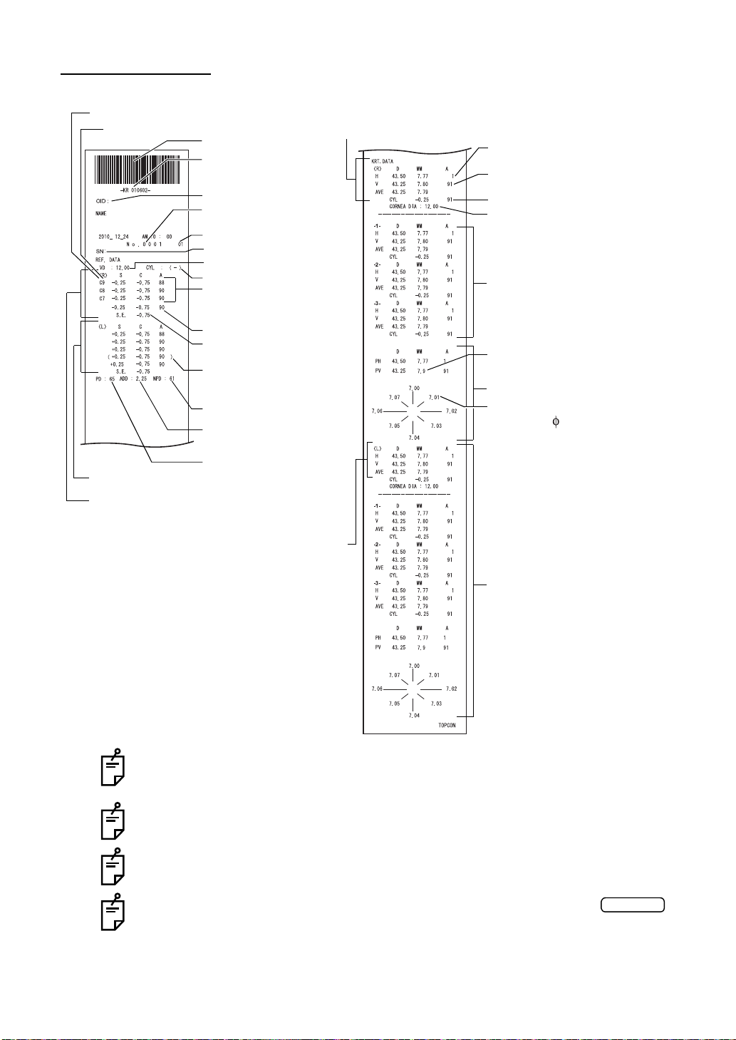
PRINTER OUTPUT
Operator ID
Device ID number
3 readings of REF right
measurement (recordable
up to 10 measurements)
Pupil distance (PD value)
VD (vertex distance)
Work ID No.
Bar code
Patient No.(Patient ID
when patient ID is input)
Serial number
Cylinder sign
Typical value of right eye
SPHERICAL EQUIVA LENT
of right eye
The ( ) mark is added when
measurement values are not
fully reliable.
ADD
(standard additional power)
Near vision PD value
Refractive power measurement result (L)
Refractive power measurement result (R)
Typical measured value of right eye corneal curvature
Typical measured value of
Left eye corneal curvature
Measured value of horizontal
corneal curvature
Measured value of vertical corneal
curvature
3 readings of kerato-cylinder value,
average value and kerato-cylinder
value (recordable up to 10 measurements each for right/left eye)
Left eye
corneal curvature measurement
Measured value of right eye cornea
Corneal astigmatic axis angle
Peripheral KRT measurement
values near 6mm
Peripheral KRT value
Typical measured value of
Peripheral KRT value (R)
C(Cataract mode) mark
Reliability factor
Cataract
KRT typical value style and KRT print format are HV
The reliability factor is defined with integers 1 to 9 in increasing order of reliability.
Additionally, if the reliability is high enough, the reliability factor is not shown on the
printout.
The Near PD value is calculated based on the ADD.
( ) appears when normal measurement is not expected du e to eyelid, eyela sh, or
blinking.
*-mark appears w hen normal measurement is not expected with the
button selected.
15
COMPONENTS
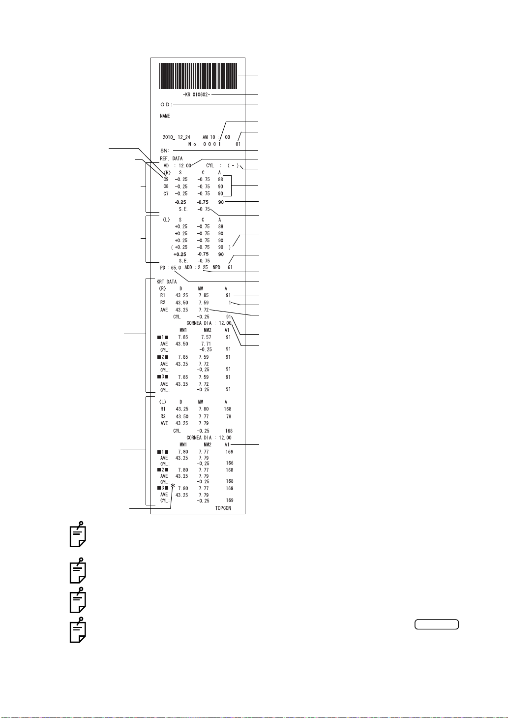
KRT typical value style and KRT print format are R1R2
Patient No. (Patient ID when patient ID is input)
Work ID No.
Cylinder sign
3 readings of REF right measurement
(recordable up to 10 measurements)
Typical value of right eye
Spherical equivalent of right eye
Pupil distance (PD value)
(mm)
Corneal astigmatic axial angle
VD (vertex distance)
Barcode
MM1: Corneal refractive power at flat meridian
MM2: Corneal refractive power at steep meridian
A1: Angle of steep meridian
Measured value of horizontal corneal curvature
Measured value of vertical corneal curvature
Operator ID
Device ID number
Serial number
The ( ) mark is added when measurement values are
not fully reliable.
ADD (ordinary additional power)
Near vision PD value
D: Average value of corneal refractive power
MM: Average value of cornea curvature radius
Measured value of right eye cornea diameter (mm)
Result of refractory power
measurement (Right eye)
Result of refractory power
measurement (Left eye)
KRT data (Right eye)
KRT data (Left eye)
C(Cataract mode) mark
Reliability factor
*-mark appears when
reliability of the measurement is too low.
Cataract
16
COMPONENTS
The reliability factor is defined with integers 1 to 9 in increasing order of reliability.
Additionally, if the reliability is high enough, the reliability factor is not shown on the
printout.
The Near PD value is calculated based on the ADD.
( ) appears when normal measurement is not expected du e to eyelid, eyela sh, or
blinking.
*-mark appears w hen normal measurement is not expected with the
button selected.

PRINTOUT FORMAT SETTING
Printout format can be cha nged by pushing "Print" in the S ettings screen. For Print se ttings,
see "SETTING FUNCTIONS ON SETUP SCREEN" on page 44.
PRESET
All: Initial setting (all measurement values are printed.)
Ave: Only typical value are printed.
Classic: Equivalent with RM/KR-8900 Classic 2
Common
REF/KRT
REF
KRT
ITEM INITIAL
Barcode OFF OFF OFF OFF
Operator ID OFF OFF OFF OFF
Name ON ON ON ON
Date ON ON ON ON
Date style YMD YMD YMD YMD
Patient ID ON ON ON ON
Device ID number OFF OFF OFF OFF
Serial number ON ON ON ON
Include error data OFF OFF OFF OFF
TOPCON logo ON ON ON ON
Message OFF OFF OFF OFF
Message data NULL NULL NULL NULL
Between the lines 0 0 0 0
Auto Cut ON ON ON ON
Print order DATA DATA DATA DATA
VD ON ON ON ON
Cylinder sign ON ON ON ON
REF format ALL ALL AVE ALL
Credibility OFF OFF OFF OFF
S.E. ON ON ON ON
PD ON ON ON ON
ADD OFF OFF OFF OFF
KRT print order D/mm D/mm D/mm D/mm
KRT format ALL ALL AVE AVE
KRT style R1R2 R1R2 R1R2 HV
KRT print format R1R2 R1R2 R1R2 HV
KRT average ON ON ON ON
KRT cylinder ON ON ON ON
Cornea diameter ON ON ON ON
VD ON ON ON ON
Cylinder sign ALL ALL AVE ALL
REF format OFF OFF OFF OFF
Credibility ON ON ON ON
S.E. ON ON ON ON
PD OFF OFF OFF OFF
ADD OFF OFF OFF OFF
KRT print order D/mm D/mm D/mm D/mm
KRT format ALL ALL AVE ALL
KRT style R1R2 R1R2 R1R2 HV
KRT print format R1R2 R1R2 R1R2 HV
KRT average ON ON ON ON
KRT cylinder ON ON ON ON
Cornea diameter ON ON ON ON
All Ave Classic
PRESET
17
COMPONENTS
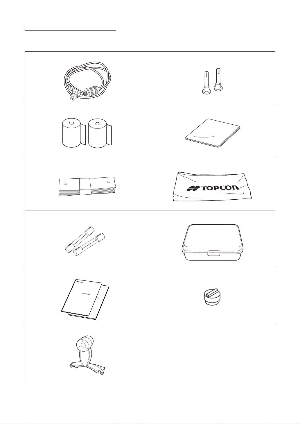
STANDARD ACCESSORIES
The following are standard accessories. Make sure that all these items are included (quantity).
Power cable (1) Chinrest tissue pin (2)
Printer paper (2) Monitor cleaner (1)
Chinrest tissue (1) Dust cover (1)
Fuse (2) Accessory case (1)
User manual, Unpacking and Assembing
(1 each)
Model eye (1)
Rubber cap (1)
18
COMPONENTS
PREPARATIONS
Holding positions Holding the instrument
External I/O terminal cover
INSTALLATION
CAUTION
CAUTION
CAUTION
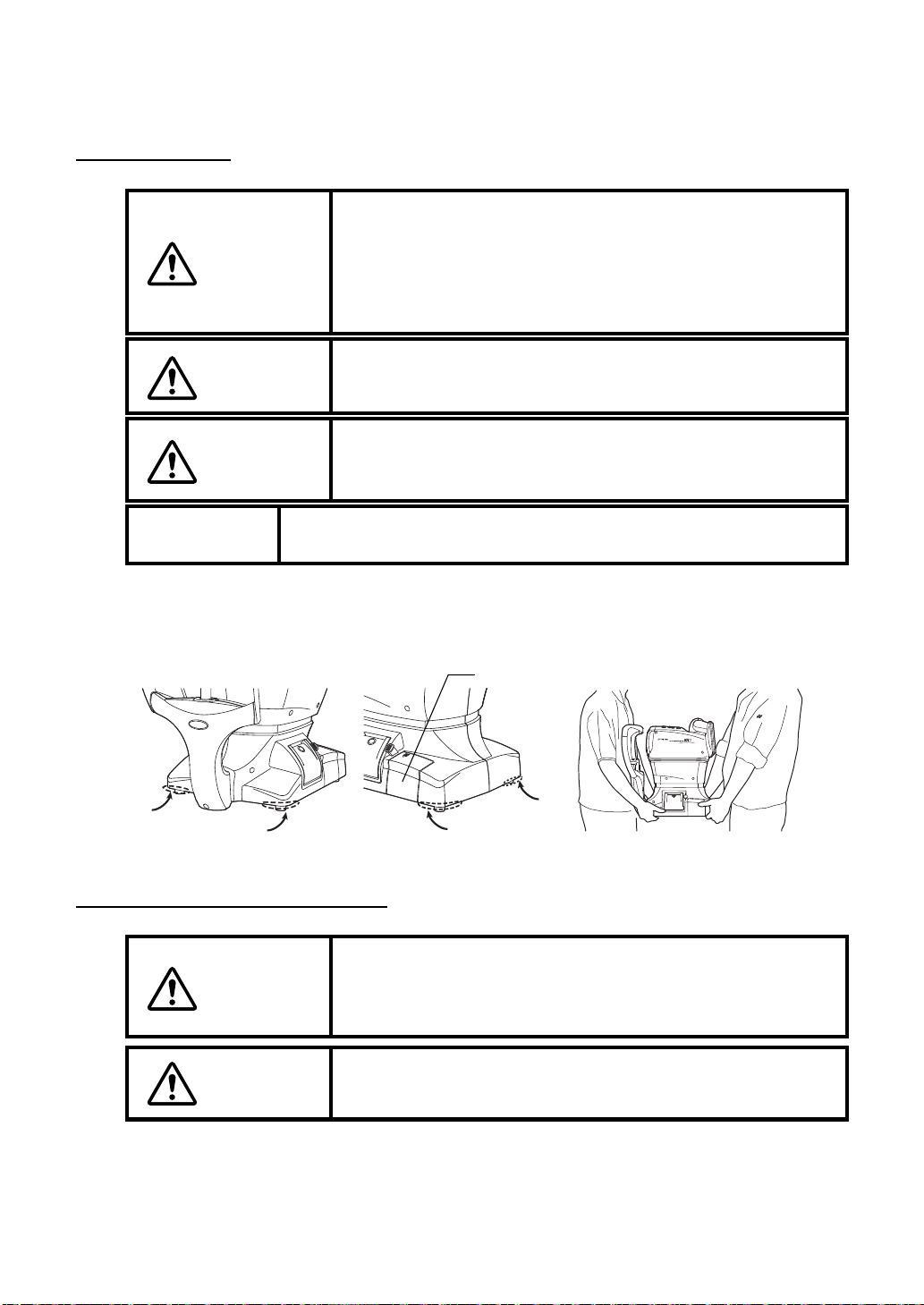
When moving the instrumen t, two people should lift from the
bottom of the device.
One person lifting the device may ca use harm to his back or
injury by falling parts. Also, holding areas other than the bottom
and holding the Exte rnal I/O terminal cove r may cause injury,
as well as damage to the instrument.
To prevent dama ge and injuries, do not install the in strument
on an uneven, unsteady or sloped surface.
When setting an instrument on an instrument table, pay attention not to injury the patient's fi ngers between the instrument
and the table.
NOTE:
The instrument should also be placed away from strong light like
direct sunlight. Auto alignment may not function properly.
1 Firmly hold the instrument at the position shown below and place it on the automatic
instrument table.
For the adjustable instrument table, see “OPTIONAL ACCESSORIES” on page 64.
CONNECTING POWER CABLE
Be sure to connec t the power plug to an AC 3-pin receptacle
WARNING
equipped with groundin g. Connection with receptacle without
grounding may cause fire and electric shock in case of s hortcircuiting.
CAUTION
To avoid electric shocks, do not handle the power plug with wet
fingers.
1 Make sure the POWER switch of the instrument is OFF.
19
PREPARATIONS
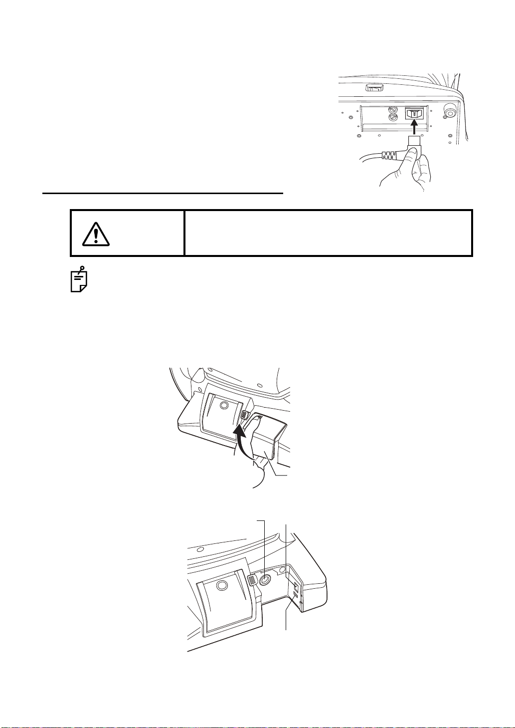
2 Tilt the body slowly so that the POWE R switch is on top and the power in let at the bo ttom
External I/O terminal cover
USB input terminal
LAN output terminalRS232C output terminal
can be seen.
3 Connect the power cable to the Power inlet.
4 Insert the power cable plug into the 3-pin AC grounding
receptacle.
CONNECTING EXTERNAL I/O TERMINALS
CAUTION
Use the external device complying with IEC60950/IEC60950-1.
DATA OUTPUT
This product can be connected to a pers onal computer (PC) and other external dev ices via
the RS232C or LAN.
To avoid electri c shock, do not touch the external connec tion
terminal and the patient at the same time.
1 Remove the External I/O terminal cover by pulling up as follows.
2 Connect the connection cable to the output terminal of the instrument.
20
PREPARATIONS
3 Connect the other end of the connection cable to the PC, etc.
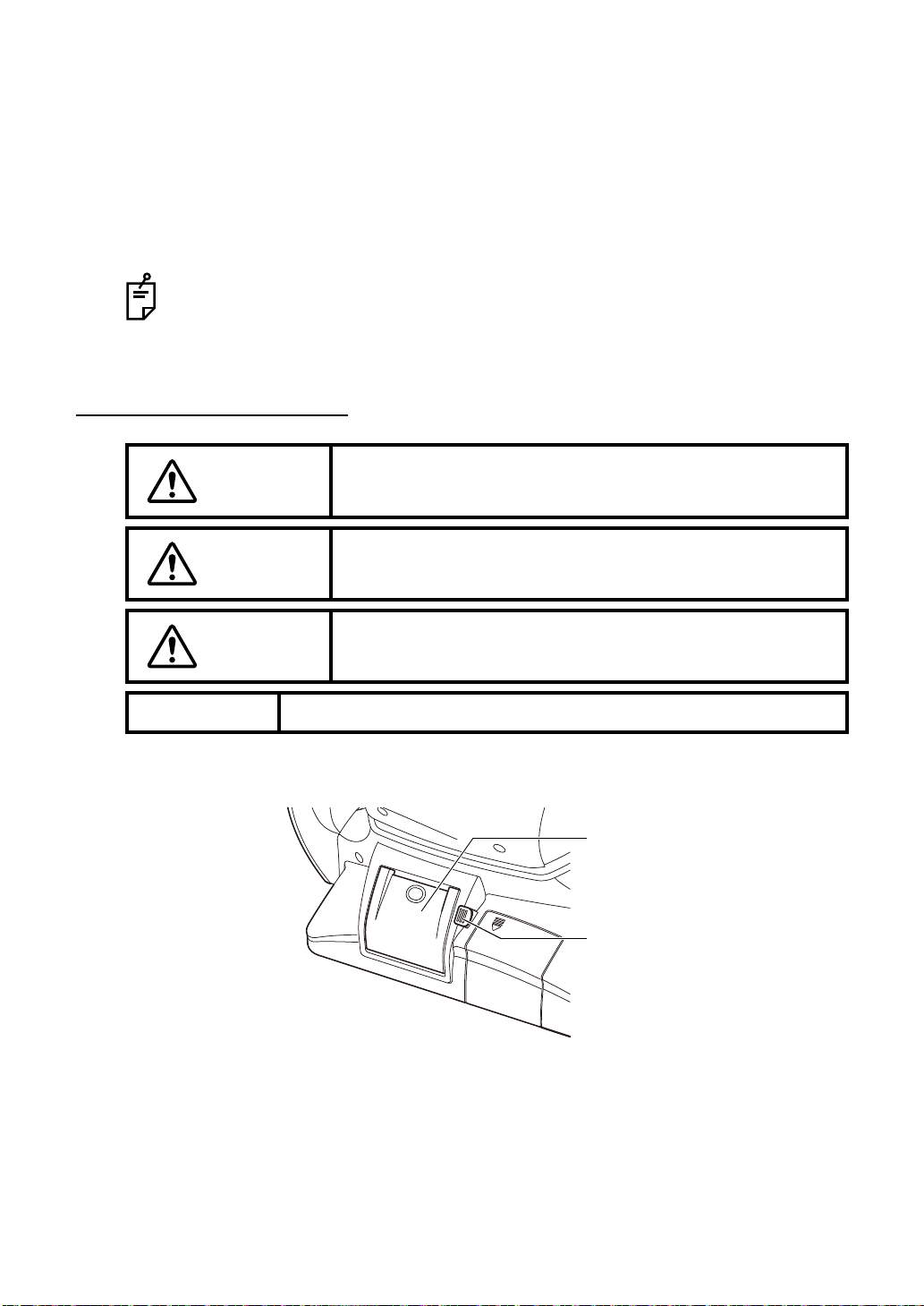
Printer cover
Printer cover open switch
4 Replace the External I/O terminal cover.
DATA INPUT
This product can be connected to a bar-code reader and other external devices via USB.
1 Connect the connection cable to the input terminal of the instrument.
2 Connect the other end of the connection cable to the external device.
For questions about connections, contact your TOPCON dealer.
PRINTER PAPER SETTING
CAUTION
CAUTION
CAUTION
NOTE:
To avoid failure or potential injury , do not open the printer cover
while the printer is in operation.
To avoid potential injury in case of malfunction, including a
paper jam, be sure to shut off the power be fore attempting to
repair it.
To avoid potential injury, do not touch the printer body including
metal parts or the paper cutter, while the printer i s in opera tion
or when replacing the printer paper.
• If you insert the printer paper backwards, printing will not start.
1 Press the printer cover open switch to open the printer cover.
21
PREPARATIONS
Loading...