


 Loading...
INSTRUCTION MANUAL
PULSE TOTAL STATION
GPT-2000 SERIES
GPT-2003
GPT-2005
GPT-2006
GPT-2009
FOREWORD
Thank you for purchasing the TOPCON Pulse Total Station, GPT-2000 series. For the best performance of the instruments, please carefully read these instructions and keep them in a convenient location for future reference.
1

General Handling Precautions
Before starting work or operation, be sure to check that the instrument is functioning correctly with normal performance.
Do not submerge the instrument into water.
The instrument can not be submerged underwater.
The instrument is designed based on the International Standard IP66, therefore it is protected from the normal rainfall.
Setting the instrument on a tripod
When mounting the instrument on a tripod, use a wooden tripod when possible. The vibrations that may occur when using a metallic tripod can effect the measuring precision.
Installing the tribrach
If the tribrach is installed incorrectly , the measuring precision could be effected. Occasionally check the adjusting screws on the tribrach. Make sure the base fixing lever is locked and the base fixing screws are tightened.
Guarding the instrument against shocks
When transporting the instrument, provide some protection to minimize risk of shocks. Heavy shocks may cause the measurement to be faulty.
Carrying the instrument
Always carry the instrument by its handgrip.
Exposing the instrument to extreme heat.
Do not leave the instrument in extreme heat for longer than necessary. It could adversely affect its performance.
Sudden changes of temperature
Any sudden change of temperature to the instrument or prism may result in a reduction of measuring distance range, i.e when taking the instrument out from a heated vehicle. Let instrument acclimate itself to ambient temperature.
Battery level check
Confirm battery level remaining before operating.
Taking the battery out
It is recommended not to take the battery out during the power is on. All the data stored is possible gone at that time. So please do your assembling or taking the battery out after the power is off.
Noise from the inside of instrument
When EDM turns on, the sound of motors from inside the instrument body may be heard. This is normal and does not effect operation of the instrument.
2

Display for Safe Use
In order to encourage the safe use of products and prevent any danger to the operator and others or damage to properties, important warnings are put on the products and inserted in the instruction manuals.
We suggest that everyone understand the meaning of the following displays and icons before reading the “Safety Cautions” and text.
|
|
Display |
Meaning |
|
|
|
|
|
|
WARNING |
Ignoring or disregard of this display may lead to the danger of death or |
|
|
||
|
|
serious injury. |
|
|
|
|
|
|
|
|
|
|
|
|
|
|
|
CAUTION |
Ignoring or disregard of this display may lead to personal injury or phys- |
|
|
||
|
|
ical damage. |
|
|
|
|
|
|
|
|
|
|
|
|
|
•Injury refers to hurt, burn, electric shock, etc.
•Physical damage refers to extensive damage to buildings or equipment and furniture.
Safety Cautions
 WARNING
•There is a risk of fire, electric shock or physical harm if you attempt to disassemble or repair the instrument yourself.
This is only to be carried out by TOPCON or an authorized dealer, only!
•Cause eye injury or blindness.
Do not look at the sun through a telescope.
•Laser beams can be dangerous, and can cause eye injury's if used incorrectly.
Never attempt to repair the instrument yourself. (Only for Laser plummet type)
•Cause eye injury or blindness.
Do not stare into beam. (Only for Laser plummet type)
•High temperature may cause fire.
Do not cover the charger while it is charging.
•Risk of fire or electric shock.
Do not use damaged power cable, plug and socket.
•Risk of fire or electric shock.
Do not use a wet battery or charger.
•May ignite explosively.
Never use an instrument near flammable gas, liquid matter, and do not use in a coal mine.
•Battery can cause explosion or injury.
Do not dispose in fire or heat.
•Risk of fire or electric shock.
Do not use any power voltage except the one given on manufacturers instructions.
•Battery can cause outbreak of fire.
Do not use any other type of charger other than the one specified.
•Risk of fire.
Do not use any other power cable other than the one specified.
•The short circuit of a battery can cause a fire.
Do not short circuit battery when storing it.
3

 CAUTION
•Use of controls or adjustment or performance of procedures other than those specified herein may result in hazardous radiation exposure.
•Do not connect or disconnect equipment with wet hands, you are at risk of electric shocks if you do!
•Risk of injury by overturn the carrying case. Do not stand or sit on the carrying cases.
•Please note that the tips of tripod can be hazardous, be aware of this when setting up or carrying the tripod.
•Risk of injury by falling down the instrument or case.
Do not use a carrying case with a damaged which belts, grips or latches .
•Do not allow skin or clothing to come into contact with acid from the batteries, if this does occur then wash off with copious amounts of water and seek medical advice.
•A plumb bob can cause an injury to a person if used incorrectly.
•It could be dangerous if the instrument falls over, please ensure you attach a handle battery to the instrument securely.
•Ensure that you mount the Tribrach correctly, failing to do so may result in injury if the tribrach were to fall over.
•It could be dangerous if the instrument falls over, please check that you fix the instrument to the tripod correctly.
•Risk of injury by falling down a tripod and an instrument. Always check that the screws of tripod are tightened.
User
1)This product is for professional use only!
The user is required to be a qualified surveyor or have a good knowledge of surveying, in order to understand the user and safety instructions, before operating, inspecting or adjusting.
2)Wear the required protectors (safety shoes, helmet, etc.) when operating.
Exceptions from Responsibility
1)The user of this product is expected to follow all operating instructions and make periodic checks of the product’s performance.
2)The manufacturer, or its representatives, assumes no responsibility for results of a faulty or intentional usage or misuse including any direct, indirect, consequential damage, and loss of profits.
3)The manufacturer, or its representatives, assumes no responsibility for consequential damage, and loss of profits by any disaster, (an earthquake, storms, floods etc.).
A fire, accident, or an act of a third party and/or a usage any other usual conditions.
4)The manufacturer, or its representatives, assumes no responsibility for any damage, and loss of profits due to a change of data, loss of data, an interruption of business etc., caused by using the product or an unusable product.
5)The manufacturer, or its representatives, assumes no responsibility for any damage, and loss of profits caused by usage except for explained in the user manual.
6)The manufacturer, or its representatives, assumes no responsibility for damage caused by wrong movement, or action due to connecting with other products.
4
Safety Standard for Laser Beam
GPT-2000 series uses the invisible laser beam. The GPT-2000 series are manufactured and sold in accordance with "Performance Standards for Light-Emitting Products" (FDA/BRH 21 CFR 1040) or "Radiation Safety of Laser Products, Equipment Classification, Requirements and User`s Guide" (IEC Publication 825) provided on the safety standard for laser beam.
As per the said standard, the GPT-2000 series plumb laser type is classified as "Class 1 (l) Laser Products".
In case of any failure, do not disassemble the instrument. Contact TOPCON or your TOPCON dealer.
Safety Standard for Laser Beam
(Only for GPT-2000 series Plumb Laser Type)
GPT-2000 series plumb laser type uses the visible laser beam. The GPT-2000 series plumb laser type are manufactured and sold in accordance with "Performance Standards for Light-Emitting Products" (FDA/BRH 21 CFR 1040) or "Radiation Safety of Laser Products, Equipment Classification, Requirements and User`s Guide" (IEC Publication 825) provided on the safety standard for laser beam. As per the said standard, the GPT-2000 series plumb laser type is classified as "Class 2 (II) Laser Products".
In case of any failure, do not disassemble the instrument. Contact TOPCON or your TOPCON dealer.
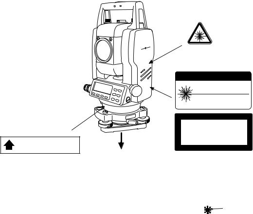
Labels
Find the labels which describes the caution and safety about the laser beam as follows in GPT-2000 series.
We request you to replace it one anytime the caution labels are damaged or lost and paste a new one at the same place. You can get the labels from Topcon or your dealer.
GPT-2000 series
Laser Plummet type
|
Warning Label |
|
Explanatory Label |
|
C A U T I O N |
|
LASER RADIATION-DO NOT |
|
STARE INTO BEAM |
|
WAVE LENGTH 633nm |
|
1mW MAXIMUM OUTPUT |
|
CLASS IILASER PRODUCT |
Aperture Label |
LASER RADIATION |
|
DO NOT STARE INTO BEAM |
AVOID EXPOSURE |
Maximum output 1 W Wave length 633nm |
CLASS 2 LASER PRODUCT |
|
LASER LIGHT IS EMITTED |
|
FROM THIS APERTURE |
Beam aperture |
|
Depending on the country where the instrument is sold, either of these labels may be found on the GPT-2000 series laser plummet type.
Symbol mark while the laser is emitting.
The following symbol mark will appear at the right side of the second line.
TILT |
SENSOR:[XY-ON] |
|
X:-0°00'25" |
Symbol mark |
|
Y: 0°00'20" |
|
|
X-ON |
XY-ON OFF L.PL |
|
|
|
|
5
Contents
FOREWORD . . . . . . . . . . . . . . . . . . . . . . . . . . . . . . . . . . . . . . . . . . . . . . . . . . 1
General Handling Precautions. . . . . . . . . . . . . . . . . . . . . . . . . . . . . . . . . . . . . . . . . . . . . . . .2
Display for Safe Use . . . . . . . . . . . . . . . . . . . . . . . . . . . . . . . . . . . . . . . . . . . . . . . . . . . . . . .3 Safety Cautions . . . . . . . . . . . . . . . . . . . . . . . . . . . . . . . . . . . . . . . . . . . . . . . . . . . . . . . . 3
User . . . . . . . . . . . . . . . . . . . . . . . . . . . . . . . . . . . . . . . . . . . . . . . . . . . . . . . . . . . . . . . . . . . . .4 Exceptions from Responsibility . . . . . . . . . . . . . . . . . . . . . . . . . . . . . . . . . . . . . . . . . . . . . . . .4 Safety Standard for Laser Beam . . . . . . . . . . . . . . . . . . . . . . . . . . . . . . . . . . . . . . . . . . . . . . .5 Safety Standard for Laser Beam . . . . . . . . . . . . . . . . . . . . . . . . . . . . . . . . . . . . . . . . . . . . . . .5 Labels . . . . . . . . . . . . . . . . . . . . . . . . . . . . . . . . . . . . . . . . . . . . . . . . . . . . . . . . . . . . . . . . . . .5 Symbol mark while the laser is emitting. . . . . . . . . . . . . . . . . . . . . . . . . . . . . . . . . . . . . . . . . .5 Standard Set Composition. . . . . . . . . . . . . . . . . . . . . . . . . . . . . . . . . . . . . . . . . . . . . . . . . . . .9
1 NOMENCLATURE AND FUNCTIONS . . . . . . . . . . . . . . . . . . . . . . . . . . 1-1
1.1 Nomenclature . . . . . . . . . . . . . . . . . . . . . . . . . . . . . . . . . . . . . . . . . . . . . . . . . . . . . . . . 1-1 1.2 Display . . . . . . . . . . . . . . . . . . . . . . . . . . . . . . . . . . . . . . . . . . . . . . . . . . . . . . . . . . . . . 1-3 1.3 Operating Key. . . . . . . . . . . . . . . . . . . . . . . . . . . . . . . . . . . . . . . . . . . . . . . . . . . . . . . . 1-4 1.4 Function Key (Soft Key) . . . . . . . . . . . . . . . . . . . . . . . . . . . . . . . . . . . . . . . . . . . . . . . . 1-4 1.5 Serial signal RS-232C connector . . . . . . . . . . . . . . . . . . . . . . . . . . . . . . . . . . . . . . . . . 1-6
2 PREPARATION FOR MEASUREMENT . . . . . . . . . . . . . . . . . . . . . . . . . 2-1
2.1 Power Connection . . . . . . . . . . . . . . . . . . . . . . . . . . . . . . . . . . . . . . . . . . . . . . . . . . . . 2-1 2.2 Setting Instrument Up For Measurement . . . . . . . . . . . . . . . . . . . . . . . . . . . . . . . . . . . 2-2 2.3 Power Switch Key ON . . . . . . . . . . . . . . . . . . . . . . . . . . . . . . . . . . . . . . . . . . . . . . . . . 2-3 2.4 Battery Power Remaining Display . . . . . . . . . . . . . . . . . . . . . . . . . . . . . . . . . . . . . . . . 2-4 2.5 Vertical and Horizontal Angle Tilt Correction . . . . . . . . . . . . . . . . . . . . . . . . . . . . . . . . 2-5 2.6 How to Enter Alphanumeric characters . . . . . . . . . . . . . . . . . . . . . . . . . . . . . . . . . . . . 2-7 2.7 Point Guide (Only for Point Guide type) . . . . . . . . . . . . . . . . . . . . . . . . . . . . . . . . . . . . 2-8 2.8 Laser Plummet ON/OFF (Only for Laser Plummet type) . . . . . . . . . . . . . . . . . . . . . . . 2-9
3 ANGLE MEASUREMENT . . . . . . . . . . . . . . . . . . . . . . . . . . . . . . . . . . . . 3-1
3.1 Measuring Horizontal Angle Right and Vertical Angle . . . . . . . . . . . . . . . . . . . . . . . . . 3-1 3.2 Switching Horizontal Angle Right/Left. . . . . . . . . . . . . . . . . . . . . . . . . . . . . . . . . . . . . . 3-2 3.3 Measuring from the Required Horizontal Angle . . . . . . . . . . . . . . . . . . . . . . . . . . . . . . 3-2 3.3.1 Setting by Holding the Angle . . . . . . . . . . . . . . . . . . . . . . . . . . . . . . . . . . . . . . . . 3-2 3.3.2 Setting a Horizontal Angle from the Keys . . . . . . . . . . . . . . . . . . . . . . . . . . . . . . 3-3 3.4 Vertical Angle Percent Grade(%) Mode . . . . . . . . . . . . . . . . . . . . . . . . . . . . . . . . . . . . 3-3 3.5 Repetition Angle Measurement . . . . . . . . . . . . . . . . . . . . . . . . . . . . . . . . . . . . . . . . . . 3-4 3.6 Buzzer Sounding for Horizontal Angle 90° Increments . . . . . . . . . . . . . . . . . . . . . . . . 3-5 3.7 Compasses ( vertical angle) . . . . . . . . . . . . . . . . . . . . . . . . . . . . . . . . . . . . . . . . . . . . . 3-6
4 DISTANCE MEASUREMENT . . . . . . . . . . . . . . . . . . . . . . . 4-1
4.1 Setting of the Atmospheric Correction . . . . . . . . . . . . . . . . . . . . . . . . . . . . . . . . . . . . . 4-1 4.2 Setting of the Correction for Prism Constant / Non-prism Constant . . . . . . . . . . . . . . . 4-1 4.3 Distance Measurement (Continuous Measurement) . . . . . . . . . . . . . . . . . . . . . . . . . . 4-2 4.4 Distance Measurement (N-time Measurement/Single Measurement) . . . . . . . . . . . . . . . . . . . 4-3 4.5 Fine Mode/Tracking Mode/Coarse Mode . . . . . . . . . . . . . . . . . . . . . . . . . . . . . . . . . . . 4-4 4.6 Stake Out (S.O) . . . . . . . . . . . . . . . . . . . . . . . . . . . . . . . . . . . . . . . . . . . . . . . . . . . . . . 4-5 4.7 Offset Measurement . . . . . . . . . . . . . . . . . . . . . . . . . . . . . . . . . . . . . . . . . . . . . . . . . . . 4-6
4.7.1 Angle Offset . . . . . . . . . . . . . . . . . . . . . . . . . . . . . . . . . . . . . . . . . . . . . . . . . . . . . 4-7 4.7.2 Distance Offset Measurement . . . . . . . . . . . . . . . . . . . . . . . . . . . . . . . . . . . . . . . 4-9 4.7.3 Plane Offset Measurement . . . . . . . . . . . . . . . . . . . . . . . . . . . . . . . . . . . . . . . . 4-11 4.7.4 Column Offset Measurement . . . . . . . . . . . . . . . . . . . . . . . . . . . . . . . . . . . . . . . 4-13
5 COORDINATE MEASUREMENT . . . . . . . . . . . . . . . . . . . . . . . . . . . . . . 5-1
5.1 Setting Coordinate Values of Occupied Point. . . . . . . . . . . . . . . . . . . . . . . . . . . . . . . . 5-1 5.2 Setting Height of the Instrument . . . . . . . . . . . . . . . . . . . . . . . . . . . . . . . . . . . . . . . . . . 5-2 5.3 Setting Height of Target (Prism Height) . . . . . . . . . . . . . . . . . . . . . . . . . . . . . . . . . . . . 5-2 5.4 Execution of Coordinate Measuring . . . . . . . . . . . . . . . . . . . . . . . . . . . . . . . . . . . . . . . 5-3
6 SPECIAL MODE (Menu Mode). . . . . . . . . . . . . . . . . . . . . . . . . . . . . . . . 6-1
6
6.1 Application Measurement (PROGRAMS) . . . . . . . . . . . . . . . . . . . . . . . . . . . . . . . . . . 6-2 6.1.1 Remote Elevation measurement (REM) . . . . . . . . . . . . . . . . . . . . . . . . . . . . . . . 6-2 6.1.2 Missing Line Measurement (MLM). . . . . . . . . . . . . . . . . . . . . . . . . . . . . . . . . . . . 6-5 6.1.3 Setting Z Coordinate of Occupied Point. . . . . . . . . . . . . . . . . . . . . . . . . . . . . . . . 6-8 6.1.4 Area Calculation. . . . . . . . . . . . . . . . . . . . . . . . . . . . . . . . . . . . . . . . . . . . . . . . . 6-11 6.1.5 Point to Line Measurement . . . . . . . . . . . . . . . . . . . . . . . . . . . . . . . . . . . . . . . . 6-14
6.2 Setting the GRID FACTOR. . . . . . . . . . . . . . . . . . . . . . . . . . . . . . . . . . . . . . . . . . . . . 6-16 6.3 Setting Illumination of Display and Cross Hairs. . . . . . . . . . . . . . . . . . . . . . . . . . . . . 6-17 6.4 Setting Mode 1 . . . . . . . . . . . . . . . . . . . . . . . . . . . . . . . . . . . . . . . . . . . . . . . . . . . . . . 6-18 6.4.1 Setting Minimum Reading . . . . . . . . . . . . . . . . . . . . . . . . . . . . . . . . . . . . . . . . . 6-18 6.4.2 Auto Power Off. . . . . . . . . . . . . . . . . . . . . . . . . . . . . . . . . . . . . . . . . . . . . . . . . . 6-19 6.4.3 Vertical and Horizontal Angle Tilt correction ( Tilt ON/OFF) . . . . . . . . . . . . . . . 6-20 6.4.4 Systematic Error of Instrument Correction (only for GPT-2003/2005/2006) . . . 6-20 6.4.5 Selecting Battery Type. . . . . . . . . . . . . . . . . . . . . . . . . . . . . . . . . . . . . . . . . . . . 6-21 6.5 Setting Contrast of Display . . . . . . . . . . . . . . . . . . . . . . . . . . . . . . . . . . . . . . . . . . . . 6-21
7 DATA COLLECTION. . . . . . . . . . . . . . . . . . . . . . . . . . . . . . . . . . . . . . . . 7-1
7.1 Preparation . . . . . . . . . . . . . . . . . . . . . . . . . . . . . . . . . . . . . . . . . . . . . . . . . . . . . . . . . . 7-3 7.1.1 Selecting a File for Data Collection . . . . . . . . . . . . . . . . . . . . . . . . . . . . . . . . . . . 7-3 7.1.2 Selecting a Coordinate File for Data Collection . . . . . . . . . . . . . . . . . . . . . . . . . . 7-4 7.1.3 Occupied Point and Backsight Point . . . . . . . . . . . . . . . . . . . . . . . . . . . . . . . . . . 7-4 7.2 Operational Procedure of “DATA COLLECT” . . . . . . . . . . . . . . . . . . . . . . . . . . . . . . . . 7-7 7.2.1 Searching the recorded data . . . . . . . . . . . . . . . . . . . . . . . . . . . . . . . . . . . . . . . . 7-8 7.2.2 Entering PCODE / ID using PCODE Library . . . . . . . . . . . . . . . . . . . . . . . . . . . . 7-8 7.2.3 Entering PCODE / ID from the list of PCODE . . . . . . . . . . . . . . . . . . . . . . . . . . . 7-9 7.3 Data Collect Offset Measurement mode. . . . . . . . . . . . . . . . . . . . . . . . . . . . . . . . . . . 7-10 7.3.1 Angle Offset Measurement . . . . . . . . . . . . . . . . . . . . . . . . . . . . . . . . . . . . . . . . 7-10 7.3.2 Distance Offset Measurement . . . . . . . . . . . . . . . . . . . . . . . . . . . . . . . . . . . . . . 7-12 7.3.3 Plane Offset Measurement . . . . . . . . . . . . . . . . . . . . . . . . . . . . . . . . . . . . . . . . 7-14 7.3.4 Column Offset Measurement . . . . . . . . . . . . . . . . . . . . . . . . . . . . . . . . . . . . . . . 7-16 7.4 NEZ Auto Calculation . . . . . . . . . . . . . . . . . . . . . . . . . . . . . . . . . . . . . . . . . . . . . . . . . 7-17 7.5 Editing PCODE Library [PCODE INPUT] . . . . . . . . . . . . . . . . . . . . . . . . . . . . . . . . . . 7-18 7.6 Setting Parameter of Data Collect [CONFIG.] . . . . . . . . . . . . . . . . . . . . . . . . . . . . . . 7-19
8 LAYOUT . . . . . . . . . . . . . . . . . . . . . . . . . . . . . . . . . . . . . . . . . . . . . . . . . 8-1
8.1 Preparation . . . . . . . . . . . . . . . . . . . . . . . . . . . . . . . . . . . . . . . . . . . . . . . . . . . . . . . . . . 8-3 8.1.1 Setting the GRID FACTOR . . . . . . . . . . . . . . . . . . . . . . . . . . . . . . . . . . . . . . . . . 8-3 8.1.2 Selecting Coordinate Data File . . . . . . . . . . . . . . . . . . . . . . . . . . . . . . . . . . . . . . 8-4 8.1.3 Setting Occupied Point . . . . . . . . . . . . . . . . . . . . . . . . . . . . . . . . . . . . . . . . . . . . 8-5 8.1.4 Setting Backsight Point . . . . . . . . . . . . . . . . . . . . . . . . . . . . . . . . . . . . . . . . . . . . 8-7
8.2 Executing a Layout . . . . . . . . . . . . . . . . . . . . . . . . . . . . . . . . . . . . . . . . . . . . . . . . . . . . 8-9 8.3 Setting a New Point . . . . . . . . . . . . . . . . . . . . . . . . . . . . . . . . . . . . . . . . . . . . . . . . . . 8-11 8.3.1 Side Shot Method . . . . . . . . . . . . . . . . . . . . . . . . . . . . . . . . . . . . . . . . . . . . . . . 8-11 8.3.2 Resection Method . . . . . . . . . . . . . . . . . . . . . . . . . . . . . . . . . . . . . . . . . . . . . . . 8-13
9 MEMORY MANAGER MODE . . . . . . . . . . . . . . . . . . . . . . . . . . . . . . . . . 9-1
9.1 Display Internal Memory Status . . . . . . . . . . . . . . . . . . . . . . . . . . . . . . . . . . . . . . . . . . 9-2 9.2 Searching Data . . . . . . . . . . . . . . . . . . . . . . . . . . . . . . . . . . . . . . . . . . . . . . . . . . . . . . . 9-3 9.2.1 Measured Data Searching . . . . . . . . . . . . . . . . . . . . . . . . . . . . . . . . . . . . . . . . . . 9-3 9.2.2 Coordinate Data Searching . . . . . . . . . . . . . . . . . . . . . . . . . . . . . . . . . . . . . . . . . 9-5 9.2.3 PCODE LIBRARY Searching. . . . . . . . . . . . . . . . . . . . . . . . . . . . . . . . . . . . . . . . 9-6 9.3 FILE MAINTENANCE . . . . . . . . . . . . . . . . . . . . . . . . . . . . . . . . . . . . . . . . . . . . . . . . . . 9-7 9.3.1 Rename a File . . . . . . . . . . . . . . . . . . . . . . . . . . . . . . . . . . . . . . . . . . . . . . . . . . . 9-8 9.3.2 Searching Data in a File. . . . . . . . . . . . . . . . . . . . . . . . . . . . . . . . . . . . . . . . . . . . 9-8 9.3.3 Deleting a File . . . . . . . . . . . . . . . . . . . . . . . . . . . . . . . . . . . . . . . . . . . . . . . . . . . 9-9 9.4 Coordinate Data Direct Key Input . . . . . . . . . . . . . . . . . . . . . . . . . . . . . . . . . . . . . . . . 9-10 9.5 Delete a Coordinate Data from a File . . . . . . . . . . . . . . . . . . . . . . . . . . . . . . . . . . . . . 9-11 9.6 Editing PCODE Library . . . . . . . . . . . . . . . . . . . . . . . . . . . . . . . . . . . . . . . . . . . . . . . . 9-12 9.7 Data Communications . . . . . . . . . . . . . . . . . . . . . . . . . . . . . . . . . . . . . . . . . . . . . . . . 9-13 9.7.1 Sending Data . . . . . . . . . . . . . . . . . . . . . . . . . . . . . . . . . . . . . . . . . . . . . . . . . . . 9-13
7
9.7.2 Loading Data . . . . . . . . . . . . . . . . . . . . . . . . . . . . . . . . . . . . . . . . . . . . . . . . . . . 9-14 9.7.3 Setting Parameter of Data Communications . . . . . . . . . . . . . . . . . . . . . . . . . . . 9-15 9.8 Initialization . . . . . . . . . . . . . . . . . . . . . . . . . . . . . . . . . . . . . . . . . . . . . . . . . . . . . . . . . 9-16
10 SET AUDIO MODE . . . . . . . . . . . . . . . . . . . . . . . . . . . . . . . . . . . . . . . 10-1 11 SETTING THE PRISM / NON-PRISM CONSTANT VALUE . . . . . . . 11-1 12 SETTING ATMOSPHERIC CORRECTION . . . . . . . . . . . . . . . . . . . . 12-1
12.1 Calculation of Atmospheric Correction . . . . . . . . . . . . . . . . . . . . . . . . . . . . . . . . . . . 12-1 12.2 Setting of Atmospheric Correction Value . . . . . . . . . . . . . . . . . . . . . . . . . . . . . . . . . 12-1
13 CORRECTION FOR REFRACTION AND EARTH CURVATURE . . . 13-1
13.1 Distance Calculation Formula. . . . . . . . . . . . . . . . . . . . . . . . . . . . . . . . . . . . . . . . . . 13-1
14 POWER SOURCE AND CHARGING . . . . . . . . . . . . . . . . . . . . . . . . . 14-1
14.1 On-board Battery BT-52QA . . . . . . . . . . . . . . . . . . . . . . . . . . . . . . . . . . . . . . . . . . . 14-1
15 DETACH/ATTACH OF TRIBRACH. . . . . . . . . . . . . . . . . . . . . . . . . . . 15-1 16 SELECTING MODE. . . . . . . . . . . . . . . . . . . . . . . . . . . . . . . . . . . . . . . 16-1
16.1 Items of the Selecting Mode . . . . . . . . . . . . . . . . . . . . . . . . . . . . . . . . . . . . . . . . . . . 16-1 16.2 How to Set Selecting Mode . . . . . . . . . . . . . . . . . . . . . . . . . . . . . . . . . . . . . . . . . . . 16-3
17 CHECK AND ADJUSTMENT . . . . . . . . . . . . . . . . . . . . . . . . . . . . . . . 17-1
17.1 |
Checking and adjusting of instrument constant . . . . . . . . . . . . . . . . . . . . . . . . . . . |
. 17-1 |
|
17.1.1 |
Checking of the accuracy of the non-prism mode . . . . . . . . . . . . . . . . . . . . . |
. 17-1 |
|
17.2 |
Checking the Optical Axis. . . . . . . . . . . . . . . . . . . . . . . . . . . . . . . . . . . . . . . . . . . . |
. 17-2 |
|
17.3 |
Checking/Adjusting the Theodolite Functions. . . . . . . . . . . . . . . . . . . . . . . . . . . . . |
. 17-4 |
|
17.3.1 |
Checking /Adjusting the Plate Level . . . . . . . . . . . . . . . . . . . . . . . . . . . . . . . |
. 17-5 |
|
17.3.2 |
Checking /Adjusting the Circular Level . . . . . . . . . . . . . . . . . . . . . . . . . . . . . |
. 17-5 |
|
17.3.3 |
Adjustment of the Vertical Cross-hair . . . . . . . . . . . . . . . . . . . . . . . . . . . . . . |
. 17-6 |
|
17.3.4 |
Collimation of the Instrument . . . . . . . . . . . . . . . . . . . . . . . . . . . . . . . . . . . . . |
. 17-7 |
|
17.3.5 |
Checking / Adjusting the Optical Plummet Telescope . . . . . . . . . . . . . . . . . . |
. 17-8 |
|
17.3.6 |
Checking / Adjusting the Laser Plummet (For Laser Plummet type) . . . . . . . |
. 17-9 |
|
17.3.7 |
Adjustment of Vertical Angle 0 Datum . . . . . . . . . . . . . . . . . . . . . . . . . . . . . . |
17-10 |
|
|
17.4 |
How to Set the Instrument Constant Value. . . . . . . . . . . . . . . . . . . . . . . . |
. . . . . . . 17-11 |
|
17.5 |
Adjustment of Compensation Systematic Error of Instrument . . . . . . . . . |
. . . . . . . 17-12 |
18 |
PRECAUTIONS . . . . . . . . . . . . . . . . . . . . . . . . . . . . . . . . . . . . . |
. . . . . 18-1 |
|
19 |
SPECIAL ACCESSORIES . . . . . . . . . . . . . . . . . . . . . . . . . . . . |
. . . . . 19-1 |
|
20 |
BATTERY SYSTEM . . . . . . . . . . . . . . . . . . . . . . . . . . . . . . . . . |
. . . . . 20-1 |
|
21 |
PRISM SYSTEM . . . . . . . . . . . . . . . . . . . . . . . . . . . . . . . . . . . . |
. . . . . 21-1 |
|
22 |
ERROR DISPLAYS . . . . . . . . . . . . . . . . . . . . . . . . . . . . . . . . . . |
. . . . . 22-1 |
|
23 |
SPECIFICATIONS . . . . . . . . . . . . . . . . . . . . . . . . . . . . . . . . . . . |
. . . . . 23-1 |
|
APPENDIX ..................................................................................... |
Appendix-1 |
||
|
Dual Axis Compensation ....................................................................................... |
Appendix-1 |
|
|
Precaution when Charging or Storing Batteries..................................................... |
Appendix-3 |
|
8
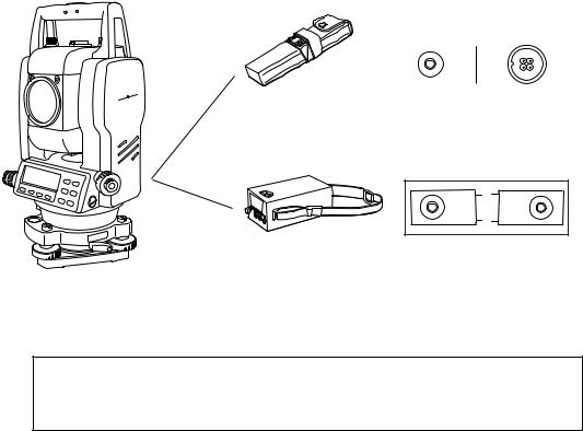
Standard Set Composition
1) GPT-2000 series (with lens cap) . . . . . . . . . . . . . . . . . . . . . . . . . . . . . . 1 each 2) On-board Battery BT-52QA . . . . . . . . . . . . . . . . . . . . . . . . . . . . . . . . . . 1 each 3) Battery charger BC-27BR or BC-27CR . . . . . . . . . . . . . . . . . . . . . . . . . 1 each
4) Tool kit with case [2 rod pins, screwdriver , hexagonal wrench
cleaning brush, silicon cloth] . . . . . . . . . . . . . . . . . . . . . . . . . . . . . . . . . 1 set 5) Plastic carrying case . . . . . . . . . . . . . . . . . . . . . . . . . . . . . . . . . . . . . . . 1 each 6) Sun shade . . . . . . . . . . . . . . . . . . . . . . . . . . . . . . . . . . . . . . . . . . . . . . . 1 each 7) Plastic rain cover . . . . . . . . . . . . . . . . . . . . . . . . . . . . . . . . . . . . . . . . . . 1 each 8) Instruction manual . . . . . . . . . . . . . . . . . . . . . . . . . . . . . . . . . . . . . . . . . 1 each
(Make sure that all of the above items are with the instrument when purchased.)
Remarks:
1)Battery charger BC-27CR is for AC 230V use and BC-27BR is for AC 120V use.
2)Plumb bob set and plumb bob hook are supplied for certain markets.
3)Additional On-board Battery BT-52QA may be included in some markets.
9
1 NOMENCLATURE AND FUNCTIONS
1NOMENCLATURE AND FUNCTIONS
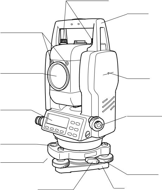
1.1Nomenclature
Handgrip locking screw
Point guide
(Point guide type only)
Objective lens
Display unit
(Only for GPT-2003/ 2005)
Circular level
Adjustment screw for circular level
Handgrip
Instrument center mark
Optical plummet telescope
(Optical plummet telescope type only)
Leveling screw
Tribrach fixing lever |
Base |
|
1-1

Sighting collimator
Telescope focusing knob
Telescope grip
Telescope eyepiece
*Vertical motion clamp
*Vertical tangent screw
Plate level
Display unit
1 NOMENCLATURE AND FUNCTIONS
Battery locking lever
On-board battery
BT-52QA
Instrument center mark
Horizontal tangent screw
Horizontal motion clamp
Power supply connector
Serial Signal connector
*The position of vertical motion clamp and Vertical tangent screw will differ depending on the market.
1-2
1 NOMENCLATURE AND FUNCTIONS
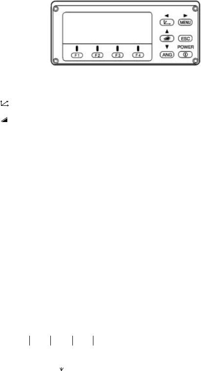
1.2Display
●Display
The display uses a dot matrix LCD which has 4 lines and 20 characters per line. In general, the upper three lines display measured data, and the bottom line displays the soft key function which changes with the measuring mode.
●Contrast and Illumination
The contrast and illumination of display window are adjusted. See Chapter 6 “SPECIAL MODE (Menu Mode)”.
●Example
V : 90°10'20" HR: 120°30'40"
0SET HOLD HSET P1↓
Angle measurement mode
V-angle : 90°10’20”
H-angle : 120°30’40”
Feet unit
HR: 120°30'40" HD* 123.45 f VD: 12.34 f
MEAS MODE NP/P P1↓
HR: 120°30'40" HD* 65.432 m VD: 12.345 m MEAS MODE NP/P P1↓
Distance measurement mode
Horizontal-angle |
: |
120°30’40” |
Horizontal distance : |
65.432m |
|
Relative elevation |
: |
12.345m |
Feet and inch unit
HR: 120°30'40"
HD* 123.04.6f
VD: 12.03.4f
MEAS MODE NP/P P1↓
Horizontal-angle |
: |
120°30’40” |
Horizontal distance |
: |
123.45ft |
Relative elevation |
: |
12.34ft |
Horizontal-angle |
: |
120°30’40” |
Horizontal distance |
: |
123ft4in6/8in |
Relative elevation |
: |
12ft3in4/8in |
● Display marks
Display |
Contents |
Display |
Content |
V |
V-angle |
|
EDM working |
|
|
|
|
HR |
H-angle right |
m |
Meter unit |
|
|
|
|
HL |
H-angle left |
f |
Feet unit / Feet and inch unit |
|
|
|
|
HD |
Horizontal distance |
N |
Switches non-prism mode or prism mode |
|
|
P |
|
|
|
|
|
VD |
Relative elevation |
|
|
|
|
|
|
SD |
Slope distance |
|
|
|
|
|
|
N |
N coordinate |
|
|
|
|
|
|
E |
E coordinate |
|
|
|
|
|
|
Z |
Z coordinate |
|
|
1-3
1 NOMENCLATURE AND FUNCTIONS
1.3 Operating Key
Keys |
Name of Key |
Function |
|||||
|
|
|
|
|
|
|
|
|
|
|
|
|
Coordinate |
Coordinate measurement mode |
|
|
|
|
|
|
|||
|
|
|
|
|
meas.key |
||
|
|
|
|
|
|
||
|
|
|
|
|
|
|
|
|
|
|
|
|
Distance meas.key |
Distance measurement mode. |
|
|
|
|
|
|
|||
|
|
|
|
|
|||
|
|
|
|
|
|
|
|
|
|
|
|
|
|
|
|
ANG |
Angle meas.key |
Angle measurement mode |
|||||
|
|
|
|
|
|
|
|
MENU |
Menu key |
Switches menu mode and normal mode. To set application measurements |
|||||
and adjust in the menu mode. |
|||||||
|
|
|
|
|
|
||
|
|
|
|
|
|
|
|
|
|
|
|
|
|
● Returning to the measurement mode or previous layer mode from the |
|
|
|
|
|
|
|
mode set. |
|
ESC |
Escape key |
● To be DATA COLLECTION mode or LAYOUT mode directly from the |
|||||
normal measurement mode. |
|||||||
|
|
|
|
|
|
● It is also possible to use as Record key in normal measurement mode. |
|
|
|
|
|
|
|
To select function of Escape key, see Chapter 16 “SELECTING MODE” |
|
|
|
|
|
|
|
. |
|
|
|
|
|
|
|
|
|
POWER |
Power source key |
ON/OFF of power source |
|||||
|
|
|
|
|
|
|
|
F1–F4 |
Soft key |
Responds to the message displayed. |
|||||
( Function key) |
|||||||
|
|
|
|
|
|
||
|
|
|
|
|
|
|
|
1.4 Function Key (Soft Key)
The Soft Key message is displayed at the bottom line of display. The functions are according to the displayed message.
Angle measurement mode |
|
|
|
|
Distance measurement mode |
|
|
|
||||||||||||
|
|
|
|
|
|
|
|
|
|
|
|
|
|
|
|
|||||
|
V: 90°10'20" |
|
|
|
|
|
HR:120°30'40" |
|
|
|
|
|||||||||
|
HR:120°30'40" |
|
|
|
|
|
|
HD*[r] |
|
<<m |
|
|
|
|
||||||
|
|
|
|
|
|
|
|
|
|
|
|
VD: |
|
|
m |
|
|
|
|
|
|
|
|
|
|
|
|
|
|
|
|
|
|
|
|
|
|||||
|
0SET HOLD HSET P1↓ |
|
|
|
|
|
MEAS MODE |
NP/P |
P1↓ |
|
|
|||||||||
|
|
|
|
|
|
|
|
|
|
|
|
|
|
|
|
|
|
|||
|
TILT |
REP |
V% P2↓ |
|
|
|
OFSET S.O |
|
S/A |
|
P2↓ |
|
||||||||
|
|
|
|
|
|
|
|
|
|
|
|
|
|
|
|
|
|
|||
|
|
H-BZ |
R/L |
CMPS |
P3↓ |
|
|
|
|
--- m/f/i --- |
P3↓ |
|||||||||
|
|
|
|
|
|
|
|
|
|
|
|
|
|
|
|
|||||
|
|
|
|
|
|
|
|
|
|
|
Coordinates measurement mode |
|||||||||
|
|
[F1] |
[F2] |
[F3] |
[F4] |
|
|
|
|
|
|
|
|
|||||||
|
|
|
|
N: 123.456 |
m |
|
|
|
|
|||||||||||
|
|
|
|
|
|
|
|
|
|
|
|
E: |
34.567 |
m |
|
|
|
|
||
|
|
|
|
|
|
|
|
|
|
|
|
Z: |
78.912 |
m |
|
|
|
|
||
|
|
|
|
Soft keys |
|
|
|
|
|
MEAS MODE |
NP/P |
P1↓ |
|
|
||||||
|
|
|
|
|
|
|
|
|
|
|
|
|
|
|
|
|
|
|||
|
|
|
|
|
|
|
|
|
|
|
|
R.HT INSHT |
OCC |
|
P2↓ |
|
||||
|
|
|
|
|
|
|
|
|
|
|
|
|
|
|
|
|||||
|
|
|
|
|
|
|
|
|
|
|
|
|
OFSET m/f/i S/A |
P3↓ |
||||||
1-4
1 NOMENCLATURE AND FUNCTIONS
Angle measurement
Page |
Soft |
Display |
Function |
|
|
key |
mark |
|
|
|
|
|
|
|
|
F1 |
0SET |
Angle of Horizontal is set to 0°00'00" |
|
|
|
|
|
|
1 |
F2 |
HOLD |
Hold the horizontal angle |
|
|
|
|
||
F3 |
HSET |
Sets a required horizontal angle by entering numerals. |
||
|
||||
|
|
|
|
|
|
F4 |
P1↓ |
The function of soft keys is shown on next page (P2). |
|
|
|
|
|
|
|
F1 |
TILT |
Setting Tilt Correction |
|
|
If ON, the display shows tilt correction value. |
|||
|
|
|
||
|
|
|
|
|
2 |
F2 |
REP |
Repetition angle measurement mode |
|
|
F3 |
V% |
Vertical angle percent grade(%) mode |
|
|
|
|
|
|
|
F4 |
P2↓ |
The function of soft keys is shown on next page (P3). |
|
|
|
|
|
|
|
F1 |
H-BZ |
Sets the buzzer sound for every horizontal angle 90° |
|
|
|
|
|
|
3 |
F2 |
R/L |
Switches R/L rotation of horizontal angle. |
|
|
|
|
||
F3 |
CMPS |
Switches the COMPASS ON/OFF of vertical angle. |
||
|
||||
|
|
|
|
|
|
F4 |
P3↓ |
The function of soft keys is shown on next page (P1). |
|
|
|
|
|
Distance measurement mode
|
F1 |
MEAS |
Start measuring |
|
|
|
|
|
|
||
1 |
F2 |
MODE |
Sets a measuring mode, Fine/Coarse/Tracking |
||
|
|
|
|
||
F3 |
NP/P |
Switches non-prism mode or prism mode. |
|||
|
|||||
|
|
|
|
|
|
|
F4 |
P1↓ |
The function of soft keys is shown on |
next page (P2). |
|
|
|
|
|
|
|
|
F1 |
OFSET |
Select Off-set measurement mode |
|
|
|
|
|
|
|
|
2 |
F2 |
S.O |
Select stake out measurement mode |
|
|
|
|
|
|
||
F3 |
S/A |
Select set audio mode |
|
||
|
|
||||
|
|
|
|
|
|
|
F4 |
P2↓ |
The function of soft keys is shown on |
next page (P3). |
|
|
|
|
|
||
3 |
F2 |
m/f/i |
Switches meter, feet or feet and inch unit. |
||
|
|
|
|
||
F4 |
P3↓ |
The function of soft keys is shown on |
next page (P1). |
||
|
|||||
|
|
|
|
|
|
Coordinate measurement mode
|
F1 |
MEAS |
Start measuring |
|
|
|
|
|
|
1 |
F2 |
MODE |
Sets a measuring mode, Fine/Coarse/Tracking |
|
|
|
|
||
F3 |
NP/P |
Switches non-prism mode or prism mode. |
||
|
||||
|
|
|
|
|
|
F4 |
P1↓ |
The function of soft keys is shown on next page (P2). |
|
|
|
|
|
|
|
F1 |
R.HT |
Sets a prism height by input values. |
|
|
|
|
|
|
2 |
F2 |
INSHT |
Sets an instrument height by input values. |
|
|
|
|
||
F3 |
OCC |
Sets an instrument coordinate point by input values. |
||
|
||||
|
|
|
|
|
|
F4 |
P2↓ |
The function of soft keys is shown on next page (P3). |
|
|
|
|
|
|
|
F1 |
OFSET |
Select Off-set measurement mode |
|
|
|
|
|
|
3 |
F2 |
m/f/i |
Switches meter, feet or feet and inch unit. |
|
|
|
|
||
F3 |
S/A |
Select set audio mode |
||
|
||||
|
|
|
|
|
|
F4 |
P3↓ |
The function of soft keys is shown on next page (P1). |
|
|
|
|
|
1-5
1 NOMENCLATURE AND FUNCTIONS
1.5 Serial signal RS-232C connector
The serial signal connector is used for connecting the GPT-2000 series with a computer or TOPCON Data Collector, which enables the computer to receive measured data from the GPT-2000 series or to send preset data of horizontal angle, etc. to it.
● The following data will be output at each mode.
Mode |
Output |
|
|
Angle mode ( V,HR or HL) ( V in percent) |
V,HR (or HL) |
|
|
Horizontal distance mode (HR, HD, VD) |
V,HR, HD, VD |
|
|
Slope distance mode (V, HR,SD) |
V,HR, SD,HD |
|
|
Coordinate mode |
N, E, Z, HR (or V,H,SD,N,E,Z) |
|
|
●The display and the output at the coarse mode are the same as the contents above.
●Output at the tracking mode is displayed as distance data only.
The details necessary for the connection with the GPT-2000 Series are obtained from its Interface Manual which is optionally available. Please refer to the manual.
1-6
2 PREPARATION FOR MEASUREMENT
2 PREPARATION FOR MEASUREMENT
2.1 Power Connection
(unnecessary if on-board Ni-MH battery BT-52QA is used)
See below for connecting the external battery pack.
●Battery pack BT-3Q
Power cord , PC-5 is used.
●Large capacity battery pack BT-3L
Power cord PC-6 is used.
Cable |
Battery pack |
Connector ends |
||||
|
|
|
|
|
|
|
|
|
|
|
|
|
|
|
|
|
|
|
|
|
|
|
|
|
|
|
|
|
|
|
|
|
|
|
PC-5 |
BT-3Q |
PC-5 |
|
PC-6
BT-3L |
PC-6 |
Note: BT-32Q on-board (Ni-Cd) battery can be also available.
To use BT-32Q (Ni-Cd) battery, it is required to change battery type in selecting mode, see Section 6.4.5 “Selecting Battery Type”.
2-1
2 PREPARATION FOR MEASUREMENT
2.2 Setting Instrument Up For Measurement
Mount the instrument to the tripod. Level and center the instrument precisely to insure the best performance. Use tripods with a tripod screw of 5/8 in. diameter and 11 threads per inch, such as the Type E TOPCON wideframe wooden tripod.
Reference: Leveling and Centering the Instrument
1. Setting up the Tripod
First, extend the extension legs to suitable lengths and tighten the screws on their midsections.
2. Attaching the Instrument on the Tripod Head
Place the instrument carefully on the tripod head and slide the instrument by loosening the tripod screw. If the plumb bob is positioned right over the center of the point, slightly tighten the tripod screw.
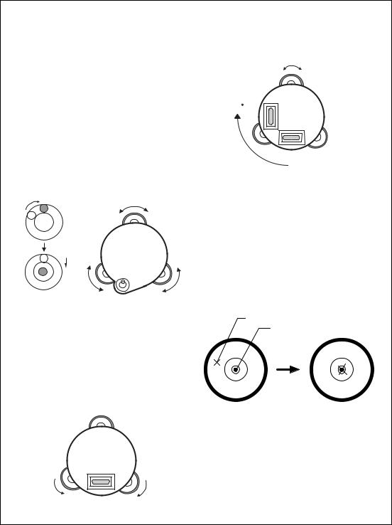
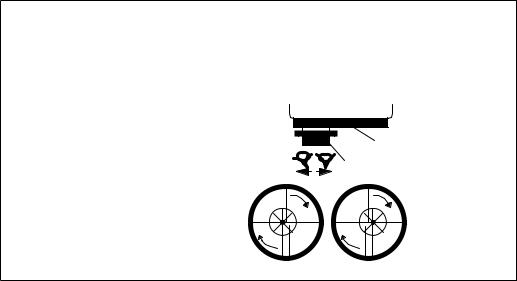
3. Roughly Leveling the Instrument by Using the Circular Level
1Turn the leveling screws A and B to move the bubble in the circular level. The bubble is now located on a line perpendicular to a line running through the centers of the two leveling screws being adjusted.
Leveling screw C
Leveling |
Leveling screw B |
|
screw A |
||
|
2Turn the leveling screw C to bring the bubble to the center of the circular level.
4. Centering by Using the Plate Level
1Rotate the instrument horizontally by using the Horizontal motion/clamp screw and place the plate level parallel with the line connecting leveling screws A and B, and then bring the bubble to the center of the plate level by turning leveling screws A and B.
2Rotate the instrument 90° (100gon) around its vertical axis and turn the remaining leveling screw or C to center the bubble once more.
Leveling screw C
90
90°
3Repeat the procedures 1 and 2 for each 90° (100gon) rotation of the instrument and check whether the bubble is correctly centered for all four points.
5.Centering by Using the Optical Plummet Telescope
Adjust the eyepiece of the optical plummet telescope to your eyesight.
Slide the instrument by loosening the tripod screw, place the point on the center mark, and then tighten the tripod screw. Sliding the instrument carefully not to rotate that allows you to get the least dislocation of the bubble.
Point
Center mark
Leveling  screw A
6. Completely Leveling the Instrument
Leveling the instrument precisely in a similar way to 4. Rotate the instrument and check to see that the bubble is in the center of the plate level regardless of telescope direction, then tighten the tripod screw hard.
 Leveling
screw B
2-2
2 PREPARATION FOR MEASUREMENT
2.3 Power Switch Key ON
1Confirm the instrument is leveled.
2Press the power key..
Press the power key
TOPCON GPT-2000
V : |
90°10'20" |
|
|
|
|
|
HR: |
0°00'00" |
|
|
|
|
Battery Power Remaining Display |
|
|
|
|
|
|
|
|
|
|
|
|
|
|
|
|
|
|
|
|
|
0SET |
HOLD |
HSET |
P1↓ |
|
||
|
|
|
|
|
|
|
●Confirm the battery power remaining display. Replace with charged battery or charge when battery level is low or indicates “Battery empty”. see Section 2.4“Battery Power Remaining Display” .
●Contrast adjustment
You can confirm prism constant value (PSM), non-prism constant value (NPM), atmospheric correction value (PPM) and you can also adjust the contrast of the display when the instrument is turned on.
To display this screen, see Chapter 16 “SELECTING MODE” .
CONTRAST ADJUSTMENT
PSM: 0.0 PPM 0.0
NPM: 0.0
↓ |
↑ |
- - - ENTER |
This enables you to adjust the brightness by pressing the [F1](↓) or [F2](↑) key.
To memorize the setting value after powering off, press [F4](ENTER) key.
2-3
2 PREPARATION FOR MEASUREMENT
2.4 Battery Power Remaining Display
Battery power remaining display indicates the power condition.
V : 90°10'20"
HR: 0°00'00"
0SET HOLD HSET P1↓
Battery power remaining display
Measurement is possible.
The power is poor. The battery should be recharged or replaced.
Blinking
<Battery empty> |
Measurement is impossible. |
Other displays disappear. |
Need to recharge or replace |
|
the battery. |
Note: 1 The battery operating time will vary depending on the environmental conditions such as ambient temperature, charging time, the number of times of charging and discharging etc. It is recommended for safety to charge the battery beforehand or to prepare spare full charged batteries.
2For general usage of the battery, see Chapter 14 “POWER SOURCE AND CHARGING” .
3The battery power remaining display shows the power level regarding to the measurement mode now operating.
The safety condition indicated by the battery power remaining display in the angle measurement mode does not necessarily assure the battery’s ability to be used in the distance measurement mode.
It may happen that the mode change from the angle mode to the distance mode will stop the operation because of insufficient battery power for the distance mode which consumes more power than angle mode.
2-4

2 PREPARATION FOR MEASUREMENT
2.5 Vertical and Horizontal Angle Tilt Correction
(GPT-2009 has vertical angle tilt correction only.)
When the tilt sensors are activated, automatic correction of vertical and horizontal angle for mislevelment is displayed.
To ensure a precise angle measurement, tilt sensors must be turned on. The display can also be used to fine level the instrument. If the (TILT OVER) display appears the instrument is out of automatic compensation range and must be leveled manually.
|
Zenith |
|
Zenith |
|
|
Standing axis |
Inclination of the standing |
|
Standing axis |
||
axis in the Y direction |
||
Inclination of the standing |
||
axis in the X direction |
|
|
Horizontal |
Trunnion axis |
|
|
●GPT-2000 compensates both the vertical angle and the horizontal angle readings due to inclination of the standing axis in the X and Y directions .
●For more information about dual axis compensation, refer to APPENDIX 1 “Dual Axis Compensation”.
When the instrument is out of compensation. (TILT OVER)
V : |
° |
' " |
|
V : |
° |
' " |
|
V : |
° |
' |
" |
HR: |
° |
' " |
|
HR: |
° |
' " |
|
HR: |
° |
' |
" |
<X TILT OVER> |
|
<Y TILT OVER> |
|
<XY TILT OVER> |
|||||||
|
|
|
|
|
|
|
|
|
|
|
|
Standing Axis in the X direction |
Standing Axis in the Y direction |
out of range |
out of range |
Standing Axis in the X and Y directions out of range
●The display of Vertical or Horizontal angle is unstable when instrument is on an unstable stage or a windy day. You can turn off the auto tilt correction function of V/H angle in this case.
●To set auto tilt correction from the moment that power is on, see Section 6.4.3“Vertical and Horizontal Angle Tilt correction ( Tilt ON/OFF)” .
2-5

2 PREPARATION FOR MEASUREMENT
●Setting Tilt Correction by Soft Key
To enable you to select tilt ON/OFF function. setting is not memorized after power is OFF.
[Example] Setting X,Y Tilt OFF
|
Operating procedure |
Option |
|
|
Display |
|
|
|
|
|
|
|
|
|
|
|
|
1 |
Press [F4] key to get the function page 2. |
|
|
|
|
|
|
|
[F4] |
|
V : |
90°10'20" |
|
|
|||
|
|
|
|
|
||||
|
|
|
|
HR: |
120°30'40" |
|
|
|
|
|
|
|
0SET |
HOLD HSET |
P1↓ |
|
|
|
|
|
|
|
|
|
|
|
|
|
|
|
TILT |
REP |
V% |
P2↓ |
|
2 |
Press [F1](TILT) key. |
|
|
|
|
|
|
|
|
|
|
|
|
|
|
||
[F1] |
|
TILT SENSOR:[XY-ON] |
|
|||||
|
In case ON is already selected, the display shows |
|
|
|||||
|
|
|
X:-0°00'25" |
|
|
|
||
|
tilt correction value. |
|
|
|
|
|
||
|
|
|
Y: 0°00'20" |
|
|
|
||
|
|
|
|
|
|
|
||
|
|
|
|
X-ON XY-ON OFF --- |
|
|||
3 |
Press [F3](OFF) key. |
|
|
|
|
|
|
|
|
|
|
|
|
|
|
||
[F3] |
|
TILT SENSOR: |
[OFF] |
|
||||
|
|
|
|
|||||
|
|
|
|
X-ON XY-ON OFF --- |
|
|||
4 |
Press [ESC] key. |
|
|
|
|
|
|
|
|
|
|
|
|
|
|
||
[ESC] |
|
V : |
90°10'20" |
|
|
|||
|
|
|
|
|
||||
|
|
|
|
HR: |
120°30'40" |
|
|
|
|
|
|
|
TILT |
REP |
V% |
P2↓ |
|
|
|
|
|
|
|
|
|
|
|
|
|
|
|
|
|
|
|
● The setting mode performed here will not be memorized after powering OFF. To set TILT correction in the initialized setting ( it is memorized after powering OFF), see Section 6.4.3“Vertical and Horizontal Angle Tilt correction ( Tilt ON/OFF)” .
2-6
2 PREPARATION FOR MEASUREMENT
2.6 How to Enter Alphanumeric characters
This enables you to enter alphanumeric characters such as the instrument height, prism height, occupied point, backsight point etc..
● How to select a item
[Example setting] Occupied point in the data collection mode.
The arrow indicates a item to enter.
The arrow line moves up or down when the [  ] key or [
 ] key is pressed.
[  ] or
] or
[ ]
]
PT# |
→ST-01 |
|
ID |
: |
|
INS.HT: |
0.000 m |
|
INPUT SRCH REC OCNEZ |
||
|
|
|
|
|
|
PT# |
:ST-01 |
|
ID |
→ |
|
INS.HT: 0.000 m |
||
INPUT SRCH REC OCNEZ |
||
|
|
|
|
|
|
PT# |
:ST-01 |
|
ID |
: |
|
INS.HT→ 0.000 m
INPUT SRCH REC OCNEZ
● How to enter characters
1Move the arrow to enter a item using the [  ] or [
 ] key.
2Press the [F1] (INPUT) key.
The arrow changes to the equal (=) .
The characters are displayed on the bottom line.
3 Press the [  ] or [
 ] key to select a page.
PT# |
→ |
ID |
: |
INS.HT: 0.000 m |
|
INPUT SRCH REC OCNEZ |
|
|
|
|
|
PT# |
= |
ID |
: |
INS.HT: 0.000 m 1234 5678 90.- [ENT]
ABCD EFGH IJKL [ENT]
MNOP QRST UVWX [ENT]
YZ+#[SPC][CLR][ENT]
4Press the soft key to select a group of characters.
Example: [F2](QRST) key is pressed.
[F1] |
[F2] |
[F3] |
[F4] |
|
|
|
|
PT# |
= |
|
|
ID |
: |
|
|
INS.HT: 0.000 m |
|
||
(Q) |
(R) |
(S) |
(T) |
|
|
|
|
[F1] [F2] [F3] [F4]
2-7

5Press soft key to select a character.
Example: [F4](T) key is pressed.
Select next character in the same manner.
6Press [F4](ENT) key.
The arrow moves to next item.
Select next character in the same manner.
2 PREPARATION FOR MEASUREMENT
PT# |
=T |
|
|
ID |
: |
|
|
INS.HT: |
0.000 m |
|
|
MNOP QRST UVWX [ENT] |
|||
|
|
|
|
|
|
|
|
PT# |
=TOPCON-1 |
|
|
ID |
: |
|
|
INS.HT |
: |
0.000 |
m |
MNOP QRST UVWX [ENT] |
|||
|
|
|
|
|
|
|
|
PT# |
:TOPCON-1 |
|
|
ID |
→ |
|
|
INS.HT |
: |
0.000 |
m |
INPUT SRCH REC OCNEZ
●To correct a character, move the cursor to correct character by pressing [ ] or [
  ] key and enter again.
2.7Point Guide (Only for Point Guide type)
Fast and simple to use, the Point Guide feature is useful when doing stake out work. The LED’s for the
Point Guide System on the instrument telescope assist the rod person to get on-line. When using the Point Guide System, the battery life will be approximately 8 hours at +20 °C (+68 °F).
Turning the Point Guide ON and Operation:
Press the [MENU] key to get the menu screen and press the |
Instrument |
[MENU] key again. Point Guide LED’s will be turned ON. Looking at the objective lens of the telescope, the right LED will blink and the left LED will stay lit.
The Point Guide should be used within a distance of 100 meters (328 feet). The quality of its results will depend on the weather conditions and the user’s eyesight.
The goal of the rod person is to look at both LED’s on the instrument and move the prism on-line until both LED’s are equally bright.
●If the solid LED is brighter, move right.
●If the blinking LED is brighter, move left.
Illuminate Blink
Prism
Once you have determined that both of the LED's are equally bright, you are on-line with the instrument.
Turning the Point Guide OFF:
To turn OFF the Point Guide System, press the [MENU] key again in menu screen.
The point guide function can be available while executing Layout mode. See 8.2 “Executing a Layout”.
2-8
2 PREPARATION FOR MEASUREMENT
2.8 Laser Plummet ON/OFF (Only for Laser Plummet type)
Laser plummet option will help you to center the instrument easily onto the measurement point. There are two ways to turn on/off of laser plummet option as follows.
● On/Off of laser plummet option by Soft Key in Tilt Correction
Operating procedure |
Option |
|
Display |
|
|
|
|
|
|
|
|
1 Press the [F4] key to get the function page 2. |
|
|
|
|
|
[F4] |
V : |
90°10'20" |
|
|
|
|
|
|
|||
|
|
HR: |
120°30'40" |
|
|
|
|
0SET |
HOLD HSET |
P1↓ |
|
|
|
|
|
|
|
|
|
TILT |
REP V% |
P2↓ |
|
2 Press the [F1](TILT) key. |
|
|
|
|
|
|
|
|
|
|
|
[F1] |
TILT SENSOR:[XY-ON] |
|
|||
In case ON is already selected, the display shows |
|
||||
|
X:-0°00'25" |
|
|
||
tilt correction value. |
|
|
|
||
|
Y: 0°00'20" |
|
|
||
|
|
|
|
||
|
|
X-ON XY-ON OFF L.PL |
|
||
|
|
|
|
|
|
3 Press the [F4](L.PL) key. |
[F4] |
TILT SENSOR:[XY-ON] |
|
By pressing the [F4](L.PL) key, the laser plummet |
|||
|
X:-0°00'25" |
||
will be turned On / Off alternately. |
|
||
|
Y: 0°00'20" |
||
|
|
||
|
|
X-ON XY-ON OFF L.PL |
●Symbol mark while the laser is emitting.
The following symbol mark will appear at the right side of the second line.
TILT |
SENSOR:[XY-ON] |
Symbol mark |
|
X:-0°00'25" |
|||
|
|||
Y: 0°00'20" |
|
||
X-ON |
XY-ON OFF L.PL |
|
|
● On/Off of laser plummet option from MENU mode
Operating procedure |
Operation |
|
Display |
|
|
|
|
|
|
|
|
1 Press the [MENU] key. |
|
|
|
|
|
[MENU] |
|
MENU |
1/3 |
|
|
|
|
|
|||
|
|
|
F1:DATA COLLECT |
|
|
|
|
|
F2:LAYOUT |
|
|
|
|
|
F3:MEMORY MGR. P↓ |
|
|
2 Press the [F4](P↓) key to get the menu on page 2. |
|
|
|
|
|
|
|
|
|
|
|
[F4] |
|
MENU |
2/3 |
|
|
|
|
|
|||
|
|
|
F1:PROGRAMS |
|
|
|
|
|
F2:GRID FACTOR |
|
|
|
|
|
F3:LASER PLUMMET P↓ |
|
|
3 Press the [F3] key. |
|
|
|
|
|
|
|
|
|
|
|
[F3] |
|
LASER PLUMMET |
[OFF] |
|
|
|
|
|
|||
|
|
|
F1:ON |
|
|
|
|
|
F2:OFF |
|
|
4 Press the [F1] or [F2] key to turn on or off the laser |
|
|
|
|
|
[F1] or [F2] |
|
LASER PLUMMET |
[ON] |
||
plummet option. |
|
||||
|
|
F1:ON |
|
|
|
|
|
|
|
|
|
|
|
|
F2:OFF |
|
|
|
|
|
|
|
|
Laser Plummet auto-cut off function
The laser plummet will be turned off automatically after 1 to 99 minutes (Default :3 minutes). It is also possible to stop the auto-cut off function.
Refer to Chapter 16 “SELECTING MODE” to change the time or to invalidate the function.
2-9
3 ANGLE MEASUREMENT
3 ANGLE MEASUREMENT
3.1 Measuring Horizontal Angle Right and Vertical Angle
Make sure the mode is in Angle measurement.
Operating procedure |
Operation |
|
|
Display |
|
|
|
|
|
|
|
1 Collimate the 1st target (A). |
|
|
|
|
|
Collimate A |
|
V : |
90°10'20" |
|
|
|
|
|
|||
|
|
|
HR: 120°30'40" |
|
|
|
|
|
0SET HOLD HSET P1↓ |
|
|
2 Set horizontal angle of target A at 0° 00' 00". |
|
|
|
|
|
|
|
|
|
|
|
[F1] |
|
H ANGLE 0 SET |
|
||
Press the [F1](0 set) key and press the [F3](YES) |
|
|
|||
|
|
> OK? |
|
|
|
key. |
|
|
|
|
|
|
|
|
|
|
|
|
|
|
--- --- [YES][NO] |
|
|
|
[F3] |
|
|
|
|
|
|
|
|
|
|
|
|
V : |
90°10'20" |
|
|
|
|
|
|
||
|
|
|
HR: |
0°00'00" |
|
|
|
|
0SET HOLD HSET P1↓ |
|
|
3 Collimate the 2nd target (B). |
|
|
|
|
|
|
|
|
|
|
|
Collimate B |
|
V : |
98°36'20" |
|
|
The required V/H angle to target B will be |
|
|
|||
|
|
HR: 160°40'20" |
|
||
displayed. |
|
|
|
||
|
|
|
|
|
|
|
|
|
0SET HOLD HSET P1↓ |
|
|
|
|
|
|
|
|
|
|
|
|
|
|
|
|
|
|
|
|
Reference : How to Collimate
1Point the telescope toward the light. Turn the diopter ring and adjust the diopter so that the cross hairs are clearly observed.
(Turn the diopter ring toward you first and then backward to focus.)
2Aim the target at the peak of the triangle mark of the sighting collimator. Allow a certain space between the sighting collimator and yourself for collimating.
3Focus the target with the focusing knob.
*If parallax is created between the cross |
|
|
|
hairs and the target when viewing |
|
|
Focusing knob |
vertically or horizontally while looking |
|
|
Telescope eyepiece (Diopter ring) |
into the telescope, focusing is incorrect |
|
|
|
|
|
|
|
ordiopter adjustment is poor. This |
|
|
|
adversely affects precision in |
|
|
|
measurement or survey Eliminate the |
|
∞ |
∞ |
parallax by carefully focusing |
|
||
and using diopter adjustment. |
∞ |
|
∞ |
3-1
3 ANGLE MEASUREMENT
3.2 Switching Horizontal Angle Right/Left
Make sure the mode is Angle measurement.
Operating procedure |
Operation |
|
|
Display |
|
|
|
|
|
|
|
|
|
1 Press the [F4](↓) key twice to get the function |
|
|
|
|
|
|
[F4] |
|
V : |
90°10'20" |
|
|
|
on page 3. |
|
|
|
|||
twice |
|
HR: 120°30'40" |
|
|
||
|
|
|
|
|||
|
|
|
0SET |
HOLD HSET |
P1↓ |
|
|
|
|
|
|
|
|
|
|
|
TILT |
REP V% |
P2↓ |
|
|
|
|
|
|
|
|
|
|
|
H-BZ |
R/L CMPS |
P3↓ |
|
2 Press the [F2](R/L) key. |
|
|
|
|
|
|
|
|
|
|
|
|
|
[F2] |
|
V : |
90°10'20" |
|
|
|
The mode Horizontal angle Right (HR) |
|
|
|
|||
|
|
HL: 239°29'20" |
|
|
||
switches to (HL) mode. |
|
|
|
|
||
|
|
|
|
|
|
|
|
|
|
H-BZ |
R/L CMPS |
P3↓ |
|
3 Measure as HL mode. |
|
|
|
|
|
|
|
|
|
|
|
|
|
|
|
|
|
|
|
|
● Every time pressing the [F2](R/L) key, HR/HL mode switches. |
|
|
|
|
|
|
|
|
|
|
|
|
|
3.3 Measuring from the Required Horizontal Angle
3.3.1 Setting by Holding the Angle
Make sure the mode is angle measurement.
Operating procedure |
Operation |
|
|
Display |
|
|
|
|
|
|
|
1 Set the required horizontal angle, using |
|
|
|
|
|
Display angle |
|
V : |
90°10'20" |
|
|
Horizontal tangent screw |
|
|
|||
|
|
HR: 130°40'20" |
|
||
|
|
|
|
||
|
|
|
0SET HOLD HSET P1↓ |
|
|
2 Press the [F2](HOLD) key. |
|
|
|
|
|
|
|
|
|
|
|
[F2] |
|
H ANGLE HOLD |
|
||
|
|
|
|||
|
|
|
HR= 130°40'20" |
|
|
|
|
|
> SET ? |
|
|
|
|
|
--- --- [YES][NO] |
|
|
3 Collimate the target. |
Collimate |
|
|
|
|
|
|
|
|
||
|
|
|
|
|
|
4 Press the [F3](YES) key to finish holding the |
|
|
|
|
|
[F3] |
|
V : |
90°10'20" |
|
|
horizontal angle.*1) |
|
|
|||
|
|
HR: 130°40'20" |
|
||
The display turns back to normal angle |
|
|
|
||
|
|
|
|
|
|
measurement mode. |
|
|
0SET HOLD HSET P1↓ |
|
|
|
|
|
|
||
|
|
|
|
|
|
|
|
|
|
|
|
*1) To return to the previous mode, press the [F4](NO) key. |
|
|
|
|
|
|
|
|
|
|
|
3-2

3 ANGLE MEASUREMENT
3.3.2 Setting a Horizontal Angle from the Keys
Make sure the mode is Angle measurement.
Operating procedure |
Operation |
|
|
Display |
|
|
|
|
|
|
|
1 Collimate the target. |
|
|
|
|
|
Collimate |
|
V : |
90°10'20" |
|
|
|
|
|
|||
|
|
|
HR: 170°30'20" |
|
|
|
|
|
0SET HOLD HSET P1↓ |
|
|
2 Press the [F3](HSET) key. |
|
|
|
|
|
|
|
|
|
|
|
[F3] |
|
H ANGLE SET |
|
||
|
|
|
|||
|
|
|
HR: |
|
|
|
|
|
INPUT --- --- ENTER |
|
|
|
|
|
|
|
|
|
|
|
1234 5678 90.-[ENT] |
|
|
3 Input the required horizontal angle by |
|
|
|
|
|
|
|
|
|
|
|
[F1] |
|
V : |
90°10'20" |
|
|
using keys. *1) |
|
|
|||
70.4020 |
|
HR: |
70°40'20" |
|
|
|
|
|
|||
For example :70°40'20" |
[F4] |
|
|
|
|
|
|
0SET HOLD HSET P1↓ |
|
||
|
|
|
|
||
When completed, normal measuring from the |
|
|
|
|
|
|
|
|
|
|
|
required Horizontal angle is possible. |
|
|
|
|
|
|
|
|
|
|
|
*1) To enter Alphanumeric characters, see Section 2.6 “How to Enter Alphanumeric characters” . |
|||||
|
|
|
|
|
|
3.4 Vertical Angle Percent Grade(%) Mode
Make sure the mode is Angle measurement.
Operating procedure |
Operation |
|
|
Display |
|
|
|
|
|
|
|
|
|
|
|
1 Press the [F4](↓) key to get the function on page 2. |
|
|
|
|
|
|
|
[F4] |
|
V : |
90°10'20" |
|
|
||
|
|
|
|
||||
|
|
|
HR: 170°30'20" |
|
|
||
|
|
|
0SET HOLD HSET |
P1↓ |
|
||
|
|
|
|
|
|
|
|
|
|
|
TILT |
REP |
V% |
P2↓ |
|
2 Press the [F3](V%) key. *1) |
|
|
|
|
|
|
|
|
|
|
|
|
|
|
|
[F3] |
|
V : |
-0.30 |
% |
|
|
|
|
|
|
|
||||
|
|
|
HR: 170°30'20" |
|
|
||
|
|
|
TILT |
REP |
V% |
P2↓ |
|
|
|
|
|
|
|
|
|
|
|
|
|
|
|
|
|
*1) Every time pressing the [F3](V%) key, the display mode switches.
● When the measurement is carried out over ±45° (±100%) from the horizontal, the display shows <OVER>.
3-3

3 ANGLE MEASUREMENT
3.5Repetition Angle Measurement
●Repetition angle measurement can be done by horizontal angle right measurement mode.
Make sure the mode is Horizontal Angle Right measurement.
Operating procedure |
Operation |
|
|
Display |
|
|
|
|
|
|
|
|
|
|
|
1 Press the [F4](↓) key to get the function on page 2. |
|
|
|
|
|
|
|
[F4] |
|
V : |
90°10'20" |
|
|
||
|
|
|
|
||||
|
|
|
HR: 170°30'20" |
|
|
||
|
|
|
0SET HOLD HSET |
P1↓ |
|
||
|
|
|
|
|
|
|
|
|
|
|
TILT |
REP |
V% |
P2↓ |
|
2 Press the [F2](REP)key. |
|
|
|
|
|
|
|
|
|
|
|
|
|
|
|
[F2] |
|
REPETITION ANGLE |
|
||||
|
|
|
|||||
|
|
|
> OK? |
|
|
|
|
|
|
|
--- |
--- |
[YES][NO] |
|
|
3 Press the [F3](YES) key. |
|
|
|
|
|
|
|
|
|
|
|
|
|
|
|
[F3] |
|
REP-ANGLE |
COUNT[ 0] |
|
|||
|
|
|
|||||
|
|
|
Ht: |
0°00'00" |
|
||
|
|
|
Hm: |
|
|
|
|
|
|
|
0SET |
V/H |
REL HOLD |
|
|
4 Collimate the target A and press the [F1] (0SET) |
|
|
|
|
|
|
|
|
|
|
|
|
|
|
|
Collimate A |
|
REPETITION ANGLE |
|
||||
key. |
|
|
|||||
[F1] |
|
INITIALIZE |
|
|
|
||
|
|
|
|
|
|||
|
|
|
> OK? |
|
|
|
|
|
|
|
--- |
--- |
[YES][NO] |
|
|
5 Press the [F3] (YES) key. |
|
|
|
|
|
|
|
|
|
|
|
|
|
|
|
[F3] |
|
REP-ANGLE |
COUNT[ 0] |
|
|||
|
|
|
|||||
|
|
|
Ht: |
0°00'00" |
|
||
|
|
|
Hm: |
|
|
|
|
|
|
|
0SET |
V/H |
REL HOLD |
|
|
6 Collimate the target B using the horizontal clamp |
|
|
|
|
|
|
|
|
|
|
|
|
|
|
|
Collimate B |
|
REP-ANGLE |
COUNT[ 1] |
|
|||
and tangent screw. |
|
|
|||||
[F4] |
|
Ht: |
45°10'00" |
|
|||
Press the [F4](HOLD) key. |
|
|
|||||
|
|
Hm: |
45°10'00" |
|
|||
|
|
|
|
||||
|
|
|
0SET |
V/H |
REL HOLD |
|
|
7 Recollimate target A using the horizontal clamp |
|
|
|
|
|
|
|
|
|
|
|
|
|
|
|
Collimate A |
|
REP-ANGLE |
COUNT[ 1] |
|
|||
and tangent screw, and press the [F3](REL)key. |
|
|
|||||
[F3] |
|
Ht: |
45°10'00" |
|
|||
|
|
|
|||||
|
|
|
Hm: |
45°10'00" |
|
||
|
|
|
0SET |
V/H |
REL HOLD |
|
|
8 Recollimate target B using the horizontal clamp |
|
|
|
|
|
|
|
|
|
|
|
|
|
|
|
Collimate B |
|
REP-ANGLE |
COUNT[ 2] |
|
|||
and tangent screw, and press the [F4](HOLD) key. |
|
|
|||||
[F4] |
|
Ht: |
90°20'00" |
|
|||
|
|
|
|||||
|
|
|
Hm: |
45°10'00" |
|
||
|
|
|
0SET |
V/H |
REL HOLD |
|
|
9 Repeat 7 to 8 to measure the desired number of |
|
|
|
|
|
|
|
|
|
|
|
|
|
|
|
|
|
REP-ANGLE |
COUNT[ 4] |
|
|||
repetitions. |
|
|
|
||||
|
|
Ht: |
180°40'00" |
|
|||
|
|
|
|
||||
|
|
|
Hm: |
45°10'00" |
|
||
|
|
|
0SET |
V/H |
REL HOLD |
|
|
|
|
|
|
|
|||
|
|
|
[Example] 4 measurement |
||||
|
|
|
|
|
|
|
|
3-4
Loading...