


 Loading...
INSTRUCTION MANUAL
AUTO TRACKING TOTAL STATION
GTS-820A SERIES
GTS-821A
GTS-822A
GTS-823A
GTS-825A

FOREWORD
FOREWORD
Thank you for purchasing the TOPCON Auto Tracking Total Station, GTS-820A series. For the best performance of the instruments, please carefully read these instructions and keep them in a convenient location for future reference.
General Handling Precautions
Before starting work or operation, be sure to check that the instrument is functioning correctly with normal performance.
Do not submerge the instrument into water.
The instrument can not be submerged underwater.
The instrument is designed based on the International Standard IP54, therefore it is protected from the normal rainfall.
Setting the instrument on a tripod
When mounting the instrument on a tripod, use a wooden tripod when possible. The vibrations that may occur when using a metallic tripod can effect the measuring precision.
Installing the tribrach
If the tribrach is installed incorrectly, the measuring precision could be effected. Occasionally check the adjusting screws on the tribrach. Make sure the base fixing lever is locked and the base fixing screws are tightened.
TR-5 or TR-5P tribrach should be used for prism side when the traverse surveys is performed.
Guarding the instrument against shocks
When transporting the instrument, provide some protection to minimize risk of shocks. Heavy shocks may cause the measurement to be faulty.
Carrying the instrument
Always carry the instrument by its handgrip.
Exposing the instrument to extreme heat.
Do not leave the instrument in extreme heat for longer than necessary. It could adversely affect its performance.
Sudden changes of temperature
Any sudden change of temperature to the instrument or prism may result in a reduction of measuring distance range, i.e when taking the instrument out from a heated vehicle. Let instrument acclimate itself to ambient temperature.
Battery level check
Confirm battery level remaining before operating.
Memory back up
The instrument has a built in battery for memory back up. If the battery power is low, “Back up battery empty” will display. It is still possible to measure the distance and the angle, but the measured data and the parameter setting can be lost. Contact your dealer, to replace the battery.
Taking the battery out
It is recommended not to take the battery out during the power is on. All the data stored is possible gone at that time. So please do your assembling or taking the battery out after the power is off.
No responsibility
TOPCON Corporation has no responsibility for loss of data stored in the memory in case unexpected accidents.
1

FOREWORD
Rotating the instrument and telescope
Rotation of the instrument or telescope is driven electronically in normal operation. Do not disturb the rotation.
Storage in the case
Keep the telescope horizontally and turn the instrument to align its mark with the lower base mark (Storage mark). Keep its objective lens side downward. Storing it in the case in any other way may cause damage. Hold the hand grips and base with both hands, when taking the instrument out of the case, or putting the equipment in the case.
Maintenance for driving parts.
Every 4,000~5,000 hours operation in total, change grease of driving parts.
Contact your dealer or TOPCON Head Office for the maintenance.
2

FOREWORD
Display for Safe Use
In order to encourage the safe use of products and prevent any danger to the operator and others or damage to properties, important warnings are put on the products and inserted in the instruction manuals.
We suggest that everyone understand the meaning of the following displays and icons before reading the “Safety Cautions” and text
Display |
Meaning |
|
|
|
|
WARNING |
Ignoring or disregard of this display may lead to the danger of death or |
|
serious injury. |
||
|
||
|
|
|
CAUTION |
Ignoring or disregard of this display may lead to personal injury or phys- |
|
ical damage. |
||
|
||
|
|
•Injury refers to hurt, burn, electric shock, etc.
•Physical damage refers to extensive damage to buildings or equipment and furniture.
Safety Cautions
 WARNING
•There is a risk of fire, electric shock or physical harm if you attempt to disassemble or repair the instrument yourself.
This is only to be carried out by TOPCON or an authorized dealer, only!
•Cause eye injury or blindness.
Do not look at the sun through a telescope.
•Laser beams can be dangerous, and can cause eye injury's if used incorrectly.
Never attempt to repair the instrument yourself.
•Cause eye injury or blindness.
Do not stare into beam.
•High temperature may cause fire.
Do not cover the charger while it is charging.
•High temperature may cause fire.
Do not connect the battery to an instrument while it is charging.
•Risk of fire or electric shock.
Do not use damaged power cable, plug and socket.
•Risk of fire or electric shock.
Do not use a wet battery or charger.
•May ignite explosively.
Never use an instrument near flammable gas, liquid matter, and do not use in a coal mine.
•Battery can cause explosion or injury.
Do not dispose in fire or heat.
•Risk of fire or electric shock.
Do not use any power voltage except the one given on manufacturers instructions.
•Battery can cause outbreak of fire.
Do not use any other type of charger other than the one specified.
•Risk of fire.
Do not use any other power cable other than the one specified.
•Battery can cause outbreak of fire.
Do not block up the vent of the battery.
•The short circuit of a battery can cause a fire.
Do not short circuit battery when storing it.
3

FOREWORD
 CAUTION
Use of controls or adjustment or performance of procedures other than those specified herein may result in hazardous radiation exposure.
Let the laser beam reach the aimed object or the target without anybody else in the laser beam path. In case you operate laser beam open, avoid radiating laser beam to the height of man's head. It is quite possible for the beam to enter into one's eyes, and it is possible to lose visual sight temporarily, and lose one's caution and awareness of other dangers - avoid glaring beam.
Do not connect or disconnect equipment with wet hands, you are at risk of electric shocks if you do!
Risk of injury by overturn the carrying case.
Do not stand or sit on the carrying cases.
Please note that the tips of tripod can be hazardous, be aware of this when setting up or carrying the tripod.
Risk of injury by falling down the instrument or case.
Do not use a carrying case with a damaged which belts, grips or latches.
Do not allow skin or clothing to come into contact with acid from the batteries, if this does occur then wash off with copious amounts of water and seek medical advice.
A plumb bob can cause an injury to a person if used incorrectly.
It could be dangerous if the instrument falls over, please ensure you attach a handle battery to the instrument securely.
Ensure that you mount the Tribrach correctly, failing to do so may result in injury if the tribrach were to fall over.
It could be dangerous if the instrument falls over, please check that you fix the instrument to the tripod correctly.
Risk of injury by falling down a tripod and an instrument.
Always check that the screws of tripod are tightened.
User
1)This product is for professional use only!
The user is required to be a qualified surveyor or have a good knowledge of surveying, in order to understand the user and safety instructions, before operating, inspecting or adjusting.
2)Wear the required protectors (safety shoes, helmet, etc.) when operating.
Exceptions from Responsibility
1)The user of this product is expected to follow all operating instructions and make periodic checks of the product’s performance.
2)The manufacturer, or its representatives, assumes no responsibility for results of a faulty or intentional usage or misuse including any direct, indirect, consequential damage, and loss of profits.
3)The manufacturer, or its representatives, assumes no responsibility for consequential damage, and loss of profits by any disaster, (an earthquake, storms, floods etc.).
A fire, accident, or an act of a third party and/or a usage any other usual conditions.
4)The manufacturer, or its representatives, assumes no responsibility for any damage, and loss of profits due to a change of data, loss of data, an interruption of business etc., caused by using the product or an unusable product.
5)The manufacturer, or its representatives, assumes no responsibility for any damage, and loss of profits caused by usage except for explained in the user manual.
6)The manufacturer, or its representatives, assumes no responsibility for damage caused by wrong movement, or action due to connecting with other products.
4
FOREWORD
Laser Safety
GTS-820A series uses the visible laser beam for auto tracking, optical communication. The GTS-820A series products are manufactured and sold in accordance with “Radiation Safety of Laser Products, Equipment Classification, Requirements and User‘s Guide” (IEC Publication 60825-1) or “Performance Standards for Light-Emitting Products” (FDA/BRH 21 CFR 1040) provided on the safety standards for laser beam.
As per the said standards, GTS-820A series is classified as “Class 2 (CLASS II) Laser Products”. The laser beam belongs not very dangerous type but we request you to keep and understand “Safety standard for users” as mentioned in the manual instruction.
In case of any failure, do not disassemble the instrument. Contact TOPCON or your TOPCON dealer.
Laser class of each mode is as follows.
Mode |
Laser class |
|
|
Autotracking |
Class 1 (CLASS II) |
|
|
Optical communication |
Class 2 (CLASS II) |
|
|
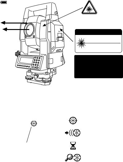
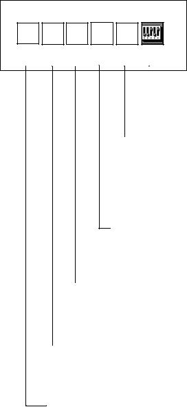
Labels
Find the labels which describes the caution and safety about the laser beam as follows in GTS-820A series.
We request you to replace it one anytime the caution labels are damaged or lost and paste a new one at the same place. You can get the labels from Topcon or your dealer.
Warning Label
Beam aperture
Explanatory Label
Beam aperture
C A U T I O N
LASER RADIATION-DO NOT
STARE INTO BEAM
WAVE LENGTH 660, 690nm
1mW MAXIMUM OUTPUT
DIODE LASER |
CLASS IILASER PRODUCT |
|||||
|
|
|
|
|
|
|
|
|
|
|
|
|
|
|
|
|
|
|
|
|
|
|
|
|
|
|
|
|
|
|
|
|
|
|
|
|
|
|
|
|
|
|
|
|
|
|
|
|
|
|
|
|
|
|
|
Each label is differed by the market.
GTS-820A series
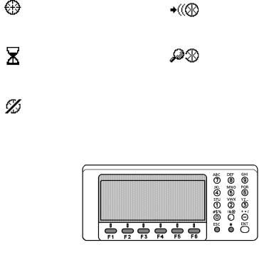
Symbol marks while the laser is emitting.
The following symbol marks of instrument status will indicate that the laser is emitting.
|
|
|
Marks |
Status of |
|
|
|
instrument |
|
V : |
87°55'45" |
|
|
|
|
|
|
||
|
|
Auto-collimating |
||
HR: 180°44'12" |
|
|
||
|
|
|
|
|
SD |
HD NEZ 0SET HOLD P1↓ |
|
|
Auto-tracking |
|
|
|
|
|
|
The symbol mark |
|
Waiting |
|
|
|
|
|
|
|
|
|
|
Searching |
|
|
|
|
|
5
FOREWORD
Contents
FOREWORD . . . . . . . . . . . . . . . . . . . . . . . . . . . . . . . . . . . . . . . . . . . . . . . . . . 1
General Handling Precautions . . . . . . . . . . . . . . . . . . . . . . . . . . . . . . . . . . . . . . . . . . . . . . . . 1 Display for Safe Use . . . . . . . . . . . . . . . . . . . . . . . . . . . . . . . . . . . . . . . . . . . . . . . . . . . . . . . 3 Safety Cautions . . . . . . . . . . . . . . . . . . . . . . . . . . . . . . . . . . . . . . . . . . . . . . . . . . . . . . . . . . . 3 User . . . . . . . . . . . . . . . . . . . . . . . . . . . . . . . . . . . . . . . . . . . . . . . . . . . . . . . . . . . . . . . . . . . . 4 Exceptions from Responsibility . . . . . . . . . . . . . . . . . . . . . . . . . . . . . . . . . . . . . . . . . . . . . . . 4 Laser Safety. . . . . . . . . . . . . . . . . . . . . . . . . . . . . . . . . . . . . . . . . . . . . . . . . . . . . . . . . . . . . . 5 Contents. . . . . . . . . . . . . . . . . . . . . . . . . . . . . . . . . . . . . . . . . . . . . . . . . . . . . . . . . . . . . . . . . 6 Standard Set Composition . . . . . . . . . . . . . . . . . . . . . . . . . . . . . . . . . . . . . . . . . . . . . . . . . . . 9
1 NOMENCLATURE AND FUNCTIONS . . . . . . . . . . . . . . . . . . . . . . . . . . 1-1
1.1 Nomenclature . . . . . . . . . . . . . . . . . . . . . . . . . . . . . . . . . . . . . . . . . . . . . . . . . . . . . . . . 1-1 1.2 Display . . . . . . . . . . . . . . . . . . . . . . . . . . . . . . . . . . . . . . . . . . . . . . . . . . . . . . . . . . . . . 1-3 1.3 Operating Key . . . . . . . . . . . . . . . . . . . . . . . . . . . . . . . . . . . . . . . . . . . . . . . . . . . . . . . . 1-4 1.4 Function Key (Soft Key) . . . . . . . . . . . . . . . . . . . . . . . . . . . . . . . . . . . . . . . . . . . . . . . . 1-5 1.5 Star key (*key) mode . . . . . . . . . . . . . . . . . . . . . . . . . . . . . . . . . . . . . . . . . . . . . . . . . . 1-7 1.6 Auto Power Off . . . . . . . . . . . . . . . . . . . . . . . . . . . . . . . . . . . . . . . . . . . . . . . . . . . . . . 1-11 1.7 Data Output. . . . . . . . . . . . . . . . . . . . . . . . . . . . . . . . . . . . . . . . . . . . . . . . . . . . . . . . . 1-11 1.8 Rotating Method . . . . . . . . . . . . . . . . . . . . . . . . . . . . . . . . . . . . . . . . . . . . . . . . . . . . . 1-11
1.8.1 Rotating by H/V Shuttle and H/V Jog . . . . . . . . . . . . . . . . . . . . . . . . . . . . . . . . . 1-11 1.8.2 Auto Inversion . . . . . . . . . . . . . . . . . . . . . . . . . . . . . . . . . . . . . . . . . . . . . . . . . . 1-11 1.8.3 Rotating automatically to a required Horizontal and Vertical angle . . . . . . . . . . 1-11 1.9 Using together with RC-2II Remote Control System. . . . . . . . . . . . . . . . . . . . . . . . . . 1-12 1.10 Using connecting with Personal Computer (PC). . . . . . . . . . . . . . . . . . . . . . . . . . . . 1-13
2 PREPARATION FOR MEASUREMENT . . . . . . . . . . . . . . . . . . . . . . . . . 2-1
2.1 Power Connection. . . . . . . . . . . . . . . . . . . . . . . . . . . . . . . . . . . . . . . . . . . . . . . . . . . . . 2-1 2.2 Setting Instrument Up For Measurement . . . . . . . . . . . . . . . . . . . . . . . . . . . . . . . . . . . 2-2 2.3 Power Switch Key ON. . . . . . . . . . . . . . . . . . . . . . . . . . . . . . . . . . . . . . . . . . . . . . . . . . 2-3 2.4 Battery Level Indicator . . . . . . . . . . . . . . . . . . . . . . . . . . . . . . . . . . . . . . . . . . . . . . . . . 2-4 2.5 Main Menu Icons. . . . . . . . . . . . . . . . . . . . . . . . . . . . . . . . . . . . . . . . . . . . . . . . . . . . . . 2-5 2.6 Vertical and Horizontal Angle Tilt Correction . . . . . . . . . . . . . . . . . . . . . . . . . . . . . . . . 2-6 2.7 Compensation of Systematic Error of Instrument . . . . . . . . . . . . . . . . . . . . . . . . . . . . . 2-7 2.8 Resume Mode ON/OFF . . . . . . . . . . . . . . . . . . . . . . . . . . . . . . . . . . . . . . . . . . . . . . . . 2-8 2.9 How to Enter Numerals and Alphabet Letters. . . . . . . . . . . . . . . . . . . . . . . . . . . . . . . . 2-8 2.10 Memory Card . . . . . . . . . . . . . . . . . . . . . . . . . . . . . . . . . . . . . . . . . . . . . . . . . . . . . . . 2-9 2.11 Inclination of Prism and Measuring Error . . . . . . . . . . . . . . . . . . . . . . . . . . . . . . . . . 2-10
3 AUTOMATIC TRACKING / AUTOMATIC COLLIMATION . . . . . . . . . . 3-1
3.1 Automatic Tracking . . . . . . . . . . . . . . . . . . . . . . . . . . . . . . . . . . . . . . . . . . . . . . . . . . . . 3-1 3.2 Automatic Collimation . . . . . . . . . . . . . . . . . . . . . . . . . . . . . . . . . . . . . . . . . . . . . . . . . . 3-3 3.3 Range of Laser for Auto-tracking and Auto-collimating . . . . . . . . . . . . . . . . . . . . . . . . 3-4 3.4 Setting Parameters for Auto-Tracking. . . . . . . . . . . . . . . . . . . . . . . . . . . . . . . . . . . . . . 3-5 3.4.1 Setting Items . . . . . . . . . . . . . . . . . . . . . . . . . . . . . . . . . . . . . . . . . . . . . . . . . . . . 3-5 3.4.2 How to set the parameters . . . . . . . . . . . . . . . . . . . . . . . . . . . . . . . . . . . . . . . . . . 3-7
4 STANDARD MEASUREMENT MODE . . . . . . . . . . . . . . . . . . . . . . . . . . 4-1
4.1 Angle Measurement . . . . . . . . . . . . . . . . . . . . . . . . . . . . . . . . . . . . . . . . . . . . . . . . . . . 4-1 4.1.1 Measuring Horizontal Angle Right and Vertical Angle . . . . . . . . . . . . . . . . . . . . . 4-1 4.1.2 Switching Horizontal Angle Right/Left . . . . . . . . . . . . . . . . . . . . . . . . . . . . . . . . . 4-2 4.1.3 Measuring from the Required Horizontal Angle . . . . . . . . . . . . . . . . . . . . . . . . . . 4-2 4.1.4 Vertical Angle Percent Grade(%) Mode . . . . . . . . . . . . . . . . . . . . . . . . . . . . . . . . 4-3 4.1.5 Automatic Rotation to a Required Horizontal and Vertical Absolute Angle . . . . . 4-4
4.2 Distance Measurement . . . . . . . . . . . . . . . . . . . . . . . . . . . . . . . . . . . . . . . . . . . . . . . . . 4-5 4.2.1 Setting of the Atmospheric Correction . . . . . . . . . . . . . . . . . . . . . . . . . . . . . . . . . 4-5 4.2.2 Setting of the Correction for Prism Constant . . . . . . . . . . . . . . . . . . . . . . . . . . . . 4-5 4.2.3 Distance Measurement (Continuous Measurement) . . . . . . . . . . . . . . . . . . . . . . 4-5 4.2.4 Distance Measurement (Single/N-times Measurement) . . . . . . . . . . . . . . . . . . . . 4-6 4.2.5 Fine / Coarse Measuring Mode . . . . . . . . . . . . . . . . . . . . . . . . . . . . . . . . . . . . . . 4-8 4.2.6 Stake Out (S-O) . . . . . . . . . . . . . . . . . . . . . . . . . . . . . . . . . . . . . . . . . . . . . . . . . . 4-9
4.3 COORDINATE MEASUREMENT . . . . . . . . . . . . . . . . . . . . . . . . . . . . . . . . . . . . . . . . 4-10 4.3.1 Setting Coordinate Values of Occupied Point . . . . . . . . . . . . . . . . . . . . . . . . . . 4-10 4.3.2 Setting of the Instrument Height / Prism Height . . . . . . . . . . . . . . . . . . . . . . . . . 4-12 4.3.3 Execution of Coordinate Measuring . . . . . . . . . . . . . . . . . . . . . . . . . . . . . . . . . . 4-13
6
FOREWORD
4.4 DATA OUTPUT . . . . . . . . . . . . . . . . . . . . . . . . . . . . . . . . . . . . . . . . . . . . . . . . . . . . . 4-15
5 PROGRAM MODES . . . . . . . . . . . . . . . . . . . . . . . . . . . . . . . . . . . . . . . . 5-1
5.1 Setting a Direction Angle for Backsight Orientation . . . . . . . . . . . . . . . . . . . . . . . . . . . 5-2 5.2 Retaining a Coordinate (STORENEZ) . . . . . . . . . . . . . . . . . . . . . . . . . . . . . . . . . . . . 5-3 5.3 Remote Elevation measurement (REM). . . . . . . . . . . . . . . . . . . . . . . . . . . . . . . . . . . . 5-5 5.4 Missing Line Measurement (MLM) . . . . . . . . . . . . . . . . . . . . . . . . . . . . . . . . . . . . . . . . 5-8 5.5 Line Measurement (LINE). . . . . . . . . . . . . . . . . . . . . . . . . . . . . . . . . . . . . . . . . . . . . . 5-11 5.6 Offset measurement (OFFSET) . . . . . . . . . . . . . . . . . . . . . . . . . . . . . . . . . . . . . . . . . 5-14
5.6.1 Angle Offset . . . . . . . . . . . . . . . . . . . . . . . . . . . . . . . . . . . . . . . . . . . . . . . . . . . . 5-15 5.6.2 Distance Offset Measurement . . . . . . . . . . . . . . . . . . . . . . . . . . . . . . . . . . . . . . 5-17 5.6.3 Plane Offset Measurement . . . . . . . . . . . . . . . . . . . . . . . . . . . . . . . . . . . . . . . . 5-19 5.6.4 Column Offset Measurement . . . . . . . . . . . . . . . . . . . . . . . . . . . . . . . . . . . . . . . 5-21 5.7 External Link. . . . . . . . . . . . . . . . . . . . . . . . . . . . . . . . . . . . . . . . . . . . . . . . . . . . . . . . 5-23 5.7.1 Starting compatible communication program of AP-L1A . . . . . . . . . . . . . . . . . . 5-23 5.7.2 Setting for the communication . . . . . . . . . . . . . . . . . . . . . . . . . . . . . . . . . . . . . . 5-23 5.7.3 Carrying out Communication . . . . . . . . . . . . . . . . . . . . . . . . . . . . . . . . . . . . . . . 5-27
6 MEMORY MANAGE MODES . . . . . . . . . . . . . . . . . . . . . . . . . . . . . . . . . 6-1
6.1 View Internal Memory and Card Memory Status . . . . . . . . . . . . . . . . . . . . . . . . . . . . . 6-1 6.2 Protect a File. . . . . . . . . . . . . . . . . . . . . . . . . . . . . . . . . . . . . . . . . . . . . . . . . . . . . . . . . 6-2 6.3 Rename a File . . . . . . . . . . . . . . . . . . . . . . . . . . . . . . . . . . . . . . . . . . . . . . . . . . . . . . . 6-2 6.4 Deleting a File. . . . . . . . . . . . . . . . . . . . . . . . . . . . . . . . . . . . . . . . . . . . . . . . . . . . . . . . 6-3 6.5 Copy a File . . . . . . . . . . . . . . . . . . . . . . . . . . . . . . . . . . . . . . . . . . . . . . . . . . . . . . . . . . 6-3 6.6 Initializing Memory . . . . . . . . . . . . . . . . . . . . . . . . . . . . . . . . . . . . . . . . . . . . . . . . . . . . 6-4
7 COMMUNICATION MODES . . . . . . . . . . . . . . . . . . . . . . . . . . . . . . . . . . 7-1
7.1 Setting of PROTOCOL . . . . . . . . . . . . . . . . . . . . . . . . . . . . . . . . . . . . . . . . . . . . . . . . . 7-1 7.2 Data File In . . . . . . . . . . . . . . . . . . . . . . . . . . . . . . . . . . . . . . . . . . . . . . . . . . . . . . . . . . 7-2 7.3 Data File Out. . . . . . . . . . . . . . . . . . . . . . . . . . . . . . . . . . . . . . . . . . . . . . . . . . . . . . . . . 7-2
8 |
PARAMETERS SETTING MODE . . . . . . . . . . . . . . . . . . . . . . . . . . . . . . |
8-1 |
||
|
8.1 |
Parameter Setting Options . . . . . . . . . . . . . . . . . . . . . . . . . . . . . . . . . . . . . . . . . . . . . . |
8-1 |
|
|
|
8.1.1 |
Parameters for Measurement and Display . . . . . . . . . . . . . . . . . . . . . . . . . . . . . |
8-1 |
|
|
8.1.2 |
Parameters for communication . . . . . . . . . . . . . . . . . . . . . . . . . . . . . . . . . . . . . . |
8-3 |
|
8.2 |
Setting Parameters. . . . . . . . . . . . . . . . . . . . . . . . . . . . . . . . . . . . . . . . . . . . . . . . . . . . |
8-5 |
|
|
|
8.2.1 |
Parameters for Measurement and Display . . . . . . . . . . . . . . . . . . . . . . . . . . . . . |
8-5 |
|
|
8.2.2 |
Parameters for Communication . . . . . . . . . . . . . . . . . . . . . . . . . . . . . . . . . . . . . . |
8-6 |
|
|
8.2.3 |
Password Option . . . . . . . . . . . . . . . . . . . . . . . . . . . . . . . . . . . . . . . . . . . . . . . . . |
8-6 |
9 |
CHECK AND ADJUSTMENT . . . . . . . . . . . . . . . . . . . . . . . . . . . . . . . . . |
9-1 |
||
9.1 Checking and Adjusting of Instrument Constant. . . . . . . . . . . . . . . . . . . . . . . . . . . . . . 9-1 9.2 Checking the Optical Axis. . . . . . . . . . . . . . . . . . . . . . . . . . . . . . . . . . . . . . . . . . . . . . . 9-2 9.3 Checking/Adjusting the Theodolite Functions. . . . . . . . . . . . . . . . . . . . . . . . . . . . . . . . 9-4 9.3.1 Checking /Adjusting the Plate Level . . . . . . . . . . . . . . . . . . . . . . . . . . . . . . . . . . 9-5 9.3.2 Checking /Adjusting the Circular Level . . . . . . . . . . . . . . . . . . . . . . . . . . . . . . . . 9-5 9.3.3 Adjustment of the Vertical Cross-hair . . . . . . . . . . . . . . . . . . . . . . . . . . . . . . . . . 9-6 9.3.4 Collimation of the Instrument . . . . . . . . . . . . . . . . . . . . . . . . . . . . . . . . . . . . . . . . 9-7 9.3.5 Checking / Adjusting the Optical Plummet Telescope . . . . . . . . . . . . . . . . . . . . . 9-8 9.4 Adjustment of Compensation Systematic Error of Instrument . . . . . . . . . . . . . . . . . . . 9-9
9.5 Showing Constant List and Switch ON/OFF
Compensation Systematic Error of Instrument. . . . . . . . . . . . . . . . . . . . . . . . . . . . . 9-11 9.6 How to adjust the date and time . . . . . . . . . . . . . . . . . . . . . . . . . . . . . . . . . . . . . . . . . 9-12 9.7 How to Set the Instrument Constant Value. . . . . . . . . . . . . . . . . . . . . . . . . . . . . . . . . 9-13 9.8 Reference Frequency Checking Mode . . . . . . . . . . . . . . . . . . . . . . . . . . . . . . . . . . . . 9-14 9.9 Inspection and Adjustment of Optic Axis for Auto -Tracking. . . . . . . . . . . . . . . . . . . . 9-15
10 SETTING THE PRISM CONSTANT VALUE. . . . . . . . . . . . . . . . . . . . 10-1 11 SETTING ATMOSPHERIC CORRECTION . . . . . . . . . . . . . . . . . . . . 11-1
11.1 Calculation of Atmospheric Correction. . . . . . . . . . . . . . . . . . . . . . . . . . . . . . . . . . . 11-1 11.2 Setting of Atmospheric Correction Value . . . . . . . . . . . . . . . . . . . . . . . . . . . . . . . . . 11-1
12 CORRECTION FOR REFRACTION AND EARTH CURVATURE . . . 12-1
12.1 Distance Calculation Formula. . . . . . . . . . . . . . . . . . . . . . . . . . . . . . . . . . . . . . . . . . 12-1
13 POWER SOURCE AND CHARGING . . . . . . . . . . . . . . . . . . . . . . . . . 13-1
13.1 Rechargeable Battery BT-56Q . . . . . . . . . . . . . . . . . . . . . . . . . . . . . . . . . . . . . . . . . 13-1
7
FOREWORD
14 DETACH/ATTACH OF TRIBRACH. . . . . . . . . . . . . . . . . . . . . . . . . . . 14-1 15 BATTERY SYSTEM. . . . . . . . . . . . . . . . . . . . . . . . . . . . . . . . . . . . . . . 15-1 16 PRISM SYSTEM . . . . . . . . . . . . . . . . . . . . . . . . . . . . . . . . . . . . . . . . . 16-1 17 PRECAUTIONS . . . . . . . . . . . . . . . . . . . . . . . . . . . . . . . . . . . . . . . . . . 17-1 18 ERROR DISPLAYS . . . . . . . . . . . . . . . . . . . . . . . . . . . . . . . . . . . . . . . 18-1 19 SPECIAL ACCESSORIES. . . . . . . . . . . . . . . . . . . . . . . . . . . . . . . . . . 19-1 20 SPECIFICATIONS . . . . . . . . . . . . . . . . . . . . . . . . . . . . . . . . . . . . . . . . 20-1 APPENDIX . . . . . . . . . . . . . . . . . . . . . . . . . . . . . . . . . . . . . . . . . APPENDIX-1
Dual Axis Compensation..................................................................................... |
APPENDIX-1 |
Precaution when Charging or Storing Batteries.................................................. |
APPENDIX-3 |
8
FOREWORD
Standard Set Composition
The numerical value in parentheses shows the quantity.
GTS-820A series (with lens cap) (1) |
Plastic carrying case (1) |
||
|
|
|
|
Battery BT-56Q (2) |
Battery charger BC-27BR or BC-27CR (1) |
Sun shade (1) |
Plastic rain cover (1) |
Plumb bob set (1) |
Tool kit with case [ rod pins, Plumb bob hook, screw- |
|
driver, cleaning brush ] (1) |
Plumb bob hook is included in the tool kit case.
Instruction manual (1)
(Make sure that all of the above items are with the instrument when purchased.)
Remarks:
1)Battery charger BC-27CR is for AC 230V use and BC-27BR is for AC 120V use.
2)Plumb bob set and plumb bob hook are supplied for certain markets.
9

1 NOMENCLATURE AND FUNCTIONS
1NOMENCLATURE AND FUNCTIONS
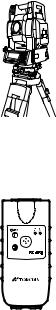
1.1Nomenclature
Sighting collimator
Handle
Laser aperture (for optical communication)
Objective lens Laser aperture (for auto-tracking)
Tracking indicator
Optical plummet telescope
Display window
(Only for GTS-821A)
Operation keys
(Only for GTS-821A)
Handle fixing knob
Instrument height mark
Instrument center mark
Card cover lever
Battery BT-56Q
Power supply connector
Serial Signal
Connector-1(6pin)
Leveling screw
Base fixing screw |
|
Base (Model TR-5) |
The caution labels are pasted up GTS-820A series which describe the warning of laser beam. Refer to "Laser Safety" about label positions and their shapes.
1-1
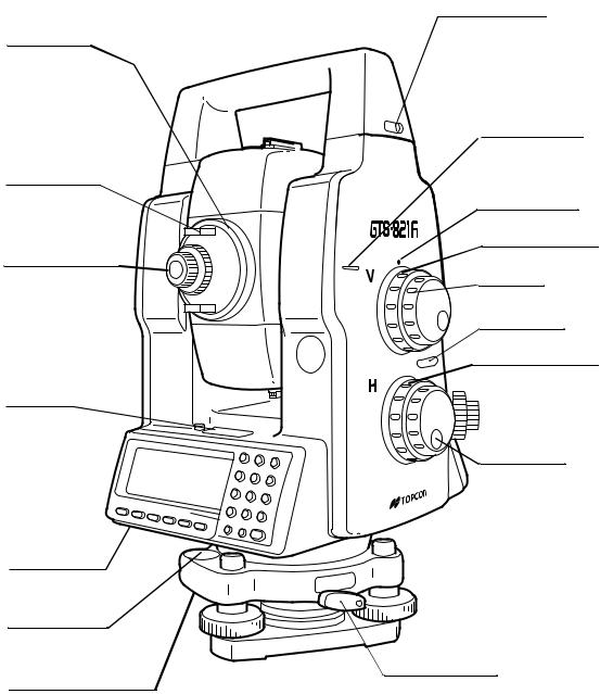
Telescope
focusing knob
Telescope grip
Telescope eyepiece
Plate level
Centronics connector
Circular level
Adjusting screws for circular level
1 NOMENCLATURE AND FUNCTIONS
Handle fixing knob
Instrument height mark
Instrument center mark
Vertical shuttle
Vertical jog
Power switch
Horizontal shuttle
Horizontal jog
Tribrach fixing lever
1-2

1 NOMENCLATURE AND FUNCTIONS
1.2Display
•Display
In general upper four lines display the measuring data, and the
bottom line displays the soft key function which is changed by the measuring mode.
•Contrast
The contrast and illumination of display window are adjusted by star (H) key.
•Heater (Automatic)
The built-in heater keeps the display functional when the temperature goes below 0°C (32 °F).To switch the heater ON or OFF, refer to Chapter 8 “PARAMETERS SETTING MODE”.
When the heater is ON and the temperature goes below 0°C.(32 °F), the heater automatically adjust the temperature to the display to keep it operating.
•Example
V : 87°55'45"
HR: 180°44'12"
SD HD NEZ 0SET HOLD P1↓
Angle measurement mode
V-angle : 87°55’20”
H-angle : 180°44’12”
V : 87°55'40"
HR: 180°44'12" PSM 0.0
SD: |
12.345 |
PPM |
0.0 |
|
|
(m) *F.R |
|
MEAS |
MODE VH |
HD |
NEZ P1↓ |
|
|||
Distance measurement mode |
|||
Horizontal-angle |
87°55’40”: |
||
Horizontal distance : |
180°44’12” |
||
Relative elevation |
:12.345m |
||
•Display marks
Display |
Contents |
Display |
Content |
|
|
|
|
V |
V-angle |
* |
EDM working |
|
|
|
|
V% |
Percent grade |
(m) |
Meter unit |
|
|
|
|
HR |
H-angle right |
(f) |
Feet unit |
|
|
|
|
HL |
H-angle left |
F |
Fine mode |
|
|
|
|
HD |
Horizontal distance |
C |
Coarse mode (1mm) |
|
|
|
|
VD |
Relative elevation |
T |
Tracking mode (10mm) |
|
|
|
|
SD |
Slope distance |
R |
Repeat measurement |
|
|
|
|
N |
N coordinate |
S |
Single measurement |
|
|
|
|
E |
E coordinate |
N |
N-times measurement |
|
|
|
|
Z |
Z coordinate |
ppm |
Atmospheric correction value |
|
|
|
|
|
|
psm |
Prism constant value |
|
|
|
|
|
|
|
|
|
Battery Level Indicator |
|
Rotation Indicator |
|
Refer to Section 2.4 “Battery Level |
|
Refer to Section 1.8 “Rotating |
|
Indicator” for further information. |
|
Method” for further information. |
|
|
|
|
1-3
|
|
|
|
1 NOMENCLATURE AND FUNCTIONS |
|
l The symbol marks for Auto-tracking and Auto-collimating |
|||||
|
|
|
|
|
|
|
Auto-collimating |
|
|
Auto-tracking |
|
|
(Laser is emitting) |
|
|
(Laser is emitting) |
|
|
GTS-820A series is in auto- |
|
|
GTS-820A series is in auto- |
|
|
collimating status. |
|
|
tracking status. |
|
|
|
|
|
|
|
|
Waiting (Laser is emitting) |
|
|
Searching (Laser is emitting) |
|
|
GTS-820A series is in waiting |
|
|
GTS-820A series is searching a |
|
|
status. |
|
|
prism. |
|
|
|
|
|
|
|
|
Failure in auto-collimating. |
|
|
|
|
|
(Laser is off) |
|
|
|
|
|
GTS-820A series could not find |
|
|
|
|
|
the target prism during auto- |
|
|
|
|
|
collimating. |
|
|
|
|
|
|
|
|
|
|
1.3 Operating Key
KEY |
NAME |
FUNCTION |
|
|
|
|
|
F1~F6 |
Soft key |
Functions are according to the displayed message. |
|
|
|
|
|
0~9 . - |
Numeric key |
Numeric Character Entry for Preset Data |
|
|
|
|
|
A ~/ |
Alpha key |
Alpha Character Entry |
|
|
|
|
|
ESC |
Escape key |
Escape to Previous Display or Menu |
|
|
|
|
|
* |
Star key |
Optional instrument functions |
|
|
|
|
|
ENT |
Enter key |
End operation of data input and accepts data |
|
|
|
|
|
POWER |
Power key |
ON/OFF of power source. |
|
(Power key is located on the side of the instrument.) |
|||
|
|
||
|
|
|
1-4
1 NOMENCLATURE AND FUNCTIONS
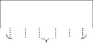
1.4 Function Key (Soft Key)
The Soft Key Functions are labeled on the bottom of display. Soft Key functions are different for each measurement.
V : 87°55'45"5
HR: 180°44'12"5
|
|
|
|
|
SD |
|
|
HD |
|
|
NEZ |
0SET HOLD |
|
|
P1↓ |
|
|
|
|||||||||||||
|
|
|
|
|
|
|
|
|
|
|
|
|
|
|
|
|
|
|
|
|
|
|
|
|
|
|
|
||||
|
|
|
|
|
|
|
|
|
|
|
|
|
|
|
|
|
|
|
|
|
|
|
|
|
|
|
|
||||
|
|
|
|
|
|
|
|
|
|
|
|
|
|
|
|
|
|
|
|
|
[F5] |
|
|
|
|
|
|
||||
|
|
|
|
|
[F1] |
|
[F2] |
|
[F3] |
[F4] |
|
|
|
[F6] |
|
|
|
|
|
||||||||||||
|
|
|
|
|
|
|
|
|
|
|
|
|
|
|
|
|
|
|
|
|
|
|
|
|
|
|
|
|
|
||
|
|
|
|
|
|
|
|
|
|
|
|
|
|
|
|
|
|
|
|
|
|
|
|
|
|
|
|
|
|
|
|
|
|
|
|
|
|
|
|
|
|
|
|
|
|
|
|
|
|
|
|
|
|
|
|
|
|
|
|
|
|
|
|
|
|
|
|
|
|
|
|
|
|
|
|
|
|
Soft keys |
|
|
|
|
|
|
|
|
|
|
|
|
|
||||
|
|
|
|
|
|
|
|
|
|
|
|
|
|
|
|
|
|
|
|
||||||||||||
V : |
87°55'45"5 |
|
|
|
|
|
|
|
|
|
|
|
|
|
V : |
90°10'20"5 |
|
|
|
||||||||||||
HR: 180°44'12"5 |
|
|
|
|
|
|
|
|
|
|
|
|
HR: 120°30'40"5 |
PSM |
0.0 |
|
|||||||||||||||
|
|
|
|
|
|
|
|
|
|
|
|
|
|
|
|
|
|
|
SD: |
|
|
|
|
|
|
|
PPM |
0.0 |
|
||
|
|
|
|
|
|
|
|
|
|
|
|
|
|
|
|
|
|
|
|
|
|
|
|
|
|
|
|
|
(m) |
F.R |
|
SD HD NEZ 0SET HOLD P1↓ |
|
|
|
|
|
MEAS MODE VH HD NEZ P1↓ |
|
||||||||||||||||||||||||
|
|
|
|
|
|
|
|
|
|
|
|
|
|
|
|
|
|
|
|
|
|
|
|
|
|
|
|
||||
|
TURN HSET R/L |
V/% TILT P2↓ |
|
|
|
|
|
|
TURN |
|
SO |
MEAN |
m/ft |
P2↓ |
|||||||||||||||||
|
|
|
|
|
|
|
|
|
|
|
|
|
|
|
|
|
|
|
|
|
|
|
|
|
|
|
|
||||
|
|
|
Angle measuring |
|
|
|
|
|
|
|
|
|
|
|
|
|
Slope distance measuring |
||||||||||||||
|
|
|
|
|
|
|
|
|
|
|
|
|
|
|
|
|
|
|
|
||||||||||||
V : |
90 10'20"5 |
|
|
|
|
|
|
|
|
|
|
|
|
|
N : |
12345.6789 |
|
|
|
||||||||||||
HR: 120 30'40"5 |
PSM |
0.0 |
|
|
|
|
|
|
E : -12345.6789 |
PSM |
0.0 |
|
|||||||||||||||||||
HD: |
|
|
|
|
|
PPM |
0.0 |
|
|
|
|
|
|
Z : |
|
10.1234 |
PPM |
0.0 |
|
||||||||||||
VD: |
|
|
|
|
|
|
(m) |
F.R |
|
|
|
|
|
|
|
|
|
|
|
|
|
|
|
(m) F.R |
|
||||||
MEAS |
MODE |
|
VH SD NEZ |
P1↓ |
|
|
|
|
|
MEAS MODE VH |
|
SD |
HD |
P1↓ |
|
||||||||||||||||
|
|
|
|
|
|
|
|
|
|
|
|
|
|
|
|
|
|
|
|
|
|
|
|
|
|
|
|
|
|
|
|
|
REC |
SO |
|
MEAN |
|
|
|
|
P2↓ |
|
|
|
|
|
|
TURN |
|
HT |
MEAN |
|
P2↓ |
||||||||||
|
|
|
|
|
|
|
|
|
|
|
|
|
|
|
|
|
|
|
|
|
|
|
|
|
|
|
|||||
|
|
Horizontal distance measuring |
|
|
|
|
|
|
Coordinate measuring |
|
|
||||||||||||||||||||
Page |
Display |
Soft |
Function |
|
key |
||||
|
|
|
||
|
|
|
|
|
|
SD |
F1 |
Slope distance measuring mode. |
|
|
|
|
|
|
Angle |
HD |
F2 |
Horizontal distance measuring mode. |
|
|
|
|
||
NEZ |
F3 |
Coordinate distance measuring mode. |
||
measuring |
||||
|
|
|
||
|
0SET |
F4 |
Set horizontal angle to 0°00'00". |
|
|
|
|
|
|
|
HOLD |
F5 |
Horizontal angle hold. |
|
|
|
|
|
|
|
TURN |
F1 |
Turns the instrument to required angle automatically. |
|
|
|
|
|
|
|
HSET |
F2 |
Preset a horizontal angle. |
|
|
|
|
|
|
|
R/L |
F3 |
Changes horizontal angle right or left. |
|
|
|
|
|
|
|
V/% |
F4 |
Changes the display to vertical angle or percent of grade. |
|
|
|
|
|
|
|
TILT |
F5 |
Sets the tilt function, ON/OFF. |
|
|
If ON, the display shows tilt correction value. |
|||
|
|
|
||
|
|
|
|
1-5
|
|
|
1 NOMENCLATURE AND FUNCTIONS |
|
|
|
|
|
|
Page |
Display |
Soft |
Function |
|
key |
|
|||
|
|
|
|
|
|
|
|
|
|
|
MEAS |
F1 |
Starts slope distance measurement mode. |
|
|
Changes Continuous/ N-times (single) measurement mode. |
|
||
|
|
|
|
|
|
|
|
|
|
Slope |
MODE |
F2 |
Changes Fine / Coarse(1mm) /Coarse(10mm) mode. |
|
|
|
|
|
|
VH |
F3 |
Angle measurement mode. |
|
|
distance |
|
|||
|
|
|
|
|
measuring |
HD |
F4 |
Horizontal distance measurement mode. Displays the horizontal distance |
|
|
data after N-times or single measurement. |
|
||
|
|
|
|
|
|
|
|
|
|
|
NEZ |
F5 |
Coordinate measurement mode. |
|
|
Displays the coordinate after N-times or single measurement. |
|
||
|
|
|
|
|
|
|
|
|
|
|
TURN |
F1 |
Turns the instrument to required angle automatically. |
|
|
|
|
|
|
|
SO |
F2 |
Stake out measurement mode. |
|
|
|
|
|
|
|
MEAN |
F3 |
Sets the number of N-time measurement. |
|
|
|
|
|
|
|
m/ft |
F4 |
Changes distance measurement unit to meter or feet. |
|
|
|
|
|
|
|
MEAS |
F1 |
Starts horizontal distance measurement mode. |
|
|
Changes continuous/ N-times (single) measurement mode. |
|
||
|
|
|
|
|
|
|
|
|
|
Horizontal |
MODE |
F2 |
Changes Fine / Coarse(1mm) /Coarse(10mm) mode. |
|
|
|
|
|
|
distance |
VH |
F3 |
Angle measurement mode. |
|
measuring |
|
|
|
|
SD |
F4 |
Slope distance measuring mode. |
|
|
|
|
|||
|
Display the slope distance after N-times or single measurement. |
|
||
|
|
|
|
|
|
|
|
|
|
|
NEZ |
F5 |
Coordinate measurement mode. |
|
|
Displays the coordinate after N-times or single measurement. |
|
||
|
|
|
|
|
|
|
|
|
|
|
TURN |
F1 |
Turns the instrument to required angle automatically. |
|
|
|
|
|
|
|
SO |
F2 |
Stake out measurement mode. |
|
|
|
|
|
|
|
MEAN |
F3 |
Sets the number of N-time measurement. |
|
|
|
|
|
|
|
m/ft |
F4 |
Switches meter or feet unit. |
|
|
|
|
|
|
|
MEAS |
F1 |
Starts coordinate measurement mode. |
|
|
Changes continuous/ N-times (single) measurement mode. |
|
||
|
|
|
|
|
|
|
|
|
|
Coordinate |
MODE |
F2 |
Changes Fine / Coarse(1mm) /Coarse(10mm) mode. |
|
|
|
|
|
|
VH |
F3 |
Angle measurement mode. |
|
|
measuring |
|
|||
|
|
|
|
|
|
SD |
F4 |
Slope distance measuring mode. |
|
|
Display the slope distance after N-times or single measurement. |
|
||
|
|
|
|
|
|
|
|
|
|
|
HD |
F5 |
Horizontal distance measurement mode. Displays the horizontal distance |
|
|
data after N-times or single measurement. |
|
||
|
|
|
|
|
|
|
|
|
|
|
TURN |
F1 |
Turns the instrument to required angle automatically. |
|
|
|
|
|
|
|
HT |
F2 |
Input Instrument / prism height values. |
|
|
|
|
|
|
|
MEAN |
F3 |
Sets the number of N-time measurement. |
|
|
|
|
|
|
|
m/ft |
F4 |
Switches meter or feet unit. |
|
|
|
|
|
|
|
SET |
F5 |
Pre-set instrument coordinate values. |
|
|
|
|
|
|
1-6
1 NOMENCLATURE AND FUNCTIONS
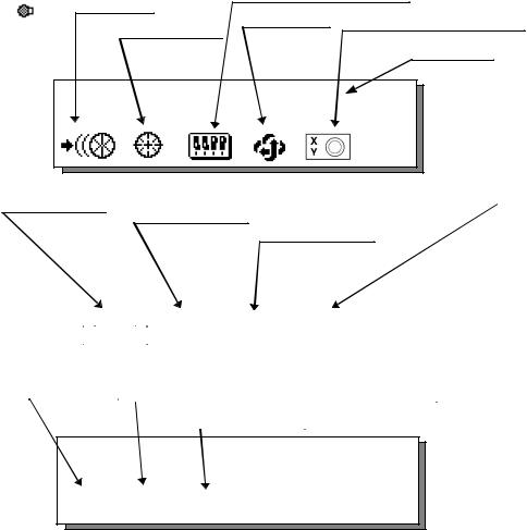
1.5 Star key (*key) mode
Press the (H) key to view the instrument options. Since there are three screens of options, press [F6](1↓) soft key to view the next screen.
The following instrument options can be selected from the (H):
•Screen One
1)View Date & Time
2)Auto-tracking [F1]
3)Auto-collimating [F2]
4)Set the parameters for Auto-tracking.[F3]
5)Autoinversion [F4]
6)Electric circular graphic display[F5]
•Screen Two
7)Adjustment the contrast of the display [F1 & F2]
8)Turn the back light of the display ON/OFF [F3]
9)Reticle illumination---Off / Low / Medium / High [F4]
10)View free memory for internal and card memory [F5]
• Screen Three
11)The light acceptance quantity level (signal level) is displayed.[F1]
12)Set the Temperature, Pressure, Atmospheric Correction Value (ppm), and Prism Constant Value (PSM) [F2]
13)Turn the Tracking Indicator option ON/OFF [F3]
Set parameter for Auto-tracking |
|
Auto-tracking |
|
Autoinversion |
Electric circular graphic display |
Auto-collimating |
|
|
Date & Time |
2003-10-10 14:30:40 |
|
|
Screen 1 |
|
1↓ |
View free memory for Card/Internal Memory Contrast adjustment 

Back Light of Display
Reticle illumination
|
|
|
|
|
|
2003-10-10 14:30:40 |
|
|
|
|
|||
|
|
|
|
|
|
|
|
|
|
||||
|
|
|
|
|
|
|
|
|
|
|
|
|
Screen 2 |
|
|
|
|
|
|
|
|
|
|
2↓ |
|
|
|
|
|
|
|
|
|
|
|
|
|
|
|
|
|
|
|
|
|
|
|
|
|
|
|
|
|
|
|
Displaying |
Set the Temperature, Pressure, Atmospheric Correction |
||||||||||||
Signal Level |
Value (PPM), and Prism Constant Value (PSM) |
||||||||||||
|
|
|
|
|
|
|
|
|
|
||||
|
|
|
|
|
|
|
|
|
|
|
|
|
|
|
|
|
|
|
|
|
|
Tracking indicator |
|||||
|
|
|
|
|
|
|
|
|
|
|
|
|
|
2003-10-10 14:30:40
Screen 3
3↓
1-7
1 NOMENCLATURE AND FUNCTIONS
1) View Date & Time
The date and time can be viewed on both screens.To change the displayed order of the date, (Date/ Month/Year), (Month / Date / Year) or (Year/Month/Date), see Chapter 8 “PARAMETERS SETTING MODE” .
To set the date and time, see Chapter 9 “CHECK AND ADJUSTMENT”.
2) Turn the auto-tracking ON/OFF
Press the [F1] key to start auto-tracking. See Section 3.1 “Automatic Tracking” .
3) Turn the auto-collimating ON/OFF
Press the [F2] key to start auto-collimating. See Section 3.2 “Automatic Collimation” .
4) Set the parameters for the auto-tracking
A proper setting for each parameter such as tracking pattern, tracking range, waiting time, tracking speed and tracking sensitivity. See Section 3.4 “Setting Parameters for Auto-Tracking” .
5) Auto Inversion
Pressing the [F4] key causes the instrument to reverse and turn the telescope and instrument automatically.
l To stop auto rotating in case of emergency, press any keys except POWER key.
lDuring auto rotation, do not disturb the instrument.(Stopping the rotation with a touch of the hand). Such action may cause trouble or harm to instrument or operator.
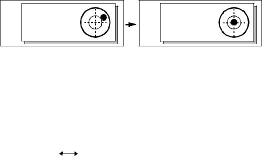
6) Electric circular level graphic display
Electric circular level can be displayed by graphic. This function is good for level the instrument when the circular level is difficult to see directly.
Press the [F5] key to display the graphic.
In the displays of reverse side, the graphic bubble moves in reverse.
X:------------- |
Y:------------- |
X:+0°00'00" |
Y:+0°00'00" |
Rotate the leveling screws while observing the display.
After leveling, press [F1]. The display changes to the previous mode.
7) Adjustment the contrast of the display
This enable you to adjust the contrast of the display. Press the [F6] key to get to Screen 2 on the display. Press the [F1] or [F2] key to brighten or dim the display.
8) Turn the display back light ON/OFF
When the back light is OFF, the light bulb icon is dark. Press the [F6] key to get to Screen 2 on the display.
To turn the back light ON, press the [F3] key. Press [F3] again to turn the back light OFF.
OFF |
ON |
1-8
1 NOMENCLATURE AND FUNCTIONS
9) Reticle illumination (OFF/Low/Middle/High)
Press the [F6] key to get to Screen 2 on the display. Press the [F4] key to turn the reticle illumination
ON. Continuing to press [F4] will change the intensity options.
|
OFF |
|
|
|
Middle |
|
|
|
|
|
Low |
|
|
High |
|||
10) View free memory
The amount of free memory for the card or internal memory can be displayed. Press the [F6] key to get to Screen 2 on the display.
Press the [F5] key to view free memory.
The card memory icon (top left side of the display) shows the size of the card and the amount of free memory. The second icon shows the amount of free internal memory.
Card Memory |
|
|
|
|
|
512KB |
315KByte |
|
|
|
|
||||||||
|
|
|
|
|
|
||||
Internal Memory |
|
|
|
|
|
|
|
1882KByte |
|
|
|
|
|
|
|
|
|
||
|
|
|
|
|
|
|
|
|
|
|
|
|
|
|
|
|
|
|
|
See Chapter 6 “MEMORY MANAGE MODES”, for further options and instructions.
11) Set audio mode
The light acceptance quantity level (Signal level) is displayed in this mode.
When reflected light from the prism is received, a buzzer sounds. This function is good for easy collimation when the target is difficult to find.
Press the [F1] key on screen 3.
The received return signal level is displayed with bar graph as follows.
|
|
|
|
|
|
|
|
|
|
|
|
|
|
|
|
|
|
|
|
|
|
|
|
|
|
|
|
|
|
|
|
|
|
|
|
|
|
|
|
No light acceptance |
|
|
Minimum quantity level |
|
Maximum quantity level |
||||||
(1)To stop the buzzer, see Chapter 8 “PARAMETERS SETTING MODE”.
(2)Also, it is possible to display the signal level in Distance Measuring Mode.
12)Setting Temperature, Pressure, Atmospheric correction value (ppm), Prism constant value (PSM)
The temperature, pressure, PPM, and PSM can be viewed by pressing the [F2] key on screen 3 . The received return signal level is displayed with bar graph as follows.
Refer to Chapter 10 “SETTING THE PRISM CONSTANT VALUE” and Chapter 11 “SETTING ATMOSPHERIC CORRECTION”, for further instructions.
1-9
1 NOMENCLATURE AND FUNCTIONS
13) Tracking Indicator
A man who is staying on line with the direction of GTS-820A series or automatic tracking status by emitted LED light (orange color) from GTS-820A series.
•Operation
Pressing [F3] key on screen three functions Tracking Indicator. The tracking indicator status will be changed according to the type of auto tracking mode and its conditions. A man from the prism side can recognize the status of instrument.
When angle measuring value turns stable during tracking still object, the tracking indicator changes from quick continuous flashing to quick intermittent flashing. So you can decide from the sign of flashing for recording data timing at one person surveying.
OFF |
ON |
Meaning of Tracking Indicator ON or Flashing
Tracking Indicator |
Tracking status of instrument |
|||
|
|
|
|
|
Continuous ON |
Wait status |
|||
|
|
|
|
|
Slow flashing |
Manual mode |
|||
|
|
|
|
|
Quick continuous flashing |
In case angle measuring value is instable during auto tracking |
|||
mode. |
||||
|
||||
|
|
|
|
|
Quick intermittent flashing |
In case angle measuring value is stable during auto tracking |
|||
mode. |
||||
|
||||
|
|
|
|
|
|
|
|
|
|
|
|
|
|
|
lThe function of the Tracking Indicator will be used as a guide to know the status of GTS-820A series from the prism side. This is not a function to determine precise collimating for measuring.
l The quality of its results will depend on the weather conditions and the use's eyesight.
lSometimes happens difficulty of seeing the tracking indicator because too much bright of the beam for tracking.
l Using Tracking Indicator mode will result shorter in reduced time out of the battery.
1-10
1 NOMENCLATURE AND FUNCTIONS
1.6 Auto Power Off
The Auto Power OFF feature can be set from 1 to 99 minutes. If no keys are pressed within the set time, the Auto Power OFF will automatically turn the instrument OFF in order to save the battery time. See Chapter 8 “PARAMETERS SETTING MODE”, for further instructions.
1.7 Data Output
When GTS-820A series receives data output command from an external connected device, the measured data will be output by GTS-820A series. Select from the following 2 ways for the output. (For setting, see Chapter 8 “PARAMETERS SETTING MODE” .)
REC-A : The measurement is started and new data is output.
REC-B : The data being displayed is output.
1.8 Rotating Method
1.8.1 Rotating by H/V Shuttle and H/V Jog
H/V shuttle or H/V jog can be used to rotate the instrument manually. The shuttle movement or displacement is proportional in speed and size of angle desired. A small, slow turn of the shuttle will result in a slow small angle displaced. Likewise, a larger abrupt turn of the shuttle will result in a coarse angle displacement. H/V jog can be used for accurate collimating of the target much like a standard tangent screw.
1.8.2 Auto Inversion
Pressing the [F4] key in Star Key mode causes the instrument to reverse and turn the telescope and instrument automatically.
lTo stop auto rotating by auto inversion key in case of emergency, press any keys except POWER key.
l During auto rotation, don't disturb the instrument.(Stopping the rotation with a touch of the hand). Such action may cause trouble or harm to instrument or operator.
See Section 1.5 “Star key (*key) mode” for further instructions.
1.8.3 Rotating automatically to a required Horizontal and Vertical angle
In Standard Measurement Modes, the instrument can be rotated automatically by input a required horizontal and/or vertical angle.
For further instructions, see Section 4.1.5 “Automatic Rotation to a Required Horizontal and Vertical Absolute Angle” .
V : |
87°55'45"5 |
This mark will appear while the |
instrument is rotating automatically. |
||
HR: |
180°44'12"5 |
|
SD HD NEZ 0SET HOLD P1↓
1-11
1 NOMENCLATURE AND FUNCTIONS
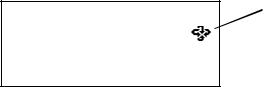
1.9 Using together with RC-2II Remote Control System
Using together with RC-2II Remote Control System makes it possible to optical communicate between the instrument and remote controller RC-2RII, the prism side. This gives easy operation by one man surveying in applying programs.
Also connecting data collector to remote controller, you can manage communication reciprocally between the instrument and direct to data collector.
Turn-round function
You can turn the GTS-820A series round to the remote controller RC-2RII side easily by [Turn-round] key of the remote controller RC-2RII. This function helps to increase one man surveying efficiency.
RC-2RII
See to Section 5.7 “External Link” and Chapter 8 “PARAMETERS SETTING MODE” for further information.
l Set the transmit path to " RC".
l Set the transmit channel same as RC-2RII side.
l To execute transmission, set the remote in Programs mode to [Remote].
1-12
1 NOMENCLATURE AND FUNCTIONS
1.10 Using connecting with Personal Computer (PC)
The auto-tracking function or auto collimating function makes easy remote control of the instrument from PC. The followings are the main communication commands and explanations. How to communicate or more informations of communication command, you can see the interface manual which provided optionally.
|
Commands |
Action of GTS-820A series |
|
|
|
|
|
|
Transmit command for measured data |
Each measured data will be out put |
|
|
according to the command type. |
||
|
|
||
|
|
|
|
|
Transmit command for tracking mode |
The status of Automatic Tracking mode |
|
|
will be out put. |
||
|
|
||
Transmit |
|
|
|
Transmit command for battery level |
The battery level will be out put. |
||
command |
|||
|
|
||
|
|
|
|
|
Transmit command for coordinate of |
Setting coordinate of instrument point will |
|
|
instrument point |
be out put. |
|
|
|
|
|
|
Transmit command for tracking |
Each setting tracking parameter of |
|
|
instrument will be out put according to the |
||
|
parameter |
||
|
command type. |
||
|
|
||
|
|
|
|
|
|
Each selecting mode in horizontal angle |
|
|
Setting of angle measurement |
or angle measurement can be decided |
|
|
|
according to the purpose of command. |
|
|
|
|
|
|
Setting of distance measurement |
Setting the measurement mode for |
|
|
distance measurement. |
||
Mode setting |
|
||
|
|
||
|
Setting coordinate of instrument point |
Setting the coordinate of instrument point. |
|
|
|
|
|
|
Setting the tracking parameter |
Setting each tracking parameter |
|
|
according to the command. |
||
|
|
||
|
|
|
|
|
T.I. ON / OFF |
ON / OFF of Tracking indicator. |
|
|
|
|
|
|
Rotating command |
Rotating of setting angle. |
|
|
|
|
|
Action |
Inversion |
Inversion movement. |
|
|
|
||
|
|
|
|
|
Setting tracking mode |
Setting from automatic tracking mode to |
|
|
each command mode. |
||
|
|
||
|
|
|
1-13

2 PREPARATION FOR MEASUREMENT
2 PREPARATION FOR MEASUREMENT
2.1 Power Connection
(unnecessary if on-board Ni-MH battery BT-56Q is used)
See below for connecting the external battery pack.
lBattery pack BT-3Q
Power cord , PC-5 is used.
lLarge capacity battery pack BT-3L
Power cord PC-6 is used.
lWhen using a external battery, the rechargeable battery BT-56Q should be attached (The instrument will lack in balance if the internal battery BT-56Q is removed.)
The external battery and the internal battery can be used at the same time. The GTS-820A series will select a battery due to the battery remaining automatically.
Connector ends
PC-5 |
BT-3Q |
PC-5 |
|
PC-6
BT-3L |
PC-6 |
PC-5 or PC-6
AC-6 External 12V Battery
2-1
2 PREPARATION FOR MEASUREMENT
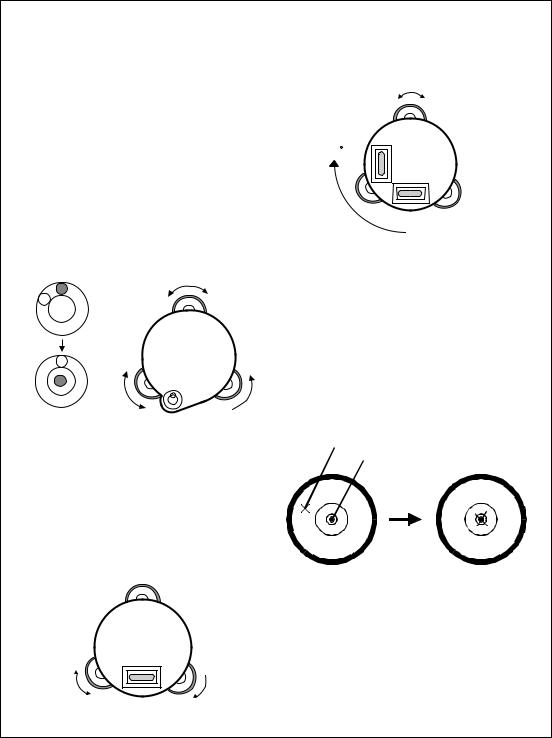
2.2 Setting Instrument Up For Measurement
Mount the instrument to the tripod. Level and center the instrument precisely to insure the best performance. Use tripods with a tripod screw of 5/8 in. diameter and 11 threads per inch, such as the Type E TOPCON wideframe wooden tripod.
Reference: Leveling and Centering the Instrument
1. Setting up the Tripod
First, extend the extension legs to suitable lengths and tighten the screws on their midsections.
2. Attaching the Instrument on the Tripod Head
Place the instrument carefully on the tripod head and slide the instrument by loosening the tripod screw. If the plumb bob is positioned right over the center of the point, slightly tighten the tripod screw.
3.Roughly Leveling the Instrument by Using the Circular Level
1Turn the leveling screws A and B to move the bubble in the circular level. The bubble is now located on a line perpendicular to a line running through the centers of the two leveling screws being adjusted.
Leveling screw C
Leveling  Leveling screw B
screw A
2 Turn the leveling screw C to bring the bubble to the center of the circular level.
4. Centering by Using the Plate Level
1Rotate the instrument horizontally by using the Horizontal motion/clamp screw and place the plate level parallel with the line connecting leveling screws A and B, and then bring the bubble to the center of the plate level by turning leveling screws A and B.
Leveling screw A
 Leveling
screw B
2Rotate the instrument 90° (100g) around its vertical axis and turn the remaining leveling screw or C to center the bubble once more.
Leveling screw C
90
3Repeat the procedures 1 and 2 for each 90° (100g) rotation of the instrument and check whether the bubble is correctly centered for all four points.
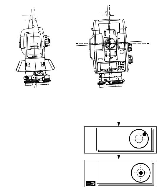
5.Centering by Using the Optical Plummet Telescope
Adjust the eyepiece of the optical plummet telescope to your eyesight.
Slide the instrument by loosening the tripod screw, place the point on the center mark, and then tighten the tripod screw. Sliding the instrument carefully not to rotate that allows you to get the least dislocation of the bubble.

 Point
Point

 Center mark
6. Completely Leveling the Instrument
Leveling the instrument precisely in a similar way to 4. Rotate the instrument and check to see that the bubble is in the center of the plate level regardless of telescope direction, then tighten the tripod screw hard.
2-2
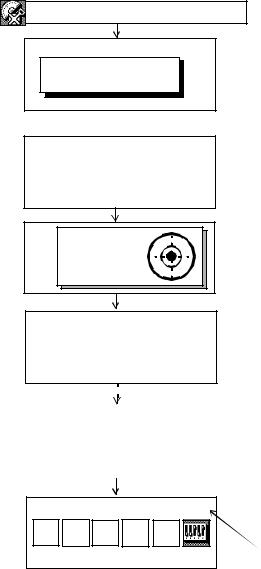
2.3 Power Switch Key ON
Power ON
Input a password |
|
[ |
] |
Self check mode
ESC
2 PREPARATION FOR MEASUREMENT
1)Confirm the instrument is leveled.
2)Turn the power switch ON.
3)Type your password.
Self checking mode will display.
To skip the self checking, press [F1](ESC) key.
X:+0°00'00" |
Y:+0°00'00" |
Self checking ...
[ 1/6 ]
Level the instrument by turning the leveling screws.
When the leveling is within ±30" and stable, the self checking will start.
|
Self checking ... |
|
The instrument will turn automatically and |
||
|
|
the tilt sensor offset value will be measured |
|||
|
|
|
|
|
|
|
|
[ 6/6 ] |
|
|
and memorized. |
|
|
|
|
|
|
|
|
|
|
|
|
2003-10-10 |
14:30 |
After checking, the main menu icons will be |
||
|
|
|
|
shown. |
Prog |
Std |
Mem |
Comm Adj |
Battery Power Remaining Display |
Para |
||||
|
Main menu icons |
|
||
l Self checking option
The self checking function is to check internal communication and tilt sensor offset value.
When ambient temperature is changed or the instrument is not balanced by its internal battery is
attached or detached, |
the self checking is recommended. |
l Password option |
|
Setting a password (Maximum 10 digits number) and activating ON of password option can be helpful to avoid miss operation by unauthorized operator.
Setting password option is necessary to use this function.
To set password option, see Chapter 8 “PARAMETERS SETTING MODE” . l Choosing the first mode when turning on the instrument
You can choose the first mode from the following modes when turning on the instrument. 1. Main Menu 2. Standard Measurement Mode 3. External Link
See Chapter 8 “PARAMETERS SETTING MODE” .
l ON/OFF of a self check function can also be chosen.
See Chapter 8 “PARAMETERS SETTING MODE” .
lConfirm the battery power remaining on the display. Replace with charged battery or charge when battery level is low. Refer to Section 2.4 “Battery Level Indicator” .
2-3
2 PREPARATION FOR MEASUREMENT
2.4 Battery Level Indicator
The battery power indicator shows the level of battery strength.
Indicates Battery Power Remaining
2003-10-10 15:30:40
Measurement is possible.
Prog Std Mem Comm Adj Para
|
|
The power is poor. The battery should be |
|
|
|
|
|
recharged or replace the battery. |
|
|
|
|
|
(Angle measurent can only be possible, |
|
|
the auto-collimating, auto-tracking and |
Blinking |
distance maesurenat can not be |
|
|
|
possible.) |
|
|
|
|
|
Measurement is impossible. Need to |
|
|
|
|
|
recharge or replace the battery. |
* Battery power remaining display is omitted in this manual.
Note:
1)The battery operating time will vary depending on the environmental conditions, such as ambient temperature, charging time, and the number of times charging and discharging the battery.
2)In low temperature (especially while the heater of display is working), the battery operating time will shorten to one-half of normal temperature use.
3)The indicator for battery power remaining shows the power level during each measurement mode. The condition indicated for the battery power remaining in the angle measurement mode may not be adequate to measure a distance. Changing from angle mode to distance mode during a poor battery condition may cause the EDM not to measure a distance.
We recommend that you check the battery condition before going into the field.
4)Also note, when changing from one measurement mode to another, the battery indicator may not show a decrease or an increase immediately. The battery indicator system was designed to show the general condition for the battery strength. It does not respond instantly.
5)For more information on battery usage, refer to Chapter 13 “POWER SOURCE AND CHARGING” .
2-4
2 PREPARATION FOR MEASUREMENT
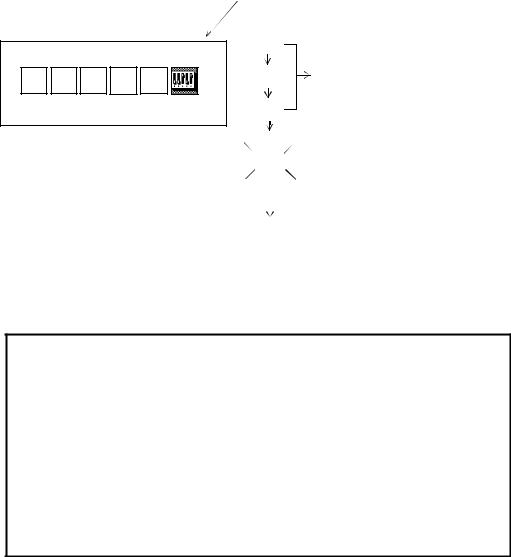
2.5 Main Menu Icons
The main menu icons are as follows.
Select the menu by pressing soft keys ([F1]~[F6]).
2003-07-10 15:30:40
Prog Std Mem Comm Adj Para

 PARAMETERS SETTING MODES
The PARAMETERS SETTING MODES are stored in memory once the instrument is OFF. (See Chapter 8 “PARAMETERS SETTING MODE”.)

 ADJUSTMENT MODES
Used for checking and adjustment.
l Systematic errors adjustment for compensation.
l Show compensation values of systematic errors of instrument
l Set Date & Time
l Set instrument constant value l Reference frequency of EDM l Optic Axis for Auto-tracking
(See Chapter 9 “CHECK AND ADJUSTMENT”.)
COMMUNICATION MODES
l Set communication with external instrument l Input/Output a data file
l Load application program.
(See Chapter 7 “COMMUNICATION MODES”.)

 MEMORY MANAGE MODES l Display memory status
l Protect/Eras/Rename/Copy Files, l Initialize a card or internal memory.
(See Chapter 6 “MEMORY MANAGE MODES” .)

 STANDARD MEASUREMENT MODES l Angle measurement
l Distance measurement
l Coordinate measurement
(See Chapter 4 “STANDARD MEASUREMENT MODE” .)
PROGRAM MODES ( APPLICATION MEASUREMENT) l Set a direction angle for horizontal orientation
l Retain Coordinate (STORE-NEZ) l Remote elevation measurement l Missing line measurement
l Line measurement l External link
l Off set measurement
(See Chapter 5 “PROGRAM MODES” .)
2-5
2 PREPARATION FOR MEASUREMENT
2.6 Vertical and Horizontal Angle Tilt Correction
When the tilt sensors are activated, automatic correction of vertical and horizontal angle for mislevelment is displayed.
To ensure a precise angle measurement, tilt sensors must be turned on. The display can also be used to fine level the instrument. If the (TILT OVER) display appears the instrument is out of automatic compensation range and must be leveled manually.
|
Zenith |
Zenith |
|
Standing axis |
Inclination of the standing |
Standing axis |
axis in the Y direction |
Inclination of the standing |
|
axis in the X direction |
|
Horizontal |
Trunnion axis |
|
V |
W |
X |
S |
T |
U |
P |
Q |
R |
O |
D |
| |
lGTS-820A series compensates both the vertical angle and the horizontal angle readings due to inclination of the standing axis in the X and Y directions.
lFor more information about dual axis compensation, see Chapter “APPENDIX” “Dual Axis Compensation”.
When the instrument tilted over correction range.
Rotate the leveling screws and level the instrument.
After leveling (when each axis is within ±1'30"), the display returns to the previous mode automatically.
X,Y tilt correction range : within ±4'
X: |
Y: |
X:+0°00'00" |
Y:+0°00'00" |
lThe display of Vertical or Horizontal angle is unstable when instrument is on an unstable stage or a windy day. You can turn off the auto tilt correction function of V/H angle in this case. To set TILT correction mode ON/OFF, refer to next page or Chapter 8 “PARAMETERS SETTING MODE”.
2-6
Loading...