


INSTRUCTION MANUAL
COMPUTERIZED TONOMETER
CT-80
INTRODUCTION
Thank you for purchasing the TOPCON Computerized Tonometer CT-80.
(To get the best use from the instrument, please carefully read these instructions and keep this Instruction Manual in a convenient location for future reference.)
This instrument features the following:
•An exact, non-contact intraocular pressure measurement that can be done by air ejection.
•An alignment bar that enables easy operation.
This text outlines the Computerized Tonometer CT-80 and describes basic operations, troubleshooting, checking, maintenance and cleaning.
To encourage the safe, efficient use of this instrument and prevent danger to the operator and others, we suggest you carefully read the “Displays for Safe Use” and the “Safety Cautions”.
Again, please keep this Instruction Manual in a convenient location for future reference.
Precautions
•This machine is a precision instrument; install it in a place set to the following conditions: temperature (10 60°C), humidity (30 85%) and atmospheric pressure (70 106KPa). Avoid direct exposure to sunlight.
•To ensure smooth operation, install the instrument on a level place free of vibrations. Also, do not place any objects on the instrument.
•Before using the instrument, connect all cables correctly.
•Use the specified source voltage.
•When not in use, turn the power off and put the measuring window cap and dust cover on.
•To ensure a correct reading, do not soil the measuring window with finger prints, dust, etc. Also, do not touch the measuring nozzle except when cleaning.
1

DISPLAY FOR SAFE USE
In order to encourage the safe use of the product and prevent any danger to the operator and others or damage to properties, important warnings are placed on the product and inserted in the instruction manual.
We suggest that everyone understand the meaning of the following displays and icons before reading the “Safety Cautions” and text.
DISPLAY
 WARNING
  CAUTION
MEANING
Ignoring or disregarding this display may lead to death or serious injury.
Ignoring or disregarding this display may lead to personal injury or physical damage.
•Injury refers to cuts, bruises, sprains, fractures, burn, electric shock, etc.
•Physical damage refers to extensive damage to buildings or equipment and furniture.
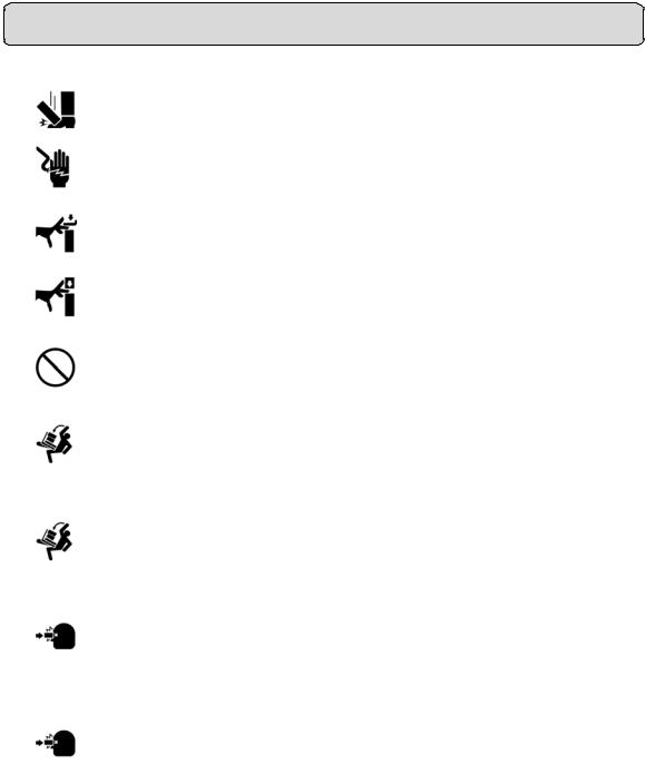
ICONS |
MEANING |
This icon indicates Hazard Alerting (Warning). Prohibition.
Specific content is expressed with words or an icon either inserted in the icon itself or located next to the icon.
This indicates Prohibition.
Specific content is expressed with words or an icon either inserted in the icon itself or located next to the icon.
This indicates Mandatory Action.
Specific content is expressed with words or an icon either inserted in the icon itself or located next to the icon.
2

SAFETY CAUTIONS
WARNING
Icons |
|
Prevention item |
Page |
||
|
|
|
To avoid electrical shock, do not open the instrument. |
45 |
|
|
|
|
|||
|
|
|
Refer all servicing to qualified personnel. |
||
|
|
|
|
|
|
|
|
|
|
|
|
|
|
|
To avoid electric shocks, do not remove the covers from the bottom |
45 |
|
|
|
|
|||
|
|
|
and top surfaces, TV monitor, measuring unit, etc. |
||
|
|
|
|
|
|
|
|
|
|
|
|
|
|
|
To prevent shock hazard, do not allow water or other foreign matter |
— |
|
|
|
|
|||
|
|
|
to enter into the instrument. |
||
|
|
|
|
||
|
|
|
|
|
|
|
|
|
|
|
|
|
|
|
To avoid fire and electric shocks in case of tumbling, do not place a |
— |
|
|
|
|
|||
|
|
|
cup or vessel containing water/fluid on the instrument. |
||
|
|
|
|
||
|
|
|
|
|
|
|
|
|
|
|
|
|
|
|
To avoid electric shocks, do not insert objects or metals through the |
— |
|
|
|
|
|||
|
|
|
vent holes or gaps or contain them inside the machine body. |
||
|
|
|
|
||
|
|
|
|
|
|
|
|
|
|
|
|
|
|
|
To avoid electrical shock and fire, unplug the power cable before |
55 |
|
|
|
||||
|
|
|
removing the fuse cover. Additionally, be sure to replace the fuse |
||
|
|
|
cover before plugging in the power cable. |
|
|
|
|
|
|
|
|
|
|
|
Use only the attached fuses. Using other fuses may cause a fire. |
55 |
|
|
|
|
|||
|
|
|
|
|
|
|
|
|
|
|
|
|
|
|
Should any anomaly, |
such as smoke, occur, immediately switch |
— |
|
|
|
OFF the power source and unplug the power cable. |
||
|
|
|
Continued use ignoring the condition may cause fire. Contact your |
|
|
|
|
|
dealer for repair. |
|
|
|
|
|
|
||
|
|
|
|
|
|
3
SAFETY CAUTIONS
CAUTION
|
Icon |
|
Prevention item |
Page |
|
|
|
|
|
|
|
|
To avoid potential injury, hold the instrument in the proper position. |
13 |
|
|
|
||
|
|
|
|
|
|
|
|
|
|
|
|
|
To avoid electrical shock, do not handle the power plug with wet |
14 |
|
|
|
||
|
|
|
fingers. |
|
|
|
|
|
|
|
|
|
|
|
|
|
|
|
|
|
|
|
Never insert your fingers under the measuring head. |
30 |
|
|
|||
|
|
|
Inform the patient of this, too. |
|
|
|
|
Careless insertion of fingers may cause injury by pinching. |
|
|
|
|
||
|
|
|
|
|
|
|
|
Never insert your fingers under the measuring head. |
34 |
|
|
|||
|
|
|
Inform the patient of this, too. |
|
|
|
|
Careless insertion of fingers may cause injury by pinching. |
|
|
|
|
||
|
|
|
|
|
|
|
|
Do not use or apply any spray-typed cleaner near the instrument. |
56 |
|
|
|||
|
|
|
If a drop of cleaner remains inside the measuring nozzle, the pa- |
|
|
|
|
tient’s eye may be injured during measurement. |
|
|
|
|
|
|
|
|
|
Before carrying the instrument, be sure to affix it firmly by turning |
|
|
|
|
the fixing screw at the base. |
13 |
|
|
|
If the instrument is moved with the screw loosened, it may result in |
|
|
|
|
damage to the instrument. |
|
|
|
|
||
|
|
|
|
|
|
|
|
When moving the instrument, be sure to hold it at the bottom sur- |
|
|
|
|
face with two people. Carrying by one person may cause back inju- |
13 |
|
|
|||
|
|
|
ry or injury by falling parts. Also, holding areas other than the bot- |
|
|
|
|
tom surface may cause pinching fingers between parts and injury |
|
|
|
|
by falling parts as well as damage to the instrument. |
|
|
|
|
|
|
|
|
|
Before measuring, set the safety stopper. If the safety stopper is |
|
|
|
|
not set, it may cause injury to the eye that comes in contact with the |
31 |
|
|
|
measuring window glass. Set the safety stopper separately for the |
|
|
|
|
|
|
|
|
|
right and left eyes. |
|
|
|
|
||
|
|
|
|
|
|
|
|
When setting the safety stopper, do it from the instrument side |
|
|
|
|
(safety stopper knob side). |
|
|
|
|
Setting from another position does not easily allow you to check the |
31 |
|
|
|
positions of the measuring window glass and the patient’s eye and |
|
|
|
|
may cause injury to the eye that comes in contact with the measur- |
|
|
|
|
||
|
|
|
ing window glass. |
|
|
|
|
|
|
|
|
|
To clean the measuring window glass and the window glass inside |
52 |
|
|
|||
|
|
|
the measuring nozzle, use ethanol. Using other chemicals may |
53 |
|
|
|
cause damage to the patient's eye during measurement. |
|
|
|
|||
|
|
|
|
|
4

USAGE AND MAINTENANCE
PURPOSE
This tonometer “CT-80” is a precision electrical device for medical use that must be used under the instruction of a doctor.
USER MAINTENANCE
To maintain the safety and performance of the equipment, never attempt to do maintenance on your own. Ask our serviceman for repair except for the items specified here which can be maintained by the user. For details, follow the instructions.
Fuse replacement
The primary fuses for the main body may be replaced by a non-trained service technician. For details, refer to “Replacing the Fuse” on page 55.
Cleaning of measuring window
Cleaning of the measuring window glass is possible. For details, refer to the instructions in “Cleaning the Measuring Window Glass” on page 52.
Cleaning of window inside the nozzle
Cleaning of the window inside the nozzle is possible by following the instruction in “Cleaning the Window Glass inside the Nozzle” on page 53.
ESCAPE CLAUSE
•TOPCON shall not take any responsibility for damage due to fire, earthquakes, actions by a third party or other accidents, or the negligence and misuse of the user and use under unusual conditions.
•TOPCON shall not take any responsibility for damage derived from the inability to use this equipment, such as a loss of business profit and suspension of business.
•TOPCON shall not take any responsibility for damage caused by operations other than those described in this Instruction Manual.
•Diagnoses shall be made on the responsibility of pertaining doctors and TOPCON shall not take any responsibility for the results of such diagnoses.
5
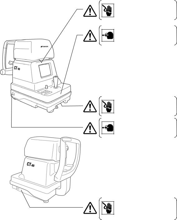
WARNING INDICATIONS AND POSITIONS
To ensure the safe usage of this equipment, precaution indications are provided.
Abide by the following warning instructions. If any of the following labels are missing, please contact us at the address printed on the back cover of this manual.
WARNING
• To avoid electrical shock, do not open the instrument. Refer all servicing to qualified personnel.
CAUTION
• To avoid potential injury during operation, do not touch the patient’s eyes or nose with the instrument.
WARNING
• To avoid electrical shock, do not open the instrument. Refer all servicing to qualified personnel.
CAUTION
• To avoid potential injury, insure that the safety stopper knob is engaged prior to use.
WARNING
• Electrical shock may cause burns or possible fire. Turn the main power OFF and UNPLUG the power cord before replacing the fuses. Replace only with fuses of the correct rating.
6

CONTENT
Introduction |
1 |
Display for Safe Use |
2 |
Safety Cautions |
3 |
Usage and Maintenance |
5 |
Escape Clause |
5 |
Warning Indications and Positions |
6 |
Main Body Components |
8 |
Control Panel Components |
9 |
Monitor Screen Components |
10 |
Contents of Printer Output |
11 |
Standard Accessories |
12 |
How to Install the Instrument |
13 |
How to Connect the Power Cable |
14 |
How to Connect External I/O Terminals |
14 |
Initial Settings |
15 |
How to Set Printer Paper |
23 |
How to Reset from Power Save Status |
28 |
Preparations Before Measurement |
29 |
Measurement Under Auto Mode |
33 |
Measurement Under Manual Mode |
38 |
How to Delete Measurement Values |
41 |
How to Print Out Measurement Values |
42 |
How to Correct Measurement Values |
43 |
Input/Output via RS-232C |
44 |
ICE |
|
Checking Operations |
45 |
Optional Accessories |
46 |
Specifications & Performance |
46 |
RS-232C Communication Specifications 47 |
|
Accuracy Maintenance |
52 |
Special Notes on Cleaning |
56 |
7

COMPONENTS
MAIN BODY COMPONENTS
Measuring head
Clamping knob
Safety stopper knob
Control panel
External I/O terminal
Power switch
Power cable
Adjusting knob
8
TV Monitor
Measuring switch
Control lever
Power lamp
Fixing knob (used to stop movements during removal)
Forehead rest Measuring window Measuring nozzle
 Height mark
Chinrest pad pin
Chinrest
Chinrest handle
Measuring window cap
COMPONENTS
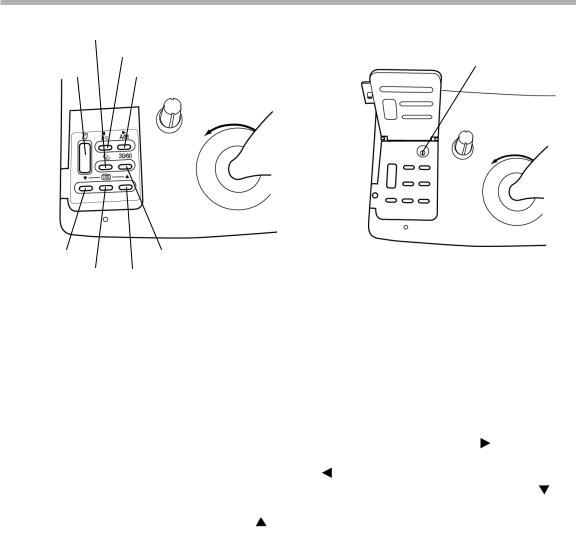
CONTROL PANEL COMPONENTS
Clear switch |
|
|
|
|
Air check switch |
Select switch |
|
Print switch |
Auto/Manual switch |
||
|
Down switch |
Range switch |
Menu switch |
Up switch |
Print switch ................... |
Prints out the screen readings. When there is no reading, holding |
|||
Range switch |
the switch down feeds the paper. |
|
|
|
Switches the range between 0-30 and 0-60. |
|
|
||
Clear switch .................. |
Deletes all the measurement values from the screen. |
|
||
Menu switch.................. |
Displays the Menu screen. |
|
|
|
Auto/Manual switch...... |
Switches the mode between auto and manual. |
Also, when se- |
||
Air check switch |
lecting menu software, it moves the cursor right ( |
). |
|
|
Performs an air check. |
Also, when selecting menu software, it |
|||
Down switch |
moves the cursor left ( |
). |
|
). |
When selecting menu software, it moves the cursor down ( |
||||
Up switch....................... |
Range switch. When |
selecting menu software, it moves |
the |
|
|
cursor up ( ). |
|
|
|
9
COMPONENTS
MONITOR SCREEN COMPONENTS
Measurement Screen (Auto mode, alignment)
Target eye
Measurement mode
Measuring range
Alignment dot
Measurement Screen (Manual mode, alignment OK)
Menu Screen
Cursor
10
Outer alignment mark Alignment bar
Inner alignment mark
Outer alignment mark
Inner alignment mark (alignment OK)
COMPONENTS
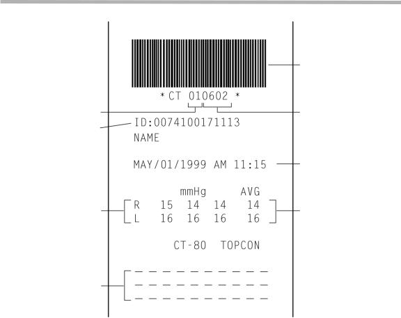
CONTENTS OF PRINTER OUTPUT
|
Bar code |
Equipment No. |
Work ID No. |
ID No. |
|
|
Time/Date display |
Measured eye pressure |
Average eye pressure |
values |
values |
Message column
11
COMPONENTS
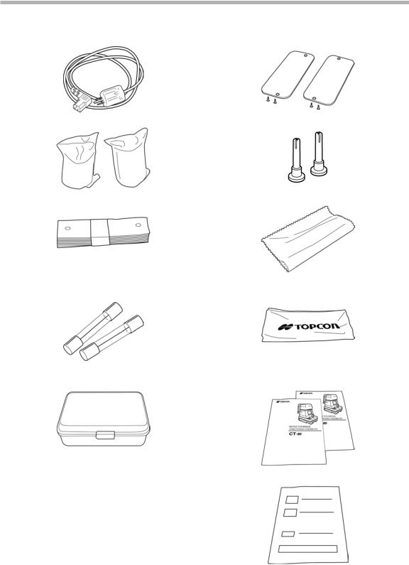
STANDARD ACCESSORIES
The following are the standard accessories. The figures in parentheses are the quantities. Please check to see that all accessories are contained.
Power cable (1) |
Rail cover (2) |
|
|
Printing paper (2) |
Chinrest pin (2) |
|
|
Chinrest pad (1) |
Silicone cloth (1) |
|
|
Fuse (2) |
Dust cover (1) |
* Different by destinations |
|
|
|
Cleaning kit (1) |
Instruction Manual, Unpacking and Assembly |
|
(1 each) |
|
|
|
Window glass cleaning procedure (1) |
|
|
12
COMPONENTS
PREPARATIONS
HOW TO INSTALL THE INSTRUMENT
 CAUTION
 CAUTION
 CAUTION
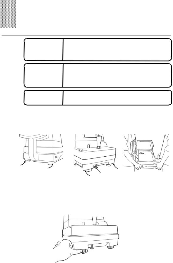
Before carrying the instrument, be sure to affix it firmly by turning the fixing screw at the base.
If the instrument is moved with the screw loosened, it may result in damage to the instrument.
When moving the instrument, be sure to hold it at the bottom surface with two people. Carrying by one person may cause back injury or injury by falling parts. Also, holding areas other than the bottom surface may cause pinching fingers between parts and injury by falling parts as well as damage to the instrument.
To avoid potential injury, hold the instrument in the proper position.
1 Fasten the clamping knob.
2 Hold the instrument body firmly at the specified positions and place it on the automatic instrument table.
For the automatic instrument table, see “OPTIONAL ACCESSORIES” on page 46.
Fixing knob |
|
Specified holding positions |
Holding the instrument |
3 After installing the instrument, loosen the fixing knob. |
|
Now the body components can be moved. |
|
4 If the machine body is slightly off level, properly turn the adjusters at the four corners for fine adjustment.
Do not unscrew the adjusters more than 1cm.
13
PREPARATIONS
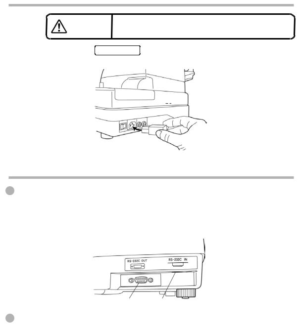
HOW TO CONNECT THE POWER CABLE
|
CAUTION |
To avoid electrical shock, do not handle the power plug |
|
with wet fingers. |
|
|
|
|
1 |
Make sure the POWER SWITCH is OFF. |
|
2 |
Attach the power cable to the machine body. |
|
3 Plug the power cable into the 3-pin AC receptacle with grounding.
HOW TO CONNECT EXTERNAL I/O TERMINALS
RS-232C OUT
This machine can be connected to another device, including a personal computer via the RS-232C OUT terminal.
1 Connect the cable to the RS-232C OUT terminal of this machine.
2 Connect the other cable end to another device.
RS-232C IN Output terminal Input terminal
This machine can be connected to another device, including a bar code reader via the RS-232C IN terminal.
1 Connect the cable to the RS-232C IN terminal of this machine.
2 Connect the other cable end to the external device.
14
PREPARATIONS
INITIAL SETTINGS
During the initial setting, date, time, operating time of the power save function, RS232C, mode of average value, buzzer and message can be set.
Preparations
1 Make sure the power cable is connected.
For connection, see “HOW TO CONNECT THE POWER CABLE” on page 14.
2 Check the no-patient condition of the instrument and turn the POWER SWITCH ON.
• |
When the machine is moved from a cold room to a warm room or |
MEMO |
when the room temperature suddenly rises, it may cause dewing in- |
side the machine and disable measurement. In this case, leave the |
|
|
machine alone for about 30min until it reaches room temperature. |
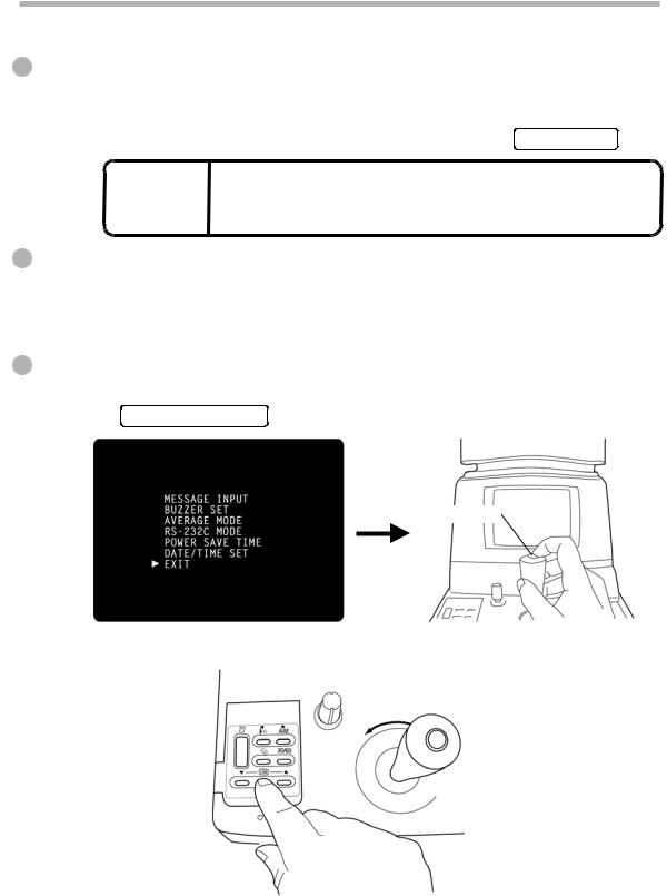
Displaying The Menu Screen
1 Make sure that the Measurement screen is displayed.
2 Press  on the control panel. The Menu screen is displayed.
Returning To The Measurement Screen
1 Press  ,
,  on the control panel, move the cursor to “EXIT” and press
MEASUREMENT SWITCH .
Measurement switch
Or, press  on the control panel. The Measurement screen returns.
15
PREPARATIONS
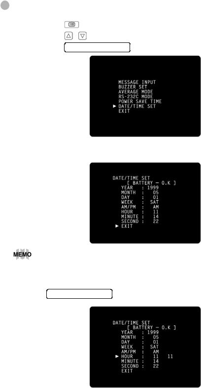
Time/Date Setting
Example of operation: Illustrations show time setting.
1 |
Press |
|
on the control panel to get the Menu screen. |
2 |
Press |
, |
on the control panel, move the cursor to “DATE/TIME SET” and |
|
press |
MEASUREMENT SWITCH . |
|
The Date/Time setting screen is displayed.
3 Make sure that the display “BATTERY → O.K.” appears.
If the display is “BATTERY → N.G.”, the built-in clock battery is used up. Contact your dealer. Additionally, when the battery becomes exhausted, time and date items are not printed and “DATE” is displayed instead.
4 Press  ,
,  on the control panel, move the cursor to “HOUR” and press
MEASUREMENT SWITCH .
16
PREPARATIONS

5 Press  ,
,  of the control panel, renew figures and press MEASUREMENT SWITCH . The renewed figures are inputted.
6 Press  ,
,  of the control panel, move the cursor to “EXIT” and press
MEASUREMENT SWITCH .
Date and other items can also be renewed at the same time.
Setting The Power Save Time
A time for the power save function to achvale can be selected from 10, 20, 30 or 60min. For shipment, 10min. is set.
1 |
Return to the Menu screen. |
||
2 |
Press |
, |
on the control panel, move the cursor to “POWER SAVE TIME” and |
|
press |
MEASUREMENT SWITCH . The Power Save Time Setting screen is displayed. |
|
3 Press  ,
,  on the control panel and change the power save time.
17
PREPARATIONS
 Loading...