


THERMADOR PROFESSIONAL® PRO GRAND® DUAL FUEL RANGES

THERMADOR PROFESSIONAL® PRO GRAND® Dual Fuel Ranges
Cuisinières Mixtes PROFESSIONAL PRO GRANDmc de THERMADOR
Estufas Mixtas PROFESSIONAL PRO GRAND® de THERMADOR
Table of Contents............................................................................... |
2 |
Table de Matières ............................................................................ |
29 |
Índice de Materias ........................................................................... |
57 |
Models | Modèles | Modelos
PRD364JDGC
PRD364JDGU
PRD366JGC
PRD366JGU
PRD486JDGC
PRD486JDGU
PRD48JDSGC
PRD48JDSGU
PRD364NLGC
PRD364NLGU
PRD484NCGC
PRD484NCGU
PRD486NLGC
PRD486NLGU
PRD48NCSGC
PRD48NCSGU
PRD48NLSGC
PRD48NLSGU
Table of Contents |
|
Safety Instructions ....................................................................................................................................................... |
3 |
Before You Begin...................................................................................................................................................... |
3 |
Installation ..................................................................................................................................................................... |
5 |
Planning Information ................................................................................................................................................. |
5 |
STEP 1: Ventilation Requirements ........................................................................................................................... |
5 |
STEP 2: Cabinet Preparation ................................................................................................................................... |
6 |
STEP 3: Unpacking & Moving the Range .............................................................................................................. |
12 |
STEP 4: Door Removal & Adjustment .................................................................................................................... |
13 |
STEP 5: Installing Anti-Tip Device ......................................................................................................................... |
15 |
STEP 6: Gas Requirements and Hookup ............................................................................................................... |
16 |
STEP 7: Electrical Requirements, Connection & Grounding .................................................................................. |
18 |
STEP 8: Backguard Installation (optional) .............................................................................................................. |
20 |
STEP 9: Placing and Leveling the Range .............................................................................................................. |
24 |
STEP 10: Burner Test ............................................................................................................................................. |
26 |
Installer Final Check List ........................................................................................................................................... |
28 |
Customer Support, Accessories & Parts ..................................................................................................... |
back page |
Safety Definitions |
|
WARNING |
|
This indicates that death or serious injuries may occur as |
|
a result of non-observance of this warning. |
|
CAUTION |
|
This indicates that minor or moderate injuries may occur |
|
as a result of non-observance of this warning. |
|
NOTICE: This indicates that damage to the appliance or property may occur as a result of non-compliance with this advisory.
Note: This alerts you to important information and/or tips.
This THERMADOR® appliance is made by BSH Home Appliances Corporation 1901 Main Street, Suite 600
Irvine, CA 92614
Questions?
1-800-735-4328 www.thermador.com
We look forward to hearing from you!
Table of Contents |
English 2 |
Safety
IMPORTANT SAFETY INSTRUCTIONS
READ AND SAVE THESE INSTRUCTIONS
Before You Begin
IMPORTANT: Save these instructions for the Local Gas Inspector’s use.
INSTALLER: Please leave these Installation Instructions with this unit for the owner.
OWNER: Please retain these instructions for future reference.
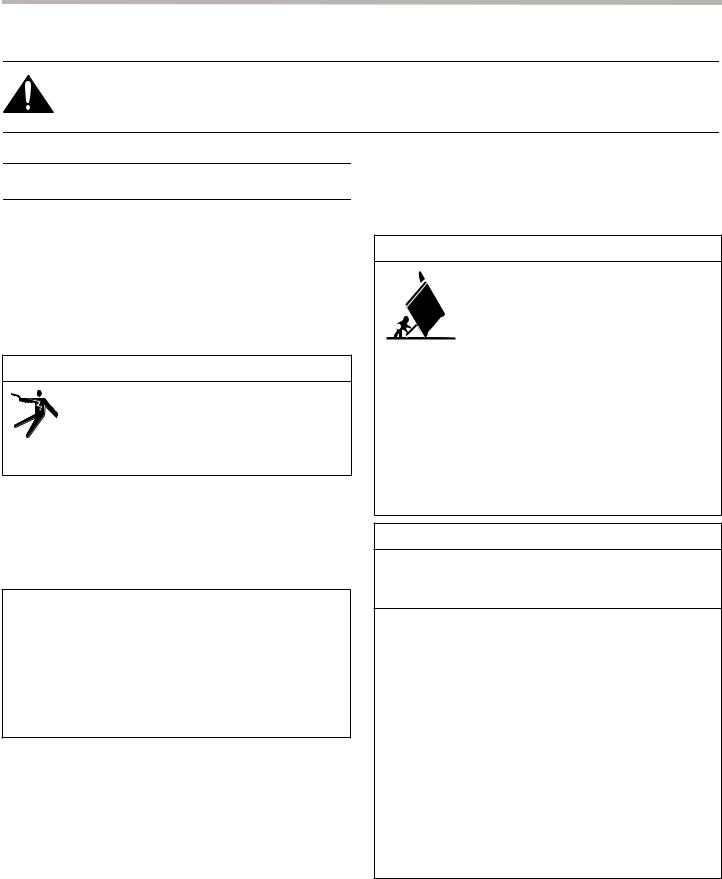
WARNING
ELECTRICAL SHOCK HAZARD
Disconnect power before installing or servicing. Before turning power ON, be sure that all controls are in the OFF position. Failure to do so can result in death or electrical shock.
IMPORTANT:
Local codes vary. Installer is responsible for ensuring that the installation, gas connections, and grounding comply with all applicable codes. Failure to follow appropriate local codes and regulations may void the warranty.
For Massachusetts Installations:
1.Installation must be performed by a qualified or licensed contractor, plumber or gas fitter qualified or licensed by the state, province or region where this appliance is being installed.
2.Shut-off valve must be a “T” handle gas cock.
3.Flexible gas connector must not be longer than 36” (914 mm).
GROUNDING INSTRUCTIONS
This appliance must be grounded. Grounding reduces the risk of electric shock by providing a safe pathway for electric current in the event of a short circuit.
Examine the appliance after unpacking it. In the event of transport damage, do not plug it in.
Remove all tape and packaging before using the appliance. Destroy the packaging after install. Never allow children to play with packaging material.
NOTE: This range is NOT designed for installation in manufactured (mobile) homes or recreational park trailers.
DO NOT install this range outdoors.
WARNING
A child or adult can tip the range over and be killed or seriously injured. Verify that the anti-tip bracket is securely installed. Ensure the anti-tip bracket is engaged when the range is moved.
DO NOT operate the range without the anti-tip bracket in place. Failure to follow the instructions in this manual can result in death or serious burns to children and adults.
Check for proper installation and use of anti-tip bracket. Carefully tip range forward pulling from the back to ensure that the anti-tip bracket engages the range aluminum cast base and prevents tip-over. Range should not move more than 1 inch (2.5 cm).
WARNING
If the information in this manual is not followed exactly, a fire or explosion may result causing property damage, personal injury or death.
—DO NOT store or use gasoline or other flammable vapors and liquids in the vicinity of this or any other appliance.
—WHAT TO DO IF YOU SMELL GAS
•DO NOT try to light any appliance.
•DO NOT touch any electrical switch.
•DO NOT use any phone in your building.
•Immediately call your gas supplier from a neighbor’s phone. Follow the gas supplier’s instructions.
•If you cannot reach your gas supplier, call the fire department.
—Installation and service must be performed by a qualified installer, service agency or the gas supplier.
Installation Instructions |
English 3 |
IMPORTANT SAFETY INSTRUCTIONS
READ AND SAVE THESE INSTRUCTIONS
Gas Type Verification
Verify that the appliance is correct for the type of gas provided at installation location. Ensure that the appliance is connected to the type of gas for which it is certified. Before proceeding with the installation refer to “STEP 6: Gas Requirements and Hookup” on page 16 for specifications.
All models are certified for use with natural gas. Field conversion of the appliance for use with propane gas supply will require installation of conversion kit, supplied with the range (service number 00553182). Only a qualified service technician or installer should make this conversion. See LP Conversion Kit Instruction for full installation information.
Gas Supply
Natural Gas – 6'' water column (14.9 mb) min., 14'' (34.9 mb) maximum
Propane Gas – 11'' water column (27.4 mb) min., 14'' (34.9 mb) maximum
WARNING
State of California Proposition 65 Warnings:
This product contains chemicals known to the State of California to cause cancer, birth defects or other reproductive harm.
Electric Power Supply
See “STEP 7: Electrical Requirements, Connection & Grounding” on page 18 for specifications.
Check local building codes for the proper method of appliance installation. Installation, electrical connections and grounding must comply with all applicable codes. Local codes vary and it is the responsibility of the installer to ensure installation is in accordance with these codes. In the absence of local codes the appliance should be installed in accordance with the National Fuel Gas Code ANSI Z223.1/ NFPA 54 current issue and National Electrical Code ANSI/ NFPA 70-current issue. In Canada, installation must be in accordance with the CAN 1-B149.1 and .2 – Installation Codes for Gas Burning Appliances and/or local codes.
Safety Codes and Standards
This appliance complies with the following standards:
•UL 858, Standard for the Safety of Household Electric Ranges
•ANSI Z21.1, American National Standard for Household Cooking Gas Appliances
•CAN 1-1. 1-M81, Domestic Gas Ranges
•CAN/CSA-C22.2 No. 61, Household Cooking Ranges
It is the responsibility of the owner and the installer to determine if additional requirements and/or standards apply to specific installations.
IMPORTANT:
When installing against a combustible surface, a Low Backguard is required. A THERMADORTM Low Backguard must be purchased separately. See “STEP 8: Backguard Installation (optional)” on page 20 for backguard and installation information.
When using the Flush Island Trim, THERMADOR recommends a minimum 12'' (305 mm) rear clearance to a combustible surface (see “Installation Clearances” on page 7). Clearances from non-combustible materials are not part of the ANSI Z21.1 scope and are not certified by CSA. Clearances of less than 12'' (305 mm) must be approved by the local codes and/or by the local authority having jurisdiction.
Refer to Table 3, “Backguard Kit Model Numbers,” on page 20, for the correct backguard models that are designed for this range. After selecting the correct backguard, the range must be installed properly, using the minimum clearances to combustible surfaces specified in
“STEP 2: Cabinet Preparation” on page 6.
WARNING
To avoid possible burn or fire hazard, a backguard designed specifically for this range must be installed whenever the range is used.
CAUTION
To eliminate risk of burns or fire caused by reaching over heated surface units, cabinet storage located above the surface units should be avoided.
Installation Instructions |
English 4 |
Installation
Planning Information
Before using your appliance, be sure to read this manual. Pay special attention to the Important Safety Instructions located at the beginning of the manual.
TOOLS NEEDED
(2) 1/2'' wrenches |
1/8'' (3.17 mm) drill bit |
|
|
3/16'' (4.76 mm) drill bit |
12'' adjustable wrench |
|
|
Hand or electric drill |
Tape measure |
|
|
Phillips & flathead screwdrivers |
Marking instrument |
|
|
Level |
Furniture dolly |
|
|
T-20 Torx screwdriver |
Protective gloves |
|
|
ITEMS NOT INCLUDED |
|
|
|
Drywall/Concrete Anchors |
Pipe Compound/Tape |
|
|
Rope/Twine |
¾'' (19 mm) Flex Line |
|
|
Strain Relief |
|
|
|
STEP 1: Ventilation
Requirements
Refer to the Ventilation Planning Guide for approved ventilation combinations.
It is strongly recommended that this appliance be installed in conjunction with a Thermador vent hood. Due to the high heat capability of this unit, particular attention should be paid to the hood and duct work installation to assure it meets local building codes.
Downdraft ventilation should not be used. The Ventilation Planning Guide indicates the ventilation hood options and blower capacity guidelines that are recommended for use with all Thermador ranges.
Due to the high heat of the rangetop burners, do not install a microwave oven/ventilator combination above the range, as these types of units do not provide the proper ventilation and are not suitable for use with the range.
IMPORTANT:
Ventilation hoods and blowers are designed for use with single wall ducting. However, some local building codes or inspectors may require double wall ducting. Consult local building codes and/or local agencies before starting to assure that hood and duct installation will meet local requirements.
NOTICE: Most range hoods contain combustible components which must be considered when planning the installation.
WARNING
This appliance should not be installed with a ventilation system that directs air in a downward direction toward the range. This type of ventilation system may cause ignition and combustion problems with the appliance resulting in personal injury, property damage, or unintended operation. Ventilating systems that direct the air upwards do not have any restriction.
Ventilation Preparation
1.Select Hood and Blower Models
•For wall installations, the hood width must, at a minimum, equal the width of the range. Where space permits, a hood larger in width than the range may be desirable for improved ventilation performance.
•For island installations, the hood width should overhang the range by a minimum of 3" (76 mm) on each side.
2.Hood Placement
•For best smoke elimination, the lower edge of the hood should be installed 30" (762 mm) above the range cooking surface.
•If the hood contains any combustible materials (i.e. a wood covering), it must be installed a minimum of 36" (914 mm) above the cooking surface (See “Installation Clearances” beginning on page 7.).
3.Consider Make-Up Air
•Due to the high volume of ventilation air, a source of outside replacement air is recommended. This is particularly important for tightly sealed and insulated homes. A qualified heating and ventilating contractor should be consulted.
Installation Instructions |
English 5 |

STEP 2: Cabinet Preparation
•The range is a free standing unit. If the unit is to be placed adjacent to cabinets, the clearances shown in
“Installation Clearances” on page 7 are required. The same clearances apply to island installations, except for the overhead cabinets, which must have a space wide enough to accept the flared island hood.
•The range should not be recessed into the cabinets beyond the edge of the front face of the oven (see clearances beginning on page 8).
•The gas and electrical supply should be within the zones shown in Figure 5 on page 11.
•Any openings in the wall behind the range and in the floor under the range must be sealed.
•When installing against a combustible surface, a Low Backguard is required. A THERMADOR Low Backguard must be purchased separately (see
Table 3, “Backguard Kit Model Numbers,” on page 20).
•When using the Flush Island Trim, THERMADOR recommends a minimum 12'' (305 mm) rear clearance to a combustible surface (see Figure 4, Installation Clearances with Flush Island Trim). Clearances from non-combustible materials are not part of the ANSI Z21.1 scope and are not certified by CSA. Clearances of less than 12'' (305 mm) must be approved by the local codes and/or by the local authority having jurisdiction.
•When the range is installed against a combustible side wall a minimum clearance of 5'' (127 mm) is needed from the side of the range to the wall. (See “Installation Clearances” beginning on page 7.)
•Always keep appliance area clear from combustible materials, gasoline and other flammable vapors and liquids.
•The maximum depth of overhead cabinets installed on either side of the hood is 13" (330 mm). Wall cabinets must be 18'' (457 mm) above the countertop (See “Installation Clearances” beginning on page 7.)
•Do not obstruct the flow of combustion and ventilation air to the unit.
•There is a 36'' (914 mm) minimum clearance required between the top of the cooking surface and the bottom of an unprotected cabinet. A 30'' (762 mm) clearance can be used when the bottom of the wood or metal cabinet is protected by not less than 1/4'' (6 mm) of a flame retardant material covered with not less than No. 28 MSG sheet steel, 0.015'' (0.38 mm) thick stainless steel, 0.024'' (0.61 mm) aluminum, or 0.02'' (0.51 mm) thick copper. (See “Installation Clearances” beginning on page 7.)
Flame retardant materials bear the mark: UNDERWRITERS LABORATORIES INC. CLASSIFIED MINERAL AND FIBER BOARDS SURFACE BURNING CHARACTERISTICS, followed by the flame spread and smoke ratings. These designations are shown as “FHC (FIame Spread/Smoke Developed).” Materials with “O” flame spread ratings are flame retardant. Local codes may allow other flame spread ratings. It is the responsibility of the installer to ensure installation is in accordance with these ratings.
Installation Instructions |
English 6 |
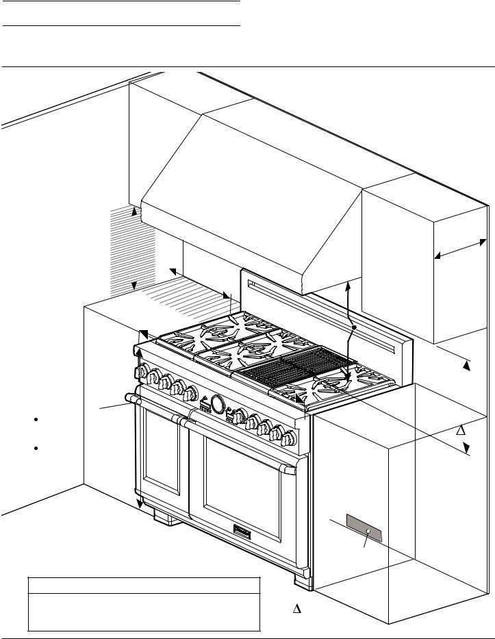
Installation Clearances
Installation Clearances with Low Backguard
See |
the |
|
|
|
|
|
|
for |
|
Ventilation |
|
|
|
||
|
|
|
Planning |
|
|||
|
recommended |
|
Guide |
||||
|
|
|
|
hood |
|
||
|
|
|
|
|
|
options. |
|
|
|
|
|
|
|
|
|
|
|
|
|
|
|
|
|
|
|
|
|
13" |
mm) |
|
|
|
|
|
|
|
|
|
|
|
|
|
|
|
|
|
|
|
|
(330 |
|
|
|
|
|
|
|
|
|
|
|
|
|
|
|
|
|
|
|
|
|
|
|
|
|
mm) |
|
|
|
|
|
|
|
|
|
|
|
|
|
|
|
|
|
. |
|
|
|
|
|
|
|
|
|
|
|
|
|
|
|
|
|
|
|
|
max |
|
|
|
" |
(457 |
|
|
|
|
|
|
|
|
|
|
|
|
|
|
|
|
|
|
|
18 |
5 |
|
|
|
|
|
|
|
|
|
|
|
|
|
|
|
|
cabinet |
|||
|
|
|
|
|
|
|
|
|
|
|
|
|
|
|
|
|
|||||
minimum |
|
|
|
|
|
|
|
|
|
|
|
|
|
|
|
|
|
|
|||
" |
(127 |
|
|
|
|
|
|
|
|
|
|
|
|
|
|
|
depth |
|
|||
|
|
|
to |
mm) |
|
|
|
|
|
|
|
|
|
|
|
|
|
|
|
||
|
|
|
|
|
|
|
|
|
|
|
|
|
|
|
|
|
. |
|
|||
|
|
|
|
|
min. |
|
|
|
|
|
|
|
|
mm) |
min |
|
|||||
|
|
|
|
|
|
|
|
|
|
|
|
|
|
|
|
|
|||||
|
|
|
|
combustible |
|
|
|
|
(762 |
|
|
of |
|
|
|||||||
|
|
|
sidewalls |
|
|
|
30" |
|
bottom |
|
. |
|
|||||||||
|
|
|
|
|
|
|
|
|
from |
|
|
|
|
hood |
|
|
|||||
|
|
|
|
|
|
|
|
|
|
|
|
|
|
surface |
|
||||||
|
|
|
|
|
|
|
|
|
overhead |
|
|
|
. |
|
|||||||
|
|
|
|
|
|
|
|
|
|
|
cooking |
|
|
|
|||||||
|
|
|
|
|
|
|
|
|
to |
min |
|
||||||||||
|
|
|
|
|
|
|
|
|
|
|
(914 |
mm) |
|
. |
|
||||||
|
|
|
|
|
|
|
|
|
|
|
|
|
|
|
|
|
|||||
|
|
|
|
|
|
|
|
|
|
|
|
|
|
|
|
|
|
||||
|
|
|
|
|
|
|
|
|
36" |
|
|
contains |
|
|
|||||||
|
|
|
36" |
|
|
|
|
|
|
|
|
|
|
|
material |
|
|||||
|
|
|
|
|
|
|
|
if |
hood |
|
|
|
|
|
|
|
|
||||
|
|
|
|
|
|
|
|
|
|
|
|
|
|
|
|
|
|
|
|
||
|
|
|
or |
48" |
(914 |
|
|
combustible |
|
|
|
||||||||||
|
|
|
|
|
|
|
|
|
|||||||||||||
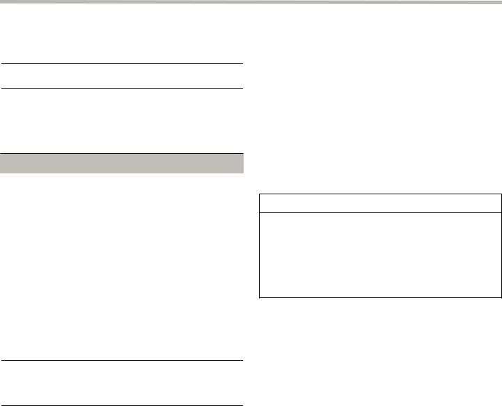
The range height is adjustable. |
|
or |
|
|
|
|
|
|
|
|
|
|
|
|
|
|
|||||
|
|
1219 |
|
|
|
|
|
|
|
|
|
|
|
|
|
||||||
|
|
|
|
|
|
|
|
|
|
|
|
|
|
|
|
|
|||||
The level of the range top must |
|
|
|
|
|
mm) |
|
|
|
|
|
|
|
|
|
|
m CAUTION! |
|
|||
be at the same level or above |
|
|
|
|
|
|
|
|
|
|
|
|
|
|
|
|
36" (914 mm) min. |
||||
the counter top level. |
|
|
|
|
|
|
|
|
|
|
|
|
|
|
|
|
|
|
|
to combustible |
|
35⅞" (911 mm) Min. range |
|
|
|
|
|
|
|
|
|
|
|
|
|
|
|
|
|
material |
|
||
|
|
|
|
|
|
|
|
|
|
|
|
|
|
|
|
|
from Cooking |
||||
height with leveling legs fully |
|
|
|
|
|
|
|
|
|
|
|
|
|
|
|
|
|
Surface |
|
||
retracted. |
|
|
|
|
|
|
|
|
|
|
|
|
|
|
|
|
|
|
|
|
|
36¾" (933 mm) Max. range |
|
|
|
|
|
|
|
|
|
|
|
|
|
|
|
|
|
|
|
||
height with leveling legs fully |
|
|
|
|
|
|
|
|
|
|
|
|
|
|
|
|
|
|
|
||
extended. |
|
|
|
|
|
|
|
|
|
|
|
|
|
|
|
|
|
|
|
|
|
For Gas Supply & Electrical Zones
see Figure 5.
9CAUTION
Do not install the range such that the oven door is flush |
as defined in the “National Fuel Gas Code” (ANSI Z223.1, Current Edition). |
with the cabinet face. A flush installation could result in |
|
damage to the cabinets due to exposure to high heat. |
Clearances from non-combustible materials are not part of the ANSI Z21.1 |
scope and are not certified by CSA. |
Figure 1: Cabinet Clearances with Low Backguard
Installation Instructions |
English 7 |
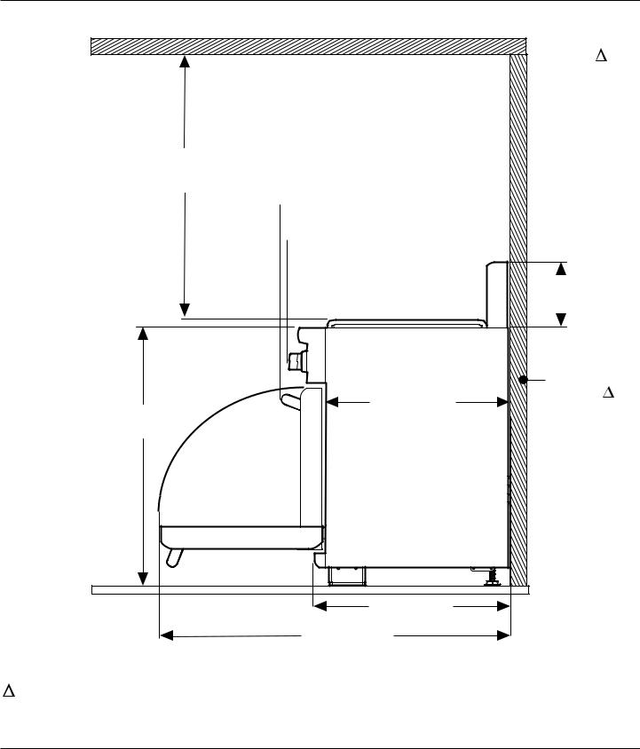
Installation Clearances with Low Backguard
 Combustible
Materials
36" (914 mm) min. to combustible materials 
 31¼" (794 mm)
 29⅛" (740 mm)
9" (229 mm) Lowback
|
|
Combustible |
|
25⅛" (638 mm) |
Back Wall |
35⅞" (911 mm) Min. |
|
|
max. recess depth |
|
|
36¾" (933 mm) Max. |
|
|
|
26⅞" (683 mm) |
|
|
48¾" (1238 mm) |
|
As defined in the “National Fuel Gas Code” (ANSI Z223.1, Current Edition).
Clearances from non-combustible materials are not part of the ANSI Z21.1 scope and are not certified by CSA. Clearances of less than 12" (305 mm)
must be approved by the local codes and/or by the local authority having jurisdiction.
Figure 2: Installation Clearances with Low Backguard
Installation Instructions |
English 8 |
 Loading...