


Thermador SEC271, SEC272, SECD272, SEC301, SEC302 Installation Instructions
...INSTALLATION
INSTRUCTIONS
B u i l t-i n E l e c t r i c C o n v e c t i o n O v e n s
Models:
SEC271
SEC272
SECD272
SEC301
SEC302
SECD302
SEM272
SEMW272
SEM302
SEMW302
C271
C272
C301
C302
CM301
CM302
Please read this entire instruction manual before proceeding.
IMPORTANT: Local codes vary. Installation, electrical connections, circuit breakers and grounding must comply with all applicable codes. Save these instructions for the Local Electrical Inspector's use.
INSTALLER: Please leave these Installation Instructions with this unit for the owner.
OWNER: Please retain these instructions for future reference.
 WARNING
Disconnect power at the breaker before installing.
TABLE OF CONTENTS |
|
STEP 1: UNPACKING ........................................................ |
3 |
STEP 2: CABINET PREPARATION ................................. |
4 - 7 |
STEP 3: ELECTRICAL INSTALLATION ................................. |
8 |
208-VOLT ELECTRICAL HOOKUP .......................... |
8 |
STEP 4: INSTALLING THE OVEN ....................................... |
9 |
REMOVING THE OVEN DOOR .............................. |
9 |
REPLACING THE OVEN DOOR ............................. |
9 |
STEP 5: INSTALLING THE BOTTOM TRIM ......................... |
10 |
2
STEP 1: UNPACKING
Cut the bands from the carton. Carefully remove the carton, fillers and all packing material. Included with your new Thermador oven are the following:
Number of Racks Per Oven Model
SEC271 - 3
SEC272 - 5
SECD272 - 6
SEC301 - 3
SEC302 - 5
SECD302 - 6
SEM272 - 3
SEMW272 - 3
SEM302 - 3
SEMW302 - 3 C271 - 3* C272 - 6* C301 - 3* C302 - 6* CM301 - 3 CM302 - 6
* One rack is Extendable Rack
One 2-Piece Broiler Pan
Care & Use Manual
Installation Instructions
Bottom Trim
Installation Screws (Packet)
Quick Guide
Cookbook
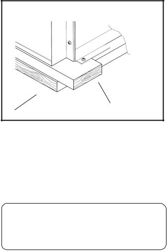
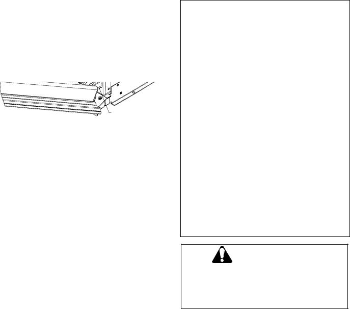
Figure 1 Oven Base Attachment
|
Remove Screws - |
Shipping base skid |
4 places |
The bottom trim is shipped, wrapped in waxed paper and is located on top of the unit. It should not be unpacked until the final step when the oven has been placed in the cabinet. See Fig. 6, Page 10.
 CAUTION
Unit is heavy and requires at least two persons or proper equipment to move.
3

STEP 2: CABINET PREPARATION
The cabinet cutout dimensions for wall mounted and under the counter installations are shown in Figs. 2 and 3, respectively.
It is good practice, when oven is installed at the end of a cabinet run, adjacent to a perpendicular wall or cabinet door, to allow at least 1/4" space between the side of the oven door and the wall/ door.
Wall Mounted Units
For oven support, install 2 x 4’s extending front to back flush with the bottom and the side of the opening.
The supporting base must be well secured to the floor/cabinet and level with the floor line.
Wall Mounted Installation
NOTE: The conduit box for double ovens (SEC272, SECD272, SEC302, SECD302, C272, C302, CM302, SEMW272 and SEM272) should be located above the unit to facilitate connecting and servicing. For single ovens (SEC301, C271, C301, and CM301) the conduit box may be installed either above or below the unit. If the conduit box is installed below the unit, a 2" diameter hole or space is required between the back wall and the right rear of the 2 x 4 supports. See Figure 2.
When an oven is installed, the cabinet base must be capable of supporting the oven weight as listed below:
O V E N |
POUNDS |
KILOGRAMS |
SE-series Single Oven |
165 |
75 |
|
|
|
C-series Single Oven |
210 |
95 |
|
|
|
CM Single Oven |
240 |
109 |
S-series Double Oven |
330 |
150 |
|
|
|
C-series Double Oven |
355 |
161 |
|
|
|
CM Double Oven |
370 |
168 |
|
|
|
Figure 2- Cabinet Cutout - Wall Mounted Installation Refer to dimensions for specific ovens on Page 5
FRONTVIEW SIDEVIEW
Preferred |
|
|
|
|
|
F |
|
|
|
|
|
|
|
|
|
|
|
|
|
G |
|||
|
|
|
|
|
|
|
|
|
|
|
|
|
|
|
|
|
|
||||||
|
|
|
|
|
|
|
|
|
|
|
|
|
|
|
|
|
|||||||
|
|
|
|
|
|
|
|
|
|
|
|
|
|
|
|
|
|
|
|
|
|
||
Location |
|
|
|
|
|
|
|
|
|
|
|
|
|
|
|
|
|
|
|
|
|
||
|
|
|
|
|
|
|
|
|
|
|
|
|
|
|
|
|
C |
||||||
of Conduit |
|
|
|
|
|
|
|
|
|
|
|
|
|
Frame |
|
||||||||
|
|
|
|
|
|
|
|
|
|
|
|
|
|
|
|||||||||
Box |
|
|
|
|
|
|
|
|
|
|
|
|
|
|
|
|
|||||||
|
|
|
|
|
|
|
|
|
|
|
|
Overlap |
|
|
|
||||||||
|
|
|
|
|
|
|
|
|
|
|
|
|
|
|
|
|
|
||||||
|
|
|
|
|
|
|
|
|
|
|
|
|
|
|
(Top) 3/8" |
|
|
|
|||||
|
|
|
|
|
|
|
|
|
|
|
|
|
|
(1, 0 cm) |
|
|
|
||||||
|
|
|
|
|
|
|
|
|
|
|
|
|
|
|
Cabinet |
|
|
|
|||||
A |
|
|
|
|
|
|
|
|
|
|
|
|
Recommended |
||||||||||
|
|
|
|
|
|
|
|
|
|
|
|
|
|||||||||||
|
|
|
|
|
|
|
|
|
|||||||||||||||
|
|
|
|
|
|
|
|
|
|
E |
|||||||||||||
|
|
|
|
|
2x4 |
Supports |
|
|
|
|
|
|
2" Diameter Hole (4.5 |
||||||||||
|
|
|
|
|
|
|
|
|
|
|
|||||||||||||
|
|
|
|
|
|
|
|
|
|
|
cm) |
|
|
|
|
|
|
|
|||||
|
|
|
|
|
|
|
|
|
|
|
|
|
|
|
|
|
|
||||||
|
|
|
|
|
|
|
|
Stud) |
|
|
|
|
|
|
|
|
|
|
|
|
|
||
|
|
|
|
|
|
|
|
|
|
|
|
|
|
|
|
|
|
|
|
|
|
||
|
|
|
|
|
(Wall |
|
|
|
|
|
|
|
|
|
|
|
|
|
|
|
|
||
|
|
|
|
|
|
|
|
|
|
|
|
|
|
|
|
|
|
|
|
|
|
|
|
|
|
|
|
|
|
|
|
|
|
|
|
|
|
Post Supports |
Exposed Edge |
||||||||
|
|
|
|
|
|
|
|
|
|
|
|
|
|
||||||||||
|
|
|
|
|
|
|
|
|
|
|
|
|
|
Must be a Finish- |
|||||||||
|
|
|
|
|
|
|
|
|
|
|
|
|
|
Required Near |
|||||||||
|
|
|
|
|
|
|
|
|
|
|
|
|
|
Cut |
|||||||||
|
|
|
|
|
|
|
|
|
|
|
|
|
|
Back |
H |
|
|
|
|
|
|
||
|
|
|
|
|
|
|
|
|
|
|
|
|
|
|
|
|
|
|
|||||
|
|
|
|
|
|
|
|
|
|
|
|
|
|
|
|
|
|
|
|
|
|
|
|
|
|
|
|
|
|
|
|
|
|
|
|
|
|
|
|
|
|
|
|
|
|
|
|
D |
|
|
|
|
|
B |
|
|
|
Side Frame |
|
|
|
|
|
|
|
||||||
|
|
|
|
|
|
|
|
Overlap |
|
|
|
|
|
|
|
||||||||
|
|
|
|
|
|
|
|
|
|
|
|
|
5/8" Cabinet |
|
|
|
|
|
|
|
|||
|
|
|
|
|
|
|
|
|
|
|
|
|
(1, 6 cm) |
|
|
|
|
|
|
|
|||
|
FLOOR |
|
|
|
|
|
|
|
|
|
|
|
|
|
|
|
|||||||
|
|
|
|
|
|
|
|
|
Conduit Box May be Placed |
||||||||||||||
|
LINE |
|
|
|
|
|
|
|
|
Here |
|
|
|
|
|
|
|
||||||
Double Oven
Location of
Conduit Box
2-1/2" (6, 4 cm)
Above Unit
CONDUIT BOX IS NOT FURNISHEDWITHUNIT
Approx. 5" (13 cm)
4
Table 1 - Cabinet Cutout DimensionsWall Mounted Installation
27" Built-In Electric |
Double |
Wall Ovens: C272, SEC272, SECD272 |
|
|
|
|
|||||
|
Cabinet |
Cutout |
Dimensions |
|
|
Overall Dimension |
|
|
|||
A (Height) |
B (Width) |
C (Depth) |
|
D (Floor to Cutout) |
E (Height)* |
F (Width)** |
G (Depth) |
H*** |
Door |
||
|
Extension |
||||||||||
51-1/8" |
25-1/2" |
|
24" |
|
9-3/4" |
51-1/2" |
26-3/4" |
23-7/8" |
22" |
||
(129, 9 cm) |
(64, 8 cm) |
(61, 0 cm) |
|
(24, 8 cm) |
(130, 8 cm) |
(68, 0 cm) |
(60, 6 cm) |
(55, 9 cm) |
|||
|
|
|
|
|
|
|
|
|
|
|
|
27" Built-In Electric |
Single |
Wall Ovens: C271, SEC271 |
|
|
|
|
|
||||
|
Cabinet |
Cutout Dimensions |
|
|
Overall Dimension |
|
|
||||
A (Height) |
B (Width) |
|
C (Depth) |
|
D (Floor to Cutout) |
E(Height)* |
F (Width)** |
G (Depth) |
H*** |
Door |
|
28-1/4" |
25-1/2" |
|
24" |
|
4-3/4" to 31-3/8" |
28-5/8" |
26-3/4" |
23-7/8" |
22"Extension |
||
(71, 8 cm) |
(64, 8 cm) |
|
(61, 0 cm) |
|
(12, 1 to 79, 7 cm) |
(72, 7 cm) |
(68, 0 cm) |
(60, 6 cm) |
(55,9 cm) |
||
|
|
|
|
|
|
|
|
|
|
|
|
27" Built-In Electric |
Wall |
Ovens: SEMW272 |
|
|
|
|
|
|||
|
Cabinet |
Cutout Dimensions |
|
|
Overall Dimension |
|
|
|||
A (Height) |
B (Width) |
C (Depth) |
|
D (Floor to Cutout) |
E (Height)* |
F (Width)** |
G (Depth) |
H*** |
Door |
|
55-3/8" |
25-1/2" |
24" |
|
9-3/4" |
55-3/4" |
26-3/4" |
23-7/8" |
22"Extension |
||
(140, 6 cm) |
(64, 8 cm) |
(61, 0 cm) |
|
(24, 8 cm) |
(141, 6 cm) |
(68, 0 cm) |
(60, 6 cm) |
(55, 9 cm)30" |
||
|
|
|
|
|
|
|
|
|
|
|
|
|
|
|
|
|
|
|
|
|
|
27" Built-In Electric |
Wall |
Ovens: SEM272 |
|
|
|
|
|
|
|||||||
|
|
Cabinet |
Cutout |
Dimensions |
|
|
|
|
Overall Dimension |
|
Door |
||||
A (Height) |
|
B (Width) |
|
C |
(Depth) |
|
D |
(Floor to Cutout) |
E |
(Height)* |
F (Width)** |
G (Depth) |
H*** |
||
|
|
|
Extension |
||||||||||||
46-1/8" |
25-1/2" |
|
|
24" |
|
|
19-1/2" |
46-1/2" |
26-3/4" |
23-7/8" |
22" |
||||
(117, 2 cm) |
|
(64, 8 cm) |
|
(61, 0 cm) |
|
|
(50 cm) |
(118, 1 cm) |
(68, 0 cm) |
(60, 6 cm) |
(55, 9 cm)30" |
||||
|
|
|
|
|
|
|
|
|
|
||||||
Built-In Electric Double Wall Ovens: C302, CM302, SEC302, SECD302 |
|
|
|
||||||||||||
|
|
Cabinet |
Cutout |
Dimensions |
|
|
|
|
Overall Dimension |
|
Door |
||||
A (Height) |
|
B (Width) |
|
C |
(Depth) |
|
D |
(Floor to Cutout) |
E |
(Height)* |
F (Width)** |
G (Depth) |
H*** |
||
|
|
|
Extension |
||||||||||||
51-1/8" |
28-1/2" |
|
|
24" |
|
|
9-3/4" |
51-1/2" |
29-3/4" |
23-7/8" |
22" |
||||
(129, 9 cm) |
|
(72, 4 cm) |
|
(61,0 cm) |
|
|
(24, 8 cm) |
(130, 8 cm) |
(75, 6 cm) |
(60, 6 cm) |
(55, 9 cm) |
||||
|
|
|
|
|
|
|
|
|
|
|
|
|
|||
30" Built-In Electric |
Single |
|
Wall Ovens: C301, CM301, SEC301 |
|
|
|
|
||||||||
|
|
Cabinet |
Cutout |
Dimensions |
|
|
|
|
Overall Dimension |
|
|
||||
A (Height) |
|
B (Width) |
|
C |
(Depth) |
|
D |
(Floor to Cutout) |
E |
(Height)* |
F (Width)** |
G (Depth) |
H*** |
|
|
28-1/4" |
28-1/2" |
|
|
24" |
|
|
4-3/4" to 31-3/8" |
28-5/8" |
29-3/4" |
23-7/8" |
22" |
||||
(71, 8 cm) |
|
(72, 4 cm) |
|
(61, 0 cm) |
|
(12, 1 to 79, 7 cm) |
(72, 7 cm) |
(75, 6 cm) |
(60, 6 cm) |
(55,9 cm) |
|||||
30" Built-In Electric |
Double |
Wall Oven: SEM302 |
|
|
|
|
|
|
|||||||
|
|
|
|
|
|
|
|
|
|
|
|
|
|
|
|
|
|
Cabinet |
Cutout |
Dimensions |
|
|
|
|
Overall Dimension |
|
|
||||
A (Height) |
|
B (Width) |
|
C |
(Depth) |
|
D |
(Floor to Cutout) |
E |
(Height)* |
F (Width)** |
G (Depth) |
H*** |
|
|
46-1/8" |
28-1/2" |
|
|
24" |
|
|
19-1/2" |
46-1/2" |
29-3/4" |
23-7/8" |
22" |
||||
(117, 2 cm) |
|
(72, 4 cm) |
|
(61, 0 cm) |
|
|
(38, 7 cm) |
(118, 1 cm) |
(75, 6 cm) |
(60, 6 cm) |
(55, 9 cm) |
||||
|
|
|
|
|
|
|
|
|
|
|
|
|
|||
30" Built-In Electric |
Double |
Wall Oven: SEMW302 |
|
|
|
|
|
|
|||||||
|
|
Cabinet |
Cutout |
Dimensions |
|
|
|
|
Overall Dimension |
|
|
||||
A (Height) |
|
B (Width) |
|
C |
(Depth) |
|
D |
(Floor to Cutout) |
E |
(Height) |
F (Width) |
G (Depth) |
H*** |
|
|
55-3/8" |
|
28-1/2" |
|
|
24" |
|
|
9-3/4" |
55-3/4" |
29-3/4" |
23-7/8" |
22" |
|||
(140, 6 cm) |
|
(72, 4 cm) |
|
(61, 0 cm) |
|
|
(50 cm) |
(141, 6 cm) |
(75, 6 cm) |
(60, 6 cm) |
(55, 9 cm) |
||||
|
|
|
|
|
|
|
|
|
|
||||||
* Add 1/16" for stainless steel ovens (SESeries Ovens Only) |
** Add 1/8" for stainless steel ovens (S- Series |
||||||||||||||
Ovens Only) |
|
|
|
|
|
|
|
|
|
|
|
|
|
|
|
*** Measured from cabinet face, largest door. |
|
|
|
|
|
|
|||||||||
5
STEP 2: CABINET PREPARATION Continued
Under-the-counter Units
A single oven (SEC301, C301or CM301) installed under the counter allows for the installation of most Thermador Gas or Electric non-Cook'n'Vent® Model Cooktops. (See Table 2 for recommended cooktop models.) Downdraft units cannot be installed in this configuration; Thermador overhead ventilation is recommended.
Some TMH cooktops require additional clearances to combustible walls.
NOTE: The Thermador Oven Models SEC301, C301 or CM301 under the counter and cooktop combination are a UL and CUL approved installation.
A Thermador cooktop should be installed on the same center line as the under-the-counter single oven. Follow the installation instructions provided with cooktop for installation of cooktops. Three
(3) inches (7.5 cm) minimum is required from the top of the countertop to the top of the cutout opening (see Figure 3d) for under-counter installation with Thermador cooktops (see Table 1, Page 6). If the type of cabinet or countertop thickness does not provide for this minimum space, the cabinet base may have to be lowered, into the toe space, to provide the necessary space above the oven.
Side-by-side Units
The minimum distance required for side-by-side installation is 2 inches (5, 1 cm) from one vertical edge of the cabinet cutout to the adjacent edge of the next cabinet cutout. Use only Thermador Trim Piece D30SXSB (black) or D30SXSW (white) for side-by- side installation in place of the standard cabinet face between the 2 ovens. This will leave a 3/4" (2 cm) space from one vertical edge of the door to the adjacent edge of the other door. Do not install a cabinet wall partition between the two ovens.
|
Table 2 |
|
|
|
|
Under-the-counter Installation with |
|
|
|
|
Thermador |
Cooktops |
|
|
|
|
|
|
|
Model |
Type of Cooktop |
Model |
Type |
of Cooktop |
Number |
|
Number |
|
|
|
|
|
|
|
CEM304 |
|
SGS304 |
|
|
CEM365 |
Glass Ceramic top - electric |
SGS365 |
Steel |
top - gas |
CEM465 |
|
SGS456 |
|
|
CET356 |
|
SGSX304 |
|
|
CEP304 |
|
SGSX365 |
|
|
CEP365 |
|
SGSX456 |
|
|
CEP456 |
|
SGSX26G |
|
|
6
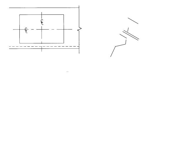
Figure 3 - Cabinet Cutout - 30" Single Oven Under-the-counter Installation
Fig. 3a |
|
|
Figure 3b |
|
|
|
|
|
|
||||||||||||||||
|
|
|
|
|
|
|
|
|
|
|
|
|
|
CUT |
OUT |
|
|
|
|
|
|
||||
|
|
|
|
|
|
|
|
|
|
|
|
|
|
|
|
|
|
|
|
|
|
||||
|
|
|
|
|
|
|
|
|
|
|
|
|
CUT |
OUT |
|
|
|
|
|
|
|
|
|
||
|
|
|
|
|
|
|
|
|
|
|
|
|
Floor |
|
|
|
|
|
|
|
|
|
|||
|
|
|
|
|
|
|
|
|
|
|
|
|
Line |
|
|
|
|
3" |
Min |
|
|
|
|||
|
|
|
|
|
|
|
|
|
|
|
|
|
|
|
|
|
|
|
|
|
|||||
|
|
|
|
|
|
|
|
|
|
|
|
|
|
|
|
|
|
|
|
|
|
|
|
||
|
|
|
|
|
|
|
|
|
|
|
|
|
|
|
|
|
|
|
|
|
|
|
|
|
|
|
|
|
|
|
|
|
|
|
|
|
|
|
|
|
|
|
|
|
|
|
|
. |
|
|
|
|
|
|
|
|
|
|
|
|
|
|
|
|
|
|
|
|
|
|
|
|
(7, |
|
|||
|
|
|
|
|
|
|
|
|
|
|
|
|
|
|
|
|
|
|
|
6 |
|||||
Cooktop Cutout - See |
|
|
|
|
|
|
|
|
|
|
|
|
|
|
cm) |
||||||||||
Cooktop Installation |
|
|
|
|
|
|
|
|
|
|
|
28-1/4" |
|||||||||||||
Instructions |
|
|
|
|
|
|
|
|
|
|
|
|
|
|
|
28-1/2" |
|
||||||||
|
|
|
|
|
|
||||||||||||||||||||
|
|
|
|
|
|
|
|
|
|
|
|
|
|
|
|
|
|
|
|
||||||
|
|
|
|
|
|
|
|
|
|
|
|
|
|
|
(72, 4 cm) |
|
|
|
|
|
|||||
|
|
|
|
|
|
|
|
|
|
|
|
|
|
|
|
|
|
|
|
||||||
|
|
|
|
|
|
|
|
|
|
|
|
|
|
|
|
|
|
|
|
|
|
||||
|
|
|
|
|
|
|
|
|
|
|
|
|
4" (10, 2 cm) Nominal Toe Space See |
|
Fig. 2 |
||||||||||
|
|
|
|
|
|
|
|
|
|
|
|||||||||||||||
|
|
|
|
|
|
|
|
|
|
|
|
|
|||||||||||||
|
|
|
|
|
|
|
|
|
|
|
|
|
|
|
|
|
|
|
|
|
|
|
|
|
|
Fig. 3c |
|
|
Figure 3d (SEC301; C301; CM301) |
||||||||||||||||||||||
16-1/2" |
|
|
|
|
|
|
|
|
|
|
|
|
|
|
|
||||||||||
|
|
|
|
|
|
|
|
(41, 9 cm) |
|
J-Box |
|
|
3" (7, 6 cm) minimum |
|
|
|
|
|
|||||||
|
|
|
|
|
|
|
|
|
|
|
|
|
|
||||||||||||
|
|
|
|
|
|
|
|
|
|
|
|
|
|
|
|
|
|
|
|||||||
|
|
|
|
|
|
|
|
|
|
|
|
|
|
|
|
|
|
|
|
|
|
|
|
|
|
|
|
|
|
|
|
|
|
|
|
|
|
Conduit |
|
|
|
|
|
|
|
|
|
|
|
|
|
|
|
|
|
|
|
|
|
|
|
|
|
|
|
|
|
|
|
|
|
|
|
4-1/8" |
|
|
|
|
|
|
|
|
|
|
|
|
|
|
|
|
|
|
|
|
|
|
|
|
|
|
|||
Frame |
|
|
|
|
|
|
|
|
|
36" |
|
|
|
|
|
|
|
(10, 5 cm) |
|
||||||
|
|
|
|
|
|
|
|
|
|
|
28-1/4" |
|
|
|
|
|
|||||||||
Overlap |
|
|
|
|
|
|
|
|
(91 cm) |
|
(71, 8 cm) |
|
|
|
|
|
|||||||||
3/8" |
|
|
|
|
|
|
|
|
|
|
|
|
|
|
|
|
|
|
|
|
|||||
|
|
|
|
|
|
|
|
|
|
|
|
|
28-5/8" |
|
|
|
|
|
|
|
|
||||
|
|
|
|
|
|
|
|
|
|
|
|
|
|
|
|
|
|
|
|
|
|||||
(1, 0 cm) |
|
|
|
|
|
|
|
18" |
|
(72, 7 cm) |
|
3/4" |
|
|
|
|
|
||||||||
|
|
|
|
|
|
|
|
|
|
|
|
|
|
||||||||||||
Cabinet |
|
|
|
|
|
|
|
(45, 7 cm) |
|
|
|
|
|
|
|
|
|
|
|
|
|||||
|
|
|
|
|
|
|
|
|
|
|
|
|
|
|
|
|
|
|
|
||||||
|
|
|
|
|
|
|
|
|
|
|
|
|
|
|
|
|
|
|
|
(1, 9 cm) |
|
|
|
|
|
|
|
|
|
|
|
|
|
|
|
|
|
Frame Overlap |
|
|
|
4" (10, 2 cm) |
|
|
|
|
|
||||
28-1/2" |
|
|
|
|
|
|
2x4 |
|
|
|
|||||||||||||||
|
|
|
typ. 5/8" |
|
|
|
Nominal Toe |
|
|
|
|||||||||||||||
|
|
|
|
|
|
|
|
(72, 4 cm) |
|
cabinet |
|
|
|
Space |
(Wall Stud) |
|
|||||||||
|
|
|
|
|
|
|
FRONT VIEW |
|
|
(1.5 cm) |
|
|
|
|
|
|
SIDE VIEW |
Supports |
|
||||||
|
|
|
|
|
|
|
|
|
|
|
|
|
|
|
|||||||||||
|
|
|
|
|
|
|
|
|
|
|
|
|
|
|
|
|
|
|
|
|
|||||
|
|
|
|
|
|
|
|
|
|
|
|
|
|
|
|
|
|
|
|
|
|
|
|
|
|
7

STEP 3: ELECTRICAL INSTALLATION
All model ovens on the front cover are dual rated, designed to be connected to either 120/240V AC or 120/208V AC, 60 Hz, 4 wire, single-phase power supply.
MODEL |
CIRCUIT REQUIRED |
|
|
|
|
|
208 Volt, 60 Hz |
240 Volt, 60 Hz |
|
|
|
SEC301, SEC271, |
25 AMP |
30 AMP |
C271, C301 |
|
|
|
|
|
CM301 |
30 AMP |
30 AMP |
|
|
|
SEC272, SECD272, |
40 AMP |
40 AMP |
C272, SEC302, SECD302, |
|
|
C302, SEM272, SEM302, |
|
|
SEMW272, SEMW302 |
|
|
|
|
|
CM302 |
50 AMP |
50 AMP |
|
|
|
 CAUTION
After turning power OFF at the service panel, lock service panel.
The electrical supply should be a 4-wire single-phase AC. Install a suitable conduit box (not furnished) as shown in Figures 2 or 3.
Electrical Connection
1.Connect the red oven wire to the red electrical supply wire (hot wire).
2.Connect the black oven wire to the black electrical supply wire (hot wire).
3.Connect the white neutral oven wire to the white neutral (not bare ground) electrical supply wire.
4.Connect the bare ground oven wire to the bare ground electrical supply wire.
The conduit cable, where connected at the oven, swivels. Rotate conduit cable upward (or downward) and direct through hole prepared in cabinet to attach to J-Box.
To facilitate service, the flex conduit must not be shortened and should be routed to permit temporary removal of the oven.
GROUNDING
IMPORTANT: Local Codes might vary, installation, electrical connections and grounding must comply with all applicable local codes.
If local codes permit grounding through the electrical supply neutral, connect both the white neutral wire and the bare ground wire from the oven to the white neutral electrical supply wire.
208V ELECTRICAL HOOKUP
The following applies to the controls on the C271, C272, C301, C302, CM301 and CM302 models only.
Your oven has been preset to be hooked up to 240V.
1.Turn both ovens off. Touch OVEN OFF for each oven.
2.Touch and hold the START pad followed by the SELF CLEAN pad together for 3 seconds.
3.“240” appears in the display. Release both pads.
4.Touch the SELF CLEAN pad. “240” is replaced by with “208.” This alternates when SELF CLEAN is touched.
5.To complete the change, touch START.
NOTE: When power is first supplied to the unit (and the door is unlocked), the CLOCK will flash. Set Time of Day as described in the Care and Use Manual. If the door is locked, the LOCK symbol will light for a few seconds while door is automatically unlocking and CLOCK will flash.
Note: All models can operate on 100/208 power.
8
STEP 4: INSTALLING THE OVEN
Removing the Oven Door
(CM301 oven door and CM302 upper door are not removable).
For ease of installation, some oven door(s) may be removed to reduce the weight of the oven by 30 pounds per door, before installing into the cabinet. See instructions below.
Fig. 4
HINGE CLIP
HINGE ARM
Door Hinge Close-up View
To Remove the Oven Door
1.Fully open the oven door.
2.Raise the U-clip over the hook on each of the hinges to the "locked" position (see illustration above). This will prevent the hinge from snapping closed when the door is removed.
3.Grasp the door by the sides toward the back. Raise the front of the door several inches (there will be some spring resistance to overcome because of the hinge being locked). When the front of the door is high enough, you will be able to lift the hinges to clear the indents.
4.Pull the hinges out of the slots in the oven front frame.
Remove the Bottom Trim
Remove the bottom trim from the top of the unit. Remove the base skid. See Figure 1 (Page 3) and Figure 5, Page 10.
Slide the Oven into Opening
Slide the oven into the opening being careful not to scratch side trims. Secure oven with the 4 screws provided (2 each side) through the side of the front frame into the cabinet.
Replace the Door(s)
After installing the unit, replace the door(s); be certain both hinge arms are well inserted and secure, and that the hinge latch is fully released.
 CAUTION:
DO NOT MOVE OR LIFT OVEN BY DOOR HANDLE. DOOR GLASS BREAKAGE MAY OCCUR.
THE DOOR OF THE CM301 AND THE UPPER DOOR OF THE CM302 ARE NOT REMOVABLE BECAUSE THEY ARE PART OF MICROWAVE SEAL.
USE CAUTION WHEN REMOVING THE DOOR(S). DOORS ARE VERY HEAVY.
•The oven doors are heavy and fragile. Use both hands to remove or replace the door.
•Grasp only the sides of the oven door
when removing or replacing it.
•Failure to grasp the oven door firmly and properly could result in personal injury and product damage.
•With the door off, never release the levers and try to close the hinges. Without the weight of the door, the powerful springs will snap the hinges closed with great force.
WARNING
To avoid injury from hinge bracket snapping closed, be sure that both levers are securely in place before removing door.
Also, do not force door open or closed - the hinge could be damage and injury could result.
IMPORTANT: Reinstall the door very carefully. Be certain that the hinge arm does not hit the porcelain collar around the clearance slot or it will chip the porcelain.
To Replace the Oven Door
1.Grasp the sides of the door at the center and insert the ends of the hinges into the slots in the oven front frame as far as they will go (see illustration below).
2.With the door open all the way, lower the two locking clips.
3.Raise the oven door and make sure that it fits evenly with the front sides.
4.Close and open door slowly to be sure it is correctly and securely in place.
9
STEP 5: INSTALLING THE BOTTOM TRIM
Install the bottom vent trim and secure with the 2 screws provided, one at each top end corner of the trim. The sheet metal bottom of the oven should be under the trim, except for the section at the center. To install the screws, open the door. The holes are visible at each end below the left and right hinges. Place and tighten screws. See Fig. 5 View 'A'.
View 'A'
Side View 'A'
Fig. 5 - Installing Bottom Trim
STEP 6: INSTALLING THE OVEN RACKS
Grasp rack rack firmly on both sides. Tilt rack up to allow stop into rack holder. Bring rack to a horizontal position and push the rest of the way in. Rack should be straight and flat, not crooked.
 CAUTION
Always insert racks with pot stops toward the back of the oven and facing up. If inserted incorrectly, the rack could come all the way out of the oven causing injury and/or burns
10
 Loading...