


LP GAS CONVERSION and
HIGH ALTITUDE ADJUSTMENT
INSTRUCTIONS
For THERMADOR PROFESSIONAL® Pro Grand
Dual Fuel Ranges
INSTRUCTIONS DE CONVERSION AU GPL et D’ADJUSTEMENT POUR HAUTES ALTITUDES
Pour les cuisinières mixtes au gaz PROFESSIONALmc Pro Grand de THERMADOR
INSTRUCCIONES DE CONVERSION DE GAS LP y CONVERSIÓN PARA GRANDES ALTITUDES
Para las estufas mixtas PROFESSIONAL® Pro Grand de THERMADOR
Models/
Modèles/
Modelos:
PRD364JDGC
PRD364JDGU
PRD364NLGC
PRD364NLGU
PRD366JGC
PRD366JGU
PRD484NCGC
PRD484NCGU
PRD486NLGC
PRD486NLGU
PRD486JDGC
PRD486JDGU
PRD48JDSGC
PRD48JDSGU
PRD48NCSGC
PRD48NCSGU
PRD48NLSGC
PRD48NLSGU
PRD606RCG
PRD606REG
PRD606RCSG
PRD606RESG

Table of Contents
Safety. . . . . . . . . . . . . . . . . . . . . . . . . . . . . . . . . . . . . . . . . . . . . . . . . . . . . . . . . . . . . . . . . . . . . . . . . . . . . . . . . . . . . . . 2
Important Safety Instructions. . . . . . . . . . . . . . . . . . . . . . . . . . . . . . . . . . . . . . . . . . . . . . . . . . . . . . . . . . . . . . . . . . 2
LP Gas Conversion Instructions . . . . . . . . . . . . . . . . . . . . . . . . . . . . . . . . . . . . . . . . . . . . . . . . . . . . . . . . . . . . . . . . 3
Before You Begin . . . . . . . . . . . . . . . . . . . . . . . . . . . . . . . . . . . . . . . . . . . . . . . . . . . . . . . . . . . . . . . . . . . . . . . . . . 3 LP Conversion Preparation . . . . . . . . . . . . . . . . . . . . . . . . . . . . . . . . . . . . . . . . . . . . . . . . . . . . . . . . . . . . . . . . . . . 3 Disassembling the Cooktop. . . . . . . . . . . . . . . . . . . . . . . . . . . . . . . . . . . . . . . . . . . . . . . . . . . . . . . . . . . . . . . . . . . 3 LP Regulator Conversion . . . . . . . . . . . . . . . . . . . . . . . . . . . . . . . . . . . . . . . . . . . . . . . . . . . . . . . . . . . . . . . . . . . . 4 Replacing the Burner Orifices . . . . . . . . . . . . . . . . . . . . . . . . . . . . . . . . . . . . . . . . . . . . . . . . . . . . . . . . . . . . . . . . . 5 Reassemble the Cooktop . . . . . . . . . . . . . . . . . . . . . . . . . . . . . . . . . . . . . . . . . . . . . . . . . . . . . . . . . . . . . . . . . . . . 6
High Altitude Adjustment Instructions and Setting Valve Screws
for LP Converted Burners . . . . . . . . . . . . . . . . . . . . . . . . . . . . . . . . . . . . . . . . . . . . . . . . . . . . . . . . . . . . . . . . . . . . . . 7
Setting Valve Screws. . . . . . . . . . . . . . . . . . . . . . . . . . . . . . . . . . . . . . . . . . . . . . . . . . . . . . . . . . . . . . . . . . . . . . . . 7 Check for Gas Leaks . . . . . . . . . . . . . . . . . . . . . . . . . . . . . . . . . . . . . . . . . . . . . . . . . . . . . . . . . . . . . . . . . . . . . . . . 8 Checking manifold pressure (if necessary) . . . . . . . . . . . . . . . . . . . . . . . . . . . . . . . . . . . . . . . . . . . . . . . . . . . . . . . 8 Check Flame Characteristics. . . . . . . . . . . . . . . . . . . . . . . . . . . . . . . . . . . . . . . . . . . . . . . . . . . . . . . . . . . . . . . . . . 9 Conversion Label Placement. . . . . . . . . . . . . . . . . . . . . . . . . . . . . . . . . . . . . . . . . . . . . . . . . . . . . . . . . . . . . . . . . 10
Customer Support, Accessories & Parts . . . . . . . . . . . . . . . . . . . . . . . . . . . . . . . . . . . . . . . . . . . . . . . . . . .back page
Install Scenarios
Scenario |
Complete |
|
|
Pages |
|||
|
|||
|
|
|
|
|
|
|
|
Natural gas with High Altitude adjustment |
7 – 10 |
||
|
|
|
|
Natural gas to LP Conversion |
3 – 10 |
||
|
|
|
|
Natural gas to LP Conversion with High |
3 – 10 |
||
Altitude adjustment |
|
|
|
|
|
|
|
Safety Definitions
WARNING
This indicates that death or serious injuries may occur as a result of non-observance of this warning.
CAUTION
This indicates that minor or moderate injuries may occur as a result of non-observance of this warning.
NOTICE: This indicates that damage to the appliance or property may occur as a result of non-compliance with this advisory.
Note: This alerts you to important information and/or tips.
|
This THERMADOR® appliance is made by |
|
BSH Home Appliances Corporation |
|
1901 Main Street, Suite 600 |
|
Irvine, CA. 92614 |
|
Questions? |
|
1-800-735-4328 |
|
www.thermador.com |
|
We look forward to hearing from you! |
Table of Contents |
English | 1 | |
Safety
IMPORTANT SAFETY INSTRUCTIONS
READ AND SAVE THESE INSTRUCTIONS
The LP Conversion Kit is used to convert THERMADOR PROFESSIONAL® PRO GRAND® dual fuel ranges, from natural gas to propane (LP) gas operation. This kit cannot be used to convert older models of THERMADOR PROFESSIONAL rangetops or ranges other than those identified in these instructions (see applicable models on the front cover). The LP Conversion Kit cannot be used to convert all-gas ranges, oven burners, or any other brand of appliance.
Save the natural gas parts for possible conversion from LP back to the natural gas in the future.
IMPORTANT: Only a qualified service technician or installer should make this conversion.
INSTALLER: Please leave these conversion instructions with this unit for the owner.
OWNER: Please retain these instructions for future reference.
CAUTION
Disconnect gas and electric power before making conversion or adjustments. Before turning power ON, be sure that all controls are in the OFF position.
WARNING
This conversion kit shall be installed by a qualified service agency in accordance with the manufacturer’s instructions and all applicable codes and requirements of the
authority having jurisdiction. If the information in these instructions is not followed exactly, a fire, explosion or production of carbon monoxide may result causing property damage, personal injury or loss of life. The qualified service agency is responsible for the proper installation of this kit. The installation is not proper and complete until the operation of the converted appliance is checked as specified in the manufacturer’s instructions supplied with the kit.
To the Service Agent:
It is important that you know the following BEFORE you begin the gas conversion of the appliance.
•Verify the type of gas supplied to the location. Ensure that the appliance is connected to the type of gas for which it is certified.
•If the Dual Fuel range is to be converted for Propane (LP) Gas, the appliance must first be converted for use with Propane (LP) Gas before it can be converted for use at high altitude. A Propane (LP) Conversion Kit is available for purchase from Thermador Customer Service. It is required that a qualified Professional install the Propane (LP) Conversion Kit.
•You must plan for sufficient time and resources to perform the LP conversion process properly and completely before leaving the job site. Every step described in these instructions must be performed to safely convert the appliance for proper operation on Propane Gas. INCOMPLETE OR INADEQUATE GAS
CONVERSION OF THE APPLIANCE CAN CREATE A SAFETY HAZARD.
WARNING
State of California Proposition 65 Warnings:
This product contains chemicals known to the State of California to cause cancer, birth defects or other reproductive harm.
WARNING
If the Natural Gas orifices are left in place while attempting to operate the appliance using Propane (LP) Gas, at the higher pressure setting for LP Gas, the burners will produce large flames which may emit high levels of carbon monoxide into the room, or a fire or explosion may occur.
WARNING
NEVER leave the gas conversion partially completed. If the appliance is operated while the gas conversion is incomplete, high levels of carbon monoxide may be emitted, or a fire or explosion may occur.
Installation Instructions |
English | 2 | |
LP Gas Conversion Instructions
Before You Begin |
Disassembling the Cooktop |
|
|
|
|
CAUTION
BEFORE PROCEEDING WITH THE CONVERSION, SHUT OFF THE GAS SUPPLY TO THE APPLIANCE PRIOR TO DISCONNECTING THE ELECTRICAL POWER.
TOOLS NEEDED
Scissors
T-30 Torx screwdriver
T-20 Torx screwdriver
1/4" nut driver
7/8" socket or adjustable wrench
Flat-head screwdriver, 1/8" X.020" blade (included)
CAUTION
When connecting the unit to propane gas, make certain the propane gas tank is equipped with its own high pressure regulator. The maximum gas pressure to this appliance is not to exceed 14.0 inches water column from the propane gas tank regulator.
IMPORTANT: Ensure that the power is turned OFF at the breaker and the gas supply is turned OFF.
1.Remove the cooktop grates.
2.Remove the burner caps.
3.From each burner base, remove the two burner base screws with a T-30 Torx screwdriver.
4.To facilitate the removal of the spill trays remove the T- 20 Torx stainless screws in the front face of the included Flush Island Trim.
LP Conversion Preparation
1.Shut off the gas supply to the appliance prior to disconnecting the electrical power.
2.Cut a 3/8" long piece of the adhesive foam tape (included). Place foam tape over the edge of the nut driver used to replace the burner orifices, as shown.
The foam tape helps to retain the orifice in the end of the nut driver so it will not fall inside the appliance during orifice removal or installation.
Installation Instructions |
English | 3 | |

5.Disconnect the igniter.
A.) Disconnecting a Two Piece Igniter
1)Carefully pull up on the burner base.


 Burner Base
Electrode
Ignitor Housing
Ignitor Wire 
B.) Disconnecting a Single Piece Igniter
1)Carefully pull up on the burner base.
2)Disconnect the female terminal on the spark wire from the male terminal on the electrode for each burner.
IMPORTANT: The locking tab on the female connector must be depressed to release from the terminal on the electrode.
Burner Base |
Electrode
 Ignitor Wire
6.From each burner pedestal, remove the burner pedestal screws with a T-30 Torx screwdriver.
Burner Pedestal


 Venturi
7.Carefully remove the burner pedestal and the venturi.
8.Remove the spill trays by rotating the trays up and out the back.
9.Remove the heat shield, on some models. Some models have a double-width shield that extends under adjacent spill tray.
LP Regulator Conversion
The gas regulator is located in the cooktop, left side of appliance. Exact location will vary per model.
1. Remove conversion cap with a 7/8" socket or wrench.
2.Read the letters on the stem. You will see “NAT” at the bottom of the stem. Snap-out the plunger from bottom of the conversion cap. Flip the stem over to the "LP" end, and snap the plunger back into the cap, as shown.
NAT |
LP |
|
Installation Instructions |
English | 4 | |
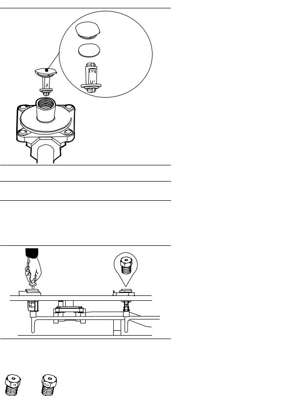
3.Re-install conversion cap, configured for LP gas, back into top of the regulator.
 Brass Cap
 Sealing Washer
 Plunger
 Regulator Body
Replace the Burner Orifices
1.Use a 7 mm or a 9/32'' socket with 1/4'' nut driver to reach down through the jet holders and remove the Natural Gas orifice from the burner’s jet holder.
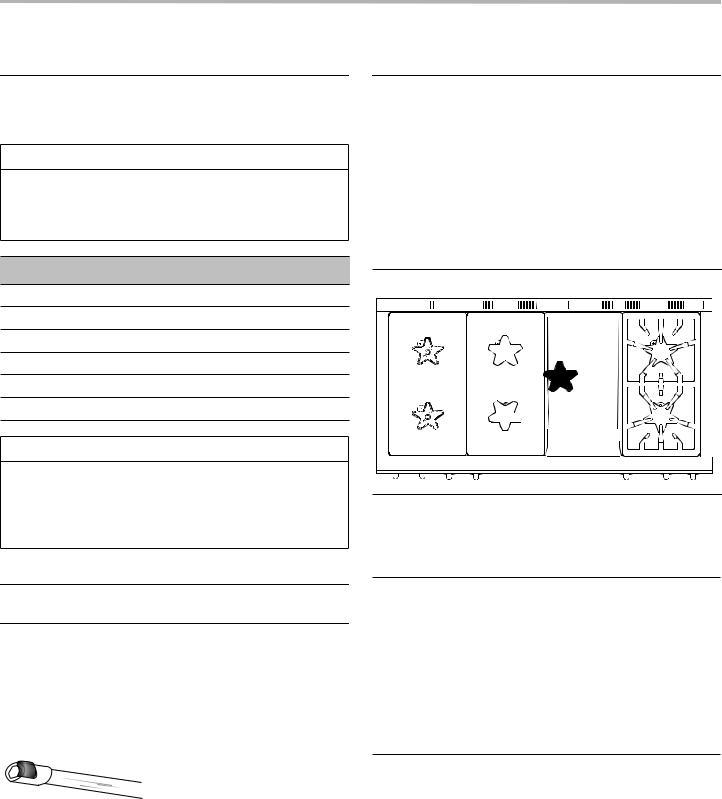
2.Locate the proper LP surface burner orifices included with the kit.
Orifices are stamped with the orifice diameter size on the side.
Orifice locations for 36'' models with 4 burners
Burner |
Orifice Size |
BTU Rate LP |
|
|
|
Left front (XLO) |
1.15 |
15,000 |
|
|
|
Left rear (XLO) |
1.15 |
15,000 |
|
|
|
Right front (XLO) |
1.25 |
18,000 |
|
|
|
Right rear (XLO) |
1.15 |
15,000 |
|
|
|
Orifice locations for 36'' and 48'' models with 6 burners
Burner |
Orifice Size |
BTU Rate LP |
|
|
|
Left front (XLO) |
1.15 |
15,000 |
|
|
|
Left rear (XLO) |
1.15 |
15,000 |
|
|
|
Center front |
1.15 |
15,000 |
|
|
|
Center rear |
1.15 |
15,000 |
|
|
|
Right front (XLO) |
1.25 |
18,000 |
|
|
|
Right rear (XLO) |
1.15 |
15,000 |
|
|
|
Orifice locations for 60'' models with 6 burners |
||
|
|
|
Burner |
Orifice Size |
BTU Rate LP |
|
|
|
Left front (XLO) |
1.25 |
18,000 |
|
|
|
Left rear (XLO) |
#62 |
11,000 |
|
|
|
Center front |
1.15 |
15,000 |
|
|
|
Center rear |
#62 |
11,000 |
|
|
|
Right front (XLO) |
1.15 |
15,000 |
|
|
|
Right rear (XLO) |
#64 |
9,100 |
|
|
|
3.Install the orifices in their correct location according to the tables above.
•All of the replacement orifices in the conversion kit have straight threads (not pipe threads) and do not require thread sealing compound.
4.Perform a gas leakage test of each orifice and associated supply tube fittings. See “Check for Gas Leaks” on page 8.
•Leak-checking should occur after the orifice conversion is complete, and before the burner is reassembled and tested.
Installation Instructions |
English | 5 | |

Reassemble the Cooktop
1.For the single piece igniter, carefully feed the wires through the heat shields, if applicable. Ensure that the igniter wires do not crimp.
For the two piece igniter, reinstall the heat shield, if applicable (wire feed not necessary).
2.For the single piece igniter, carefully feed the wires through the spill trays. Ensure that the igniter wires do not crimp.
For the two piece igniter, reinstall the spill trays (wire feed not necessary).
3.Reinstall the Flush Island Trim with T-20 Torx screws.
4.For the single piece igniter, carefully feed the igniter wires through the burner pedestals.
For the two piece igniter, reinstall the burner pedestals (wire feed not necessary).
5.Insert the venturi into the burner pedestals. Secure with the black T-30 Torx screws, starting both before fully securing either screw. Ensure that the venturi does not ‘lock down’. The venturi should be pulled out smoothly and easily once the pedestals have been secured.
6.For the single piece igniter, reconnect the igniter wire to the electrode on the burner base. Carefully feed the igniter wires back through their burner pedestals while setting the burner bases back into place. Ensure that the wires do not crimp or bunch.
For the two piece igniter, set the burner bases back on the burner pedestals (wire feed not necessary).
7.Secure with the burner bases with T-30 Torx screws, starting both before fully securing either screw.
8.Replace burner caps and grates.
Continue to “Setting Valve Screws” on page 7.
Installation Instructions |
English | 6 | |
High Altitude Adjustment Instructions and Setting Valve Screws for LP Converted Burners
Dual Fuel ranges converted for Propane (LP) Gas
For appliances that are to be converted to LP and must also have a High Altitude Adjustment, the appliance must first be converted for use with Propane (LP) Gas (service number 00553182) before it can be converted for use at high altitude. It is required that a qualified professional install both the Propane (LP) Conversion Kit and make the High Altitude Adjustment.
Setting Valve Screws
A flat-head screwdriver with
an 1/8" [3.0 mm] wide, .020"
[0.50 mm] thickness tip
(included) is used to
reposition the valve screws
 Valve Screw for minimum flow settings on
  manual valves.
Remove the protective cap before use.
1.SHUT OFF THE GAS SUPPLY TO THE APPLIANCE.
2.DISCONNECT THE ELECTRICAL POWER.
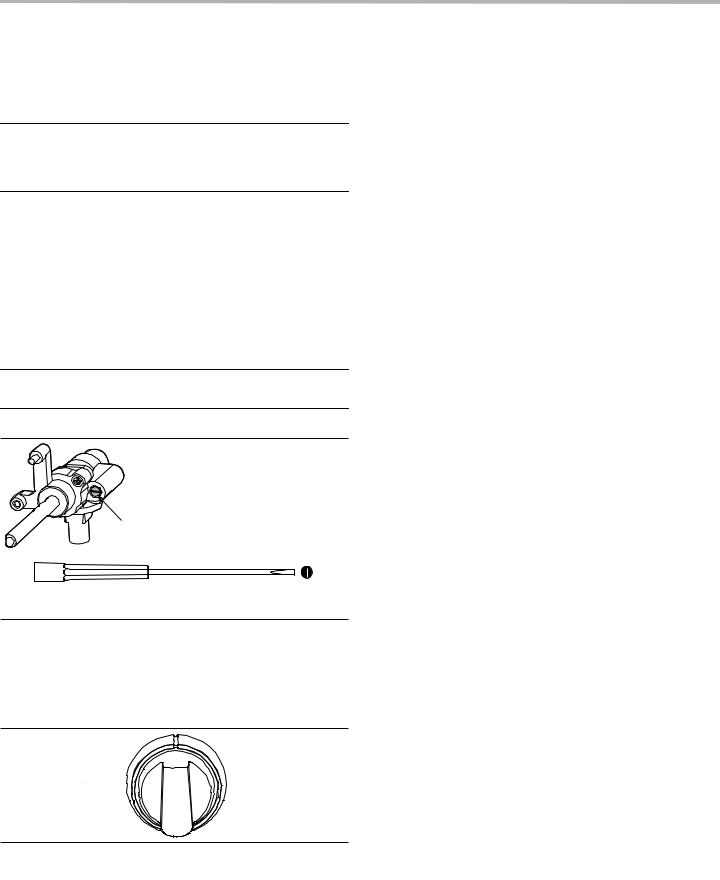
3.Remove knob from the valve stem by slowly pulling knob straight out, away from the control panel.
4. Remove the bezel-mounting screw located to the right of the valve stem, using a T-20 Torx driver.
5. To engage the valve screw, insert the included flat-blade screwdriver with 1/8'' blade into the hole in the bezel created by removal of the mounting screw. You should feel the engagement of the screwdriver and the valve screw.
6.FOR STANDARD BURNERS, adjust the valve screw by turning the valve screw clockwise about an
1/8 turn. Adjust the valve screw as little as required to reach satisfactory simmer results. Due to normal fluctuations in gas pressure, over-adjustment of valve screw may affect flame stability.
7.FOR EXTRALOW BURNERS, auto-cycling of the XLO® burners allows for exceptional simmer results and adjustment is not required. However, adjustment to the valve screw may be performed to suit individual preference. Always turn OFF the power to the appliance before adjusting flame settings. Turn the valve stem to the LOW position for proper access to the valve screws through clearance holes in the potentiometers.
By-pass screw access |
By-pass screw access |
hole with valve in OFF |
hole with valve in LOW |
position. |
position. |
Installation Instructions |
English | 7 | |
Check for Gas Leaks
WARNING
DO NOT use a flame of any kind to check for gas leaks.
Gas leakage checking using a liquid solution
Leak-checking should occur after the orifice conversion is complete, and before the burner is reassembled and tested.
1.Make sure that all of the LP orifices have been tightened and that all valves and controls are in the OFF position.
2.Turn on electrical and gas supplies.
3.Spray a generous amount of soap and water mixture— or other solution designed for checking gas leaks—on the threaded junction at the base of the orifice. Avoid spraying electrical devices. (A 25% dishwashing liquid to water mixture is effective for this.)
4.Briefly turn on the valve or control while blocking the orifice hole with a soft pencil eraser, your finger, or something similar. It is normal to hear spark ignition noise during this process.
5.Monitor the base of the orifice junction to see if bubbles are forming anywhere around the threaded connection.
•Bubbles forming are indications of gas leaks. The amount and sizes of the bubbles are indications of the severity of the leakage.
6.Repair all gas leaks immediately after their discovery; this can often be accomplished by re-tightening the orifice.
7.Since considerable torque is sometimes used during orifice replacement, leak-check other fitting junctions leading up to the orifice as well.
8.Turn off the gas and electrical supplies.
9.Reassemble the appliance in preparation for testing the newly-converted burner systems.
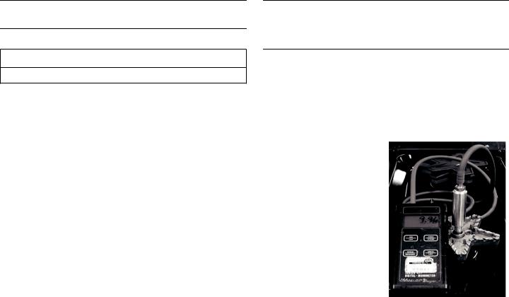
Checking Manifold Pressure (if necessary)
Checking the appliance manifold pressure is NOT REQUIRED for the Propane Gas conversion; however, if the outlet pressure of the gas regulator or the inlet pressure to the appliance is suspect, the following procedure can be used to check the manifold pressure.
1.Attach a portable or hand-held manometer, that reads pressure in inches water column (WC), using a piece of PVC or vinyl tubing.
2.Turn on the electrical and gas supplies to the appliance.
3.Turn one of the cooktop burners to HI position. This is important to acquire a true pressure reading under gas flow conditions.
4.Turn the manual valve for the burner being monitored to HI position. (Spark ignition noise will be heard coming from this burner.)
•The manifold pressure reading on the manometer should be between 9.50" and 10.50" WC for an appliance regulator converted to LP gas. If the manifold pressure reading is below this range, verify that the regulator has been properly converted for use with LP gas, and that the inlet pressure to the appliance is between 11.0" and 14.0" WC.
Installation Instructions |
English | 8 | |
Check Flame Characteristics
To observe the burner flames, it may be necessary to turn off lights or close window blinds to darken the room for easier viewing of the flame.
1.Test STAR® burner ignition. Push in the burner control knob and turn it to HI. The igniter electrode and spark module will produce a clicking sound. Once the air has been purged from the supply lines, the burner should light within four seconds.
•The flames should be stable, with no excessive noise. The inner cones of the individual flames should be defined and separate from each other. Portions of the flame, along the burner, should not exhibit excessive or continuous indications of “lifting” or “lazy flame”.
NOTE: It is normal for slight yellow tipping of the flames to appear after a few minutes of operation using Propane (LP) Gas. Orange-colored streaks in the flame are produced from burning airborne debris; this is normal during initial start up and should dissipate within a few minutes of operation.
Yellow Flames:
Further adjustment is required.
Yellow Tips on Outer Cones:
Normal for LP Gas
Soft Blue Flames:
Normal for Natural Gas
2.Turn valve to SIM to see that the flame continues to wrap around the burner. Blow out the flame, or use a quick fan motion from a writing tablet or piece of cardboard to extinguish the flame, and then observe the burner’s ability to reignite and wrap around (also called “carry-over”) the burner within several seconds. This flame “carry-over” is essential for proper burner ignition and reignition.
3.Test reignition of the XLO and observe the carry-over of the small simmer flames as the XLO system cycles the burners on and off.
•If the flame performance is not acceptable it may be necessary to readjust the valve screw for a top burner that does not have sufficient carry-over of the flame. Turn the valve screw very slightly counter-clockwise until carry-over of the flame is acceptable. (See Setting Valve Screws for the STAR Burners).
•If the burner flame is uneven, flutters, makes excessive noise, or lifts, some of the slots in the burner base may be blocked with food spillage or other debris. Clogged slots can be cleared using a straightened paper clip, needle, or similar object. Hard-to-remove, encrusted food or debris can sometimes be removed using a steel wool pad or fine wire brush.
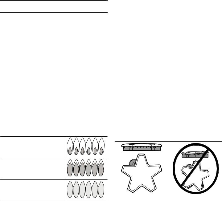
4.Burner flames that are “lazy”, with excessively-long flames, can be created by an incorrectly fitted burner cap—from which many of the outer mantles of the individual flames will tend to “coalesce” or blend together.
Verify that the burner cap is seated properly on its burner base. The cap should fit reasonably flat when correctly-positioned on the base and not rock significantly.


 Star®
Star®


Correct burner cap |
Incorrect burner cap |
|
|
5. Repeat the Ignition and Flame Test procedures for each rangetop burner.
Installation Instructions |
English | 9 | |
 Loading...