


 Loading...
INSTALLATION MANUAL
For Thermador Professional® Cooktops
MANUEL D'INSTALLATION
Des tables de cuisson Thermador Professional®
MANUAL DE INSTALACIÓN
Para Parrillas de Thermador Professional®
Models/
Modèles/
Modelos:
PCG24
PCD24
PCG30
PCG36
PCG48
PCD48

Table of Contents
Safety Instructions . . . . . . . . . . . . . . . . . . . . . . . . . . . .2
Before you Begin . . . . . . . . . . . . . . . . . . . . . . . . . . . . . . . . . . . . . . . . . . . . . . . . . 2
Important Installation Information . . . . . . . . . . . . . . .3
Step 1: Ventilation Requirements . . . . . . . . . . . . . . . . . . . . . . . . . . . . . . . . . . . . . . . . . . . . . . . 3
Step 2: Cabinet Preparation . . . . . . . . . . . . . . . . . . . . . . . . . . . . . . . . . . . . . . . . . . . . . . . . . . . 5 Step 3: Unpacking, Moving, Placing and Anchoring the Cooktop . . . . . . . . . . . . . . . . . . . . . . 10
Step 4: Gas Requirements and Hookup . . . . . . . . . . . . . . . . . . . . . . . . . . . . . . . . . . . . . . . . . 11
Step 5: Electrical Requirements, Connection and Grounding . . . . . . . . . . . . . . . . . . . . . . . . . 12
Step 6: Backguard Installation . . . . . . . . . . . . . . . . . . . . . . . . . . . . . . . . . . . . . . . . . . . . . . . . . 13 Step 7: Burner Test and Adjustment . . . . . . . . . . . . . . . . . . . . . . . . . . . . . . . . . . . . . . . . . . . . 14
Installer Checklist . . . . . . . . . . . . . . . . . . . . . . . . . . . . . . . . . . . . . . . . . . . . . . . 15
To Clean and Protect Exterior Surfaces . . . . . . . . .16
This Thermador Appliance is made by
BSH Home Appliances Corporation
5551 McFadden Ave.
Huntington Beach, CA 92649
Questions?
1-800-735-4328
www.thermador.com
We look forward to hearing from you!
For Massachusetts Installations:
1.Installation must be performed by a qualified or licensed contractor, plumber or gas fitter qualified or licensed by the state, province or region where this appliance is being installed.
2.Shut-off valve must be a “T” handle gas cock.
3.Flexible gas connector must not be longer than 36 inches.
WARNING:
If the information in this manual is not followed exactly, a fire or explosion may result causing property damage, personal injury or death.
--Do not store or use gasoline or other flammable vapors and liquids in the vicinity of this or any other appliance.
--WHAT TO DO IF YOU SMELL GAS
•Do not try to light any appliance.
•Do not touch any electrical switch.
•Do not use any phone in your building.
•Immediately call your gas supplier from a neighbor’s phone. Follow the gas supplier’s instructions.
•If you cannot reach your gas supplier, call the fire department.
--Installation and service must be performed by a qualified installer, service agency or the gas supplier.
English 1
Safety Instructions
Important Safety Instructions
READ AND SAVE THESE INSTRUCTIONS
APPROVED FOR ALL RESIDENTIAL APPLIANCES
FOR RESIDENTIAL USE ONLY
Before you Begin
IMPORTANT: Save these Instructions for the Local Electrical Inspector’s use.
INSTALLER: Please leave these Instructions with this unit for the owner.
OWNER: Please retain these instructions for future reference.
WARNING:
Improper installation, adjustment, alteration, service or maintenance can cause injury or property damage. Refer to this manual. For assistance or additional information consult a qualified installer, service agency, manufacturer (dealer) or the gas supplier.
NOTE:
This Cooktop is NOT designed for installation in manufactured (mobile) homes or for installation in Recreational Park Trailers.
DO NOT install this appliance outdoors.
Data Rating Plate
IMPORTANT: LOCAL CODES VARY. INSTALLATION, ELECTRICAL CONNECTIONS, GAS CONNECTIONS, AND GROUNDING MUST COMPLY WITH ALL APPLICABLE CODES.
Electrical Power Supply
24" Models:
with Wok - 120 VAC, 60 Hz., 1 Ph., 10 Amp circuit with Griddle - 240 VAC, 60 Hz., 1 Ph., 30 Amp circuit 30'' Models:
4 Burners - 120 VAC, 60 Hz., 1 Ph., 10 Amp circuit
36" Models:
6 Burners - 120 VAC, 60 Hz., 1 Ph., 10 Amp circuit with Grill - 120 VAC, 60 Hz., 1 Ph., 10 Amp circuit
with 12" Electric Griddle - 120 VAC, 60 Hz., 1 Ph., 15 Amp circuit
48" Models:
6 Burners with Grill - 120 VAC, 60 Hz., 1 Ph., 10 Amp circuit
6 Burners with 12" Electric Griddle - 120 VAC, 60 Hz., 1 Ph., 15 Amp circuit
4 Burners with 12" Electric Griddle and Grill - 120 VAC, 60 Hz., 1 Ph., 15 Amp circuit
4 Burners with Wok - 120 VAC, 60 Hz., 1 Ph., 10 Amp circuit
4 Burners with 24" Electric Griddle - 240 VAC, 60 Hz., 1 Ph., 30 Amp circuit
Gas Supply
Cooktop Models:
The data rating plate showing the model and serial numbers of your Cooktop or Wok is located on the underside of the Cooktop or Wok chassis near the gas inlet connection and electric power cord. This information is required if customer service is requested. Before installation, the model and serial numbers should be entered in the appropriate spaces in the "BEFORE CALLING FOR SERVICE" section near the back of the Care and Use Manual. After installation accessing the information is difficult.
PLEASE READ ENTIRE INSTRUCTIONS BEFORE PROCEEDING
Natural Gas – 6” min. to 14” max. water column (14.9 mb to 34.9 mb)
Propane Gas – 11”min. to 14”max. water column (27.4 mb to 34.9 mb)
WARNING
Disconnect power before installing. Before turning power ON, be sure that all controls are in the OFF position.
All sealed burners are rated at 15,000 BTU/HR (*13,000 BTU/HR on LP). *All models, except 24” Griddle, are convertible to LP/Propane gas using an accessory conversion kit.
English 2
IMPORTANT |
than 12" clearance, an optional stainless steel Island |
|
• A backguard must be utilized when there is less than a |
Trim is available to cover the backguard mounting |
|
flanges. |
||
12" horizontal clearance between combustible |
||
• Verify that the appliance is correct for the type of gas |
||
materials and the back edge of the cooktop. The |
||
Thermador Low Back backguard must be ordered |
being provided. Refer to “Step 4: Gas Requirements |
|
separately and installed at the rear of the cooktop. For |
and Hookup” on page 11 before proceeding with the |
|
island installations and other installations with more |
installation. |
Important Installation Information
This appliance has been CSA certified for safe operation up to an elevation of 10,200 ft. without any modifications. Exception: For use with Propane, the appliance must be converted per the LP Conversion Instructions.
It is strongly recommended that this appliance be installed in conjunction with a suitable overhead vent hood. (See “Step 1: Ventilation Requirements”.)
Check local building codes for the proper method of appliance installation. Local codes vary. Installation, electrical connections and grounding must comply with all applicable codes. In the absence of local codes the appliance should be installed in accordance with the National Electric Code ANSI Z223.1 current issue and National Gas Code ANSI/NFPA 70 – current issue. In Canada, installation must be in accordance with the CAN 1-B149.1 and .2 – Installation Codes for Gas Burning Appliances and/or local codes.
This appliance is equipped with an intermittent/interrupted ignition device that cycles the two far left surface burners on and off when in the ExtraLow setting.
 CAUTION
(1) When connecting the unit to propane gas, make certain the propane gas tank is equipped
with its own high-pressure regulator in addition to the pressure regulator supplied with this unit. The maximum gas pressure to this appliance is not to exceed 14.0 inches water column (34.9 mb) from the propane gas tank regulator.
(2) This unit is designed as a cooking appliance. Based on safety considerations, never use it for warming or heating a room.
Due to the high heat of the cooktop burners, installing a microwave oven with a ventilation system over the cooktop is not recommended.
This appliance complies with one or more of the following standards:
•UL 858, Standard for the Safety of Household Electric Ranges
•UL 923, Standard for the Safety of Microwave Cooking Appliances
•UL 507, Standard for the Safety of Electric Fans
•ANSI Z21.1 American National Standard for Household Cooking Gas Appliances
•CAN/CSA-C22.2 No. 113-M1984 Fans and Ventilators
•CAN/CSA-C22.2 No. 61-M89 Household Cooking Ranges
CAUTION
To eliminate risk of burns or fire caused by reaching over heated surface units, cabinet storage located above the surface units should be avoided.
It is the responsibility of the owner and the installer to determine if additional requirements and/or standards apply to specific installations.
Remove all tape and packaging before using the appliance. Destroy the packaging after unpacking the appliance. Never allow children to play with packaging material.
Step 1: Ventilation Requirements
It is strongly recommended that a suitable exhaust hood be installed above the appliance. Downdraft ventilation should not be used. The following table indicates the ventilation hood options and blower capacity guidelines that are recommended for use with all Thermador cooktops.
Due to the high heat capability of this unit, particular attention should be paid to the hood and duct work installation to assure it meets local building codes.
Do not install a microwave oven/ ventilator combination above the cooktop, as these types of units do not provide
English 3

the proper ventilation and are not suitable for use with the cooktop.
Select Hood and Blower Models:
•For wall installations the hood width must, at a minimum, equal the nominal width of the appliance cooking surface. Where space permits, a hood larger in width than the cooking surface may be desirable for improved ventilation performance.
•For island installations the hood width should, at a minimum, overhang the appliance cooking surface by 3" on each side.
Hood Placement:
•For best smoke elimination, the lower edge of the hood should be installed 30" above the appliance cooking surface. (See Figure 1).
•If the hood contains any combustible materials (i.e., a wood covering), it must be 36"or greater distance above the cooking surface.
NOTICE:
Most hoods contain combustible components which must be considered when planning the installation.
Consider Make-Up Air:
•Due to the high volume of ventilation air, a source of outside replacement air is recommended. This is particularly important for tightly sealed and insulated homes.
•A qualified heating and ventilating contractor should be consulted.
NOTE:
Ventilation hoods and blowers are designed for use with single-wall ducting. Some local building codes may require double-wall ducting. Before starting installation, consult local building codes and agencies to insure that the installation will meet local requirements.
Cooktop |
Cooktop |
Minimum Recommended |
Ventilation Options |
|
Width |
Configuration |
Blower Capacity* |
||
|
||||
|
|
|
|
|
|
|
|
|
|
|
|
|
30” Pro Wall Hood |
|
24” |
24” griddle -or-24” wok |
600 CFM |
30” Custom Insert w/ optional blower |
|
|
|
|
42” Island Hood w/ optional blower |
|
|
|
|
|
|
|
|
|
30” or 36” Pro Wall Hood |
|
30” |
4 burners |
600 CFM |
30” or 36” Custom Insert w/ optional blower |
|
|
|
|
42” Island Hood w/ optional blower |
|
|
|
|
|
|
|
4 burners w/ grill -or- |
800 CFM |
36” or 42” Pro Wall Hood |
|
36” |
griddle |
36” Custom Insert w/ optional blower |
||
|
||||
|
6 burners |
900 CFM |
42” or 48” Island Hood w/ optional blower |
|
|
|
|
|
|
|
4 burners w/ grill-griddle |
|
48” or 54” Pro Wall Hood |
|
|
combo |
1000 CFM |
48” Custom Insert w/ optional blower |
|
48” |
24” griddle or wok |
|
54” Island Hood w/ optional blower |
|
|
6 burners w/ grill -or- |
1100 CFM |
|
|
|
griddle |
|
||
|
|
|
||
|
|
|
|
|
Important Notes: |
|
|
||
•It is recommended that a Thermador Professional wall or island hood or custom insert is used with Thermador Professional Cooktops.
•Refer to www.Thermador.com for a complete selection of Professional Ventilation options, Blowers, and Accessories.
•* For high output gas cooktops (60,000 BTU or greater), the minimum of one (1) CFM of ventilation per 100 BTU is recommended. If the cooktop has a grill or griddle, add 200 CFM to the estimated blower capacity. Add 400 CFM if the cooktop has a 24” griddle or wok. Additional blower capacity may be required for longer duct runs.
•For island applications, it is recommended to use a hood width that exceeds the width of the cooktop by 6” (overlapping the cooktop by 3” on each end).
•CFM = “cubic feet per minute” (standard blower capacity rating).
English 4
Step 2: Cabinet Preparation
1.To ensure professional results, the cabinet and countertop openings should be prepared by a qualified cabinet worker.
2.The clearances shown in Figure 1 are required. The same clearances apply to island installations, except for the overhead cabinets, which must have a space wide enough to accept the island hood.
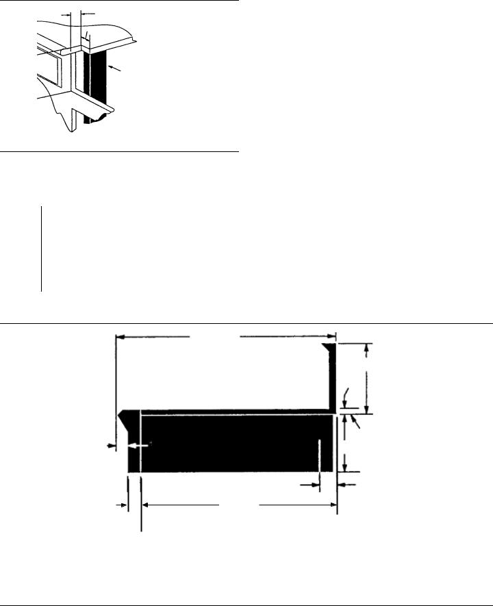
3.The cooktop is designed to hang from the countertop by its side flanges. The countertop however, must be strong enough to support this cooktop. It may be necessary to add a supporting cleat along each side (see Figure 2) or a 2 x 4 corner brace (see Figure 3 and Figure 4 and Detail A). Another alternative would be to construct a deck to set the cooktop on.
4.The cooktop can be installed in various positions with the front either flush or projecting, depending on the countertop’s depth. (See Figure 5, side view of cooktop; see Figure 3, Figure 4, Figure 6 and Figure 7 for alternate mounting positions.)
5.The gas and electrical supply must be located in an area that is accessible without requiring removal of the cooktop. The appliance electrical power cord and gas pipe connection are located on the left rear underside of the cooktop (except on models with a 24" griddle where power cord is located in the center), as shown in Figure 5 and Figure 9.
6.The maximum depth of over head cabinets installed on either side of the hood is 13".
A 36-inch minimum clearance is required between the cooking surface of the cooktop and the bottom of an unprotected cabinet. A 30-inch distance can be used when the bottom of the wood or metal cabinet is protected by not less than 1/4 inch of a flame retardant material covered with not less than No. 28 MSG sheet steel, 0.015 inch (0.4 mm) thick stainless steel, 0.024 inch (0.6 mm) aluminum, or 0.020inch (0.5 mm) thick copper. Flame retardant materials bear the mark:
UNDERWRITERS LABORATORIES INC. CLASSIFIED MINERAL AND FIBER BOARDS SURFACE BURNING CHARACTERISTICS
followed by the flame spread and smoke ratings. These designations are shown as "FHC (FIame Spread/Smoke Developed)." Materials with "O" flame spread ratings are flame retardant. Local codes may allow other flame spread ratings.
7. When there is less than a 12" horizontal clearance between combustible material and the back edge of the cooktop above the cooking surface, a Thermador Low Backguard must be installed. (See Step 6). When
clearance to combustible material is over 12", a Thermador Island Trim may be used. Attach the backguard before sliding the appliance into the final installed position.
8.Establish the centerline of the cooktop’s desired location. It should be the same as the center of the overhead ventilation hood.
9.Cut the openings for the following installations:
•Wall installation, see Figure 3.
•Island installation, see Figure 4.
10.For models with a 24” griddle, attach the foam strip to countertop centered along the rear about 1/16” from the edge.
11.For installation of a 48" cooktop above two side-by-side Thermador Warming Drawers, Model No. WD24, refer to Figure 8. Completing the installation as per Figure 8 will result in the left and right edges of the cooktop being aligned with the left edge of the left-side warming drawer and right edge of the right-side warming drawer. If different alignment is desired, the 1-7/8" horizontal distance between warming drawer cutouts may be varied. However, maintain at least a 1-1/8" distance to avoid interference between the warming drawers. Attach a 90-degree elbow to the gas cooktop inlet pipe. All above-the-countertop clearances must be maintained, as shown in Figure 1.
As defined in the "National Fuel Gas Code" (ANSI Z223.1/NFPA54-current issue).
NOTES:
•If a solid side cabinet wall exists on one or both sides, you will need to notch the front corner of the cabinet to match the countertop notch and to allow clearance for the cooktop front (see Detail A, Figure 3 and Figure 4).
•If a supporting deck is used, the sides or bottom of the cutout may be solid combustible or non-combustible material. If the bottom is solid, provide a 8" by 8" cutout in the left rear corner of the supporting deck. This will provide clearance for the gas inlet and power cord, while also allowing viewing of the product rating label.
•On models which have a 24" griddle with power cord in the center, provide 2 (two) separate pieces of supporting deck to allow clearance in center for cord to pass through.
•Always keep appliance area clean and free from combustible materials, gasoline and other flammable vapors and liquids.
•Do not obstruct the flow of combustion and ventilation air to the unit.
English 5

30" to 36" Wide Hood for 24" Wok or 24" Griddle 30" to 36" Wide Hood for 30" Cooktop
36" to 42" Wide Hood for 36" Cooktop
48" to 60" Wide Hood for 48" Cooktop
Combustible
Material 
VENT HOOD
|
|
|
30" |
Min. from bottom of |
|
|
|
|
|
|
|
|
|
|
||||||
|
|
|
|
Overhead Hood to Cooking |
|
|
|
|
|
|
|
|
|
|
||||||
|
|
|
|
Surface (36" or greater if |
|
|
|
|
|
|
|
|
|
|
||||||
|
|
|
|
hood contains combustible |
|
|
|
|
|
|
|
|
|
|
|
|
||||
|
|
|
|
|
|
|
|
|
|
|
|
|
|
|
||||||
|
|
|
|
|
|
|
|
|
|
|
|
|
|
|
|
|||||
|
13" Max. |
|
|
materials ). |
|
|
|
|
|
Horizontal |
36" Min. to |
|||||||||
|
depth of |
|
|
|
|
|
|
|
|
|
|
|
|
Min. |
|
Clearance |
Combustible |
|||
|
|
|
|
|
|
|
|
|
|
|
|
|||||||||
|
|
|
|
|
|
|
|
|
|
|
|
|
|
|||||||
|
overhead |
|
|
|
|
|
|
|
|
|
|
|
|
|
|
|
|
|
Material |
|
|
|
|
|
|
|
|
|
|
|
|
|
|
|
|
|
|
||||
|
|
|
|
|
|
|
|
|
|
|
|
to Rear Wall: |
||||||||
|
|
|
|
|
|
|
|
|
|
|
|
|||||||||
|
|
|
|
|
|
|
|
|
|
|
|
|
||||||||
|
cabinets |
|
|
|
|
|
|
|
|
|
|
|
|
|||||||
|
|
|
|
|
|
|
|
|
|
|
|
|
0" with Backguard |
from Cooking |
||||||
|
18" Min |
|
|
|
|
|
|
|
|
|
|
|
|
12" with Island Trim |
Surface. |
|||||
|
|
|
|
|
|
|
|
|
|
|
|
|
|
|
|
|
|
|
|
|
|
3" min. |
|
|
|
|
|
|
|
|
|
|
|
|
|
|
|
|
|
|
|
|
|
|
|
|
|
|
|
|
|
|
|
|
|
|
|
|
|
|
||
|
|
|
|
|
|
|
|
|
|
|
|
|
|
|
|
|
|
|
||
|
|
|
|
|
|
|
|
|
|
|
Cooking Surface |
|
|
|||||||
. |
both sides |
|
|
|
|
|
|
|
|
|
|
|
|
|||||||
|
|
|
|
|
|
|
|
|
|
|||||||||||
|
|
|
|
|
|
|
|
|
|
|
|
|
|
|
|
|
|
|||
|
|
|
|
|
|
|
|
|
|
|
|
|
|
|
|
|
|
|||
"A"
0" Sides
0" Bottom
Figure 1: Clearance Requirements
English 6
B
D
See Detail A
B
23-5/16”
Counter Sunk Screws
Figure 2: Installing Side Supports (both sides) |
Figure 3: Wall Installation with Countertop Backsplash |
|
|
Vent Hood Width Requirements
Island – 42" or 48" Wide Hood for 24" Wok or Griddle Island – 42" or 48" Wide Hood for 36" Cooktop Island – 54" or 60" Wide Hood for 48" Cooktop
See Detail A |
D |
3/4” Min. |
22-13/16”
Figure 4: Island Installation (No Countertop Backsplash)
English 7
C
B
7-11/16”
2 x 4 Corner
Support
Corner Notch Detail
Detail A: (Front Face of Cabinet)
|
24” Wok/Griddle |
30” Cooktop |
36” Cooktop |
48” Cooktop |
|
|
|
|
|
A |
24-3/4” |
29-7/8” |
35-7/8” |
47-7/8” |
|
|
|
|
|
B |
3/8” |
3/8” |
3/8” |
13/16” |
|
|
|
|
|
C0” (Control Panel Projecting 1-1/4” from Base Cabinet Face)
11/16” (Notch Required for Standard 24” - Deep Base Cabinet, Control Panel Projecting 9/16” from Base Cabinet Face) 1-1/4” (Control Panel Flush to Cabinet Face - Min. 24-9/16” - Deep Base Cabinet Required)
D |
24” |
29-1/8” |
35-1/8” |
46-1/4” |
|
|
|
|
|
25-3/8”
12”
1/2”
Side
Flange 7-5/8”
5-1/4” TO CENTERLINE OF
GAS INLET
23-5/16”
1-1/4”  Cabinet face for installation with projecting control panel
 Cabinet face for installation with flush control panel
* Low Back required when there is less than 12” horizontal clearance from back of cooktop to combustible material. With more than 12” of clearance, the Island Trim may be used.
Figure 5: Side View of Cooktop
English 8
11/16” Notch
Depth
9/16”
Front projects outward 9/16" as shown from standard 24"-deep base.
Figure 6: Projecting from Cabinet Front
Minimum 3/4" (19 mm)
-13/16" |
||
22 |
9 |
cm) |
(57, |
|
|
|
|
|
(22,9cm) 9"
|
|
|
|
13/16" |
||
-1/4" |
|
|
(21 |
mm) |
||
|
|
|
||||
|
|
|
|
|||
46 |
cm) |
|
|
|
|
|
(117,5 |
|
|
|
0" to |
||
|
-11/16" |
|
|
|||
|
|
|
|
|||
7 |
cm) |
|
|
1-1/4" |
||
|
(19,52 |
|
|
|
||
|
|
|
(0-32mm) |
|||
|
|
|
|
|||
|
|
WD24 |
SeeFig.4 |
|||
|
|
andTable |
||||
WD24 |
Cutout |
|||||
|
|
DimensionC |
||||
Cutout |
-1/2" |
|||||
|
|
|||||
|
|
22 |
cm) |
|
||
|
|
(57,2 |
|
|||
|
|
|
|
|
||
1-7/8" (4,8 cm) Horizontal Distance Between Cutouts
2-3/4" (7 cm) Vertical Distance Between Cutouts
(See Side View for Wood Support)
Figure 8a: Installation of 48” Cooktop above two side-by- side Thermador Warming Drawers - Model No. WD24
Notch
REAR
|
|
7-11/16” |
|
|
|
Plywood support |
|
(19,52 cm) |
|
||
|
|
|
|
|
|
|
|
|
|
|
|
|
2-3/4" (70 mm) |
||
|
|
|
||||
|
|
|
|
|
|
minimum |
|
|
|
|
|
|
|
Install additional |
|
|
|
|
between |
|
|
|
|
||||
|
|
|
|
cutouts |
||
wood support along |
|
|
|
|
||
|
|
|
|
|
||
front edge of cutout |
|
|
|
|
|
|
Front flush with cabinets; minimum of 24-9/16" cabinet depth required.
Figure 7: Flush to Cabinet Front
Figure 8b: Installation of 48” Cooktop above two side-by-side Thermador Warming Drawers - Model No. WD24 (Side View)
English 9
Product Rating
Label/Serial Tag
Threading compounds must be
resistant to Propane Gas
P24WOK 1/2" NPT
3/4” flex line
3” Min.
Power
Cord or  gas flow Conduit
3-Prong grounding type receptacle connected to a properly grounded and polarized electrical supply rated at 120VAC, 10 Amps, (or 15A*) Single Phase, 60 HZ. NOTE: This is not applicable to 240 VAC models with 24" electric griddle.**
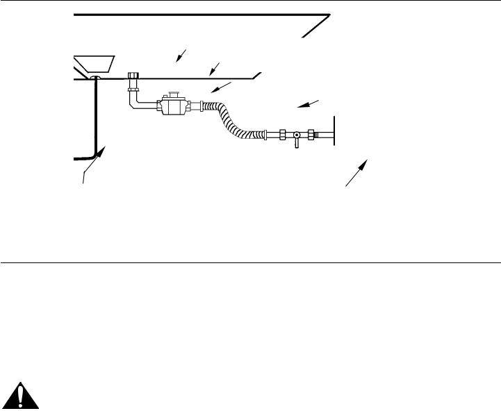
A manual valve must be installed external to the appliance, in an accessible location from the front, for the purpose of shutting off the gas supply.
Figure 9: Front - Bottom of Unit
All Installer supplied parts must conform to Local Codes.
*15 Amp 120 VAC electrical supply is required for 36" and 48" models with a 24" electric griddle. **30 Amp 240 VAC electrical supply is required for models with a 24" electric griddle.
Step 3: Unpacking, Moving, Placing and
Anchoring the Cooktop
CAUTION
Proper equipment and adequate manpower must be used in moving the appliance to avoid damage and/or personal injury. The unit is heavy and should be handled accordingly.
Important
•Verify that the appliance is correct for the type of gas being provided. Refer to Step 4 before proceeding with the installation.
•Attach the backguard before sliding the appliance into the final installed position. See Step 6.
1.Remove the outer carton and packing material from the shipping base. Ensure that you have all cooktop components before proceeding.
2.Remove the top grate castings, burner caps and grill grate (if so equipped) to reduce unit weight.
NOTE:
Leave adhesive-backed foam layer over brushed-metal surfaces, to protect finish from scratches, until the cooktop is installed in its final position.
3.Lift and place the cooktop in the opening. Be careful not to pinch the power cord or gas inlet. Care should be used not to scratch the griddle cooking plate.
4.Make sure that the power cord is free and hanging loose.
5.The cooktop must be level for proper performance.
6.The grill frame (if so equipped) has been leveled during assembly so do not attempt to level the grill.
7.Replace the cooking grates, burner caps and grill plate (if so equipped). Ensure that the burner caps are correctly seated on the burner bases.
English 10

Grill/Griddle Tilt Adjustment (not all models)
Check the grill or griddle adjustment by pouring two tablespoons of water on the back of the grill or griddle plate. The water should slowly roll into the grease tray. If not, adjust the two screws under the back of the plate. Start with one half turn counter-clockwise (CCW) of the screws. Further adjustment should be made by one-quarter turn until water slowly flows into the grease tray.
Step 4: Gas Requirements and Hookup
Cooktops are shipped by the factory to operate on natural gas.They must be converted for use with propane. Verify the type of gas being used at the installation site matches the type of gas used by the appliance. If the location/job site requires conversion from natural gas to propane (LP), contact the dealer where the unit was purchased or contact Thermador. The field conversion kit for the Professional Cooktops in this series is Thermador Model PLPKIT. Obey all instructions in PLPKIT for correct conversion of the gas regulator and settings for the gas valves. Field conversion must be done by qualified service personnel only.
This appliance has been CSA certified for safe operation up to an elevation of 10,200 ft. without any modifications. Exception: For use with propane, the appliance must be converted per the LP conversion instructions. Please refer to the LP Conversion Instructions for further information.
Natural Gas Requirements:
Inlet Connection: 1/2” NPT (min. 3/4” dia. flex line)
Supply Pressure: 6” min. to 14” max. water column (14.9 to 34.9 mb)
Manifold Pressure: 5” water column (12.5 mb)
Propane Gas Requirements:
Inlet Connection: 1/2” NPT (min. 3/4” dia. flex line) Supply Pressure: 11” min. to 14” max. water column (27.4 mb to 34.9 mb)
Manifold Pressure: 10” water column (24.9 mb)
WARNING
If a gas conversion kit is used, the kit shall be installed by a qualified service agency in accordance with the manufacturer’s instructions and all applicable codes and requirements of the authority having jurisdiction. If the information in the instructions is not followed exactly, a fire, explosion or production of carbon monoxide may result causing property damage, personal injury or loss of life. The qualified service agency is responsible for the proper installation of the kit. The installation is not proper and complete until the operation of the converted appliance is checked as specified in the manufacturer’s instructions supplied with the kit.
Hook Up
•A manual gas shut-off valve must be installed external to the appliance, in a location accessible from the front, for the purpose of shutting off the gas supply. The supply line must not interfere with the back of the unit. Make sure the gas supply is turned off at the manual shut-off valve before connecting the appliance.
•The installer should inform the consumer of the location of the gas shut-off valve. Make sure all users know where and how to shut off the gas supply to the cooktop.
•The gas supply connections shall be made by a competent technician and in accordance with local codes or ordinances. In the absence of local codes, the installation must conform to the National Fuel Gas Code ANSI Z223.1/NFPA54-current issue.
•Always use pipe-sealing compound or Teflon® tape on the pipe threads, and be careful not to apply excessive pressure when tightening the fittings.
•Leak testing of the appliance shall be in accordance with the following instructions.
•Turn on gas and check supply line connections for leaks using a soap and water solution.
•Bubbles forming indicate a gas leak. Repair all leaks immediately after finding them.
•Do not use a flame of any kind to check for gas leaks.
•All installer-supplied parts must conform to applicable codes.
CAUTION
When connecting unit to propane gas, make certain the propane gas tank is equipped with its own high pressure regulator in addition to the pressure regulator supplied with the appliance. The pressure of the gas supplied to the appliance regulator must not exceed a 14” water column (34.9 mb).
English 11

 CAUTION
The appliance must be isolated from the gas supply piping system by closing its individual manual shut-off valve during any pressure testing of the gas supply piping system at test pressures equal to or less than 1/2 psig (3.5kPa).
The appliance and its individual shut off valve must be disconnected from the gas supply piping system during any pressure testing of the system at test pressures in excess of 1/2 psig (3.5kPa.).
When checking the manifold gas pressure, the inlet pressure to the regulator should be at least 6.0" W.C. for natural gas or 11.0" for propane.
Do not attempt any adjustment of the pressure regulator.
Step 5: Electrical Requirements,
Connection and Grounding
CAUTION
Improper grounding or reverse polarization will cause malfunction (such as continuous sparking of the burner igniters). This can damage the appliance and can create a condition of shock hazard. If the circuit is not correctly grounded and polarized, it is the responsibility and obligation of the installer and user to have the existing receptacle changed to a properly grounded and polarized receptacle. This must be accomplished in accordance with all applicable local codes and ordinances by a qualified electrician. In the absence of local codes and ordinances, the receptacle replacement shall be in accordance with the National Electric Code. (See Figure 10.)
•Before installing, turn power OFF at the service panel. Lock service panel to prevent power from being turned ON accidentally.
•Always disconnect appliance from the electric supply either by disconnecting power cord or shutting off the breaker before servicing the appliance.
•Before you plug in an electrical cord, be sure all controls are in the OFF position.
•All 120 Volt cooktop models must be plugged into a mating 3-Prong, Grounding-Type Receptacle. The receptacle must be connected to a properly grounded and polarized electrical power supply rated at 120VAC, Single Phase, 60HZ. See “Electrical Power Supply Over-current Protection Requirements” on page 13 on this page for proper over-current protection requirements for each model.
English 12
•All 240 Volt cooktop models require hard wire connections.
•Observe all governing codes and ordinances when grounding. In the absence of these codes or ordinances observe National Electrical Code ANSI/ NFPA No. 70 current issue. See Figure 10 for recommended grounding method.
•An electrical wiring diagram and schematic have been attached to the bottom of the cooktop chassis for access by a qualified service technician. Do not remove or discard this important information.
Grounding Method for 120 VAC Models
The cooktop is factory equipped with a power supply cord with a three-prong grounding plug (with polarized parallel blades).
IT MUST BE PLUGGED INTO A MATING, GROUNDING TYPE RECEPTACLE THAT IS CONNECTED TO A CORRECTLY POLARIZED 120 VOLT CIRCUIT (240 VOLT CIRCUIT FOR MODELS WITH 24" ELECTRIC GRIDDLE. (See Figure 10).
Figure 10: Recommended Grounding Method for 120V Models
THE THIRD, GROUND PRONG MUST NOT BE CUT OR REMOVED UNDER ANY CIRCUMSTANCES.
Electrical Connection for 240 VAC Models
1.Attach flexible conduit to the junction box.
2.Connect the cooktop lead wires to the junction box supply wires in proper phase:
For all 240 VAC models, connect black (L1) to black, red (L2) to red, white wire to neutral and green wire to ground.

NOTE:
If the 120V cooktop is installed and connected as specified above, it will be completely grounded in compliance with the National Electric Code.
3.Turn on power supply.
4.Test operation.
Cooktop with a wok - 10 Amp circuit protection
Cooktop with a 24" electric griddle - 30 Amp circuit protection 240 VAC.
Installer - show the owner the location of the circuit breaker or fuse. Mark it for easy reference.
Conduit (Approx. 3”)
12” APPROXIMATE
 “J” Box
Figure 11: Junction Box Location
Electrical Power Supply Over-current Protection
Requirements
4 Burners - 10 Amp circuit protection
6 Burners - 10 Amp circuit protection
4 Burners with a grill - 10 Amp circuit protection
4 Burners with a 12" electric griddle - 15 Amp circuit protection
6 Burners with a grill - 10 Amp circuit protection
6 Burners with a 12" electric griddle -15 Amp circuit protection
4 Burners with a grill and a 12" electric griddle - 15 Amp circuit protection
4 Burners with a wok10 Amp circuit protection
4 Burners with a 24" electric griddle -30 Amp circuit protection, 240VAC
Step 6: Backguard Installation
A Low Back backguard must be installed when there is less than a 12" clearance between combustible materials and back edge of cooktop. (See Figure 1 and Figure 5.) For island installations and other installations with over 12" clearance, an optional stainless steel trim channel is
available to cover the backguard mounting flanges. Attach the backguard before sliding the appliance into the final installed position. Follow Steps A through C below:
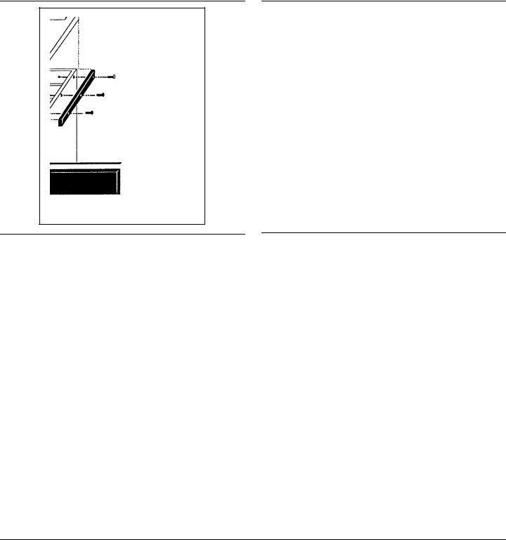
1.Slide backguard over the two flanges on the rear of the appliance. Fasten the front and back with the two screws (see A, Figure 12) provided.
2.Fasten the top of the backguard to the wall with two screws through the backguard. (See B, Figure 12.)
3.Place the backguard cap on top and fasten using the two counter-sink screws provided. (See C, Figure 12.)
C
B
A
Figure 12: Low Back Attachment
English 13
Low Back and Island Trim Model Numbers
Cooktop Size/Type |
12” Low Back |
Island Trim* |
|
|
|
24” Griddle |
PC24LB |
PC24IT |
24” Wok |
GP24LBS |
GP24ITS |
30” |
PC30LB |
PC30IT |
36” |
GPS36LBS |
GPS36ITS |
48” |
GPS48LBS |
GPS48ITS |
|
|
|
*Requires a minimum of 12” horizontal clearance between back of appliance and combustible materials.
Step 7: Burner Test and Adjustment
Install any loose components, such as burner caps and grates that may have been removed earlier.
Be certain that burner caps seat properly into the burner bases. Before testing operation of the appliance, verify that the unit and the gas supply have been carefully checked for leaks and that the unit has been connected to the electrical power supply. Turn the manual gas shut-off valve to the open position.
Test Cooktop Burners
Test Burner Ignition. Select a cooktop burner knob. Push in and turn counterclockwise to HI. The ignitor/spark module will produce a clicking sound. Once the air has been purged from the supply lines, the burner should light within four (4) seconds.
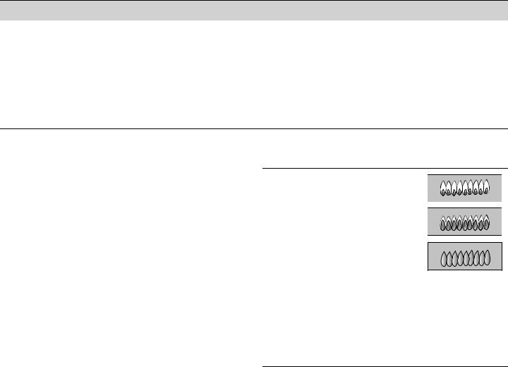
Test Flame: High Setting. Turn burner on to HI. See Figure 13 for appropriate flame characteristics. If any of the cooktop burners continue to burn mostly or completely yellow, verify that the burner cap is positioned properly on the burner base, then re-test. If flame characteristics do not improve, call Thermador.
Test Flame: Low Setting. Turn burner on to LO. Verify that the flame completely surrounds the burner. There should be a flame at each burner port and there should be no air gap between the flame and the burner. If any burners do not carry over, call Thermador.
The two far left burners feature XLO, causing the flame to cycle on and off when the knob is set to the XLO range. This is normal operation.
Repeat the Ignition and Flame Test procedures described above for each cooktop burner and the grill burner (if so equipped).
Yellow Flames:
Further adjustment is required.
Yellow Tips on Outer Cones:
Normal for LP Gas.
Soft Blue Flames:
Normal for Natural Gas.
If the flame is completely or mostly yellow, verify that the regulator is set for the correct fuel. After adjustment, retest.
Some orange-colored streaking is normal during the initial start-up.
Allow unit to operate 4-5 minutes and re-evaluate before making adjustments.
Figure 13: Flame Characteristics
WHEN FLAME IS PROPERLY ADJUSTED:
•There should be a flame at each burner port.
•There should be no air gap between the flame and burner port.
The gas grill uses a tube-style burner that has an air shutter which allows adjustment to the amount of primary air inside the burner tube.
Air shutters of tube-style burners are pre-adjusted at the factory, and usually do not require readjustment except under rare conditions such as installation at high altitude.
If grill burner/flame adjustment is required, go to the procedure: “Flame Adjustment (if necessary)”.
English 14

Flame Adjustment (if necessary)
Tube-style gas burners used in Thermador appliances have air shutter systems which are similar to the illustration in Figure 14, and can be adjusted using the following method (unless adjustment is not recommended). It is necessary to remove the burner from the appliance in order to perform air-shutter adjustments.
•Loosen shutter screw(s) and turn shutter to new position.
•Adjust the shutter to more-closed position if the flame is lifting or blowing, or is not carrying over.
•Adjust the shutter to more-open position if the flame is too yellow. (See Figure 14.)
•Retighten the shutter screw(s).
•After adjustment, reinstall the burner and perform flame evaluation. The air shutter must fit over the orifice hood for proper operation of the burner.
•Repeat procedure as needed until flame characteristics are acceptable. (See Figure 13.)
Screw
More Open: |
Air |
Shutter |
|
Less Yellow Flame |
|
More Closed: |
|
Less Blue Flame |
|
More Carryover |
|
Less Lifting or Blowing |
|
Figure 14: Air Shutter Adjustment (if necessary)
 WARNING
Burner adjustments must be performed by a qualified technician. Improper adjustments may cause harmful by-products or void the appliance’s warranty.
Allow burners to cool before attempting to remove them!
Call Thermador if:
1.Any of the burners do not light.
2.Any of the burners continue to burn yellow.
Installer Checklist
Final Check List
•Cooktop correctly positioned in countertop recess.
•Specified clearances maintained to cabinet surfaces.
•Burner caps positioned properly on burner bases.
•All packaging material removed. (NOTE: Wok models have tie-down straps around the burner, which must be removed before using the appliance.)
•Island Trim or Backguard attached according to instructions.
•The griddle/ grill plate tilted slightly forward. (See “Grill/ Griddle Tilt Adjustment (not all models)” on page 11.)
Gas Supply
•Connection: 1/2" NPT with a minimum 3/4" diameter flex line.
•If converting from natural to LP gas, refer to LP Conversion Instructions for details.
•Manual gas shut off valve installed in an accessible location (without requiring removal of appliance).
•Unit tested and free of gas leaks.
Electrical
•For models with the 12" electric griddle, a polarized and grounded 120VAC receptacle with 15 AMP over current protection is provided for service cord connection.
•For models with the 24" electric griddle, a properly grounded, 240 VAC service connection with 30 AMP over current protection is provided.
Operation
•All internal packing materials removed. (Check below grates and grill pans.)
•Bezels centered on burner knobs, and knobs turn freely.
•Purge air from gas system by operating one of the top burners for several minutes.
•Each burner lights satisfactorily, both individually and with other burners operating.
•Burner grates are correctly positioned.
Installer
•Give CARE and USE MANUAL and INSTALLATION INSTRUCTIONS to your customer.
English 15
Loading...