


 Loading...
Thermador MED302JP, MEDMC301JS, MED272JS, PODMW301J, PODM301J Installation Guide
...
MASTERPIECE®/THERMADOR PROFESSIONAL® SERIES BUILT-IN OVEN

Built-in oven
Four encastré
Horno empotrado
TABLE OF CONTENTS |
........................... 4 |
Table de Matières................................................ |
19 |
Contenido.............................................................. |
35 |
Models/Modèle/Modelo
ME301JP
ME301JS
ME302JP
ME302JS
MED271JS
MED272JS
MED301JS
MED301JP
MED302JS
MED302JP
MEDMC301JS
MEDMC301JP
MEDMCW71JS
MEDMCW31JP
MEDMCW31JS
POD301J
PODC302J
PODM301J
PODMW301J

Table of ContentsnsoitcuralI |
|
IMPORTANT SAFETY INSTRUCTIONS ......................... |
5 |
Appliance Handling Safety................................................... |
5 |
Safety Codes and Standards .............................................. |
5 |
Electric Safety......................................................................... |
5 |
Related Equipment Safety ................................................... |
5 |
Transport ................................................................................. |
5 |
Preparation...................................................................... |
6 |
Before you Begin ................................................................... |
6 |
Checklist for Installation................................................ |
6 |
Dimensions and Cabinet Requirements....................... |
7 |
Removing Packaging ..................................................... |
7 |
Left Packaging Bracket Removal ....................................... |
7 |
Right Packaging Bracket Removal .................................... |
7 |
Electrical Installation...................................................... |
8 |
Electrical Connection ............................................................ |
8 |
Four-wire Connection............................................................ |
8 |
Three-wire Connection.......................................................... |
9 |
Oven Installation ............................................................ |
9 |
For Best Installation .............................................................. |
9 |
Removing the Oven Door .................................................... |
9 |
Placing the Oven into the Cabinet Opening .................. |
11 |
Replacing the Oven Door .................................................. |
12 |
Combination Units Microwave Trim Adjustment ........... |
12 |
Testing Operation......................................................... |
12 |
Service .......................................................................... |
13 |
Before Calling Service........................................................ |
13 |
Data Plate ............................................................................. |
13 |
Appliance and Cabinet Cutout Dimensions .............. |
13 |
Dimensions for 27” Wall-Mounted Units......................... |
13 |
Dimensions for 27” Under-Counter Units....................... |
15 |
Dimensions for 30” Wall-Mounted Units......................... |
15 |
Dimensions for 30” Under-Counter Units....................... |
17 |
THERMADOR® Support .............................................. |
18 |
Service................................................................................... |
18 |
Parts and Accessories ....................................................... |
18 |
! " #$!! % & " '$(
)# *
-.!!-/01-(0'.
+++, ,
2 3 4 + 5 4 #6
4

9 IMPORTANT SAFETY INSTRUCTIONS
READ AND SAVE THESE INSTRUCTIONS
N IE S EY HT TE F E A V S A S T N D AN TA R OD PA ME IR
WARNING
If the information in this manual is not followed exactly, fire or shock may result causing property damage or personal injury.
WARNING
Do not repair, replace or remove any part of the appliance unless specifically recommended in the manuals. Improper installation, service or maintenance can cause injury or property damage. Refer to this manual for guidance. All other servicing should be done by a qualified technician.
Appliance Handling Safety
Unit is heavy and requires at least two people or proper equipment to move.
Do not lift appliance by door handle.
Hidden surfaces may have sharp edges. Use caution when reaching behind or under appliance.
Safety Codes and Standards
This appliance complies with the latest version of one or more of the following standards:
CAN/CSA C22.2 No. 61 - Household Cooking Ranges
UL 858 - Household Electric Ranges
CAN/CSA C22.2 No. 150 - Microwave Ovens
UL 923 - Microwave Cooking Appliances
CSA C22.2 No. 64 - Household Cooking and LiquidHeating Appliances
UL 1026 - Electric Household Cooking and Food Serving Appliances
It is the responsibility of the owner and the installer to determine if additional requirements and/or standards apply to specific installations.
Electric Safety
Before you plug in an electrical cord, be sure all controls are in the OFF position.
If required by the National Electrical Code (or Canadian Electrical Code), this appliance must be installed on a separate branch circuit.
Installer - show the owner the location of the circuit breaker or fuse. Mark it for easy reference.
Important - save these instructions for the local electrical inspector’s use..
Before installing, turn power OFF at the service panel. Lock service panel to prevent power from being turned ON accidentally.
Refer to data plate for more information. See “Data Plate” under “Service” for data plate location.
Be sure your appliance is properly installed and grounded by a qualified technician. Installation, electrical connections and grounding must comply with all applicable codes.
Related Equipment Safety
Remove all tape and packaging before using the appliance. Destroy the packaging after unpacking the appliance. Never allow children to play with packaging material
Never modify or alter the construction of the appliance. For example, do not remove leveling legs, panels, wire covers or anti-tip brackets/screws.
Transport
To avoid damage to the oven vent, use the transport method shown in the picture below.
5
Preparation
Before you Begin
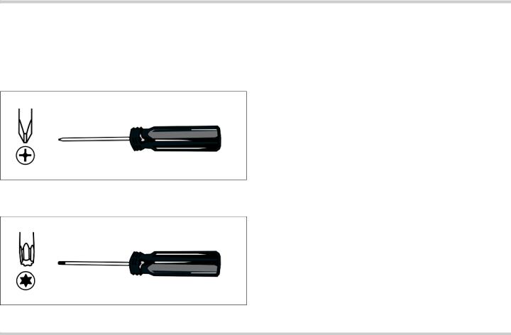
Tools and Parts Needed
#2 Philips head screwdriver (to install trim screws).
T20 Star-head screwdriver (to remove shipping screws).
1/8” drill bit and drill (to drill pilot holes for trim screws).
Measuring tape.
Gloves and long sleeves are recommended (to help protect hands and arms from scratches).
Parts Included
Phillips head screws (6).
Power Requirements
The outlet must be properly grounded in accordance with all applicable codes.
Checklist for Installation
Use this checklist to verify that you have completed each step of the installation process. This can help you avoid common mistakes.
Refer to detailed instructions for each step in the sections following this checklist.
1.Before installing the oven, be sure to verify the cabinet dimensions are correct for your unit and that the required electrical connections are present. Make sure the electrical conduit provided on the unit is able to reach to the point of connection.
Section: Dimensions and Cabinet Requirements
2.Move the oven unit into place in front of the cabinet opening.
Section: Removing Packaging
3.Remove packaging materials, leaving the bottom packaging on the unit to avoid damaging flooring.
Section: Removing Packaging
4.Remove the T20 (star head) screws holding the unit to the base of the carton.
Section: Removing Packaging
5.Remove the oven door(s).
Section: Oven Installation, "Removing the Oven Door"
6.Team lift the unit directly into the cabinet cutout.
Section: Oven Installation, "Placing the Oven into the Cabinet Opening"
7.Slide the unit all the way into place.
Section: Oven Installation, "Placing the Oven into the Cabinet Opening"
8.Fasten the oven unit to the cabinetry opening with the screws supplied.
Section: Oven Installation, "Placing the Oven into the Cabinet Opening"
9.Reinstall the oven door(s).
Section: Oven Installation, "Placing the Oven into the Cabinet Opening"
Always read and follow the complete installation instructions contained in this manual.
6
Dimensions and Cabinet Requirements
Cabinet requirements vary depending on the model to be installed. Please consult the “Cabinet Dimension Requirements” section at the back of this installation manual for the details pertaining to your particular model.
All models require:
¼” (6.4 mm) space between the side of the oven and an adjacent wall or cabinet door when installed at the end of a cabinet run.
Installation of 2x4’s extending front to back flush with the bottom and side of the opening to provide oven support. This supporting base must be well secured to the floor/cabinet and must be level.
The electrical conduit box must be located above the unit to facilitate connecting and servicing the unit.
The cabinet base must be flat and capable of supporting the weight of your oven when in use (varies by model up to 429 lbs. (195 kg)). See the appropriate weight for your model in the “Cabinet Dimension Requirements” section at the back of this installation manual.
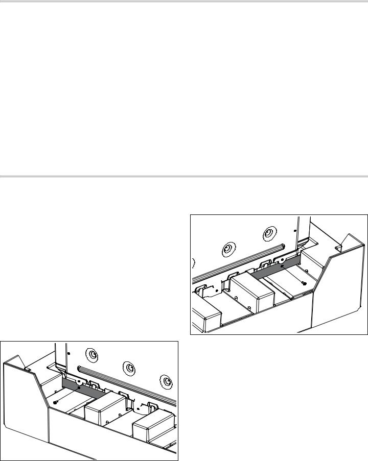
Removing Packaging
NOTICE: To prevent damage to your floor keep the unit Right Packaging Bracket Removal in its packaging base until ready to be placed in the
cabinet opening. Do not slide the unit across the flooring.
Different models use different packaging materials. Actual brackets may look differently. Bracket remains in
packaging base.
1. Cut straps on outside of box.
2. Remove cardboard box.
3. Remove all top and side cardboard and Styrofoam
braces.
4. Place oven in front of cabinets where it is to be installed.
5. Unscrew unit from Left and Right Brackets as show in “Left and Right Packaging Bracket Removal“.
Left Packaging Bracket Removal
7

Electrical Installation
All model ovens on the front cover are dual rated, designed to be connected to either 208/240V AC, 60 Hz, 4 wire, single-phase power supply.
Model |
Circuit Required |
|
|
|
|
ME301JP, |
|
|
ME301JS, |
|
|
MED271JS, |
30 AMP |
|
MED301JS, |
||
|
||
MED301JP, |
|
|
POD301J |
|
|
|
|
|
ME302JP, |
|
|
ME302JS, |
40 AMP |
|
MED272JS, |
||
MED302JS, |
|
|
MED302JP, |
|
|
PODC302J |
|
|
|
|
|
MEDMC301JS, |
|
|
MEDMC301JP, |
|
|
MEDMCW71JS, |
|
|
MEDMCW31JP, |
50 AMP |
|
MEDMCW31JS, |
|
|
PODM301J, |
|
|
PODMW301J |
|
|
|
|
The electrical supply should be a 4-wire single-phase AC. Install a suitable conduit box (not furnished). An appropriately-sized, UL-listed conduit connector must be used to correctly attach the conduit to the junction box.
NOTICE: Local Codes may vary; installation, electrical connections and grounding must comply with all applicable local codes.
If local codes permit grounding through the electrical supply neutral, connect both the white neutral wire and the bare ground wire from the oven to the white neutral electrical supply wire.
Electrical Connection
The four-wire connection is preferred, but where local codes permit, the three wire connection is also acceptable.
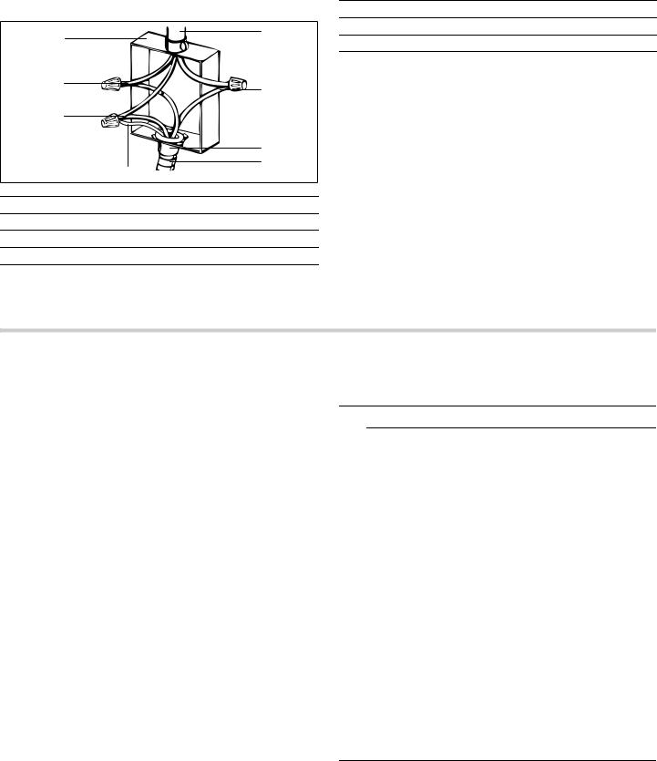
Four-wire Connection
|
|
|
|
|
|
|
|
|
|
||||||
|
|
|
|
|
|
||
|
|
|
|
|
|
|
|
|
|
|
|
|
|
||
|
|
|
|
|
|
|
|
|
|
|
|
|
|
|
|
|
|
|
|
|
|
|
|
|
|
|
|
|
|
|
|
|
|
|
|
|
|
|
1 Cable from power supply
2 White wires
3Black wires
4 U.L.-listed conduit connector
5Cable from oven
6 Bare or green wires
7Red wires
8Junction box
Connect the red oven wire to the red electrical supply wire (hot wire).
Connect the black oven wire to the black electrical supply wire (hot wire).
Connect the white neutral oven wire to the white neutral (not bare ground) electrical supply wire.
Connect the oven bare ground wire to the bare (or green) electrical supply ground wire.
8
Three-wire Connection
1 Cable from power supply
2Black wires
3 U.L.-listed conduit connector
4 Cable from oven
5Bare or green wire
6 White wires
7Red wires
8Junction box
Connect red wire from oven to red electrical supply wire.
Connect black wire from oven to black electrical supply wire.
Connect both the bare ground wire and the white wire from the oven to the white (or gray) neutral electrical supply wire, or the bare/green ground electrical supply wire.
The conduit cable, where connected at the oven, swivels. Rotate conduit cable upward (or downward) and direct through hole prepared in cabinet to attach to junction box.
To maintain serviceability, the flex conduit must not be shortened and should be routed to permit temporary removal of the oven.
Oven Installation
NOTICE: Before installing the oven, be sure to verify the cabinet dimensions and electrical connections.
For Best Installation
The oven can be difficult for two people to handle during installation. It is recommended to have three or more people available to assist with lifting the unit into place.
Removal of the oven door during installation (to provide the necessary handholds and to significantly reduce the unit weight) can be cumbersome unless the detailed door removal instructions are followed carefully. Please take time to read and follow the instructions provided for an improved installation experience.
Removing the Oven Door
9CAUTION
WHEN REMOVING THE OVEN DOOR:
Make sure oven is cool and power to the oven has been turned off before removing the door. Failure to do so could result in electrical shock or burns.
The oven door is heavy and parts of it are fragile. Use both hands to remove the oven door. The door front includes glass components. Handle carefully to avoid breakage.
Grasp only the sides of the oven door. Do not grasp the handle as it may swing in your hand and cause damage or injury.
Failure to grasp the oven door firmly and properly could result in personal injury or product damage.
To avoid injury from hinge bracket snapping closed, be sure that both locking levers are securely in place before removing the door. Also, do not force the oven door open or closed - the hinge could be damaged and injury could result.
Do not lay the removed door on sharp or pointed objects as this could break the glass. Lay the door on a flat, smooth surface, positioned so that the door cannot fall over.
9

To remove the oven door:
1.Read the preceeding caution notice before beginning the oven door removal process.
2.Provide a nearby place to safely lay the door after removal so it will not fall over or be stepped upon. Lay the door flat on a blanket or cushioned surface.
3.Open the oven door fully until it is parallel to the floor. The door contains powerful springs to assist with closing the door. It is necessary to position the toggle locks in place to take the tension off the springs.
4.To access the toggle locks, remove the locking plate using a T20 star head driver.
5.After removing the screw, (A) lift the locking plate up and then pivot it out to remove. Repeat for the other hinge. Retain both locking plates and screws for reinstallation.
6.Flip the locking levers towards the door as far as they will go. Hint: (B) It may be helptul to use the tip of a screwdriver to pull out the locking levers. (C) Make sure both locking levers are in the locked position pushed all the way towards the door.
7.With the toggles in place as shown, carefully close the oven door until the front side of the door is about
5½ inches (140 mm) from the control panel.
8.Grasp the door firmly using both hands. The door weighs over 30 pounds.
9CAUTION
To avoid damage do not allow the door to strike the control panel during door removal or replacement.
10
9.Lift the door up and pull out at an upward angle as shown in the following illustration. The notch in the hinge foot will disengage from the oven door frame. With both door hinge feet disengaged, lift the door off the unit.
10.Carefully move the door to a safe place to protect it from damage until you are ready to reinstall it.
Placing the Oven into the Cabinet Opening
9CAUTION
To avoid potential damage to flooring keep the unit on its base packaging until immediately before placing the unit directly into the cabinet opening. Do not allow the metal base of the unit to contact the flooring. See the following handling instructions for details.
To avoid damage to the door (and/or warming drawer front for combo units) do not lift, pull or push the unit during installation by using the oven door handle or warming drawer handle as a gripping point.
Wear gloves and long sleeves to protect hands and forearms from abrasion and potential scratches during the lifting process. Take off watches and jewelry and wear work shoes during installation for foot protection.
When lifting the unit into place avoid grasping the upper element to avoid damaging it. See the following illustration for the correct lifting point.
1.The unit and its bottom packaging (pallet) should be positioned close to and in front of the cabinet opening prior to beginning to lift the unit into place.
2.Lift or slide unit into the cabinet cutout without allowing the unit base to contact the flooring.
11
3.Guide the unit straight back into the cabinet cutout. Push the unit straight in until the oven trim is about
2 inches from being flush with cabinet wall. Be careful not to crimp the flexible conduit between the oven and the cabinet back wall. If necessary, guide the flexible conduit into the wall or cabinet access hole so it doesn’t prevent the unit from being pushed all the way into the cabinet opening. The oven should be straight and level, not crooked.
4.Push the unit all the way back into the cabinet cutout until the front edge of the unit is flush with the front of the cabinet.
5.Install the supplied screws through the tap holes in the trim (2 screws for single ovens, 4 screws for double/ combo ovens). It is recommended to drill pilot holes for the trim screws.
6.Replace the oven door(s) according to the following instructions.
Replacing the Oven Door
To replace the oven door:
1.Hold the door firmly in both hands at a 30° angle to the front of the unit.
2.Guide the door hinges into the hinge slots on the unit housing.
3.Slide the door in until the slots on the hinges engage the oven housing. Hint: it may be necessary to rock the door slightly to seat it correctly.
4.Lower the door into the fully open 90° position. If the door will not lower all the way to the 90° position, the hinges are not correctly seated. The door should be straight, not crooked.
5.Push the locking toggles back into the unlocked position, toward the oven cavity.
6.Reinstall the locking plates and screws (see door removal process above).
7.Close the door gently. It should close all the way. Gently open and close the door several times to be sure it is correctly installed and securely in place.
Combination Units Microwave Trim
Adjustment
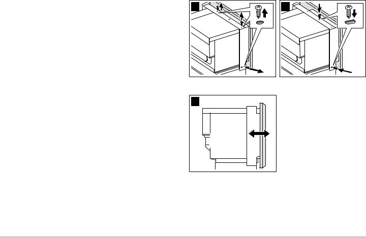
During the installation of your Built-In Oven combination unit it may be necessary to adjust the microwave trim frame for a tight fit against the cabinet front. Determine if alignment of the microwave trim frame is needed to fit the trim tighter against the cabinet front.
1.Measure the gap dimension to be closed and note on which side it appears.
2.Slide the Built-In Oven unit out from the cabinet 4 to 5 inches, enough to provide access to the adjustment screws.
3.Remove screws (A) and replace into adjustable slot positions (B). Do not tighten the screws.
4. Slide the trim frame as needed (C).
5.Tighten the screws holding the trim frame.
6.Slide the oven unit fully back into place in the cavity and check to see if the alignment of the microwave trim frame is satisfactory. If it is not, repeat the procedure.
Testing Operation
1.Turn on power at the breaker.
2.Check power at junction box using a volt meter.
For 240 V installation, the reading between the red and black wires (line to line) should be 220 to 240 volts.
For 208 V installation, the reading between the red and black wires (line to line) should be 190 to 208 volts.
3.Test the oven mode.
Select the BAKE mode. See the Use and Care Manual for detailed operation instructions.
4.Verify that the oven light comes on and the oven begins to preheat.
5.Test the door lock.
Set the SELF CLEAN mode. Confirm that the door locks when the lock icon appears in the display.
6.If installing a double oven, test the second oven as well.
7.If any of the tests do not result as explained above, contact service for assistance. Otherwise, the installation is complete at this time.
12

Service
Before Calling Service
See Use and Care Manual for troubleshooting information. Refer to the Warranty in the Use and Care Manual.
To reach a service representative, see the contact information at the front of the manual. Please be prepared with the information printed on your product data plate when calling.
Data Plate
The data plate shows the model and serial number. Refer to the data plate on the appliance when requesting service.
The data plate is located on the underside of the control panel:
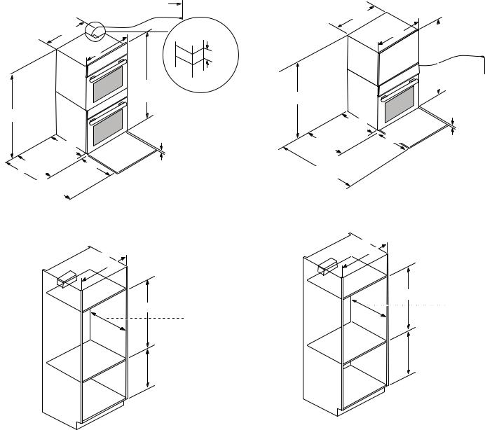
Appliance and Cabinet Cutout Dimensions
Dimensions for 27” Wall-Mounted Units |
Wall Installation 27” Ovens: |
||
Single Oven 27” |
|
|
|
|
|
|
|
|
|
|
|
|
|
|
|
|
|
|
|
|
|
|
|
|
|
|
|
|
|
|
|
|
|
|
|
|
|
|
|
|
|
|
|
|
|
||
|
|
|
|
|
|
|
! |
|
|
|
|
|
|
|
"#! |
|
|
|
$ |
|
|
|
|
|
|
|
|
|
|
|
|
|
|
|
|
|
|
||
|
|
||
|
|
|
|
|
|
|
|
|
|
|
|
It is good practice, when oven is installed at the end of a cabinet run, adjacent to a perpendicular wall or cabinet door, to allow at least 1/4” space between the side of the oven and the wall/door.
For oven support, install 2x4’s extending front to back flush with the bottom and the side of the opening. The supporting base must be well secured to the floor/ cabinet and level.
NOTICES
The conduit box must be installed either above or below the unit. If the conduit box is installed below the unit, a 2” diameter hole or space is required between the back wall and the right rear of the 2x4 supports.
The cabinet base must be flat and capable of supporting a weight of at least 193 lbs (87 kg).
13

Double Oven 27”
|
|
|
|
|
|
|
|
|
|
|
|
|
|
||
|
|
|
|
|
|
|
|
|
|
|
|
|
|
|
|
|
|
|
|
|
|
|
|
|
|
|
|
|
|
||
|
|
||
|
|
||
|
|||
|
|||
|
|
||
|
|
||
|
|
|
|
|
|
|
|
Wall Installation 27” Double Oven:
%
! "#!
$
27” Combo Oven with Microwave and Warming Drawer
|
|
|
|
|
|
|
|
|
|
|
|
|
|
|
|
|
|
|
|
|
|
|
|
|
|
|
|
|
|
|
|
|
|
|
|
Wall Installation 27” Combo Oven with Microwave and Warming Drawer:
 ! "#! &
$
It is good practice, when oven is installed at the end of a cabinet run, adjacent to a perpendicular wall or cabinet door, to allow at least 1/4” space between the side of the oven and the wall/door.
For oven support, install 2x4’s extending front to back flush with the bottom and the side of the opening. The supporting base must be well secured to the floor/ cabinet and level.
NOTICES
The conduit box must be located above the unit to facilitate connecting and servicing.
The cabinet base must be flat and capable of supporting a weight of at least 361 lbs (164 kg).
It is good practice, when oven is installed at the end of a cabinet run, adjacent to a perpendicular wall or cabinet door, to allow at least 1/4” space between the side of the oven and the wall/door.
For oven support, install 2x4’s extending front to back flush with the bottom and the side of the opening. The supporting base must be well secured to the floor/ cabinet and level.
NOTICES
The conduit box must be located above the unit to facilitate connecting and servicing.
The cabinet base must be flat and capable of supporting a weight of at least 369 lbs (167 kg).
14

Dimensions for 27” Under-Counter Units
|
' |
|
|
|
|
|
|
|
|
|
|
|
|
|
|
|
|
|
|
|
|
|
|
|
' |
|
|
|
|
* Includes ¾” (19 mm) base plate. For single ovens installed under a cabinet, the junction box should be located to the right of the unit within reach of the power cord.
It is good practice, when oven is installed at the end of a cabinet run, adjacent to a perpendicular wall or cabinet door, to allow at least 1/4” space between the side of the oven and the wall/door.
For oven support, install 2x4’s extending front to back flush with the bottom and the side of the opening. The supporting base must be well secured to the floor/ cabinet and level.
Note: The cabinet base must be flat and capable of supporting a weight of at least 193 lbs (87 kg).
Dimensions for 30” Wall-Mounted Units
30” Single Oven
|
|
|
|
|
|
|
|
|
|
|
|
|
|
|
|
|
|
|
|
|
|
( |
|
|
|
|
|
|
|
|
|
|
|
|
|
|
|
|
|
|
|
|
|
|
|
|
|
|
|
|
|
|
|
|
|
|
|
||
|
|
||
|
|
|
|
|
|
|
|
|
|
|
|
|
|
|
|
Wall Installation 30” Single Oven:
! "#!
$
It is good practice, when oven is installed at the end of a cabinet run, adjacent to a perpendicular wall or cabinet door, to allow at least 1/4” space between the side of the oven and the wall/door.
For oven support, install 2x4’s extending front to back flush with the bottom and the side of the opening. The supporting base must be well secured to the floor/ cabinet and level.
NOTICES
The conduit box must be installed either above or below the unit. If the conduit box is installed below the unit, a 2” diameter hole or space is required between the back wall and the right rear of the 2x4 supports.
The cabinet base must be flat and capable of supporting a weight of at least 212 lbs (96 kg).
15
30” Double Oven
|
|
|
|
|
|
|
|
|
|
|
|
|
|
|
|
( |
|
|
|
|
|
|
|
|
|
|
|
|
|
|
|
|
|
|
|
|
|
|
|
|
|
||
|
|
||
|
|
||
|
|||
|
|||
|
|
||
|
|
||
|
|
|
|
|
|
|
|
Wall Installation 30” Double Oven:
%
! "#!
$
30” Combo Oven with Microwave
|
|
|
|
|
|
|
|

|
|
|
|
|
|
|
|
|
|
|
|
|
|
|
|
|
|
Wall Installation 30” Combo Oven with Microwave:
! "#!
$
It is good practice, when oven is installed at the end of a cabinet run, adjacent to a perpendicular wall or cabinet door, to allow at least 1/4” space between the side of the oven and the wall/door.
For oven support, install 2x4’s extending front to back flush with the bottom and the side of the opening. The supporting base must be well secured to the floor/ cabinet and level.
NOTICES
The conduit box must be installed either above or below the unit. If the conduit box is installed below the unit, a 2 inch diameter hole or space is required between the back wall and the right rear of the 2x4 supports.
The cabinet base must be flat and capable of supporting a weight of at least 390 lbs (177 kg).
It is good practice, when oven is installed at the end of a cabinet run, adjacent to a perpendicular wall or cabinet door, to allow at least 1/4” space between the side of the oven and the wall/door.
For oven support, install 2x4’s extending front to back flush with the bottom and the side of the opening. The supporting base must be well secured to the floor/ cabinet and level.
NOTICES
The conduit box must be installed either above or below the unit. If the conduit box is installed below the unit, a 2 inch diameter hole or space is required between the back wall and the right rear of the 2x4 supports.
The cabinet base must be flat and capable of supporting a weight of at least 310 lbs (141 kg).
16
Loading...