


INSTALLATION MANUAL
For THERMADOR PROFESSIONAL®
PRO GRAND® Dual Fuel Ranges
MANUAL D’INSTALLATION
Pour cuisinières mixtes PROFESSIONAL PRO GRANDmc de THERMADOR
MANUAL DE INSTALACIÓN
Para estufas mixtas PROFESSIONAL PRO GRAND® de THERMADOR
Models/
Modèles/
Modelos:
PRD364JDGC
PRD364JDGU
PRD366JGC
PRD366JGU
PRD486JDGC
PRD486JDGU
PRD48JDSGC
PRD48JDSGU


Table of Contents
Safety Instructions . . . . . . . . . . . . . . . . . . . . . . . . . . . . . . . . 1
Before You Begin . . . . . . . . . . . . . . . . . . . . . . . . . . . . . . . . . . . . . . . . . . . . . . . . . 1
Installation . . . . . . . . . . . . . . . . . . . . . . . . . . . . . . . . . . . . . . . 3 |
|
Planning Information . . . . . . . . . . . . . . . . . . . . . . . . . . . . . . . . . . . . . . . . . . . . . |
. 3 |
Step 1: Ventilation Requirements . . . . . . . . . . . . . . . . . . . . . . . . . . . . . . . . . . . . |
3 |
Step 2: Cabinet Preparation . . . . . . . . . . . . . . . . . . . . . . . . . . . . . . . . . . . . . . . . |
4 |
Step 3: Unpacking & Moving the Range . . . . . . . . . . . . . . . . . . . . . . . . . . . . . . . |
9 |
Step 4: Door Removal & Adjustment . . . . . . . . . . . . . . . . . . . . . . . . . . . . . . . . |
11 |
Step 5: Installing Anti-Tip Device . . . . . . . . . . . . . . . . . . . . . . . . . . . . . . . . . . . |
12 |
Step 6: Gas Requirements and Hookup . . . . . . . . . . . . . . . . . . . . . . . . . . . . . . |
14 |
Step 7: Electrical Requirements, Connection & Grounding . . . . . . . . . . . . . . . |
16 |
Step 8: Backguard Installation (optional) . . . . . . . . . . . . . . . . . . . . . . . . . . . . . |
19 |
Step 9: Placing and Leveling the Range . . . . . . . . . . . . . . . . . . . . . . . . . . . . . . |
24 |
Step 10: Burner Test and Adjustment . . . . . . . . . . . . . . . . . . . . . . . . . . . . . . . . |
28 |
Installer Final Check List . . . . . . . . . . . . . . . . . . . . . . . . . . 29 Customer Support, Accessories & Parts . . . . . . . back page
This THERMADOR® appliance is made by BSH Home Appliances Corporation 1901 Main Street, Suite 600
Irvine, CA 92614
Questions?
1-800-735-4328
www.thermador.com
We look forward to hearing from you!

Safety
IMPORTANT SAFETY INSTRUCTIONS
READ AND SAVE THESE INSTRUCTIONS
APPROVED FOR ALL RESIDENTIAL APPLIANCES FOR RESIDENTIAL USE ONLY
Before You Begin
IMPORTANT: Save these Instructions for the Local Gas Inspector’s use.
INSTALLER: Please leave these Installation Instructions with this unit for the owner.
OWNER: Please retain these instructions for future reference.
 WARNING:
ELECTRICAL SHOCK HAZARD—
Disconnect power before installing or servicing. Before turning power ON, be sure that all controls are in the OFF position. Failure to do so can result in death or electrical shock.
IMPORTANT:
Local codes vary. Installer is responsible for ensuring that the installation, gas connections, and grounding comply with all applicable codes. Failure to follow appropriate local
codes and regulations may void the warranty.
For Massachusetts Installations:
1.Installation must be performed by a qualified or licensed contractor, plumber or gas fitter qualified or licensed by the state, province or region where this appliance is being installed.
2.Shut-off valve must be a “T” handle gas cock.
3.Flexible gas connector must not be longer than 36” (914 mm).
Note:
This range is NOT designed for installation in manufactured (mobile) homes or recreational park trailers.
DO NOT install this range outdoors.
 WARNING:
A child or adult can tip the range over and be killed or seriously injured. Verify that the anti-tip bracket is securely installed.
Ensure the anti-tip bracket is engaged when the range is moved.
Do not operate the range without the antitip bracket in place. Failure to follow the instructions in this manual can result in death or serious burns to children and adults.
Check for proper installation and use of anti-tip bracket. Carefully tip range forward pulling from the back to ensure that the anti-tip bracket engages the range aluminum cast base and prevents tip-over. Range should not move more than 1 inch (2.5 cm).
 WARNING:
If the information in this manual is not followed exactly, a fire or explosion may result causing property damage, personal injury or death.
—Do not store or use gasoline or other flammable vapors and liquids in the vicinity of this or any other appliance.
—WHAT TO DO IF YOU SMELL GAS
•Do not try to light any appliance.
•Do not touch any electrical switch.
•Do not use any phone in your building.
•Immediately call your gas supplier from a neighbor’s phone. Follow the gas supplier’s instructions.
•If you cannot reach your gas supplier, call the fire department.
—Installation and service must be performed by a qualified installer, service agency or the gas supplier.
English 1
IMPORTANT SAFETY INSTRUCTIONS
READ AND SAVE THESE INSTRUCTIONS
Gas Type Verification
Verify that the appliance is correct for the type of gas provided at installation location. Ensure that the appliance is connected to the type of gas for which it is certified. Before proceeding with the installation refer to “Step 6: Gas Requirements and Hookup” on page 14 for specifications.
All models are certified for use with natural gas. Field conversion of the appliance for use with propane gas supply will require installation of conversion kit, supplied with the range (service number 553182). Only a qualified service technician or installer should make this conversion. See LP Conversion Kit Instruction for full installation information.
Gas Supply:
Natural Gas – 6” water column (14.9 mb) min., 14” (34.9 mb) maximum
Propane Gas – 11” water column (27.4 mb) min., 14” (34.9 mb) maximum
State of California Proposition 65 Warnings:
WARNING: This product contains one or more chemicals known to the State of California to cause cancer.
WARNING: This product contains one or more chemicals known to the State of California to cause birth defects or other reproductive harm.
Electric Power Supply:
See “Step 7: Electrical Requirements, Connection & Grounding” on page 16 for specifications.
Check local building codes for the proper method of appliance installation. Installation, electrical connections and grounding must comply with all applicable codes. Local codes vary and it is the responsibility of the installer to ensure installation is in accordance with these codes. In the absence of local codes the appliance should be installed in accordance with the National Fuel Gas Code ANSI Z223.1/ NFPA 54 current issue and National Electrical Code ANSI/ NFPA 70-current issue. In Canada, installation must be in accordance with the CAN 1-B149.1 and .2 – Installation Codes for Gas Burning Appliances and/or local codes.
Safety Codes and Standards
This appliance complies with the following standards:
•UL 858, Standard for the Safety of Household Electric Ranges
•ANSI Z21.1, American National Standard for Household Cooking Gas Appliances
•CAN 1-1. 1-M81, Domestic Gas Ranges
•CAN/CSA-C22.2 No. 61, Household Cooking Ranges
It is the responsibility of the owner and the installer to determine if additional requirements and/or standards apply to specific installations.
IMPORTANT:
When installing against a combustible surface, a High Shelf or Low Backguard is required. A THERMADOR® High Shelf or Low Backguard must be purchased separately. See Step 8 on page 19 for backguard and installation information.
When using the Flush Island Trim, THERMADOR recommends a minimum 12” (305 mm) rear clearance to a combustible surface (see Figure 1, Cabinet Clearances). Clearances from non-combustible materials are not part of the ANSI Z21.1 scope and are not certified by
CSA. Clearances of less than 12” (305 mm) must be approved by the local codes and/or by the local authority having jurisdiction.
Refer to Table 4, “Backguard Kit Model Numbers,” on page 19, for the correct backguard models that are designed for this range. After selecting the correct backguard, the range must be installed properly, using the minimum clearances to combustible surfaces specified in
“Step 2: Cabinet Preparation” on page 4.
 WARNING:
To avoid possible burn or fire hazard, a backguard designed specifically for this range must be installed whenever the range is used.
 CAUTION:
To eliminate risk of burns or fire caused by reaching over heated surface units, cabinet storage located above the surface units should be avoided.
English 2

Installation
Planning Information
Before using your appliance, be sure to read this manual. Pay special attention to the Important Safety Instructions
located at the beginning of the manual.
Tools Needed
(2) 1/2” wrenches |
1/8” (3.17 mm) drill bit |
|
|
3/16” (4.76 mm) drill bit |
12” adjustable wrench |
|
|
Hand or electric drill |
Tape measure |
|
|
Phillips & flathead screwdrivers |
Marking instrument |
|
|
Level |
Furniture dolly |
|
|
T-20 Torx screwdriver |
Protective gloves |
|
|
Items Not Included |
|
|
|
Drywall/Concrete Anchors |
Pipe Compound/Tape |
|
|
Rope/Twine |
¾” (19 mm) Flex Line |
|
|
Strain Relief |
|
|
|
Remove all tape and packaging before using the appliance. Please, recycle the packaging material, as all THERMADOR® appliance packaging material is recyclable. Never allow children to play with packaging material.
Step 1: Ventilation
Requirements
It is strongly recommended that this appliance be installed in conjunction with a suitable overhead vent hood. Due to the high heat capability of this unit, particular attention should be paid to the hood and duct work installation to assure it meets local building codes.
Downdraft ventilation should not be used. Table 1, Blower Options indicates the ventilation hood options and blower capacity guidelines that are recommended for use with all THERMADOR® ranges.
Due to the high heat of the rangetop burners, do not install a microwave oven/ventilator combination above the range, as these type of units do not provide the proper ventilation and are not suitable for use with the range.
IMPORTANT:
Ventilation hoods and blowers are designed for use with single wall ducting. However, some local building codes or inspectors may require double wall ducting. Consult local building codes and/or local agencies before starting to assure that hood and duct installation will meet local requirements.
NOTICE:
Most range hoods contain combustible components which must be considered when planning the installation.
 WARNING:
This appliance should not be installed with a ventilation system that directs air in a downward direction toward the range. This type of ventilation system may cause ignition and combustion problems with the appliance resulting in personal injury, property damage, or unintended operation. Ventilating systems that direct the air upwards do not have any restriction.
Ventilation Preparation
1. Select Hood and Blower Models:
•For wall installations, the hood width must, at a minimum, equal the width of the range. Where space permits, a hood larger in width than the range may be desirable for improved ventilation performance.
•For island installations, the hood width should overhang the range by a minimum of 3" (76 mm) on each side.
2. Hood Placement:
•For best smoke elimination, the lower edge of the hood should be installed 30" (762 mm) above the range cooking surface.
•If the hood contains any combustible materials (i.e. a wood covering), it must be installed a minimum of 36" (914 mm) above the cooking surface (Figure 1 on page 5).
3. Consider Make-Up Air:
•Due to the high volume of ventilation air, a source of outside replacement air is recommended. This is particularly important for tightly sealed and insulated homes. A qualified heating and ventilating contractor should be consulted.
English 3

Range |
Range Top |
Cubic Feet per Minute |
Ventilation Options |
|
Width |
Configuration |
(min. requirement) |
||
|
||||
|
|
|
|
|
|
4 burners with griddle |
800 (cfm) |
36” or 42” Pro Wall Hood |
|
36” |
|
|
36” Custom Insert w/ optional blower |
|
6 burners |
1100 (cfm) |
|||
|
42” or 48” Island Hood w/ optional blower |
|||
|
|
|
||
|
|
|
|
|
48” |
6 burners with griddle |
1200 (cfm) |
48” or 54” Pro Wall Hood |
|
|
|
|
48” Custom Insert w/ optional blower |
|
|
|
|
|
|
IMPORTANT NOTES: |
|
|
||
•It is recommended that a THERMADOR PROFESSIONAL® wall or island hood or custom insert is used with THERMADOR PROFESSIONAL ranges. Refer to www.thermador.com for a complete selection of ventilation options, blowers, and accessories.
•For high output gas ranges (60,000 BTU or greater), the minimum of one (1) CFM of ventilation per 100 BTU is recommended. If the range has a griddle, add 200 CFM to the estimated blower capacity. Additional blower capacity may be required for longer duct runs. (CFM = “cubic feet per minute”, standard blower capacity rating).
•For island applications, it is recommended to use a hood width that exceeds the width of the range by 6” (152 mm), overlapping the range by a minimum of 3” (76 mm) on each end.
Step 2: Cabinet Preparation
•The range is a free standing unit. If the unit is to be placed adjacent to cabinets, the clearances shown in
“Installation Clearances” on page 5 are required. The same clearances apply to island installations, except for the overhead cabinets, which must have a space wide enough to accept the flared island hood.
•The range should not be recessed into the cabinets beyond the edge of the front face of the oven (see clearances beginning on page 6).
•The gas and electrical supply should be within the zones shown in Figure 4 on page 8.
•Any openings in the wall behind the range and in the floor under the range must be sealed.
•When installing against a combustible surface, a High Shelf or Low Backguard is required. A THERMADOR® High Shelf or Low Backguard must be purchased separately (see Table 4, “Backguard Kit Model Numbers,” on page 19).
•When using the Flush Island Trim, THERMADOR recommends a minimum 12” (305 mm) rear clearance to a combustible surface (see Figure 3, Installation Clearances with Flush Island Trim). Clearances from non-combustible materials are not part of the ANSI Z21.1 scope and are not certified by CSA. Clearances of less than 12” (305 mm) must be approved by the local codes and/or by the local authority having jurisdiction.
•When the range is installed against a combustible side wall a minimum clearance of 5” (127 mm) is needed from the side of the range to the wall (Figure 1).
Table 1: Blower Options
•Always keep appliance area clear from combustible materials, gasoline and other flammable vapors and liquids.
•The maximum depth of overhead cabinets installed on either side of the hood is 13" (330 mm) (Figure 1).
•Do not obstruct the flow of combustion and ventilation air to the unit.
•There is a 36” (914 mm) minimum clearance required between the top of the cooking surface and the bottom of an unprotected cabinet. A 30” (762 mm) clearance can be used when the bottom of the wood or metal cabinet is protected by not less than 1/4” (6 mm) of a flame retardant material covered with not less than No. 28 MSG sheet steel, 0.015” (0.38 mm) thick stainless steel, 0.024” (0.61 mm) aluminum, or 0.02” (0.51 mm) thick copper (Figure 1).
Flame retardant materials bear the mark: UNDERWRITERS LABORATORIES INC. CLASSIFIED MINERAL AND FIBER BOARDS SURFACE BURNING CHARACTERISTICS, followed by the flame spread and smoke ratings. These designations are shown as “FHC (FIame Spread/Smoke Developed).” Materials with “O” flame spread ratings are flame retardant. Local codes may allow other flame spread ratings. It is the responsibility of the installer to ensure installation is in accordance with these ratings.
English 4
Installation Clearances
|
|
\ |
|
|
'PS w 3BOHFT |
w PS w PS NN 8JEF )PPE |
|||
w PS w PS NN GPS *TMBOE |
||||
|
|
|||
|
|
\ |
|
|
'PS w 3BOHFT |
w PS i PS NN 8JEF )PPE |
|||
w NN GPS *TMBOE |
||||
|
|
|
|
|
|
|
|
|
|
|
|
|
|
|
|
|
|
|
|
PP PLQ IURPERWWRPRI RYHUKHDG KRRGWR&RRNLQJ 6XUIDFHPP PLQ LI KRRG FRQWDLQV FRPEXVWLEOH PDWHULDOV
´ PP PLQLPXP
Ǭ´ PP 0LQ UDQJH KHLJKW ZLWK OHYHOLQJ OHJV IXOO\ UHWUDFWHG
ô´ PP 0D[ UDQJH KHLJKW ZLWK OHYHOLQJ OHJV IXOO\ H[WHQGHG
7KH UDQJH KHLJKW LV DGMXVWDEOH 7KH OHYHO RI WKH UDQJH WRS PXVW EH DW WKH VDPH OHYHO RU DERYH WKH FRXQWHU WRS OHYHO
0LQ 'LVWDQFH %HWZHHQ 2YHUKHDG &DELQHWV RI &RPEXVWLEOH 0DWHULDO
5DQJH ± PP
5DQJH ± PP
´ PP
PD[ &DELQHW GHSWK
´ PP PLQ WR FRPEXVWLEOH
VLGHZDOO PDWHULDO 5DQJH :LGWK ERWK VLGHV
´ RU ´ RU PP
)RU *DV 6XSSO\ (OHFWULFDO =RQHV VHH )LJXUH
=RQH VL]HV SRVLWLRQV GLIIHU DFFRUGLQJ WR PRGHO
|
|
|
/ |
*$6 =21( |
|
(/(&75,&$ |
|
|
=21( |
|
|
H$"65*0/
4FF 'JH 'JHw NN NJO UP DPNCVTUJCMF NBUFSJBM GSPN $PPLJOH 4VSGBDF
&RRNLQJ
6XUIDFH
$V GHILQHG LQ WKH ³1DWLRQDO )XHO *DV &RGH´ $16, = &XUUHQW (GLWLRQ &OHDUDQFHV IURP QRQ FRPEXVWLEOH PDWHULDOV DUH QRW SDUW RI WKH $16, = VFRSH DQG DUH QRW FHUWLILHG E\ &6$ &OHDUDQFHV RI OHVV WKDQ ´ PP PXVW EH DSSURYHG E\ WKH ORFDO FRGHV DQG RU E\ WKH ORFDO DXWKRULW\ KDYLQJ MXULVGLFWLRQ
 CAUTION:
Do not install the range such that the oven door is flush with the cabinet face. A flush installation could result in damage to the cabinets due to exposure to high heat.
Figure 1: CABINET CLEARANCES
English 5
,QVWDOODWLRQ &OHDUDQFHV ZLWK +LJK 6KHOI RU /RZ %DFNJXDUG |
||
|
|
&RPEXVWLEOH |
|
|
0DWHULDOV |
|
ó´ PP |
|
|
ǩ´ PP |
|
PP PLQ |
ô´ PP |
|
WR FRPEXVWLEOH |
|
|
PDWHULDOV |
|
|
|
+LJK 6KHOI |
|
|
´ PP |
ǩ´ |
|
|
|
|
|
PP |
|
/RZ %DFN |
´ PP |
|
|
&RPEXVWLEOH |
|
ǩ´ PP |
%DFN :DOO |
|
|
|
ô´ PP 0D[ |
PD[ UHFHVV GHSWK |
|
|
|
|
Ǭ´ PP 0LQ |
|
|
|
Ǭ´ PP |
|
|
ô´ PP |
|
$V GHILQHG LQ WKH ³1DWLRQDO )XHO *DV &RGH´ $16, = &XUUHQW (GLWLRQ |
|
|
&OHDUDQFHV IURP QRQ FRPEXVWLEOH PDWHULDOV DUH QRW SDUW RI WKH $16, = |
|
|
VFRSH DQG DUH QRW FHUWLILHG E\ &6$ &OHDUDQFHV RI OHVV WKDQ ´ PP |
|
|
PXVW EH DSSURYHG E\ WKH ORFDO FRGHV DQG RU E\ WKH ORFDO DXWKRULW\ KDYLQJ MXULVGLFWLRQ |
|
|
Figure 2: Installation Clearances with High Shelf or Low Backguard
English 6

,QVWDOODWLRQ &OHDUDQFHV ZLWK )OXVK ,VODQG 7ULP
PP PLQ WR FRPEXVWLEOH PDWHULDOV
´ PP PLQ WR FRPEXVWLEOH VXUIDFH ZLWK )OXVK ,VODQG 7ULP
 ó´ PP
ó´ PP 
 ǩ´ PP
ǩ´ PP
ô´ PP 0D[Ǭ´ PP 0LQ


 ǩ´ PP
ǩ´ PP
PD[ UHFHVV GHSWK
Ǭ´ PP |
 ô´ PP
ô´ PP 
&RPEXVWLEOH 0DWHULDOV
127( )RU )OXVK ,VODQG 7ULP LQVWDOODWLRQV FRXQWHU VXUIDFH VKRXOG KDYH D FDQWLOHYHU HGJH PHHWLQJ WKH EDFN VHFWLRQ RI WKH )OXVK ,VODQG 7ULP DFFHVVRU\
&DQWLOHYHU
127( ,I DQ LQQHU ZDOO LV XVHG XQGHU WKH FDQWLOHYHU FRXQWHU WRS WKHUH VKRXOG EH D ǩ´ PP JDS IURP WKH UHDU RI WKH UDQJH WR WKH LQQHU ZDOO
DV GHILQHG LQ WKH ³1DWLRQDO )XHO *DV &RGH´ $16, = &XUUHQW (GLWLRQ &OHDUDQFHV IURP QRQ FRPEXVWLEOH PDWHULDOV DUH QRW SDUW RI WKH $16, = VFRSH DQG DUH QRW FHUWLILHG E\ &6$ &OHDUDQFHV RI OHVV WKDQ ´ PP PXVW EH DSSURYHG E\ WKH ORFDO FRGHV DQG RU E\ WKH ORFDO DXWKRULW\ KDYLQJ MXULVGLFWLRQ
Figure 3: Installation Clearances with Flush Island Trim
English 7
Gas and Electric Supply Zones
5DQJH :LGWK´ RU ´ RU PP
|
|
(/(&75,&$/ |
|
|
*$6 =21( |
=21( |
|
´ |
|
´ |
|
PP |
|
|
|
PP |
|
||
|
|
||
$ |
% |
& |
' |
|
|||
|
|
||
 ´ PP PD[ SURWUXVLRQ IURP ZDOO IRU JDV RU HOHFWULFDO VXSSO\
0RGHO |
$ |
% |
& |
' |
´ PP |
ǩ´ PP |
Ǫ´ PP |
Ǫ´ PP |
ǩ´ PP |
´ PP |
ǩ´ PP |
´ PP |
´ PP |
Ǭ´ PP |
NOTICE:
—If not already present, install gas shut-off valve in an easily accessible location.
—Make sure all users know where and how to shut off the gas supply to the range.
—Any opening in the wall behind the appliance and any opening in the floor under the appliance must be sealed.
The dual fuel ranges may be connected to the power supply with a range supply cord kit or by hard-wiring to the power supply. It is the responsibility of the installer to provide the proper wiring components (cord or conduit and wires) and complete the electrical connection as dictated by local codes and ordinances, and/or the National Electric Code. The units must be properly grounded. Refer to
“Step 7: Electrical Requirements, Connection & Grounding” on page 16 for details.
Figure 4: Gas & Electrical Supply Locations
The range must be connected only to the type of gas for which it is certified. If the range is to be connected to propane gas, ensure that the propane gas supply tank is equipped with its own high pressure regulator in addition to the pressure regulator supplied with the range (see
“Step 6: Gas Requirements and Hookup” on page 14).
NOTE:
The range is designed for nearly-flush installation to the back wall. For a successful installation, it may be necessary to reposition the gas supply line and electrical cord as the range is pushed back to its final position.
--SUGGESTION: This may be accomplished by carefully pulling on a rope or twine looped around the gas or electrical supply line as the range is pushed back into its final installed position.
English 8

Electrical Supply
Installation of the range must be planned so that the roughin of the terminal block for the receptacle or conduit connection will allow maximum clearance to the rear of the unit.
When the power supply cord or conduit is connected to the mating receptacle or terminal block cover, the combined connection should protrude no more than 2” (51 mm) from the rear wall (see Figure 5).
To minimize binding when the unit is connected, orient the receptacle or conduit connector, and slide back into position.
1PXFS $PSE 3FDFQUBDMF |
+VODUJPO #PY $POEVJU |
w NN NBY |
w NN |
XIFO QMVHHFE JO |
NBYJNVN |
Step 3: Unpacking and Moving
the Range
 CAUTION:
The unit is heavy and should be handled accordingly. Proper safety equipment such as gloves and adequate manpower of at least two people must be used in moving the range to avoid injury and to avoid damage to the unit or the floor. Rings, watches, and any other loose items that may damage the unit or otherwise might become entangled with the unit should be removed.
Hidden surfaces may have sharp edges. Use caution when reaching behind or under appliance.
Figure 5: Wall Connection
NOTE:
Canadian models have power cord supplied with range.
 CAUTION:
Do not use a hand truck or appliance dolly on the back or front of the unit. Handle from the side only.
Unpacking the Range
 CAUTION:
DO NOT lift the range by the oven door’s handle, as this may damage the door hinges and cause the door to fit incorrectly.
1.Remove the outer carton and packing materials from the shipping pallet but leave the adhesive-backed foam layer over brushed-metal surfaces, to protect finish from scratches, until the range is installed in its final position.
2.Remove the door(s) (see “Step 4: Door Removal and Adjustment” on page 11); however, do not remove the warming drawer or steam oven doors, if applicable. This will create an estimated reduction in the weight as shown in Table 2 and allow the range to pass through 30" (762 mm) doorways (see clearances beginning on page 6).
3.The grates, griddle plate, burner caps, and oven racks must be removed to facilitate handling. Do not remove the griddle element and tray assembly.
English 9

|
36" |
48" |
|
Range |
Range |
Shipping Weight |
420 lbs |
590 lbs |
|
(191 kg) |
(268 kg) |
Weight without packing |
360 lbs |
530 lbs |
materials |
(163 kg) |
(240 kg) |
|
||
Without door(s), burner caps, |
260 lbs |
390 lbs |
and oven racks |
(118 kg) |
(177 kg) |
|
Table 2: Range Weight
Moving the Range
Due to the weight, it is strongly recommended that a furniture dolly with soft wheels or an air lift should be used to move this unit. The weight must be supported uniformly across the bottom.
All ranges are held to the pallet by (4) bolts through a wood block center. The two front pallet bolts are accessible only after removing the Door Trim located beneath the doors.
1.Remove the door trim by loosening the 2 Torx screws attaching it to the range. Slide the trim up and off the screws.
Figure 6: Door Trim Removal
2.To remove the pallet bolts use (2) ½” (13 mm) wrenches, one to hold bolt at the bottom while the other is loosening the nut at the top. Discard the wood packing block inserts.
Figure 7: Removal of Shipping Bolts
3.PRDS48JDSGU/C models: To access the pallet bolt located beneath the warming drawer reach up and behind the frame of the unit with one 1/2” wrench to hold the nut at the top (see Figure 8). Use the second wrench to loosen the bolt at the bottom. DO NOT remove the warming drawer.
Figure 8: Removal of Bolts Beneath Warming Drawer
4.Carefully tilt the range back on the casters and remove it from the pallet. Use additional help as required to remove from pallet.
5.After transporting the range by dolly close to its final location, the range can then be tipped back and supported on the rear casters while the dolly is carefully removed.
6.Use the casters to assist with the installation near to its final location. THE FLOOR UNDER THE LEGS
SHOULD BE PROTECTED BEFORE PUSHING THE UNIT INTO POSITION.
•Steps 5 through 8 must be completed before the range is placed in its final position.
English 10
Step 4: Door Removal and
Adjustment
 CAUTION:
•USE CAUTION WHEN REMOVING THE DOOR. THE DOOR IS VERY HEAVY. Failure to grasp the oven door firmly and properly could result in personal injury and product damage.
•Make sure oven is cool and power to the oven has been turned off before removing the door. Failure to do so could result in electrical shock or burns.
•With the door off, never release the levers and try to close the hinges. Without the weight of the door, the powerful springs will snap the hinges closed with great force.
To Remove the Oven Door:
%H VXUH WR UHDG WKH
DERYH &$87,21 EHIRUH DWWHPSWLQJ WR UHPRYH WKH GRRU
2SHQ WKH GRRU IXOO\
)OLS KLQJH FOLS GRZQ $ VFUHZGULYHU PD\ EH UHTXLUHG WR FDUHIXOO\ SU\ WKH FOLS EDFN


 &ORVH WKH GRRU JHQWO\
XQWLO LW VWRSV DJDLQVW
WKH KLQJH FOLSV 7KH
RSHQ KLQJH FOLSV ZLOO KROG WKH GRRU RSHQ DW D VOLJKW DQJOH DERXW IURP WKH FORVHG SRVLWLRQ
*UDVS WKH GRRU ILUPO\ RQ WKH HQGV RI WKH GRRU DQG OLIW WKH GRRU XS 7KHUH ZLOO EH VRPH VSULQJ UHVLVWDQFH WR RYHUFRPH
&DUHIXOO\ OLIW WKH GRRU XS DQG RXW RI WKH VORWV
3ODFH WKH GRRU LQ D VDIH DQG VWDEOH ORFDWLRQ
Figure 9: Door Removal
To Reinstall the Oven Door:
+ROG WKH GRRU ILUPO\ LQ ERWK KDQGV
+ROG WKH GRRU DW D DQJOH IURP WKH FORVHG SRVLWLRQ ,QVHUW KLQJHV FHQWHUHG HYHQO\ LQWR WKH KLQJH VORWV 7KH KLQJHV ZLOO VHFXUHO\ KRRN LQWR WKH VORWV ZKHQ SURSHUO\ LQVWDOOHG 'R QRW IRUFH EHQG RU WZLVW WKH GRRU
2SHQ GRRU IXOO\ WR H[SRVH KLQJHV OHYHUV DQG VORWV
)OLS WKH KLQJH IRUZDUG DQG
GRZQ XQWLO VHDWHG RQ WKH
EUDFNHW $ VFUHZGULYHU PD\ EH UHTXLUHG WR FDUHIXOO\ SXVK WKH FOLS EDFN
&ORVH DQG RSHQ WKH GRRU
VORZO\ WR EH VXUH LW LV FRUUHFWO\ DQG VHFXUHO\ LQ SODFH
Figure 10: Door Install
To Check Door Fit and Adjustment:
1.Open and close the door slowly to test the movement and the fit of the door to the oven cavity. Do not force the door to open or close. If the door is properly installed, it should move smoothly and rest straight on the front of the range when closed.
2.The range must be level for proper alignment of the oven doors, see “Step 9: Placing and Leveling the Range”.
3.If the door does not operate correctly, verify that the hinges are properly seated into the hinge slots, and that the hinge clips are fully engaged into the slots.
English 11

4.For 48” models with large and small ovens, if door or handle appears slightly tilted, you may adjust the hinge receiver by rotating the large Torx-head screw located directly above the hinge receiver with a T-20 Torx driver. Rotate each screw respective to its side and direction the door needs to be adjusted (Figure 11).
Step 5: Installing Anti-Tip
Device
For all ranges, an anti-tip device must be installed as per these instructions.
Figure 11: Hinge Receiver Adjustment Screw
Note:
The steam oven door is not adjustable.
Adjustment for the Warming Drawer Front
1.To align the warming drawer to the steam oven door, loosen the (2) Torx screws on both sides of the drawer frame to adjust the tilt. Tighten the screws.
2.To align the gap between the doors, loosen the (4) Torx screws on the back side of the warming drawer door. Adjust the vertical and horizontal direction until the oven door edges are aligned. Tighten the screws.
 WARNING:
RANGE TIPPING HAZARD:
—All ranges can tip and injury can result. To prevent accidental tipping of the range, attach it to the floor by installing the Anti-Tip Device supplied.
—A risk of tip-over may exist if the appliance is not installed in accordance with these instructions. For all ranges an anti-tip device must be installed.
—A child or adult can tip the range and be killed.
—Do not operate the range without the antitip device in place and engaged. Failure to do so can result in death or serious burns to children or adults.
If the range is pulled away from the wall for cleaning, service or for any other reason, ensure that the Anti-Tip Device is properly re-engaged when the range is pushed back against the wall. In the event of abnormal usage (such as a person standing, sitting, or leaning on an open door), failure to take this precaution can result in tipping of the range. Personal injury might result from spilled hot liquids or from the range itself.

Figure 12: Warming Drawer Adjustment
English 12
ATTENTION — PROPERTY DAMAGE:
•Contact a qualified installer or contractor to determine the proper method for drilling holes through the wall or floor material (such as ceramic tile, hardwood, etc.)
•Do not slide the range across an unprotected floor.
•Failure to follow these instructions may result in damage to wall or floor coverings.
Tools Needed for Installation of Anti-Tip Device:
•Screwdriver, Phillips
•Drill
•1/8” drill bit (wood or metal; wall or floor)
•3/16” carbide-tipped masonry drill bit (concrete or concrete block wall or floor)
•3/16” anchors, drywall or concrete, 4 each (not required if mounting bracket is being attached to solid wood or metal)
•Measuring tape
THERMADOR |
Qty |
Description |
|
Service No. |
|||
|
|
||
|
|
|
|
415078 |
4 |
Screw, Phillips, #10 x 1½” |
|
|
|
|
|
655322 |
1 |
Anti-Tip Bracket |
|
|
|
|
Important Installation Information:
•Attach anti-tip bracket to a solid wood cabinet having a minimum wall thickness of 3/4” (19 mm). The thickness of the wall or floor may require use of longer screws, available at your local hardware store.
•Use appropriate anchors when fastening the mounting bracket to any material other than hard-wood or metal.
•At least (2) of the bracket mounting screws must firmly fasten the anti-tip bracket to the floor, and (2) of the mounting screws (or drywall anchors) must firmly fasten the anti-tip bracket to the rear wall (see
Figure 13 and Figure 14).
Prepare holes at fastener locations as identified below:
•For walls, wall studs, or floors composed of solid wood or metal, drill 1/8” (3 mm) pilot holes.
•For walls or floors composed of drywall, sheet-rock or other soft materials, drill 3/16” (5 mm) holes to a minimum depth of 1¾” (45 mm), then tap plastic anchors into each of the holes using a hammer.
•For walls or floors composed of concrete or concrete block, drill 3/16” (5 mm) holes to a minimum depth of 1¾” (45mm), then tap concrete anchors into each of the holes using a hammer.
•For walls or floors having ceramic tile covering, drill 3/16” (5 mm) holes through the tile only, then drill into the material behind the tile as indicated immediately above.
 WARNING:
ELECTRICAL SHOCK HAZARD:
•Use extreme caution when drilling holes into the wall or floor as there may be concealed electrical wires.
•Identify the electrical circuits that could be affected by the installation of the Anti-Tip Device, then turn off power to these circuits.
•Failure to follow these instructions may result in electrical shock or other personal injury.
Mounting the Anti-Tip Bracket
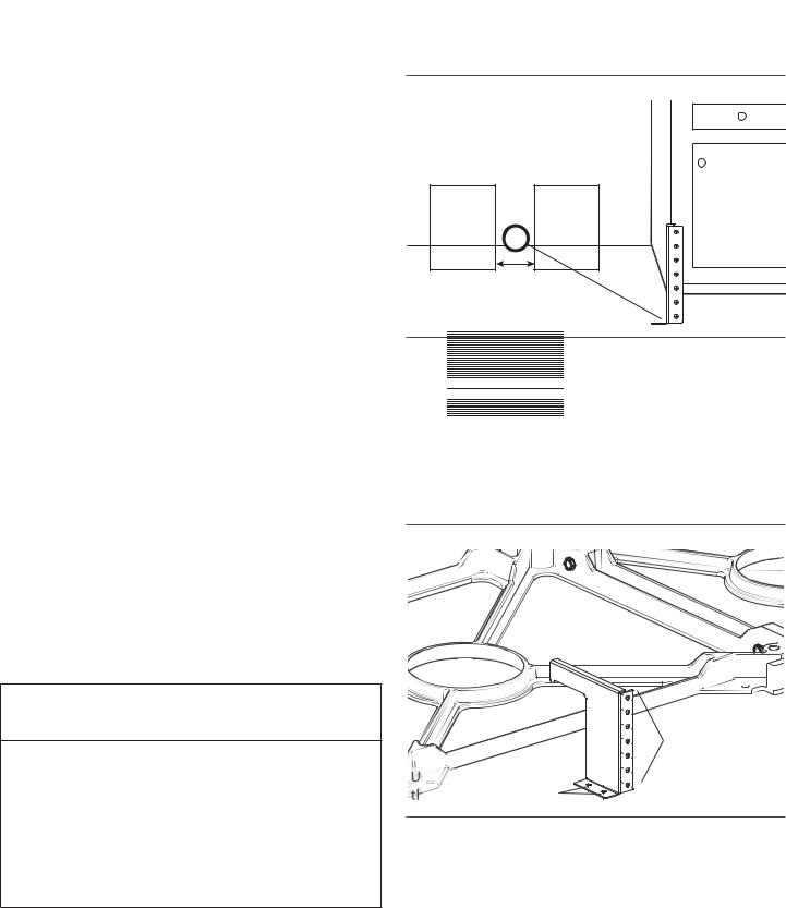
1.Place bracket on floor near the center of where the unit is to be finally located (Figure 13).
(/(&75,&$/ *$6 =21( =21(
´
PP
Figure 13: Anti-tip Bracket Mounting Location
2.Secure bracket into the wall stud using (2) mounting screws or drywall anchors, as appropriate (Figure 14).
3.Secure the bracket to the floor using the screws provided (Figure 14).
4.Later, when the unit is installed, the adjustable legs will allow the cast base to slide under the bracket hook, stabilizing the unit.
|
6TF TDSFXT UP |
|
TFDVSF UIF CSBDLFU |
|
UP UIF SFBS XBMM |
6TF TDSFXT UP TFDVSF |
TUVE |
UIF CSBDLFU UP UIF GMPPS |
|
|
Figure 14: Anti-tip Bracket |
5.If the range is moved to a new location, the Anti-Tip must be reinstalled.
English 13

Step 6: Gas Requirements and
Hookup
Verify the type of gas being used at the installation site.
The appliance is shipped from the factory for use with natural gas. It must be converted for use with propane. A qualified technician or installer must do the conversion. Make certain the range matches the type of gas available at this location.
NATURAL GAS REQUIREMENTS:
Inlet Connection: |
3/4” (19 mm) NPT external |
|
1/2” (12.7 mm) NPT internal |
|
(Minimum 3/4” dia. flex line.) |
|
|
Supply Pressure: |
6" min. to 14" max. water column. |
|
(14.9 to 34.9 mb) |
|
|
Manifold Pressure: |
5" water column (12.5 mb) |
|
|
PROPANE GAS REQUIREMENTS:
Inlet Connection: |
3/4” (19 mm) NPT external |
|
1/2” (12.7 mm) NPT internal |
|
(Minimum 3/4” dia. flex line.) |
|
|
Supply Pressure: |
11" min. to 14" max. water column. |
|
(27.4 mb to 34.9 mb) |
|
|
Manifold Pressure: |
10" water column (24.9 mb) |
|
|
Natural Gas Appliances - For installation of the appliance above 2000 ft (610 m), a High Altitude Conversion Kit (Service Number 746376) is available for purchase from Thermador Customer Service. It is required that a Certified Professional install the High Altitude Conversion Kit.
Propane (LP) Gas Appliances - NOTE: The appliance must first be converted for use with Propane (LP) Gas before it can be converted for use at high altitude. The Propane (LP) Conversion Kit (Service Number 553182) supplied with the appliance is required to be installed prior to converting for use at high altitude. This appliance has been CSA certified for safe operation up to an altitude of 2,000 ft (610 m) elevation above sea level. For installation of the appliance above 2,000 ft (610 m), a High Altitude Conversion Kit (Service Number 746376) is available for purchase from Thermador Customer Service. It is required that a Certified Professional install both the Propane (LP) Conversion Kit and the High Altitude Conversion Kit.
Hook Up
The gas supply connections shall be made by a competent technician and in accordance with local codes or ordinances. In the absence of local codes, the installation must conform to the National Fuel Gas Code ANSI Z223.1/ NFPA54current issue.
1.A manual gas shut-off valve (Figure 15) must be installed external to the appliance, in a location accessible from the front, for the purpose of shutting off the gas supply. The supply line must not interfere with the back of the unit. Make sure the gas supply is turned off at the manual shut-off valve before connecting the appliance.
•The range is supplied with its own pressure regulator that has been permanently mounted within the range body.
2.Locate the gas supply line connection at the back of the range (Figure 15).
3.Use a ¾” (19 mm) flex line to connect between the gas supply and the appliance gas inlet. The appliance gas inlet connection is ½” (13 mm) NPT (Figure 15).
•Use caution to avoid crimping the ¾” (19 mm) flex line when making bends.
•Suggested length of flex line is 48" (1219 mm); however, please check local codes for your area's requirements before installation.
 WARNING:
Gas line must not come in contact with any components inside back cover of range.
4.Use a pipe sealing compound or Teflon® tape on the pipe threads. Be careful not to apply excessive pressure when tightening the fittings.
5.Leak testing of the appliance shall be in accordance with the following instructions.
•Turn on gas and check supply line connections for leaks using a soap and water solution.
•Bubbles forming indicate a gas leak. Repair all leaks immediately after finding them.
 WARNING:
Do not use a flame of any kind to check for gas leaks.
English 14
The appliance and its individual shut off valve must be disconnected from the gas supply piping system during any pressure testing of the system at test pressures in excess of 1/2 psig (3.5kPa.).
When checking the manifold gas pressure, the inlet pressure to the regulator should be at least 6.0" W.C. (14.9 mb) for natural gas or 11.0" W.C. (27.4 mb) for propane. Do not attempt any adjustment of the pressure regulator.
Installer is responsible for ensuring that the installation, gas connections, and grounding comply with all applicable codes.
 CAUTION:
When connecting unit to propane gas, make certain the propane gas tank is equipped with its own high pressure regulator in addition to the pressure regulator supplied with the appliance. The pressure of the gas supplied to the appliance regulator must not exceed 14" water column (34.9 mb).
w (BT *OMFU |
w (BT *OMFU -PDBUJPO |
 3BOHF (BT *OMFU
|
|
"EBQUFS |
£w NN |
|
|
JG BQQMJDBCMF |
FYUFSOBM UISFBE |
|
|
|
w NN |
.BOVBM (BT |
"EBQUFS |
£w NN 'MFY MJOF |
JOUFSOBM UISFBE |
TIVU PGG WBMWF |
JG BQQMJDBCMF |
|
|
Figure 15: Gas Supply Connection
 CAUTION:
The appliance must be isolated from the gas supply piping system by closing its individual manual shut-off valve during any pressure testing of the gas supply piping system at test pressures equal to or less than 1/2 psig (3.5kPa.).
English 15

Step 7: Electrical Requirements, Connection & Grounding
MODEL |
VOLTAGE |
CIRCUIT |
FREQUENCY |
PHASE |
|
|
TYPE |
RATING |
|||||
|
|
|
|
|||
|
|
|
|
|
|
|
36” |
240/208 VAC |
40 Amps |
60 Hz. |
Single |
|
|
|
|
|
|
|
||
48" |
240/208 VAC |
50 Amps |
60 Hz. |
Single |
|
|
|
|
|
|
|
|
|
Table 3: Electrical Supply Circuit Requirements
Prior to servicing appliance, always disconnect appliance electrical supply cord, if so equipped, from wall receptacle. If appliance is hard-wired to power supply, disconnect power to unit by turning off the proper circuit breaker. Lock service panel to prevent power from being turned ON accidentally.
A neutral supply wire must be provided from the power source (breaker) because critical range components, including the surface burner spark re-ignition module,
require 120 VAC to operate safely and properly.
 WARNING:
An improper 120/ 240 VAC power supply will cause malfunction, damage to this appliance, and possibly create a condition of shock hazard.
If the correct power supply circuit is not provided, it is the responsibility and obligation of the installer and user to have proper power supply connected. This must be accomplished in accordance with all applicable local codes and ordinances by a qualified electrician. It is the responsibility of the installer to ensure compliance of local codes. In the absence of local codes and ordinances, the power supply connection shall be in accordance with the National Electric Code.
Observe all governing codes and ordinances when grounding. In the absence of these codes or ordinances observe National Electrical Code ANSI/NFPA No. 70 current issue. See the following information in this section for grounding method.
Electrical wiring diagrams and schematics have been placed behind the Door Trim of the range for access by a qualified service technician (see Figure 38 on page 27).
The ranges are to be connected to a 240/208 VAC power supply.
Dual Fuel models must be connected to the power supply utilizing one of the following methods. For all methods of connection, the length of the cord or conduit/wiring must allow the unit to be slid completely out of the cabinet without having to unplug or disconnect the unit from the power supply. Recommended minimum free length of cord or conduit is 4ft (1.2m). Electrical installations and grounding must be in accordance with all local codes and ordinances, and/or the National Electric Code, as applicable.
Permanent Connection (Hard Wiring)
Units may be hard wired to the power supply. The installer must provide approved flexible aluminum conduit, ¾”
(19 mm) trade size, maximum 6ft (1.8 m) long.
Locate the terminal block on the rear of the unit and remove cover (refer to Figure 16). The conduit must be installed to the terminal block using an approved conduit connector. The free end of the conduit must be connected to a terminal block provided in the electrical supply zone, as shown in Figure 4 on page 8.
Mount a strain relief (not provided) into the 1" (25.4 mm) diameter hole located below the terminal block (see Figure 16). Wiring for the unit is to be brought into the terminal block through the conduit and through the strain relief. The ends of the wiring must have 1/4” (6 mm) faston closed-loop lugs attached, preferably soldered in place. Make the connections to the terminal block provided.
If aluminum supply wiring exists in the installation, splice the aluminum house wiring with appropriate-thickness gauge copper wire for adapting to the range, using special connectors designed and certified for joining copper and aluminum wire. Follow the connector manufacturer’s recommended installation procedure.
 WARNING:
Improper connection of aluminum house wiring can result in a fire or shock hazard. Use only connectors designed and certified for connecting to aluminum wire.
English 16

4-Wire Connection
A unit must be connected to the power supply with a 3- POLE, 4-CONDUCTOR cord kit rated 125/250 VOLTS, 50 AMPERES, and marked for use with ranges.
The cord kit must be attached to the range terminal block with a strain relief (not provided) which will fit a 1" (25.4 mm) diameter hole. If not already equipped, the cord must also have 1/4” (6 mm) faston closed-loop lugs attached to the free ends of the individual conductors, preferably soldered in place.
1.Locate the terminal block on the rear of the unit and remove cover (see Figure 16).
2.Mount strain relief (not provided with range) into the 1" (25.4 mm) diameter hole in the back panel located below the terminal block. Route wires up through strain relief.
4.Secure the neutral, grounded wire of the supply circuit, to the center stud of the terminal block with nut (see
Figure 17).
5.Secure the L1 (red) and L2 (black) power leads to the outside terminal studs (brass colored) with nuts.
6.Remove green ground screw located beneath the terminal block. Discard white wire.
7.Secure the bare copper ground lead to the range chassis using the ground screw previously used for the white wire. Be sure that neutral and ground terminals do not touch.
8.Tighten all connections securely.
5FSNJOBM #MPDL
4USBJO 3FMJFG
Figure 16: Strain Relief Location
3.Remove upper nuts only from the terminal block studs. Do not remove lower nuts which secure range internal wiring leads.
|
|
%ODFN / |
|
:KLWH |
:LUH |
5HG / |
1HXWUDO :LUH |
|
:LUH
*UHHQ *URXQG :LUH
Figure 17: 4-Wire Connection
9. Reinstall the terminal block cover.
INSTALLER — show the owner the location of the circuit breaker. Mark it for easy reference.
English 17
3-Wire Lead Connection
Where local codes and ordinances permit grounding through neutral, and conversion of supply to 4 wire is impractical, unit may be connected to the power supply with a 3-POLE, 3-CONDUCTOR cord kit rated 125/250 VOLTS, 50 AMPERES, and marked for use with ranges.
The cord kit must be attached to the range back panel with a strain relief which will fit a 1" (25.4mm) diameter hole. If not already equipped, the cord must also have 1/4” (6mm) faston closed-loop lugs attached to the free ends of the individual conductors, preferably soldered in place.
1.Locate the terminal block on the rear of the unit and remove cover.
2.Mount strain relief (not provided with range) into the 1" (25.4 mm) diameter hole in the back panel located below the terminal block (see Figure 17). Route wires up through strain relief.
5FSNJOBM #MPDL
4USBJO 3FMJFG
Figure 18: Strain Relief Location
3.Remove upper nuts only from the terminal block studs. Do not remove nuts which secure range internal wiring leads.
4.Secure the neutral, grounded wire of the supply circuit, to the center stud (silver colored) of the terminal block (see Figure 19).
5.Secure the L1 (red) and L2 (black) power leads to the outside corresponding terminal block studs (brass colored).
6.Secure one end of the mounted looped neutral wire, located beneath terminal block, to the center stud of the terminal block with nut and keep the other end of the wire screwed into the back of the range.
7.Tighten nuts securely.
|
|
%ODFN / |
|
:KLWH |
:LUH |
5HG / |
1HXWUDO :LUH |
|
:LUH |
|
|
*URXQG  OLQN SURYLGHG
RQ UDQJH
Figure 19: 3-Wire Connection
8. Reinstall the Terminal Block Cover.
INSTALLER — show the owner the location of the circuit breaker. Mark it for easy reference.
English 18

Step 8: Backguard Installation
(optional)
Model |
Low Back |
High Shelf |
Flush Island |
|
Trim |
||||
|
|
|
||
|
|
|
|
|
36” |
PA36JLBG |
PA36JHSG |
Included with |
|
range |
||||
|
|
|
||
|
|
|
|
|
48” |
PA48JLBG |
PA48JHSG |
Included with |
|
range |
||||
|
|
|
||
|
|
|
|
|
48” |
PA48JLBSG |
PA48JHSSG |
Included with |
|
Steam |
range |
|||
|
|
|||
|
|
|
|
Table 4: Backguard Kit Model Numbers
Installation methods will vary upon need. Before you begin read these instructions carefully. Observe all local codes and ordinances.
Backsplash Installation
(PA [30, 36, 48] JBS)
Parts Included |
Tools Needed |
10 – 1” (25.4 mm) |
Phillips screwdriver or |
screws |
drill |
1 – Backsplash |
Tape measure |
1 – Installation Guide |
Pencil |
The Backsplash must be installed prior to installing an overhead hood given that the hood shell covers the top mounting screws of the Backsplash.
To protect against scratches, leave protective film on Backsplash until after installation is complete.
If range is already installed, refer to the manufacturer’s instructions to disconnect gas and power supplies. Move
range forward to gain access to rear of unit.
 WARNING:
To reduce the risk of fire or injury to persons, check to make sure all packaging has been removed from accessory devices before use.
1.Locate and lightly mark wall studs. Wall studs are usually installed with a 16” or 24” (406 or
1372 mm) space on center.
2.The height of the hood will determine the height of the top edge of the Backsplash. The Backsplash should be mounted so that the bottom rear edge of the hood overlaps the Backsplash 1½” (38 mm).
3.Per each wall stud, use (2) 1” (25.4 mm) Phillips head screws to secure both the top and bottom of the Backsplash (see Figure 20). Space screws evenly across top and bottom of Backsplash.
•Due to variable wall stud widths and varying Backsplash widths, in some cases only one wall stud may be found at the mounting location.
4.Remove protective plastic.
w BOE w
 BOE NN

w NN
Figure 20: Backsplash Installation
English 19

Installing a Backsplash with a Keep Hot Shelf
A hood can be installed first if the Backsplash is to be installed with a Keep Hot Shelf given that the Keep Hot
Shelf covers the top mounting screws of the Backsplash.
To protect against scratches, leave protective film on the Backsplash until after installation is complete.
If range is already installed, refer to the manufacturer’s instructions to disconnect gas and power supplies. Move
range forward to gain access to rear of unit.
1.Locate wall studs. Wall studs are usually installed with a 16” (406 mm) or 24” (1372 mm) space on center.
2.The height of the hood will determine the height of the top edge of the Backsplash. The Backsplash should be mounted so that the bottom rear edge of the Keep Hot Shelf overlaps the Backsplash 1½” (38 mm).
3.At the locations indicated in Figure 22, mount the lower shelf brackets included with the Keep Hot Shelf through the Backsplash and into the wall studs.
•Due to variable wall stud widths and varying Backsplash widths, in some cases, only one wall stud may be found at the mounting location.
4.Remove Backsplash protective covering.
5.Start with the Keep Hot Shelf Installation.
Figure 22: Backsplash with a Keep Hot Shelf
Figure 21: Backsplash with a Keep Hot Shelf
English 20
Keep Hot Shelf (KHS [30, 36, 42, 48] QS)
|
|
|
|
|
|
´ ´ ´ ´ |
|
PP |
|||
|
|
|
|
||
|
|
|
|
||
|
%DFNVSODVK |
|
|
|
|
|
&OLS 5DFN 7RS |
|
PP |
||
|
|
|
|
||
|
&OLS |
|
|
|
|
5DFN |
|
|
|
|
|
PP |
|
|
|
|
|
|
|
|
|
.HHS +RW |
|
|
|
|
5DFN |
||
|
|
PP |
|
||
PP |
|
|
|
|
|
PP |
|
|
|
|
|
PP
Figure 23: Keep Hot Shelf
Items Included
12 – 1” (25.4 mm) screws
4 – ½” (12.7 mm) screws
4 – U-Nuts
2 – Upper shelf brackets
4 – Lower shelf brackets
2 – Racks
1 – Wall Plate
1 – Installation guide & templates
|
Tools Needed |
|
|
|
|
Tape measure |
|
Phillips screwdriver or drill |
|
|
|
Painter’s Tape |
|
Sharp knife or scissors |
|
|
|
1.Tape the templates included with the Keep Hot Shelf to the wall accordingly:
•Tape the sheet titled Left Hand Template to bottom and left end of hood. Align the bottom line of hood with the top line of the template.
•Tape the sheet titled Right Hand Template to bottom and right end of hood. Align the bottom line of hood with the top line of the template.
•Tape the sheet titled Installation Instruction so that the arrow at the top of the template aligns with hood centerline. Align the bottom line of the hood with the top line of the template.
•Left to right sides of the template must be equal to length of shelf.
2.Mount the (2) upper shelf brackets and the (3) lower shelf brackets on the 30” & 36” models or (4) lower shelf brackets for the 48” model at the locations outlined on the templates. Secure with (10) 1”
(25.4 mm) screws provided.
3.Cut template out from around the brackets and remove from the wall. Do not discard template before the Keep Hot Shelf is completely installed.
4.Insert U-Nuts onto each of the lower shelf brackets.
5.Install the wall plate by setting the corner notches (back of wall plate) atop the (2) upper shelf brackets.
6.Slide the shelf upwards until the bottom engages with the lower shelf brackets (Figure 24).
6QQFS 4IFMG #SBDLFUT |
/PUDIFT |
-PXFS 4IFMG #SBDLFUT
Figure 24: 48” Back of Wall Plate
7.Check if the top is properly secured by pulling the top section of the shelf from the wall.
8.Secure to bottom of shelf with the (4) ½” (12.7 mm) screws provided.
English 21

Backguard Installation
When installing against a combustible surface, a High Shelf or Low Backguard is required. A THERMADOR® High Shelf or Low Backguard must be purchased separately.
See “Installation Clearances” on page 5.
When using the Flush Island Trim, THERMADOR recommends a minimum 12” (305 mm) rear clearance to a combustible surface (see Figure 1, Cabinet Clearances). Clearances from non-combustible materials are not part of the ANSI Z21.1 scope and are not certified by
CSA. Clearances of less than 12” (305 mm) must be approved by the local codes and/or by the local authority having jurisdiction.
NOTE:
If a Backsplash is to be used in addition to a backguard, install the Backsplash first and the backguard second
before sliding range into place.
High Shelf Parts Included
High Shelf top panel
 WARNING:
Fingers or hands could get pinched when installing the backguard. Severe injury could result. Use extreme caution and wear thick protective gloves to avoid potential laceration to finger or hand while sliding the backguard down onto the range.
 CAUTION:
The High Shelf can get very hot! DO NOT place the following items on top of the High Shelf:
•plastics or containers that can melt
•flammable items
•a total load over 30 pounds (13.6kg)
High Shelf front panel
)JHI 4IFMG  PS
PS
-PX #BDLHVBSE 
T-20 Torx stainless screws
T-20 Torx drill point screws
Installation Guide
Low Back Parts Included
Low Back panel
|
|
|
|
|
|
|
|
|
|
|
|
|
|
|
|
|
|
|
|
|
|
|
|
|
|
|
|
|
|
|
|
|
|
|
|
|
|
|
|
|
|
|
|
|
|
|
|
|
|
|
|
|
|
|
|
|
|
|
|
|
|
|
|
|
|
|
|
|
|
|
|
|
|
|
|
|
|
|
|
|
|
|
|
|
|
|
|
|
|
|
|
|
|
|
|
T-20 |
Torx stainless screws |
|
|
|
|
|
|
|
|
|
|
|
|
|
T-20 |
Torx drill point screws |
|
|
|
|
|
|
|
|
Figure 25: High Shelf & Low Back Front View |
|||||||||||||
|
|
|
|
|
|
|
|
|
|
|||||
Installation Guide
Tools Needed
T-20 Torx head screwdriver or drill
Protective Work Gloves
English 22

High Shelf Assembly
1.Remove protective plastic.
2.Slide the shelf onto the backguard panel.
2.Remove the (4) drill point screws securing the trim to the side panels, and the (3) or (4) drill point screws securing the piece to the back panel. Lift up to fully remove (Figure 28).
Figure 26: High Shelf Assembly
3.Install the included stainless screws along the topside of shelf and into the back of the shelf (Figure 26).
4.Begin with Backguard Installation.
Backguard Installation
1.Depending on model, remove the (3) or (5) T-20 Torx stainless screws in the front face of the included Flush Island Trim (Figure 27).
Figure 28: Flush Island Trim Rear Screw Removal
3.Align the back panel of the new accessory with the flanges on the range side panels right and left rear corners. The backguard is inserted inside the guide channels on the back of the range (Figure 29).
TJEF QBOFM GMBOHF |
|
Figure 29: Backguard Installation |
4. |
Make sure the backguard’s front face is outside the |
Figure 27: Flush Island Trim Front Face Screw Removal |
flange on the front side of the range. |
5. |
Re-install screws removed in Steps 1 and 2. |
English 23

Step 9: Placing and Leveling
the Range
Leveling Leg Adjustment
 CAUTION:
The top edges of the range’s side panels must be on the same or higher level as the adjacent countertop. If the range is operated while at a lower height relative to the adjacent cabinet, the cabinet could be exposed to excessive temperatures, causing damage to the cabinet and countertop (see Figure 32 on page 25).
For proper performance, the range must be level. This is especially important for all products that have the griddle feature. Priority should be placed on ensuring that the oven cavities are also level for optimum cooking performance.
The range has (4) leveling legs that are threaded into the cast aluminum base structure.
1.Measure the countertop heights first with a tape measure and add an additional 1/16” - 1/8” (2-3 mm). Adjust the legs accordingly prior to pushing the range back to its final location.
2.Rotate the legs using a 12” (305 mm) adjustable wrench on the flat sides of each foot.
Figure 30: Leveling Legs
3.Progression of the height adjustments should be alternated proportionally between the four corner legs, until the top edges of the range’s side panels are close to matching the counter top height.
4.Final height adjustments of the two rear legs take place before moving the range into its installed position in the cabinet.
5.Each range has a pair of casters adjacent to the rear legs (see Figure 31). The casters make moving the range easier by slightly lifting the front and allowing the casters to glide the range back towards its installed position.
 $BTUPST
Figure 31: Castor Locations
6.As the range is moved into its final, installed position, verify that the “hook” on the Anti-Tip Bracket is in a position to engage the back edge of the cast base (see
“Step 5: Installing Anti-Tip Device” on page 12). This can be verified by viewing through the opening near the floor.
7.With the range in the installed position, the final height adjustments are made to the two front legs to ensure proper alignment to the countertop.
English 24

$"65*0/ %0 /05 PQFSBUF SBOHF JG TJEFT BSF MPXFS UIBO UIF BEKBDFOU DBCJOFU 5IJT NBZ EBNBHF UIF DBCJOFU BOE DPVOUFS UPQ EVF UP FYDFTTJWF UFNQFSBUVSFT
$033&$5 -FWFMJOH MFHT TIPVME CF BEKVTUFE TP UIBU UIF SBOHF |
TJEFT BSF BU UIF TBNF PS IJHIFS MFWFM BT UIF BEKBDFOU DBCJOFU |
Figure 32: Adjusting the Height of the Range
English 25
Griddle Tilt Adjustment (not all models)
If the range is equipped with an electric griddle, check the griddle frame adjustment by pouring two tablespoons of water on the back of the griddle plate. The water should slowly roll into the grease tray. If not, adjust the two screws under the back of the frame. Start with one half turn counterclockwise (CCW) of the screws. Further adjustment should be made by one-quarter turn until water slowly flows
into the grease tray.
0RYH JULGGOH SODWH WR WKH  VLGH DQG WXUQ OHYHOLQJ VFUHZV
Figure 33: Griddle Leveling Screws
 WARNING:
To avoid risk of injury, never operate griddle without the griddle plate installed. Never use griddle in a manner that is not prescribed by the Use and Care Manual.
The griddle plate must always be in place when the griddle is turned on.
Installing the Leg Covers
1.Remove plastic coverings from the stainless steel covers.
2.Place the smaller cover, with cutouts facing up, inside the larger cover with the openings of both stacked and facing the back.
Figure 34: Leg Covers
3.Beneath the range, wrap the cover assembly around the leg.
4.Slide the outer cover up while the inner piece remains on the floor. The mating part has dimples for which the holes of the larger cover should seize. You should feel a definitive click, letting you know that the cover assembly has been mounted to the unit.
%JNQMFT
Figure 35: Range Dimples
English 26
 Loading...