


 Loading...
Installation |
|
G U I D E |
WD30WC WD30W SD30WC SDS30WC |
|
|
Masterpiece® and Professional Series |
|
Warming Drawer and Storage Drawer |
|
T H E R M A D O R . C O M

Table of
C O N T E N T S
9 Safety Definitions .................................................. |
3 |
IMPORTANT SAFETY INSTRUCTIONS ........................ |
4 |
Appliance Handling Safety ............................................. |
4 |
Safety Codes and Standards ........................................... |
4 |
Electric Safety ................................................................. |
4 |
Related Equipment Safety .............................................. |
5 |
State of California Proposition 65 Warnings: .................. |
5 |
Before you Begin ........................................................ |
6 |
Tools and Parts Needed .................................................. |
6 |
Parts Included ................................................................. |
6 |
Power Requirements and Grounding ............................. |
6 |
Prepare Installation Space .......................................... |
6 |
Cabinet and Cutout Information ..................................... |
6 |
Unit Dimensions SDS30WC ............................................ |
6 |
Unit and Cabinet Dimensions WD30W / WD30WC / |
|
SD30WC .......................................................................... |
6 |
Installation Procedure WD30WC, SD30WC ................ |
7 |
Removing Drawer from Housing .................................... |
8 |
Installing Drawer to Housing .......................................... |
8 |
Parts Included ............................................................... |
10 |
Installing with Microwave .............................................. |
10 |
Installation Procedure SDS30WC .............................. |
12 |
Removing Drawer from Housing .................................. |
13 |
Preparing the Storage Drawer for Installation .............. |
13 |
Remove Shipping Brackets ........................................... |
14 |
Install Steam Oven on Top of Storage Drawer ............. |
15 |
Installing Drawer to Housing ........................................ |
15 |
Installation Procedure WD30W ................................ |
17 |
Preparing the Custom Panel for Installation ................. |
17 |
Attaching the Custom Panel ......................................... |
18 |
Installation Final Check List ........................................... |
19 |
Service ...................................................................... |
20 |
Data Plate ..................................................................... |
20 |
Rating Label-WD30W AND WD30WC ......................... |
20 |
Model Number and FD Number .................................. |
20 |
THERMADOR® Support ........................................... |
21 |
Service ........................................................................... |
21 |
Parts and Accessories ................................................... |
21 |

9Safety Definitions
9WARNING
This indicates that death or serious injuries may occur as a result of non-observance of this warning.
9CAUTION
This indicates that minor or moderate injuries may occur as a result of non-observance of this warning.
NOTICE: This indicates that damage to the appliance or property may occur as a result of non-compliance with this advisory.
Note: This alerts you to important information and/or tips.
3

9 IMPORTANT SAFETY INSTRUCTIONS
READ AND SAVE THESE INSTRUCTIONS
IMPORTANT: SAVE THESE INSTRUCTIONS FOR THE LOCAL ELECTRICAL INSPECTOR’S USE.
INSTALLER: LEAVE THESE INSTRUCTIONS WITH THE UNIT FOR THE OWNER.
OWNER: PLEASE RETAIN THESE INSTRUCTIONS FOR FUTURE REFERENCE.
WARNING
When properly cared for, your new appliance has been designed to be safe and reliable. Read all instructions carefully before use. These precautions will reduce the risk of burns, electric shock, fire and injury to persons.
When using kitchen appliances, basic safety precautions must be followed including those in the following pages.
WARNING
Do not repair, replace or remove any part of the appliance unless specifically recommended in the manuals. Improper installation, service or maintenance can cause injury or property damage. Refer to this manual for guidance. All other servicing should be done by an authorized servicer.
Appliance Handling Safety
Hidden surfaces may have sharp edges. Use caution when reaching behind or under appliance.
Close supervision is necessary when any appliance is used by or near children.
Do not touch hot surfaces. Use handles or knobs.
The use of accessory attachments not recommended by the appliance manufacturer may cause injuries.
Do not use outdoors.
Do not place on or near a hot gas or electric burner or in a heated oven.
Do not use appliance for other than intended use.
Extreme caution must be used when moving an appliance containing hot oil or other hot liquids.
To reduce the risk of fire, do not locate any heating or cooking appliance beneath the appliance.
To reduce the risk of fire, do not mount unit over or near any portion of a heating or cooking appliance.
To reduce the risk of electric shock, do not mount over a sink.
To reduce the risk of fire, do not store anything directly on top of the appliance surface when the appliance is in operation.
To reduce the risk of fire, do not store anything in the warming drawer (such as groceries, bags, etc.) which could cause fire if the drawer is turned on.
Safety Codes and Standards
This appliance complies with the latest version of one or more of the following standards:
UL 1026 - Electric Household Cooking and Food Serving Appliances
CSA-C22.2 No. 64 - Household Cooking and LiquidHeating Appliances
It is the responsibility of the owner and the installer to determine if additional requirements and/or standards apply to specific installations.
Electric Safety
WARNING
Before you plug in an electrical cord or turn on power supply, make sure all controls are in the OFF position.
Do not let cord hang over edge of table or counter or touch hot surfaces.
Always attach plug to appliance first, then plug cord into wall outlet. To disconnect, turn any control to “off”, then remove plug from wall outlet.
Do not operate any appliance with a damaged cord or plug or after the appliance malfunctions or has been damaged in any manner. It is unsafe to operate any appliance with a damaged power cord or plug. If the appliance has been damaged or malfunctions, safely disconnect the appliance from the power supply, then immediately contact a qualified appliance technician to inspect the product.
To protect against electrical shock, do not immerse cord, plugs or other electrical parts in water or other liquid.
For appliances equipped with a cord and plug, do not cut or remove the ground prong. It must be plugged in to a matching grounding type receptacle to avoid electrical shock. If there is any doubt as to whether the wall receptacle is properly grounded, the customer should have it checked by a qualified electrician. DO NOT use an adaptor or extension cord.
4

9 IMPORTANT SAFETY INSTRUCTIONS
READ AND SAVE THESE INSTRUCTIONS
If required by the National Electrical Code (or Canadian Electrical Code), this appliance must be installed on a separate branch circuit.
Installer-show the owner the location of the circuit breaker or fuse. Mark it for easy reference.
WARNING
Before installing, turn power OFF at the service panel. Lock service panel to prevent power from being turned ON accidentally.
Refer to data plate for more information. See “Data Plate” under Service for data plate location.
Be sure your appliance is properly installed and grounded by a qualified technician. Installation, electrical connections and grounding must comply with all applicable codes.
Related Equipment Safety
Remove all tape and packaging before using the appliance. Discard or recycle packaging materials according to local codes after unpacking the appliance.
Never modify or alter the construction of the appliance. For example, do not remove panels or covers.
CAUTION
For units with glass panels, use care when handling glass to avoid breaking. Broken glass could cause a laceration type injury.
CAUTION
It is recommended to have two (2) installers to install the unit assembly. Failure to do so may result in property damage or personal injury.
IMPORTANT SAFETY NOTICE: The California Safe Drinking and Toxic Enforcement Act requires the Governor of California to publish a list of substances known to the state to cause cancer, birth defects or other reproductive harm, and requires businesses to warn customers of potential exposure to such substances.
Save these instructions.
State of California Proposition 65
Warnings:
WARNING
This product can expose you to chemicals including vinyl chloride, which is known to the State of California to cause cancer and birth defects or other reproductive harm. For more information go to
www.P65Warnings.ca.gov.
5
Before you Begin
Tools and Parts Needed
T-20 star head screwdriver
Measuring tape
Drill with bit (1/8”)
Parts Included
T-20 star head screws, #8 x 1/2” (6)
Power Requirements and Grounding
Circuit Specifications: 120V, 15A, 60Hz
The outlet must be properly grounded in accordance with all applicable codes.
It is the responsibility of the installer to comply with local codes. If no local codes are applicable, wire in accordance with the National Electric Code, ANSI/NFPA 70-latest edition.
Prepare Installation Space
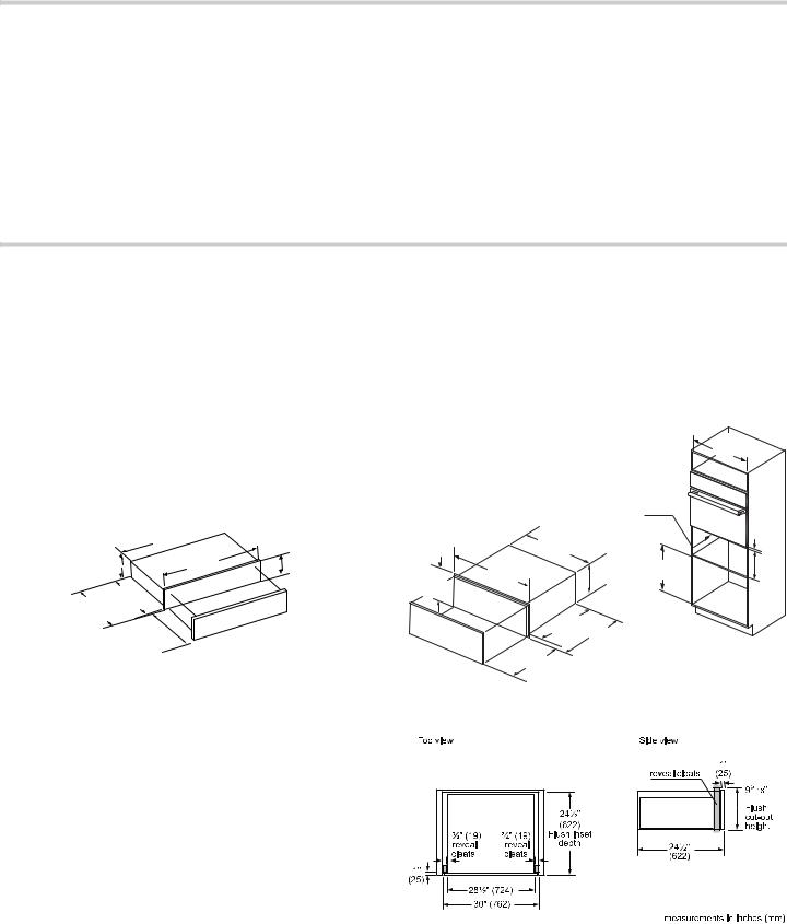
Cabinet and Cutout Information
Instructions are based on standard (in the U.S.A.) cabinets 36” (914 mm) high and 24” (609 mm) deep with a 25” (635 mm) countertop. If using non-standard cabinets, alter dimensions accordingly.
Unit Dimensions SDS30WC
Maximum weight capacity for the storage drawer is 40 pounds (18 kg).
 PP
PP
|
|
|
PP |
PP |
PP |
ò |
|
|
ò PP |
|
|
PP |
|
|
ô
PP
PP
Note: The dimensional drawing is for reference only. Refer to the installation guide included in the steam oven for unit and cabinet dimensions.
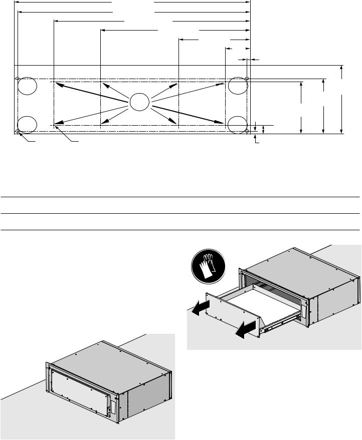
Unit and Cabinet Dimensions WD30W / WD30WC / SD30WC
Note: Power cord for the warming drawer units is 84” (2134mm) long.
Cabinet opening bottom must be able to support 110 pounds (50 kg).
|
|
|
|
|
|
|
|
|
|
|
|
|
|
|
|
|
|
|
|
|
|
|
|
|
|
|
|
|
|
|
|
|
|
|
|
|
|
||
|
|
|
|
|
|
|
|
|
|
|
|
|
|
|
|
|
|
|
|
|
|
|
|
|
|
|
|
|
|
|
|
|
|
|
|
0HDVXUHPHQWV LQ LQFKHV PP |
|
||
Flush Installation
6

Wall Mounted Installation
Thermador® warming drawers may be installed below any Thermador® single or double built-in oven. A minimum space of 1” (25.4mm) is recommended between the bottom of the oven and the top of the warming drawer.
Under Counter Installation
Thermador® warming drawers may also be installed below any Thermador® electric or non-Professional Series gas cooktop as long as there is not contact between the bottom of the cooktop and the top of the warming drawer. When installing below a Thermador® induction cooktop, a minimum 1” (25.4mm) air gap must be maintained between the bottom of the cooktop and the top of the warming drawer.
When installing below a Thermador Professional® rangetop, a minimum 2 3/4” (70mm) air gap must be maintained between the bottom of the rangetop and the top of the warming drawer.
Installation Procedure WD30WC, SD30WC
The electrical outlet can be installed in the back wall directly behind the warming drawer. A recessed power receptacle must not exceed 5 1/2 ft. (1.7m) maximum distance from either side of the warming drawer cutout. Installation clearances permit for the excess power cord to be coiled behind the appliance.
DO NOT install this warming drawer in wet locations or outdoors.
9WARNING
Do not repair, replace or remove any part of the appliance unless specifically recommended in the manuals. Improper installation, service or maintenance can cause injury or property damage. Refer to this manual for guidance. All other servicing should be done by an authorized servicer.
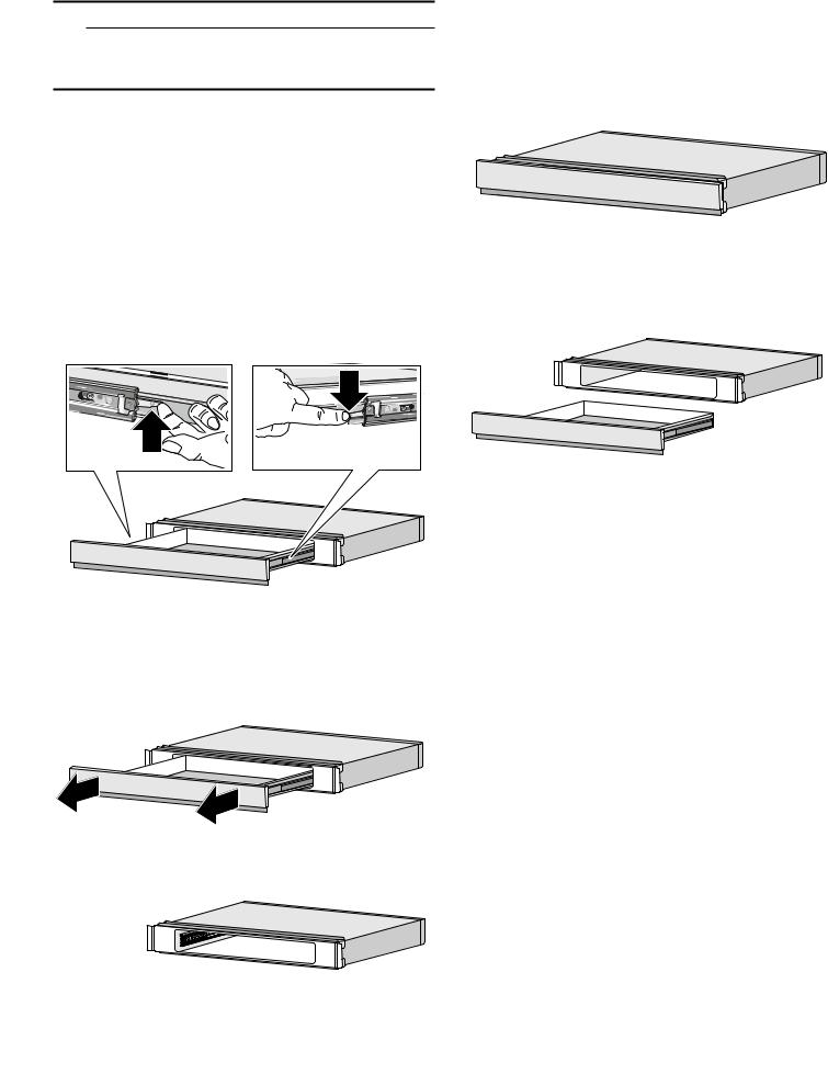
NOTICE: This unit utilizes a special ball bearing slide and locking feature called “Push to Open” (PTO). This feature allows for a design without a handle and a flush installation option.
There are two PTO slide assemblies installed in this unit, one on each side. A slide is mounted to each side of the housing and corresponding rails are mounted to each side of the drawer. (Only one side is shown in picture for clarity).
During installation or service (cleaning) it may be desired or recommended to remove the drawer from the unit to simplify or aid in installation or service. Special care and specific steps are recommended to ensure no damage is done to the PTO mechanism.
9CAUTION
Before installing, turn power OFF at the service panel. Lock service panel to prevent power from being turned ON accidentally.
7
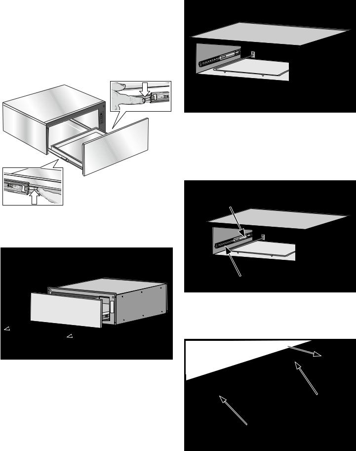
Removing Drawer from Housing |
3. Install or service (clean) housing with drawer removed. |
|
NOTICE: The following is the manufacturer’s |
|
|
recommendations for removing and installing the drawer |
|
|
to minimize the risk of damage to the PTO mechanism. |
|
|
1. Remove the drawer from the drawer housing. |
|
|
|
Ensure drawer is at full open position. |
|
|
Press down right drawer release lever. |
|
|
Lift up left drawer release lever. |
|
|
Firmly pull the drawer straight out. |
|
|
Retract cabinet rails while drawer is removed. |
|
2.Grasp both sides of the drawer and pulling straight and level, carefully remove the drawer housing. This step may require light to moderate force to completely remove drawer.
Installing Drawer to Housing
The slides mounted to each side of the housing wall have two moving components, an inner rail and a ball bearing carrier which need to be in the proper orientation for accurate installation and alignment.
There is also a visible locking mechanism located at the rear of each slide.
6OLGH ,QQHU 5DLO
%DOO %HDULQJ &DUULHU
Note: The housing of your warming drawer should match the image below identically before starting your installation. The ball bearing carrier should be locked in to the inner rail’s black plastic rail tip at the front of the inner rail.
/RFNLQJ 0HFKDQLVP
6OLGH ,QQHU 5DLO
%DOO %HDULQJ &DUULHU
8
1.With the drawer removed, set the slide inner rail to the drawer locked position by pushing the slide inner rail toward the rear of the housing until it locks in place.
-PDLJOH .FDIBOJTN
4MJEF *OOFS 3BJM
Notes
A slight side-to-side wiggle motion may be required to properly get the ball bearings to accurately align.
Remember: You are attempting to align two sets of ball bearings at this point. If more than a moderate force is required to insert the drawer at this time, remove the drawer and repeat the installation procedure to this point.
3.Continue to insert the drawer keeping the drawer level and square to the housing until a slight increase in resistance is felt at the approximate position shown below.
Note: A moderate force pushing on the black plastic ball carrier locking mechanism is required to set the slide to the drawer locked position. The drawer is locked when it remains in place and does not spring back to the open position.
4MJEF *OOFS 3BJM JT JO MPDLFE QPTJUJPO
2.Position the drawer assembly in front of the housing assembly and align the rail (plastic rail tip) to the slide ball carrier assembly. Keeping the drawer assembly level and square to the housing, gently insert the drawer to the housing assembly.
NOTICES
At this position, a slight increase in closure force is required with several small increments of force applied to the drawer to accurately align and set the drawer for proper operation.
An audible “click” should be heard when the drawer is properly closed causing the drawer to lock in the closed position.
9
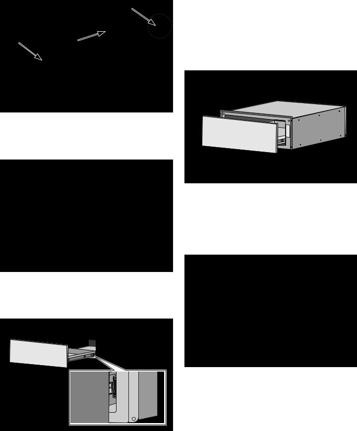
4.Test the operation of the PTO drawer by pushing on the center lower portion of the drawer front (optimum location for function).
Note: It should be noted the recommended and optimum location for opening the drawer is the lower center front. The drawer will operate with an opening force applied to any location on the drawer front, however a slight increase in opening force may be required.
Parts Included
Note: The parts contained in the square tube parts box are for microwave installations.
Installing with Microwave
1.Position the warming drawer housing in front of the cabinet where it is to be installed.
2.Position the microwave or steam oven nearby.
3.The warming drawer is ready for the microwave to be mounted.
Pre-Assembly Preparation
Mounting the microwave on the warming drawer requires the units to be assembled together prior to installing into the cabinet cutout.
The 30” warming drawer is combinable with 30” built in microwave/speed ovens. It is not combinable with the trim kit microwaves or 27” microwaves.
Parts Provided
Universal connector bracket (2) (in parts box).
Screws (16) (in red bag, inside parts box).
Mounting the Microwave on the Warming Drawer
Note: Do not place the warming drawer into the wall cabinet until after mounting the microwave on it using the universal connector brackets.
Note: The universal connector brackets are interchangeable for the left and right sides of the warming drawer. Be sure the taller vertical edge of the bracket is positioned to the outside of the warming drawer.
Assemble the Brackets to the Warming Drawer
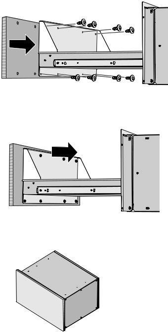
1.Attach both universal connector brackets to the warming drawer housing using three of the screws provided for each bracket (A). Tighten screws securely, but do not over tighten.
$
@ |
|
Note: The existing screws in the microwave base help with alignment. When lowering the microwave into place on the universal connector bracket allow these screw heads to slide into the slots as shown in the illustration below. The screw nearest the front of the microwave slides into the base of the slope at the font of the bracket.
10
Place the microwave oven unit on top of the universal connector brackets and fasten in place using three screws per side in the outside set of holes. Tighten the screws securely, but do not over tighten.
2.Continue with the unit installation in the section below describing installation of the warming drawer microwave/steam oven unit into the wall cabinet.
Installation into the Cabinet Cutout
1.Install the warming drawer and microwave assembly into the cabinet cutout.
9CAUTION
It is recommended to have 2 installers to install the unit assembly. Failure to do so may result in property damage or personal injury.
Slide the assembly into the cabinet cutout until it is flush with the front of the cabinet.
Secure through screw holes in cleats (drill pilot holes in cleats first if necessary). See installation dimensions diagram. Secure microwave according to installation instructions provided with those units.
2.Replace drawer.
Be sure cabinet rails are pushed inside cabinet.
Align the rails on the drawer rails with the rails attached to the drawer housing.
Firmly push the drawer straight into the drawer housing until the drawer clicks into place. The drawer should insert easily. If it binds, do not attempt to force it. Remove the drawer, align the slides on the housing to the front edge of the housing and try again. Slide the drawer into both housing slides at the same time, and keep the drawer level while doing so.
The drawer has a “push-to-open” operation. Pressing the front of the drawer inward causes the drawer to self open.
Open and close drawer to test operation.
Note: If the drawer will not close, verify that the rails release levers are properly positioned.
3.Turn power on at the service panel.
4.Test the installation.
Turn the warming drawer on. Signal light and timer should turn on immediately.
Check for warmth.
11

Installation Procedure SDS30WC
The SDS30WC storage drawer is specifically designed to only be used with the single steam ovens MEDS301WS and PODS301W.
Notes
The cutout dimensions in this manual for the SDS30WC are for reference only. For complete unit and cabinet dimensions refer to the installation guide included with the steam oven.
The storage drawer combined with the steam oven allows for the replacement of a standard single wall oven.
The steam oven is shorter than a standard wall oven. The storage drawer when combined with the steam oven allows for a direct replacement of a standard wall oven.
The drawer is functional storage drawer for the trays and racks supplied with the steam oven.
9WARNING
Do not repair, replace or remove any part of the appliance unless specifically recommended in the manuals. Improper installation, service or maintenance can cause injury or property damage. Refer to this manual for guidance. All other servicing should be done by an authorized servicer.
NOTICE: This unit utilizes a special ball bearing slide and locking feature called “Push to Open” (PTO). This feature allows for a design without a handle and a flush installation option.
There are two PTO slide assemblies installed in this unit, one on each side. A slide is mounted to each side of the housing and corresponding rails are mounted to each side of the drawer. (Only one side is shown in picture for clarity).
$
%
ASlide
BRail
During installation or service (cleaning) it may be desired or recommended to remove the drawer from the unit to simplify or aid in installation or service. Special care and specific steps are recommended to ensure no damage is done to the PTO mechanism.
12
Removing Drawer from Housing
9CAUTION
Hidden surfaces may have sharp edges. Use caution when reaching into, around or under appliance
NOTICE: The following is the manufacturer’s recommendations for removing and installing the drawer to minimize the risk of damage to the PTO mechanism.
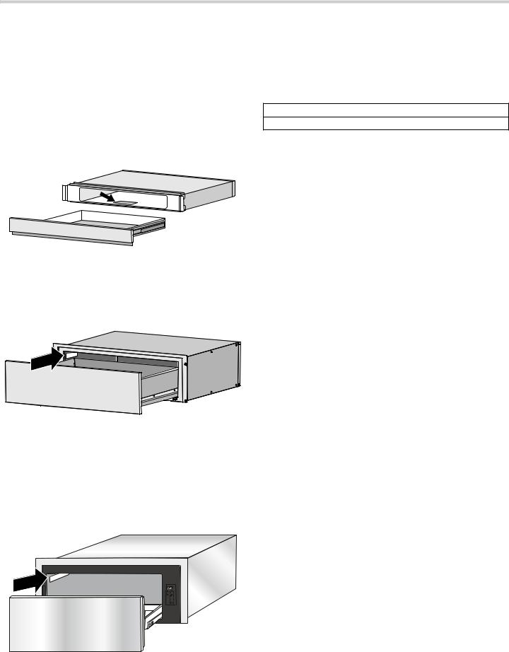
1.Remove the drawer from the drawer housing.
Activate the PTO feature by pushing on the front of the drawer face. Drawer will open approximately 4 inches.
Pull drawer to fully open position.
Press down right drawer release lever.
Lift up left drawer release lever.
Firmly pull the drawer straight out.
Retract cabinet rails while drawer is removed.
2.Grasp both sides of the drawer and pulling straight and level, carefully remove the drawer housing. This step may require light to moderate force to completely remove drawer.
3. Install or service (clean) housing with drawer removed.
Preparing the Storage Drawer for Installation
Remove the storage drawer from the packaging and place on a sturdy surface such as a table or workbench. Take precautions to protect the work surface while preparing the storage drawer for installation. The cardboard packaging or some other suitable protector could be used for this purpose.
Once appliance is properly placed on a prepared work surface, remove the drawer from the unit. Lay the drawer to the side taking care to protect the stainless steel surfaces from damage.
13
Remove Shipping Brackets
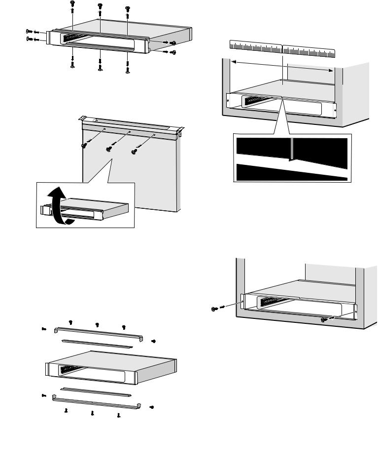
Remove the ten (10) screws fastening the shipping brackets from the housing.
The lower bracket screws can be accessed by turning the housing on end or sliding forward off the surface table to gain access to the lower screws and bracket.
A moderate force may be required to pry the top and bottom outer bracket from the side of the housing since the screws tend to slightly deform the housing hole causing slight binding of the bracket.
Note: Take care not to damage or scratch the front stainless steel cover or side trims.
Discard the two outer and inner shipping brackets and the ten (10) screws that were just removed. They are no longer needed for the installation.
Slide the housing into the cabinet opening until the side trims touch the cabinet face. There is a v-notch on the top face of the stainless steel front cover to assist in alignment of the housing to the cabinet opening. Measure the cabinet opening and adjust the storage drawer housing by aligning the v-notch with half of the measured cabinet opening. This will ensure the housing is centered in the opening.
Once the storage drawer has been aligned to the cabinet opening, install two (2) supplied screws to secure the housing to the cabinet face.
With the drawer fully open, drill pilot holes through side flange with a 1/8” (3.175mm) wood bit before the steam oven or drawer is installed.
14
Install Steam Oven on Top of Storage Drawer
Note: Installing the drawer before installing steam oven may scratch drawer face.
The steam oven must be installed on top of the storage drawer prior to reinstalling the drawer into the storage drawer housing. Slide steam oven directly on top of the storage drawer housing until it is flush with the cabinet.
Installing Drawer to Housing
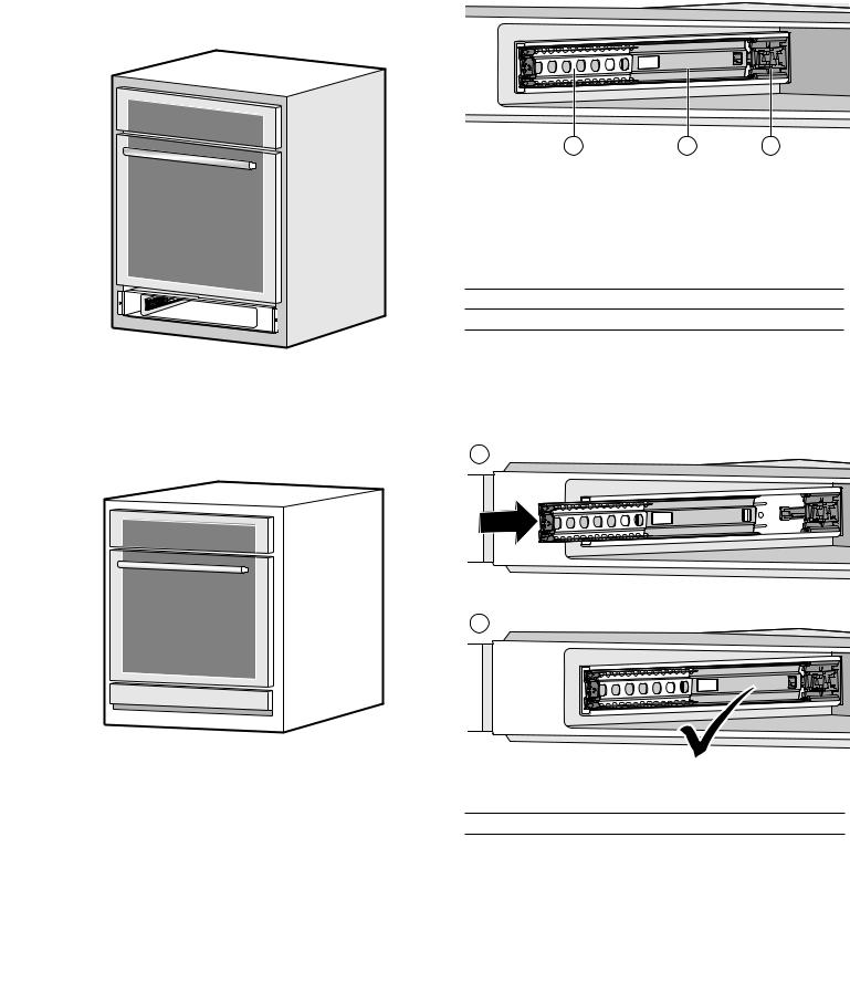
The slides mounted to each side of the housing wall have two moving components, an inner rail and a ball bearing carrier which need to be in the proper orientation for accurate installation and alignment.
Refer to the unit installation guide accompanying the steam oven for detailed installation instructions.
Reinstall the drawer to the storage drawer housing.
$ |
% |
& |
There is also a visible locking mechanism located at the rear of each slide.
ABall Bearing Carrier
BSlide Inner Rail
CLocking Mechanism
1.The slide inner rail should be set to the drawer locked position for proper installation. With the drawer removed push the slide inner rail toward the rear of the housing until it locks in place and does not spring back to the open position.
$
%
ASlide Inner Rail
BLocking Mechanism
Note: A moderate force pushing on the black plastic ball carrier locking mechanism is required to set the slide to the drawer locked position. The drawer is locked when it remains in place and does not spring back to the open position.
15

2.Position the drawer assembly in front of the housing assembly and align the rail to the slide ball carrier assembly. Keeping the drawer assembly level and square to the housing, gently insert the drawer to the housing assembly.
4.Test the operation of the PTO drawer by pushing on the center lower portion of the drawer front (optimum location for function). The drawer will operate with an opening force applied to any location of the drawer front when outside the recommended location with a slight increase in force.
$
Notes
A slight side-to-side wiggle motion may be required to properly get the ball bearings to accurately align.
Remember: You are attempting to align two sets of ball bearings. If more than a moderate force is required to insert the drawer at this time, remove the drawer and repeat the installation procedure to this point.
3.Continue to insert the drawer keeping the drawer level and square to the housing until a slight increase in resistance is felt at the approximate position shown below.
NOTICES
At this position, a slight increase in closure force is required with several small increments of force applied to the drawer to accurately align and set the drawer for proper operation.
An audible “click” will be heard when the drawer is properly closed causing the drawer to lock in the closed position.
16
Installation Procedure WD30W
9CAUTION
Never operate the warming drawer without a front panel attached. You can attach a Thermador® front panel or a custom front panel.
9CAUTION
DO NOT lift the warming drawer by the door’s handle as this may damage the slides and cause the door to fit incorrectly.
9WARNING
DO NOT REPAIR OR REPLACE PARTS
Do not repair or replace any part of the appliance unless specifically recommended in the manual. Improper installation, service or maintenance can cause injury or property damage. Refer to this manual for guidance. All other servicing should be done by an authorized servicer.
The electrical outlet can be installed in the back wall directly behind the warming drawer. A recessed power receptacle must not exceed 5 1/2 ft. (1.7m) maximum distance from either side of the warming drawer cutout. Installation clearances permit for the excess power cord to be coiled behind the appliance.
DO NOT install this warming drawer in wet locations or outdoors.
9CAUTION
Before installing, turn power OFF at the service panel. Lock service panel to prevent power from being turned ON accidentally.
Preparing the Custom Panel for Installation
Custom panels must meet the following requirements:
Custom panel is provided by the customer.
Have a handle provided by the customer.
Have a minimum thickness of 3/4” (19 mm).
Have all edges finished.
If using wood, the back must be sealed to prevent moisture damage.
Be capable of withstanding temperatures above 158°F (70°C).
Custom Panel Front Preparation
1.Mark pilot holes based on the dimensions in the template diagram below.
2.When drilling pilot and clearance holes, be careful not to drill all the way through the panel. Pilot holes should only be 10mm (7/16”) deep.
3.Dimensions are in millimeters (inches).
4.It is recommended to attach the desired handle/knob using metal fasteners.
17
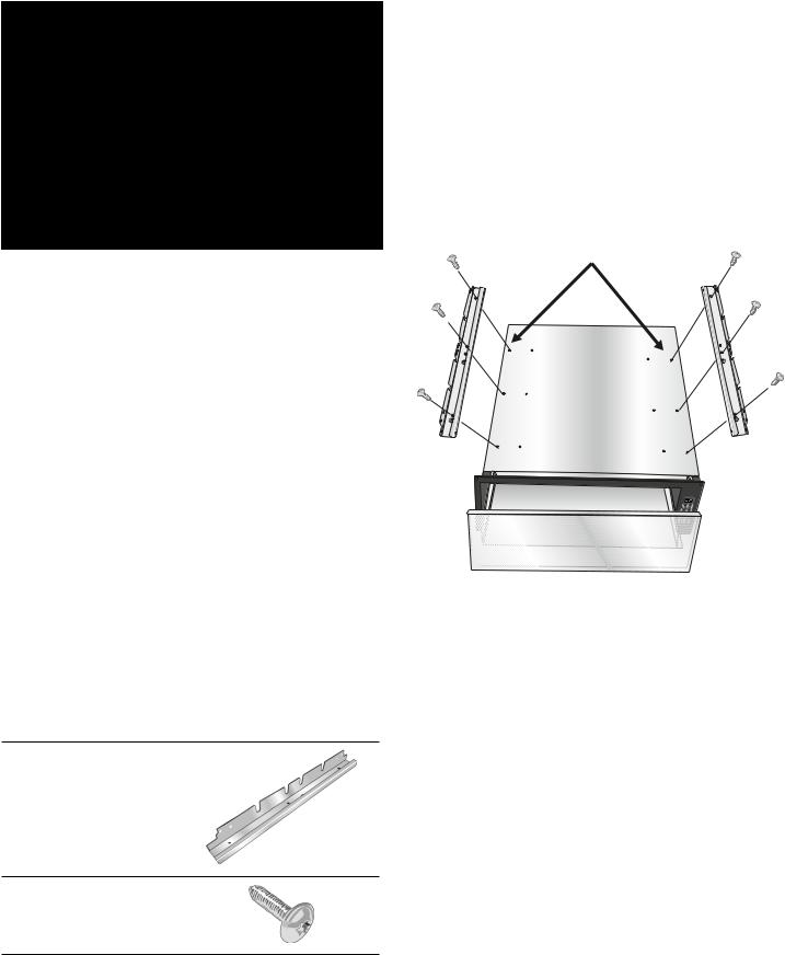
Attaching the Custom Panel
The custom front warming drawer comes with an attachment plate pre-assembled to the unit.
|
ë |
|
|
|
|
çʨʚ |
|
|
|
|
èçʨʓʘ |
|
|
|
|
ʎʨʚ |
|
|
|
|
|
|
|
|
|
|
èʨʚ |
|
|
|
|
|
|
|
|
|
|
çʨʚ |
|
$ |
|
$ |
ê |
|
|
|
|||
|
% |
|
èèʨʓʘ |
|
|
|
|
|
|
|
|
é |
|
|
$ |
|
$ |
|
|
|
èçʨʓʘ |
|
||
[ |
[ |
|
çʨʚ |
|
çʨʚ |
èʨʓʘ |
|
|
PP |
Note: Template dimensions are for reference only. The panel size is at the customer’s discretion.
Location Qty. Description
A4 Counter bore holes 10mm (7/16”) to clear mounting screws (not provided). Depth of bore hole is also 10mm (7/16”). Be careful not to drill through the panel.
B8 Pre-drilled to fit mounting screws 2.3mm (1/8”) provided (self-tap screw 8 x 1/2 T20 Truss). Depth of bore hole is 10mm (7/16”). Be careful not to drill through the panel.
Notes
The maximum panel weight is 8 pounds (3.6kg).
Panel thickness is 19.05mm (3/4”) based on U.S. standard cabinet thickness.
It is recommended that metal fasteners be used. Dimensions are in millimeters (mm).
Pre-drill pilot and clearance holes in the custom front panel as explained in the Installation Procedure chapter and then proceed as follows.
Open the drawer fully by grasping the outer edges of the attachment plate. Be sure to wear gloves to protect from cuts from the edges of the attachment plate.
18
Secure the custom panel to the drawer front with eight
(8) #8 x 1/2” T-20 star head screws supplied with the unit. Tighten the screws but do not overtighten.
Close the drawer. The installation of the custom panel to the attachment plate is complete.
Continue with the cabinet installation as described in the
Installation Procedure chapter.
Installation Final Check List
Specified clearances maintained to cabinet surfaces. Drawer handle is level and centered.
Drawer opens and closes properly. Unit is level.
All packaging material is removed.
Receptacle with correct over-current protection is provided for service cord connection.
Proper ground connection.
Owner is aware of location of the main circuit breaker.
19
Service
If the warming drawer elements or signal lights do not turn on, check the power source to see if the circuit breaker is tripped.
Data Plate
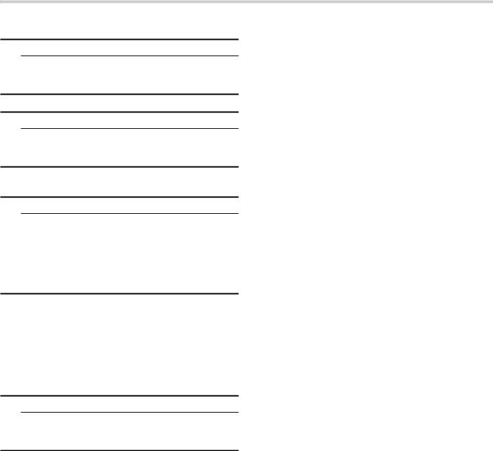
Model SDS30WC
Refer to the data plate on the storage drawer when requesting service or when contacting Customer Service for assistance. The data plate is visible on the bottom of the drawer casing for the SDS30WC storage drawer. It will be necessary to remove the drawer to view it.
SDS30WC Data Plate Location
The data plate for the SD30WC storage drawer is located on the left inside of the housing.
SD30WC Data Plate Location
Rating Label-WD30W AND WD30WC
Models SD30WC, WD30WC, WD30W
Refer to the rating label on the appliance when requesting service or when contacting Customer Service for assistance. The rating label is visible on the left of the drawer casing.
Model Number and FD Number
The model number and the FD number of your appliance are found on the data plate or rating label. Make a note of these numbers in the space below to save time in the event your appliance requires service.
Model # |
FD # |
Thermador Customer Support |
800-735-4328 |
Keep your invoice or escrow papers for warranty validation if service is needed.
20
Loading...