


2

Contents |
|
|
Before you Begin . . . . . . . . . . . . . . . . . . . . . . . . . . . . . . . . . . . . . . . . . . . . . . . . . . . . . . . . . . . . . . . . . . . . . . . . . . . |
5 |
|
Definitions . . . . . . . . . . . . . . . . . . . . . . . . . . . . . . . . . . . . . . . . . . . . . . . . . . . . . . . . . . . . . . . . . . . . . . . . . . . . . . . |
5 |
|
Important information . . . . . . . . . . . . . . . . . . . . . . . . . . . . . . . . . . . . . . . . . . . . . . . . . . . . . . . . . . . . . . . . . . . . . . |
5 |
|
Installation options . . . . . . . . . . . . . . . . . . . . . . . . . . . . . . . . . . . . . . . . . . . . . . . . . . . . . . . . . . . . . . . . . . . . . . . . . . |
6 |
|
Individual unit . . . . . . . . . . . . . . . . . . . . . . . . . . . . . . . . . . . . . . . . . . . . . . . . . . . . . . . . . . . . . . . . . . . . . . . . . . . . . |
6 |
|
Side by Side . . . . . . . . . . . . . . . . . . . . . . . . . . . . . . . . . . . . . . . . . . . . . . . . . . . . . . . . . . . . . . . . . . . . . . . . . . . . . |
6 |
|
Individual appliances with partition . . . . . . . . . . . . . . . . . . . . . . . . . . . . . . . . . . . . . . . . . . . . . . . . . . . . . . . . . . . |
6 |
|
At the end of the kitchen units . . . . . . . . . . . . . . . . . . . . . . . . . . . . . . . . . . . . . . . . . . . . . . . . . . . . . . . . . . . . . . . |
6 |
|
Installation location . . . . . . . . . . . . . . . . . . . . . . . . . . . . . . . . . . . . . . . . . . . . . . . . . . . . . . . . . . . . . . . . . . . . . . . . . |
7 |
|
Installation room . . . . . . . . . . . . . . . . . . . . . . . . . . . . . . . . . . . . . . . . . . . . . . . . . . . . . . . . . . . . . . . . . . . . . . . . . . |
7 |
|
Installation cavity . . . . . . . . . . . . . . . . . . . . . . . . . . . . . . . . . . . . . . . . . . . . . . . . . . . . . . . . . . . . . . . . . . . . . . . . . . |
7 |
|
Furniture/fixtures . . . . . . . . . . . . . . . . . . . . . . . . . . . . . . . . . . . . . . . . . . . . . . . . . . . . . . . . . . . . . . . . . . . . . . . . . . |
7 |
|
Base . . . . . . . . . . . . . . . . . . . . . . . . . . . . . . . . . . . . . . . . . . . . . . . . . . . . . . . . . . . . . . . . . . . . . . . . . . . . . . . . . . . . |
7 |
|
Connecting the power . . . . . . . . . . . . . . . . . . . . . . . . . . . . . . . . . . . . . . . . . . . . . . . . . . . . . . . . . . . . . . . . . . . . . . . |
8 |
|
Additional grounding procedure . . . . . . . . . . . . . . . . . . . . . . . . . . . . . . . . . . . . . . . . . . . . . . . . . . . . . . . . . . . . . |
8 |
|
Grounding instruction . . . . . . . . . . . . . . . . . . . . . . . . . . . . . . . . . . . . . . . . . . . . . . . . . . . . . . . . . . . . . . . . . . . . . . |
8 |
|
Connecting the water . . . . . . . . . . . . . . . . . . . . . . . . . . . . . . . . . . . . . . . . . . . . . . . . . . . . . . . . . . . . . . . . . . . . . . . |
8 |
|
Installation dimensions . . . . . . . . . . . . . . . . . . . . . . . . . . . . . . . . . . . . . . . . . . . . . . . . . . . . . . . . . . . . . . . . . . . . . . |
9 |
|
Single installation . . . . . . . . . . . . . . . . . . . . . . . . . . . . . . . . . . . . . . . . . . . . . . . . . . . . . . . . . . . . . . . . . . . . . . . . . . |
9 |
|
Side by Side installation . . . . . . . . . . . . . . . . . . . . . . . . . . . . . . . . . . . . . . . . . . . . . . . . . . . . . . . . . . . . . . . . . . . . |
10 |
|
Water connection . . . . . . . . . . . . . . . . . . . . . . . . . . . . . . . . . . . . . . . . . . . . . . . . . . . . . . . . . . . . . . . . . . . . . . . . . |
11 |
|
Appliance dimensions . . . . . . . . . . . . . . . . . . . . . . . . . . . . . . . . . . . . . . . . . . . . . . . . . . . . . . . . . . . . . . . . . . . . . . . |
12 |
|
1. |
18" Appliance (Freezer/Freezer with Ice and Water dispenser) . . . . . . . . . . . . . . . . . . . . . . . . . . . . . . . . . |
12 |
2. |
18" Appliance (Wine unit) . . . . . . . . . . . . . . . . . . . . . . . . . . . . . . . . . . . . . . . . . . . . . . . . . . . . . . . . . . . . . . . |
13 |
3. |
24" Appliance (Refrigerator/Freezer/Freezer with Ice and Water dispenser) . . . . . . . . . . . . . . . . . . . . . . |
14 |
4. |
24" Appliance (Wine unit) . . . . . . . . . . . . . . . . . . . . . . . . . . . . . . . . . . . . . . . . . . . . . . . . . . . . . . . . . . . . . . . |
15 |
5. |
30" Appliance (Refrigerator/Freezer/Freezer with Ice and Water dispenser) . . . . . . . . . . . . . . . . . . . . . . |
16 |
Required accessories and tools . . . . . . . . . . . . . . . . . . . . . . . . . . . . . . . . . . . . . . . . . . . . . . . . . . . . . . . . . . . . . . |
17 |
|
1. |
Supplied accessories . . . . . . . . . . . . . . . . . . . . . . . . . . . . . . . . . . . . . . . . . . . . . . . . . . . . . . . . . . . . . . . . . . . |
17 |
2. |
Optional accessories . . . . . . . . . . . . . . . . . . . . . . . . . . . . . . . . . . . . . . . . . . . . . . . . . . . . . . . . . . . . . . . . . . . |
17 |
3. |
Other required accessories from specialist outlets . . . . . . . . . . . . . . . . . . . . . . . . . . . . . . . . . . . . . . . . . . . |
17 |
4. |
Tools . . . . . . . . . . . . . . . . . . . . . . . . . . . . . . . . . . . . . . . . . . . . . . . . . . . . . . . . . . . . . . . . . . . . . . . . . . . . . . . . |
17 |
5. |
Other . . . . . . . . . . . . . . . . . . . . . . . . . . . . . . . . . . . . . . . . . . . . . . . . . . . . . . . . . . . . . . . . . . . . . . . . . . . . . . . . |
17 |
3
Installation instructions . . . . . . . . . . . . . . . . . . . . . . . . . . . . . . . . . . . . . . . . . . . . . . . . . . . . . . . . . . . . . . . . . . . . . . |
18 |
||
1. |
Checking the installation cavity . . . . . . . . . . . . . . . . . . . . . . . . . . . . . . . . . . . . . . . . . . . . . . . . . . . . . . . . . . |
18 |
|
2.. Transport of the appliance . . . . . . . . . . . . . . . . . . . . . . . . . . . . . . . . . . . . . . . . . . . . . . . . . . . . . . . . . . . . . . |
18 |
||
3. |
|
Removing the packaging . . . . . . . . . . . . . . . . . . . . . . . . . . . . . . . . . . . . . . . . . . . . . . . . . . . . . . . . . . . . . . . |
19 |
4. |
|
Preparing the appliance . . . . . . . . . . . . . . . . . . . . . . . . . . . . . . . . . . . . . . . . . . . . . . . . . . . . . . . . . . . . . . . . . |
19 |
5. |
Changing over the door hinges . . . . . . . . . . . . . . . . . . . . . . . . . . . . . . . . . . . . . . . . . . . . . . . . . . . . . . . . . . |
20 |
|
6. |
Preparing the installation cavity . . . . . . . . . . . . . . . . . . . . . . . . . . . . . . . . . . . . . . . . . . . . . . . . . . . . . . . . . . |
22 |
|
7. |
Attaching an alternative anti tip device . . . . . . . . . . . . . . . . . . . . . . . . . . . . . . . . . . . . . . . . . . . . . . . . . . . . |
24 |
|
8. |
Preparing to connect the water . . . . . . . . . . . . . . . . . . . . . . . . . . . . . . . . . . . . . . . . . . . . . . . . . . . . . . . . . . |
24 |
|
9. |
Attaching the edge protection . . . . . . . . . . . . . . . . . . . . . . . . . . . . . . . . . . . . . . . . . . . . . . . . . . . . . . . . . . . |
25 |
|
10.Side by Side installation . . . . . . . . . . . . . . . . . . . . . . . . . . . . . . . . . . . . . . . . . . . . . . . . . . . . . . . . . . . . . . . . . |
25 |
||
11. |
Pushing the appliance into the installation cavity . . . . . . . . . . . . . . . . . . . . . . . . . . . . . . . . . . . . . . . . . . . . |
25 |
|
12. |
Installing and aligning the appliance . . . . . . . . . . . . . . . . . . . . . . . . . . . . . . . . . . . . . . . . . . . . . . . . . . . . . . |
26 |
|
13. |
Attaching the appliance to the top of the cavity . . . . . . . . . . . . . . . . . . . . . . . . . . . . . . . . . . . . . . . . . . . . . |
27 |
|
14. |
Attaching the individual appliance to the side of the cavity . . . . . . . . . . . . . . . . . . . . . . . . . . . . . . . . . . . . |
28 |
|
15. |
Connecting the water to the appliance . . . . . . . . . . . . . . . . . . . . . . . . . . . . . . . . . . . . . . . . . . . . . . . . . . . . |
28 |
|
16. |
Attaching the toe kick panel . . . . . . . . . . . . . . . . . . . . . . . . . . . . . . . . . . . . . . . . . . . . . . . . . . . . . . . . . . . . . |
29 |
|
17. |
Commissioning the Appliance . . . . . . . . . . . . . . . . . . . . . . . . . . . . . . . . . . . . . . . . . . . . . . . . . . . . . . . . . . . |
30 |
|
18. |
Preparing the furniture doors . . . . . . . . . . . . . . . . . . . . . . . . . . . . . . . . . . . . . . . . . . . . . . . . . . . . . . . . . . . . |
31 |
|
19. |
Loading the appliance door . . . . . . . . . . . . . . . . . . . . . . . . . . . . . . . . . . . . . . . . . . . . . . . . . . . . . . . . . . . . . |
32 |
|
20. |
Attaching the adjusting rail to the furniture door . . . . . . . . . . . . . . . . . . . . . . . . . . . . . . . . . . . . . . . . . . . . . |
32 |
|
21. |
Attaching and aligning the furniture door . . . . . . . . . . . . . . . . . . . . . . . . . . . . . . . . . . . . . . . . . . . . . . . . . . |
33 |
|
22. |
Attaching the furniture door . . . . . . . . . . . . . . . . . . . . . . . . . . . . . . . . . . . . . . . . . . . . . . . . . . . . . . . . . . . . . |
34 |
|
23. |
Shorten the finger guard . . . . . . . . . . . . . . . . . . . . . . . . . . . . . . . . . . . . . . . . . . . . . . . . . . . . . . . . . . . . . . . . |
36 |
|
24. |
Attaching the finger guard . . . . . . . . . . . . . . . . . . . . . . . . . . . . . . . . . . . . . . . . . . . . . . . . . . . . . . . . . . . . . . . |
36 |
|
25. |
Attaching the covers . . . . . . . . . . . . . . . . . . . . . . . . . . . . . . . . . . . . . . . . . . . . . . . . . . . . . . . . . . . . . . . . . . . |
37 |
|
26. |
Aligning the ice water dispenser . . . . . . . . . . . . . . . . . . . . . . . . . . . . . . . . . . . . . . . . . . . . . . . . . . . . . . . . . |
38 |
|
27. |
Attaching the cover frame and the shelf . . . . . . . . . . . . . . . . . . . . . . . . . . . . . . . . . . . . . . . . . . . . . . . . . . . |
39 |
|
28. |
Attaching the cover strips . . . . . . . . . . . . . . . . . . . . . . . . . . . . . . . . . . . . . . . . . . . . . . . . . . . . . . . . . . . . . . . |
39 |
|
29. |
Mounting of air separator . . . . . . . . . . . . . . . . . . . . . . . . . . . . . . . . . . . . . . . . . . . . . . . . . . . . . . . . . . . . . . . |
40 |
|
30. |
Adjusting the door opening angle . . . . . . . . . . . . . . . . . . . . . . . . . . . . . . . . . . . . . . . . . . . . . . . . . . . . . . . . |
41 |
|
31. |
Changing the door spring . . . . . . . . . . . . . . . . . . . . . . . . . . . . . . . . . . . . . . . . . . . . . . . . . . . . . . . . . . . . . . . |
41 |
|
4
Before you Begin
Read these instructions completely and carefully.
eIMPORTANT
Save these instructions for local inspector's use. Observe all governing codes and ordinances.
Note to Installer = Be sure to leave these instructions with the Consumer.
Note to Consumer = Keep these instructions with your Owner's Manual for future reference.
eWARNING
This appliance must be properly grounded. See the section on •Connecting the power" on page 8.
eWARNING
These appliances are top heavy and must be secured to prevent the possibility of tipping forward. Anti tip protection is required.
Keep doors closed until the appliance is completely installed and secured per installation instructions.
These installation instructions are intended for use by qualified installers. All connections for water, electrical power and grounding must comply with local codes and ordinances and be made by licensed personnel when required. In the absence of a local code:
-In the U.S.A., in accordance with the National Electric Code, ANSI/NFPA70 - latest edition/State and Municipal codes and/or local codes.
-In Canada, in accordance with the Canadian Electric Code C22.1 - latest edition/Provincial and Municipal codes and/or local codes.
Definitions
d WARNING d
WARNING - This indicates that death or serious injuries may occur as a result of not observing this warning.
Due to the weight and size of this appliance, and to reduce the risk of personal injury or damage to the product = TWO PEOPLE ARE REQUIRED FOR PROPER INSTALLATION.
eCAUTION
Skill - Level = Installation of this appliance requires basic mechanical, carpentry and plumbing skills. Proper installation is the responsibility of the installer. Product failure due to improper installation is not covered under the Appliance Warranty. See the Owner's Manual for warranty information.
eWARNING
Use this appliance only for its intended purpose.
Immediately repair or replace electric service cords that become frayed or damaged.
Unplug the appliance or switch off the fuse before cleaning or making repairs.
Repairs should be made by a qualified service technician.
d CAUTION d
CAUTION - This indicates that minor or moderate injuries or damage may occur as a result of not observing this warning.
iThis symbol is used to draw the user's attention to something in particular.
Important information
The importance of complying with all regulations and instructions in this installation manual cannot be
emphasised enough. The installation should be carried out by a qualified fitter.
Before starting the installation, always read this installation manual in full. It contains important details which the fitter must observe. Provided this manual is read thoroughly, the installation will be simple, trouble free and, most importantly, safe.
5
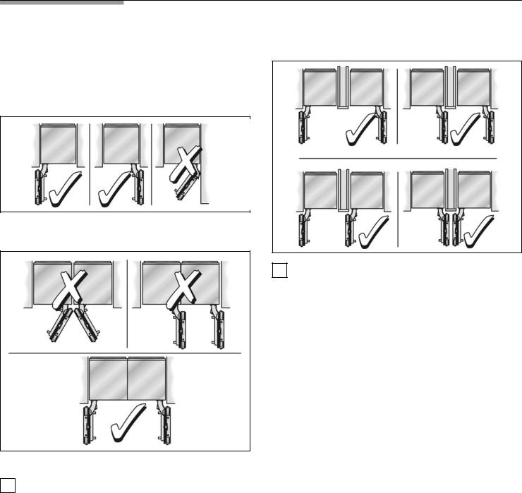
Installation options
There are many different installation options.
These are limited only by the design of the kitchen and the function of the finger guard.
Individual unit
Side0by0Side
*Partition required!
iWhen 2 appliances are installed Side by Side,
the Basic Combination Side0by0Side Sealing kit must be used to ensure a stable connection.
See the section on •Optional accessories" on page 17.
Individual appliances with partition
iNote
-When dimensioning the partition for model 4, note the thickness of the furniture fronts to prevent damage if the doors are opened at the same time.
-Use the Extreme Combination Side0by0Side Heating kit if the gap between the appliances is less than 6" (160 mm).
See the section on •Optional accessories" on page 17.
-Minimum thickness of the partition 5/8" (16 mm).
At the end of the kitchen units
If one side of the appliance is visible, a side panel must be used.
The side panel must be connected firmly to the wall, the floor and overhead furniture/fixtures before the appliance is placed in the cavity.
The dimensions of the side panel are taken from the opposite cavity wall. During installation ensure that the cavity is square and the exact size.
6

Installation location
d WARNING d
Do not install the appliance:
-outdoors,
-in an environment with dripping water,
-in rooms which are at risk of frost.
Appliance is very heavy = for empty weight see the following table:
Refrigerator 24" |
approx. 310 lbs / 140 kg |
Refrigerator 30" |
approx. 350 lbs / 158 kg |
Freezer 18" |
approx. 255 lbs / 115 kg* |
Freezer 24" |
approx. 300 lbs / 135 kg* |
Freezer 30" |
approx. 335 lbs / 150 kg* |
Wine unit 18" |
approx. 300 lbs / 135 kg |
Wine unit 24" |
approx. 360 lbs / 160 kg |
(* without Water Dispenser) |
|
Installation room
The appliance should be installed in a dry, ventilated room.
The ambient temperature should not drop below 55 °F (13 °C) or rise above 110 °F (43 °C), otherwise malfunctions may occur.
The installation location should not be exposed to direct sunlight and not placed near a heat source, such as an oven, radiator, etc. If installation next to a heat source is unavoidable, use a suitable insulating plate or observe the following minimum distances from the heat source:
-11/4" (30 mm) from an electric cooker,
-12" (300 mm) from an oil or solid fuel cooker.
Installation cavity
It is important to observe the specified dimensions of the installation cavity for a trouble free installation of the appliance and for the subsequent general view of the furniture front.
i In particular ensure that the cavity is square.
Squareness can be checked by suitable means, e.g. spirit level, diagonal measurements, etc.
i The side walls of the cavity must be flush.
The minimum thickness of side walls and the top wall must be 5/8" (16 mm).
The minimum thickness of toe kick panel must be 1/2" (13 mm).
A thickness of ¾" (19 mm) is recommended.
Furniture/fixtures
The new appliance is screwed securely to adjacent and overhead furniture/fixtures.
For this reason it is essential that all attachable furniture/fixtures are connected securely to the base or the wall by suitable means.
Base
d WARNING d
A fully load appliance is very heavy = for the load bearing capacity at least see the following table:
Refrigerator 24" |
approx. 890 lbs / 400 kg |
Refrigerator 30" |
approx. 1110 lbs / 500 kg |
Freezer 18" |
approx. 560 lbs / 250 kg* |
Freezer 24" |
approx. 780 lbs / 350 kg* |
Freezer 30" |
approx. 950 lbs / 425 kg* |
Wine unit 18" |
approx. 550 lbs / 245 kg |
Wine unit 24" |
approx. 694 lbs / 310 kg |
(* without Water Dispenser) |
|
To ensure that the appliance is installed securely and functions properly, the base must be flat and level.
The base must be made of a hard, rigid material.
The installation area must be the same height as the rest of the room.
On account of the heavy weight of a fully loaded appliance, a load bearing base is required. If in doubt, contact an architect or a building expert.
7

Connecting the power
d WARNING d
Electrical Shock Hazard
-Plug into a grounded 3 prong outlet.
-Do not remove ground prong.
-Do not use an adapter.
-Do not use an extension cord.
Failure to follow these instructions can result in death, fire, or electrical shock.
The appliance comes with a 3 wire power supply cord, UL listed in the USA.
The appliance requires a 3 wire receptacle.
The receptacle must be installed by a licensed electrician only.
The receptacle must be fitted with a 10A fuse or higher. Please observe in this coherence the following table:
Appliance |
Maximum load at one time |
|
|
Refrigerator24" |
2 Ampere |
Refrigerator 30" |
2 Ampere |
Freezer 18" (incl. IceMaker) |
3.5 Ampere |
Freezer 24" (incl. IceMaker) |
4 Ampere |
Freezer 30" (incl. IceMaker) |
4.5 Ampere |
Orient ground prong to the bottom as shown in the pictures.
For the installation position of the receptacle see "Installation dimensions", page 8.
Additional grounding procedure
Some local regulations may require a seperate ground. In such cases, the required accesseory ground wire, clamp and screw must be purchased seperately.
Never ground the appliance to plastic plumbing lines, gas lines or water pipes.
Grounding instruction
This appliance must be grounded. In the event of a malfunction or breakdown, grounding will reduce
the risk of electric shock by providing a path of least resistance for the electric current.
d WARNING d
Improper connection of the equipment grounding conductor may result in electric shock. Have the appliance checked by a qualified electrician or service technician if you are in doubt as to whether the appliance has been properly grounded.
Connecting the water
A cold water connection is required for operation of the automatic ice maker. The water pressure must be between 25 and 120 p.s.i. (1.72=8.25 bar).
The installation must comply with local plumbing regulations.
A separate shut off valve must be installed for the appliance water connection.
The shut off valve for the water connection must not be behind the appliance. It is recommended to place the shut off valve directly next to the appliance (base unit) or in another easily accessible location.
When installing the water connection, observe the permitted installation areas for the pipe. For the permitted installation areas and dimensions see •Installation dimensions", page 8.
The supply pipe can be located at the side on the right (a), at the side on the left (b) or underneath (c).
Maximum outer diameter of the water pipe (without fittings): 13/32" (10 mm).
Attach a separate shut off valve for the water connection in a suitable, easily accessible location. Do not use a self piercing valve!
8
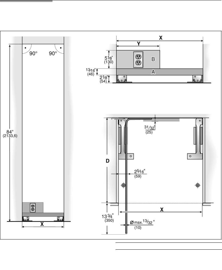
Installation dimensions
Single installation
Legend:
A Area for installation of the water connection B Area for installation of the power connection
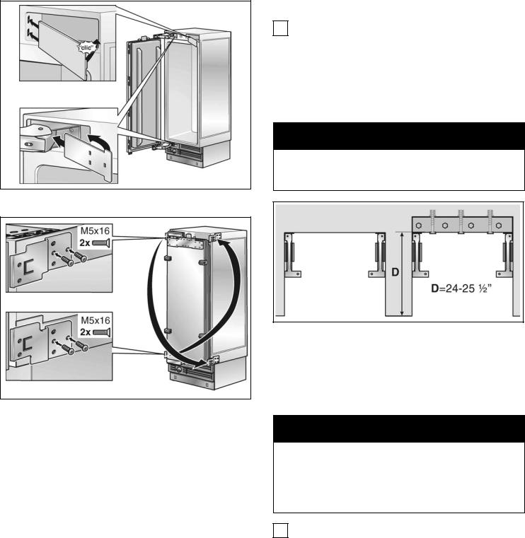
D Opening depth of niche, depending on kitchen design (see DESIGN GUIDE)
D = 24" (610 mm) minimum NOTE: Cavity must be suare.
Side wall of the cavity must be flush.
Appliance
|
18" |
24" |
30" |
X |
18" (457 mm) |
24• (610 mm) |
30" (762 mm) |
Y |
9" (229 mm) |
12" (305 mm) |
15" (381 mm) |
9
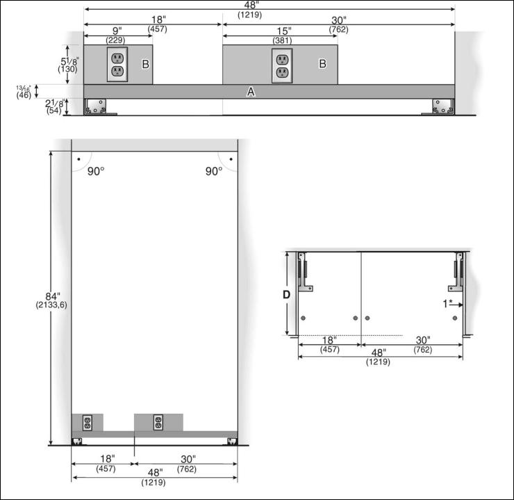
Side0by0Side installation
The cavity dimensions indicated above for the respective appliance apply to a Side by Side installation of two appliances.
The total width of the cavity results from the addition of the cavity widths indicated for the two appliances.
Example:
Freezer 18" / Refrigerator 30"
Legend:
A Area for installation of the water connection B Area for installation of the power connection
D Opening depth of niche, depending on kitchen design (see DESIGN GUIDE)
D = 24" (610 mm) minimum NOTE: Cavity must be suare.
Side wall of the cavity must be flush.
10
Water connection
The supply pipe can be located
a)at the side on the right,
b)at the side on the left or
c)underneath.
11
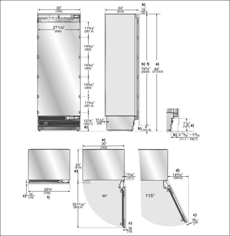
Appliance dimensions
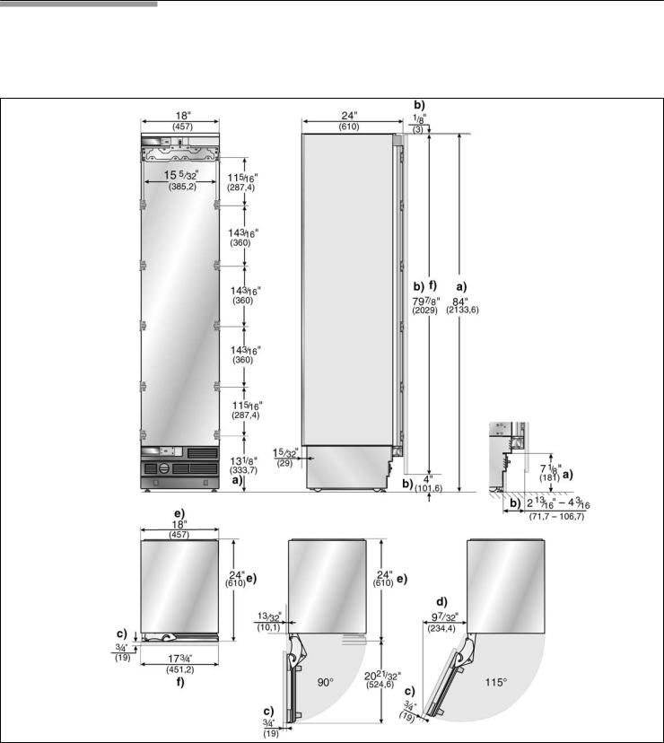
1. 18" Appliance (Freezer/Freezer with Ice and Water dispenser)
e) |
e) |
Front view
(without door panel)
Legend:
a)Adjustment in levelling legs +13/8" (35 mm) / -1/2" (13 mm).
b)Dimensions may vary.
c)Thickness of door panel may vary.
d)This dimension may vary depending on installation, panel thickness and kitchen hardware.
e) Unit dimensions
Note:
One design of the wooden panel displayed. For further information about the different styles check the DESIGN GUIDE.
12
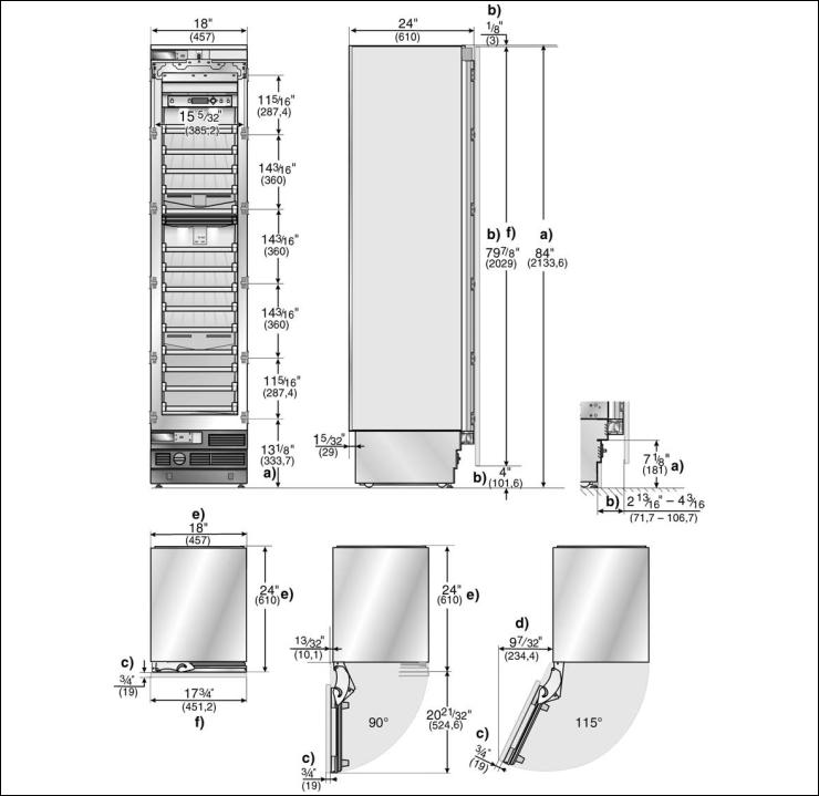
2. 18" Appliance (Wine unit)
e) |
e) |
Front view
(without door panel)
Legend:
a)Adjustment in levelling legs +13/8" (35 mm) / -1/2" (13 mm).
b)Dimensions may vary.
c)Thickness of door panel may vary.
d)This dimension may vary depending on installation, panel thickness and kitchen hardware.
e)Unit dimensions
Note:
One design of the wooden panel displayed. For further information about the different styles check the DESIGN GUIDE.
13
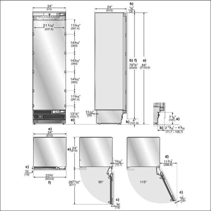
3.24" Appliance (Refrigerator/Freezer/Freezer with Ice and Water dispenser)
e) |
e) |
Front view
(without door panel)
Legend:
a)Adjustment in levelling legs +13/8" (35 mm) / -1/2" (13 mm).
b)Dimensions may vary.
c)Thickness of door panel may vary.
d)This dimension may vary depending on installation, panel thickness and kitchen hardware.
e)Unit dimensions
Note:
One design of the wooden panel displayed. For further information about the different styles check the DESIGN GUIDE.
14
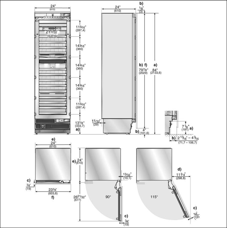
4. 24" Appliance (Wine unit)
e) |
e) |
Front view
(without door panel)
Legend:
a)Adjustment in levelling legs +13/8" (35 mm) / -1/2" (13 mm).
b)Dimensions may vary.
c)Thickness of door panel may vary.
d)This dimension may vary depending on installation, panel thickness and kitchen hardware.
e)Unit dimensions
Note:
One design of the wooden panel displayed. For further information about the different styles check the DESIGN GUIDE.
15
5.30" Appliance (Refrigerator/Freezer/Freezer with Ice and Water dispenser)
e) |
e) |
Front view
(without door panel)
Legend:
a)Adjustment in levelling legs +13/8" (35 mm) / -1/2" (13 mm).
b)Dimensions may vary.
c)Thickness of door panel may vary.
d)This dimension may vary depending on installation, panel thickness and kitchen hardware.
e)Unit dimensions
Note:
One design of the wooden panel displayed. For further information about the different styles check the DESIGN GUIDE.
16

Required accessories and tools
1. Supplied accessories
-Installation instructions
-Operating instructions
-Installation kit
2. Optional accessories
Basic Combination Side0by0Side Sealing kit
For permanent connection of two individual appliances, e. g. Freezer next to Refrigerator.
Extreme Combination Side0by0Side Heating kit
If the gap between the appliances is less than 6" (160 mm).
Extra long finger protection part
Panel unification part (Metal strip)
For connection of two furniture doors. Can be used for standard height furniture doors without further preliminary work.
3.Other required accessories from specialist outlets
Ice maker installation kit ¼" OD copper line
For connecting appliances which require water, e.g. for an ice maker.
i Maximum outer diameter of the water pipe (without fittings): 13/32" (10 mm).
-Cutter with adjustable blade
-Metal tape measure
-Square
-Spirit level length 2' (60 cm) and 4' (1,2 m)
-Marking out level, length at least 4' (1.2 m) for individual appliances or 7' (2.0 m) for Side by Side installation
5. Other
-Stepladder
-Dolly, hand truck
-Hammer drill for drilling holes in wall or floor
-Bits according suitable for material and in different sizes
-Wooden beam (cross section min. 3" x 4") as an alternative tilt protection, length according to the width of the installation cavity
-Wooden screws in different sizes
-Thin (max. 1/16" (1.5 mm)), suitable material to protect the floor from damage (e.g. lino)
-Suitable material for covering and protecting furniture (e.g. protective sheets)
-Adhesive tape
4. Tools
-Cordless screwdriver T20
-Torx screwdriver T20
-Torx bit T20 + magnetic holder
-5/16" (8 mm) hex nut driver
-Wood drills in different sizes
-Open end wrench ½" (SW 13 mm)
-Multigrip pliers
-Adjustable wrench
17
Installation instructions
d CAUTION d
The following installation instructions describe the installation steps for various appliance types:
-Refrigerator units
-Freezer units
-Freezer units with ice maker
-Freezer units with ice water dispenser
-Wine storage units
Therefore the diagrams may not be a true representation of your appliance.
Particular reference is made to special installation steps for individual appliance types.
1. Checking the installation cavity
d CAUTION d
To ensure a safe, trouble free installation and an optimum overall view of the subsequent furniture front, thoroughly check that the installation cavity complies with the installation requirements.
Before starting the installation, check that the installation cavity complies with all requirements for a safe and trouble free installation.
qCheck the base.
Follow the instructions in the section on •Installation location" on page 7.
qCheck the dimensions of the cavity.
qCheck that the cavity is square.
qCheck location of the socket.
Also follow the instructions in the section on •Connecting the power" on page 8 and in the section on •Installation dimensions" on page 9.
qCheck location of the water connection. (only for appliances with ice maker)
Also follow the instructions in the section on •Connecting the water" on page 8.
qCheck attachment of the adjacent furniture/fixtures. All furniture parts in the vicinity of the appliance must be connected securely to the wall.
qCheck that adjacent furniture/fixtures do not collide (door opening angle).
2.. Transport of the appliance
d CAUTION d
The appliance is very heavy. Be careful, otherwise people who are helping may be injured or the appliance may be damaged.
qTransport the appliance to a suitable installation location with suitable means of transportation (trolley, lifting truck or hand driven truck).
qSecure the appliance during transportation to prevent it from overturning.
The appliance is 2134 mm tall. If the appliance cannot be transported in an upright position due to the structural conditions, the appliance can be transported horizontally.
When erecting the appliance, observe the required minimum height at the installation location according to the following table:
Appliance width |
Erection via |
Erection via |
|
appliance rear |
appliance side panel |
|
|
|
18" / 457 mm |
86" / 2185 mm |
853/4" / 2180 mm |
24" / 610 mm |
86" / 2185 mm |
871/4" / 2215 mm |
30" / 762 mm |
86" / 2185 mm |
89" / 2260 mm |
|
|
|
36" / 914 mm |
86" / 2185 mm |
911/4" / 2315 mm |
18
3. Removing the packaging
d WARNING d
-The appliance may tip over while it is being unpacked.
-The appliance is very heavy.
-When opening the appliance door, the appliance may tip forwards.
Be careful, otherwise people who are helping may be injured or the appliance may be damaged.
To protect the base from damage during installation:
qAttach a residual piece of carpet, lino, etc. to the floor with adhesive tape in front of the intended installation location.
qMove the appliance with a hand truck securely.
qRemove transportation packaging:
-Remove the cartoon. Use the cutter securely to protect the surface of appliance.
-Take supplied accessories out of protection parts of packaging.
d CAUTION d
Do not remove transportation safety devices which protect the shelves and storage compartments inside the appliance until the installation is complete, otherwise the parts may be damaged.
qCheck appliance for damage in transit.
Do not install the appliance if it is visibly damaged. If in doubt, contact your dealer.
4. Preparing the appliance
qRemove the side brackets and fixing plates which attach the furniture fronts.
To do this, loosen the fastening screws and remove the stop parts.
iStore the stop parts in suitable receptacles, otherwise they may get lost.
19
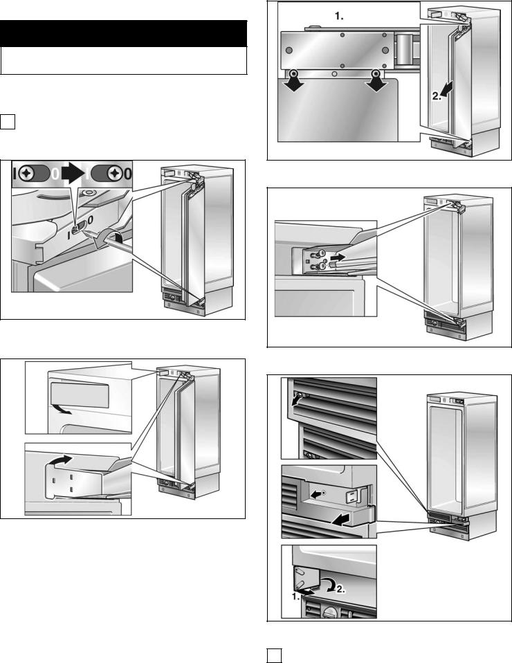
5. Changing over the door hinges
d CAUTION d
Before working on the hinge, release the spring = risk of injury!
The door hinges may have to be changed over depending on the installation situation.
iIf it is not necessary to change over the door hinges, continue with the next installation step.
q Unscrew the door.
qRelease the spring on the hinge. Loosen the screw from I to 0.
q Remove the hinges.
qRemove the hinge box covers.
q Remove the parts of grill. i It will used new parts.
20

qChange over the hinge angle.
qFit the plastic part of the grill.
qMount the grill completely.
qChange over the fixation parts on the door.
qFix the hinges on the appliance. Change the hinges crosswise!
qFix the door.
qSpan the spring on the hinge. Tighten the screw from 0 to I.
21
qFix the hinge box cover.
qChange the attachment plates crosswise.
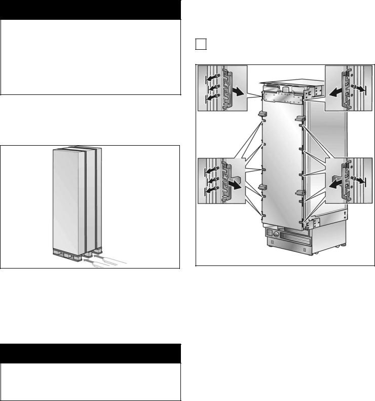
6. Preparing the installation cavity
i2 anti tip brackets are required for each appliance or appliance combination (Side by Side).
qSpecify the attachment points of the anti tip brackets.
Specify the detailed dimensions according to the section on •Installation dimensions" starting on page 9.
d WARNING d
Assure that there are no electrical wires or plumbing in the area which the screws could penetrate - risk of injury and damage!
(609,6-647,7)
qIf the installation cavity is deeper than the appliance, place a solid wooden beam behind the anti tip brackets and attach securely to the base or the wall.
The length of the wooden beam is equal to the width of the installation cavity!
! IMPORTANT NOTE !
If possible, always screw the wooden beam to existing studs on the rear panel of the cavity.
In some installations the sub flooring or finished floor may necessitate angling the wood screws used to fasten the anti tip brackets to the back wall.
iImportant information for secure attachment of the anti tip brackets:
-The supplied set contains fastening screws for various applications. Select the fastening screws according to the local conditions.
-If the supplied fastening screws do not permit secure attachment of the anti tip brackets and therefore the appliance, another method must be used to attach the anti tip brackets securely.
22
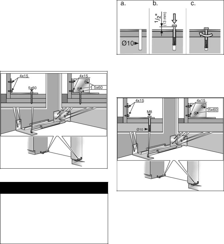
Wood floor application
Use the wooden screws provided, see overview diagram •Use the screws in the screws set".
qDrill pilot holes:
1/8" (3 mm) for the (5 x 60 mm) wooden screws
5/64" (2 mm) for the (4 x 15 mm) wooden screws
Being certain the screws penetrate through the flooring and into the wall plate a minimum of 3/4" (19 mm).
qAttach the anti tip bracket completely. Be sure screws hold tight.
Concrete floor applications
d CAUTION d
Always wear safety glasses and other necessary protective devices or apparel when installing or working with anchors = risk of injury!
Not recommended for use in light weight masonry material such as block or brick.
Not recommended for use in new concrete which has not had time to cure.
Do not use core drills to drill holes for this anchor.
Use concrete anchor M8 and M8 srew. Additional use the wooden screws provided, see overview diagram •Use the screws in the screws set".
qDrill a 10 mm diameter hole any depth exceeding the minimum embedment. Use the provided drill.
qClean hole or continue drilling additional depth.
qManually insert the screw into the wall plug until the screw begins to resist.
qKnock the wall plug and screw into the hole until the screw head is approx. ½" (13 mm) from the anti tip bracket.
qTighten the screw.
23
7.Attaching an alternative anti0tip device
! IMPORTANT NOTE !
If possible, always screw the wooden beam to existing studs on the rear panel of the cavity.
If the anti tip brackets cannot be attached securely, an alternative anti tip device can be attached. However, ensure that there is no play between the appliance and the anti tip device.
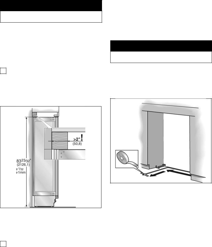
qSaw the wooden beam (cross section min. 3" x 4") to the required length.
Length is equal to the width of the installation cavity!
iNote
-If the installation cavity is deeper than the appliance, select a beam which has a larger cross section or attach 2 beams.
-The beam must cover the appliance by at least 2" (50.8 mm).
qMark the installation height (lower edge of the beam) on the rear panel of the cavity.
qSelect screws according to the thickness of the wooden beam: length = min. 2.5 x beam thickness, diameter #12 or #14.
iSpecify the number of screws according to the cavity width, thereby ensuring that the beam can be attached securely.
qLocate wall studs near the rear panel of the cavity and mark drill holes in the beam.
qPredrill the wooden beam.
qAttach the wooden beam to the rear panel of the cavity.
8. Preparing to connect the water
(only for appliances which require a water connection)
d CAUTION d
Turn off the main water tap to prevent damage caused by leaking water.
qAttach the connecting pipe to the shut off valve according to the instructions supplied by the manufacturer of the ice maker installation kit.
qInstall the connecting pipe. Always observe the indicated gap dimensions to prevent damage to the connecting pipe when pushing in the appliance.
qAttach the connecting pipe to the floor with adhesive tape.
24
9. Attaching the edge protection |
10.Side0by0Side installation |
|
i If a side by side installation is intended, |
|
|
|
now connect the two appliances together. |
|
See the Installation Manual for the Side by Side kits. |
|
|
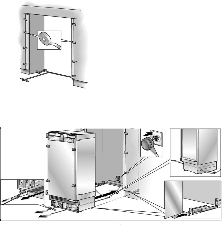
qTo protect the corners of the installation cavity, attach the supplied protective brackets with adhesive tape.
11. Pushing the appliance into the installation cavity
d |
CAUTION |
d |
i When the floor or the appliance is tilted in |
|
|
|
|
comparison to the installation cavity adjust height |
|
Caution when pushing the appliance into the |
|
adjustable wheels before you move the appliance |
||
installation cavity. Do not damage the water pipe |
|
into the installation cavity. |
||
or power cord attached to the floor. |
|
|
||
|
|
|
|
|
25
qPut the mains plug into the socket.
iIn the case of Side by Side appliances a separate socket must be used for each appliance.
qPrevent the power cord from becoming caught.
Tie a piece of string to the middle of the power cord and feed forwards under the appliance. When pushing in the appliance, pull the cable forwards.
or
Using adhesive tape, stick the power cord to the floor centrally behind the appliance approx. 15" (380 mm) away from the rear panel of the cavity.
qCarefully push the appliance into the cavity until the height adjustable wheel interlock with the anti tip brackets.
qRemove edge protection.
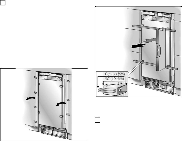
12.Installing and aligning the appliance
qAlign the appliance with the furniture fronts.
Place marking out level over the installation aid parts on the door.
iThe installation aid parts on the door have been designed for the following total thickness of furniture doors:
-¾" (19 mm)
-1½" (38 mm)
Always take account of the possible differing thickness of the furniture fronts which are to be fitted subsequently.
26
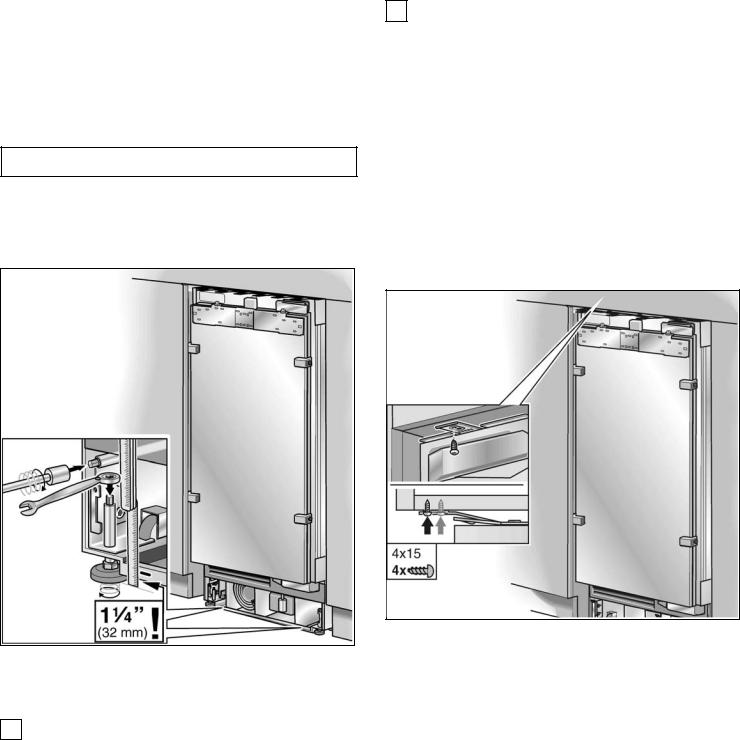
The height adjustable feet at the front and rear can all be adjusted from the front.
Front: |
with open ended wrench 1/2" (SW13) |
||
Rear: |
with 5/16" (8 mm) hex nut driver |
|
|
|
via flexible shaft. |
|
|
|
|
|
|
d |
CAUTION |
d |
|
|
|
|
|
Never use a cordless screwdriver!
A mark is attached to the appliance base and is used as a standard gage for height adjustment. When adjusting the height, align this mark at a height of 1¼" (32 mm) above the floor.
qUnscrew the height adjustable feet until the mark on the base has reached the indicated guide dimension (1¼" / 32 mm).
iIt is very important to comply with this dimension for the subsequent alignment of the furniture fronts.
qAlign the furniture fronts with the spirit level.
iNote:
-Do not twist or jam the appliance inside the cavity! When unscrewing the height adjustable feet, proceed gradually: Always alternate between left and right, left and right, etc..
-The adjustment of the rear feet is facilitated if the appliance is unloaded at the rear.
-If using a wooden beam as an alternative anti tip device according to point 6 of this installation manual, rotate the appliance all the way towards the wooden beam.
13.Attaching the appliance to the top of the cavity
qScrew the attachment plate lugs (top) to the overhead furniture/fixtures.
27
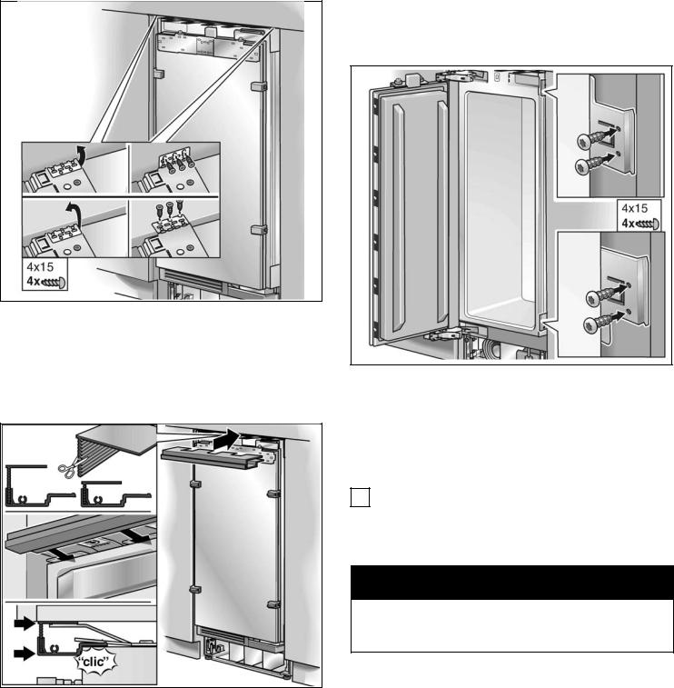
14.Attaching the individual appliance to the side of the cavity
qFix the attachment plate side lugs (top) depending on the installation situation. If there is no gap or only a slight gap, it is not necessary to fix the side lugs.
qIf there is a fairly large gap above the appliance, fit a wooden beam above the appliance, ensuring that the wooden beam fits the gap exactly.
qScrew the attachment plate lugs (side) to the adjacent furniture/fixtures (individual appliances only).
qAttach the cover strip to the attachment plate (top). Shorten the fitting strip to the required height!
15.Connecting the water to the appliance
iWhen connecting the water pipe to the solenoid valve of the appliance, follow the instructions supplied by the manufacturer of the ice maker installation kit enclosed with the installation manual.
d CAUTION d
When bending the water pipe, do not kink it, otherwise there is a risk of leaks and water damage. Use bending aids.
28
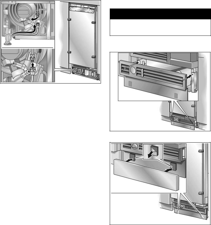
1.
2.
3.
qRemove the cap from the appliance connection 1.
qBend the water pipe according to the location of the connection on the appliance 2.
qPush the union nut and seal onto the water pipe.
qPush the end of the water pipe into the appliance connection and screw on the union nut 3. Tighten hand tight.
qUsing the open ended wrench, tighten the union nut. Do not overturn!
qOpen the shut off valve and main water tap. Check the connection on the shut off valve and on the appliance for leaks.
16. Attaching the toe kick panel
d CAUTION d
The maximum height of the toe kick panel is 4" from the top of the floor. Do not cover ventilation slots in the base panel. Risk of damage to the appliance.
qIf required, cut the toe kick panel to the required length.
qAttach the base panel to the appliance.
qRemove the protective film from the adhesive pads on the Velcro.
qFit the toe kick panel to the base panel and press firmly into place.
29

qPut on the base panel (do not screw on) and measure the difference in depth Y between the base panel and toe kick panel of the adjacent furniture.
qRemove the base panel.
qLoosen the brackets for attaching the base panel and push in all the way.
qAttach the base panel.
iIf required, the toe kick panel can be screwed to the base panel. There are screw holes in the base panel near the Velcro.
qPull out the brackets by the measured amount Y.
qScrew the brackets tightly.
17. Commissioning the Appliance
To guarantee the accuracy of the following working steps and thus the appearance of the overall kitchen front later on, the appliance should now be operated.
qOpen the appliance door.
qPress the POWER button.
Only for appliances with a water connection:
! |
NOTE |
! |
|
|
|
|
In order to avoid the risk of damage caused by leaking water from damage possibly caused to the water pipe feeding the appliance, keep the shut off valve closed.
30
 Loading...