


 Loading...
Thermador MEM301WS, PODMC301W, POD302W, MED301WS, MEDS301WS Installation Manual
...
Installation
G U I D E
Masterpiece® and Professional Series Built-In Oven
ME301WS MED301WS MED301LWS MED301RWS PO301W POD301W POD301LW POD301RW ME302WS MED302WS MED302LWS MED302RWS PO302W POD302W POD302LW POD302RW MEM301WS POM301W MEDMC301WS PODMC301W MEDMCW31WS PODMCW31W MEDS301WS PODS301W MEDS302WS PODS302W
T H E R M A D O R . C O M

Table of
C O N T E N T S
Safety Definitions ....................................................... |
3 |
IMPORTANT SAFETY INSTRUCTIONS ........................ |
4 |
Appliance Handling Safety ............................................. |
4 |
Safety Codes and Standards ........................................... |
4 |
Electric Safety ................................................................. |
4 |
Related Equipment Safety .............................................. |
4 |
State of California Proposition 65 Warning: ................... |
4 |
Transport ......................................................................... |
5 |
Preparation ................................................................. |
6 |
Model Numbers Covered in this Manual ........................ |
6 |
Before you Begin ............................................................ |
6 |
Checklist for Installation ............................................. |
7 |
Removing Packaging .................................................. |
7 |
Left Packaging Bracket Removal .................................... |
7 |
Right Packaging Bracket Removal .................................. |
7 |
Electrical Installation .................................................. |
8 |
Electrical Connection ...................................................... |
8 |
Four-wire Connection (Preferred) ................................... |
8 |
Three-wire Connection ................................................... |
8 |
Four-wire Connection for Steam Oven ........................... |
9 |
Three-wire Connection for Steam Oven ......................... |
9 |
Oven Installation ........................................................ |
9 |
For Best Installation ........................................................ |
9 |
Removing the Oven Door ............................................... |
9 |
Placing the Oven into the Cabinet Opening ................ |
12 |
Reinstalling Oven Doors with Bottom Hinge ................ |
13 |
Aligning Side Hinge Oven Doors .................................. |
13 |
Side Hinge Door Alignment Procedure ........................ |
14 |
Side Hinge Door Troubleshooting Guide ..................... |
15 |
Testing Operation ..................................................... |
16 |
Service ...................................................................... |
16 |
Before Calling Service ................................................... |
16 |
Single Oven-Side Hinge ................................................ |
16 |
Single Oven-Bottom Hinge ........................................... |
16 |
Double Oven-Side Hinge .............................................. |
17 |
Double Oven-Bottom Hinge ......................................... |
17 |
Cabinet Requirements .............................................. |
18 |
Door Handle Depth ...................................................... |
18 |
Appliance and Cabinet Cutout Dimensions ............. |
19 |
Dimensions for Single Oven Units ................................ |
19 |
Dimensions for Steam and Convection Oven Units ...... |
21 |
Dimensions for Steam and Convection Oven with Storage |
|
Drawer ........................................................................... |
22 |
Dimensions for Double Oven Units .............................. |
23 |
Dimensions for Combination Oven with Steam and |
|
Convection Oven Units ................................................. |
25 |
Dimensions for Combination Oven with Microwave or |
|
Speed Oven .................................................................. |
26 |
Dimensions for Triple Oven with Speed Oven and |
|
Warming Drawer ........................................................... |
27 |
THERMADOR® Support .......................................... |
28 |
Service ........................................................................... |
28 |
Parts and Accessories ................................................... |
28 |
Safety Definitions
9WARNING
This indicates that death or serious injuries may occur as a result of non-observance of this warning.
9CAUTION
This indicates that minor or moderate injuries may occur as a result of non-observance of this warning.
NOTICE: This indicates that damage to the appliance or property may occur as a result of non-compliance with this advisory.
Note: This alerts you to important information and/or tips.
3

9 IMPORTANT SAFETY INSTRUCTIONS
READ AND SAVE THESE INSTRUCTIONS
IMPORTANT: SAVE THESE INSTRUCTIONS FOR THE LOCAL ELECTRICAL INSPECTOR’S USE.
INSTALLER: LEAVE THESE INSTALLATION INSTRUCTIONS WITH THE UNIT FOR THE OWNER.
OWNER: PLEASE RETAIN THESE INSTRUCTIONS FOR FUTURE REFERENCE.
WARNING
If the information in this manual is not followed exactly, fire or shock may result causing property damage or personal injury.
WARNING
Do not repair, replace or remove any part of the appliance unless specifically recommended in the manuals. Improper installation, service or maintenance can cause injury or property damage. Refer to this manual for guidance. All other servicing should be done by an authorized servicer.
Appliance Handling Safety
CAUTION
Unit is heavy and requires at least two people or proper equipment to move.
For double and triple ovens three or more people are needed to assist with lifting the unit in to place.
Do not lift appliance by door handle.
Hidden surfaces may have sharp edges. Use caution when reaching behind or under appliance.
Safety Codes and Standards
This appliance complies with the latest version of one or more of the following standards:
CAN/CSA C22.2 No. 61 - Household Cooking Ranges
UL 858 - Household Electric Ranges
CAN/CSA C22.2 No. 150 - Microwave Ovens
UL 923 - Microwave Cooking Appliances
CSA C22.2 No. 64 - Household Cooking and LiquidHeating Appliances
UL 1026 - Electric Household Cooking and Food Serving Appliances
It is the responsibility of the owner and the installer to determine if additional requirements and/or standards apply to specific installations.
Electric Safety
Before you plug in an electrical cord, be sure all controls are in the OFF position.
If required by the National Electrical Code (or Canadian Electrical Code), this appliance must be installed on a separate branch circuit.
Installer - show the owner the location of the circuit breaker or fuse. Mark it for easy reference.
Important - save these instructions for the local electrical inspector’s use.
Before installing, turn power OFF at the service panel. Lock service panel to prevent power from being turned ON accidentally.
Refer to rating label for more information. See “Rating Label” under “Service” for rating label location.
Be sure your appliance is properly installed and grounded by a qualified technician. Installation, electrical connections and grounding must comply with all applicable codes.
Related Equipment Safety
Remove all tape and packaging before using the appliance. Destroy the packaging after unpacking the appliance. Never allow children to play with packaging material
Never modify or alter the construction of the appliance. For example, do not remove leveling legs, panels, wire covers or anti-tip brackets/screws.
Before starting up the appliance, remove any packaging material and adhesive film from the cooking compartment and the door.
State of California Proposition 65 Warning:
WARNING
This product can expose you to chemicals including vinyl chloride, which is known to the State of California to cause cancer and birth defects or other reproductive harm. For more information go to
www.P65Warnings.ca.gov.
4
9 IMPORTANT SAFETY INSTRUCTIONS
READ AND SAVE THESE INSTRUCTIONS
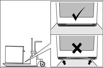
Transport
To avoid damage to the oven vent, use the transport method shown in the picture below.
5
Preparation
Model Numbers Covered in this Manual
Model |
Type |
Series |
ME301WS |
Single Oven |
Masterpiece |
|
|
|
MED301WS |
Single Oven |
Masterpiece |
MED301LWS |
Single Oven |
Masterpiece |
|
|
|
MED301RWS |
Single Oven |
Masterpiece |
|
|
|
PO301W |
Single Oven |
Professional |
POD301W |
Single Oven |
Professional |
|
|
|
POD301LW |
Single Oven |
Professional |
|
|
|
POD301RW |
Single Oven |
Professional |
ME302WS |
Double Oven |
Masterpiece |
|
|
|
MED302WS |
Double Oven |
Masterpiece |
|
|
|
MED302LWS |
Double Oven |
Masterpiece |
MED302RWS |
Double Oven |
Masterpiece |
|
|
|
PO302W |
Double Oven |
Professional |
|
|
|
POD302W |
Double Oven |
Professional |
POD302LW |
Double Oven |
Professional |
|
|
|
POD302RW |
Double Oven |
Professional |
|
|
|
MEM301WS |
Combination Oven |
Masterpiece |
with Microwave |
|
|
|
|
|
|
|
|
POM301W |
Combination Oven |
Professional |
with Microwave |
|
|
|
|
|
MEDMC301WS |
Combination Oven |
Masterpiece |
with Speed Oven |
|
|
|
|
|
|
|
|
PODMC301W |
Combination Oven |
Professional |
with Speed Oven |
|
|
|
|
|
|
|
|
|
Triple Oven with Speed |
Masterpiece |
MEDMCW31WS |
Oven and Warming |
|
|
Drawer |
|
|
|
|
|
Triple Oven with Speed |
Professional |
PODMCW31W |
Oven and Warming |
|
|
Drawer |
|
|
|
|
MEDS301WS |
Steam and Convec- |
Masterpiece |
tion Oven |
|
|
|
|
|
|
|
|
PODS301W |
Steam and Convec- |
Professional |
tion Oven |
|
|
|
|
|
|
|
|
|
Combination Oven |
Masterpiece |
MEDS302WS |
with Steam and Con- |
|
|
vection Oven |
|
|
|
|
|
Combination Oven |
Professional |
PODS302W |
with Steam and Con- |
|
|
vection Oven |
|
|
|
|
Before you Begin
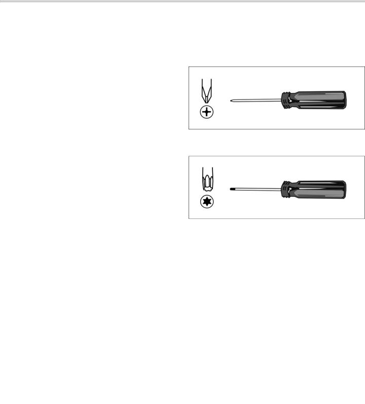
Tools and Parts Needed
#2 Phillips head screwdriver (to install trim screws).
T20 Star-head screwdriver (to remove shipping screws).
1/8” drill bit and drill (to drill pilot holes for trim screws).
Measuring tape.
Gloves and long sleeves are recommended (to help protect hands and arms from scratches).
Parts Included
Phillips head screws (6).
Power Requirements
The junction box must be properly grounded in accordance with all applicable codes.
6
Checklist for Installation
Use this checklist to verify that you have completed each step of the installation process. This can help you avoid common mistakes.
Always read and follow the complete installation instructions contained in this manual.
Refer to detailed instructions for each step in the sections following this checklist.
1.Before installing the oven, be sure to verify the cabinet dimensions are correct for your unit and that the required electrical connections are present. Make sure the electrical conduit provided on the unit is able to reach to the point of connection.
Section: Dimensions and Cabinet Requirements
2.Move the oven unit into place in front of the cabinet opening.
Section: Removing Packaging
3.Remove packaging materials, leaving the bottom packaging on the unit to avoid damaging flooring.
Section: Removing Packaging
4.Remove the T20 (star head) screws holding the unit to the base of the carton.
Section: Removing Packaging
5.Perform Electrical Installation.
Section: Electrical Installation
6.Remove the oven door or doors (bottom hinge only).
Section: Oven Installation, "Removing the Oven Door"
7.Team lift the unit directly into the cabinet cutout.
Section: Oven Installation, "Placing the Oven into the Cabinet Opening"
8.Slide the unit all the way into place.
Section: Oven Installation, "Placing the Oven into the Cabinet Opening"
9.Fasten the oven unit to the cabinetry opening with the screws supplied.
Section: Oven Installation, "Placing the Oven into the Cabinet Opening"
10.Reinstall the oven door(s).
Section: Oven Installation, "Placing the Oven into the Cabinet Opening"
Removing Packaging
NOTICE: To prevent damage to your floor keep the unit in its packaging base until ready to be placed in the cabinet opening. Do not slide the unit across the flooring.
Different models use different packaging materials. Actual brackets may look differently. Bracket remains in packaging base.
1.Cut straps on outside of box.
2.Remove cardboard box.
3.Remove all top and side cardboard, foam and wood packaging.
4.Place oven (leaving it on the shipping base) in front of the cabinet where it is to be installed.
5.Remove all accessories, racks, packing materials and literature from the oven cavity. Check both cavities for double ovens.
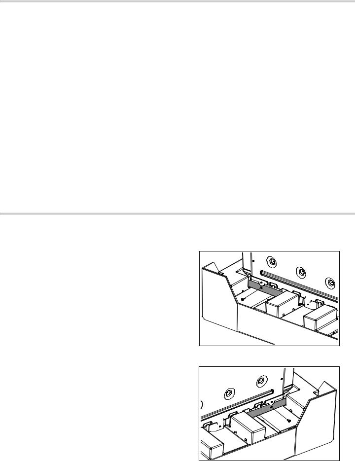
6.Unscrew unit from packaging brackets as shown. The screws near the base mounting bracket are all T20 size. Only the one screw that goes through the slotted hole in the mounting bracket on the left and right sides of the unit needs to be removed in order to lift the unit from the mounting base.
Left Packaging Bracket Removal
Right Packaging Bracket Removal
7
Electrical Installation
All model ovens on the front cover are dual rated, designed to be connected to either 208/240V AC, 60 Hz, 4 wire, single-phase power supply.
|
Circuit |
Watts |
Circuit |
Watts |
|
Model |
@ |
@ |
|||
Required |
Required |
||||
|
240v |
208v |
|||
|
|
|
|
|
|
MEDS301WS |
20 AMP |
4100 |
20 AMP |
3500 |
|
PODS301W |
|||||
|
|
|
|
||
|
|
|
|
|
|
ME301WS |
|
|
|
|
|
MED301LWS |
|
|
|
|
|
MED301RWS |
|
|
|
|
|
MED301WS |
30 AMP |
6400 |
30 AMP |
4800 |
|
POD301W |
|||||
|
|
|
|
||
POD301LW |
|
|
|
|
|
POD301RW |
|
|
|
|
|
POD301W |
|
|
|
|
|
|
|
|
|
|
|
ME302WS |
|
|
|
|
|
PO302W |
40 AMP |
9200 |
40 AMP |
7000 |
|
MEDS302WS |
|||||
|
|
|
|
||
PODS302W |
|
|
|
|
|
|
|
|
|
|
|
MED302WS |
|
|
|
|
|
MED302LWS |
|
|
|
|
|
MED302RWS |
40 AMP |
9600 |
40 AMP |
7500 |
|
POD302W |
|||||
|
|
|
|
||
POD302LW |
|
|
|
|
|
POD302RW |
|
|
|
|
|
|
|
|
|
|
|
MEDMC301WS |
|
|
|
|
|
MEDMCW31WS- |
|
|
|
|
|
MEM301WS |
50 AMP |
10200 |
40 AMP |
8300 |
|
PODMC301W |
|||||
|
|
|
|
||
PODMCW31W |
|
|
|
|
|
POM301W |
|
|
|
|
|
|
|
|
|
|
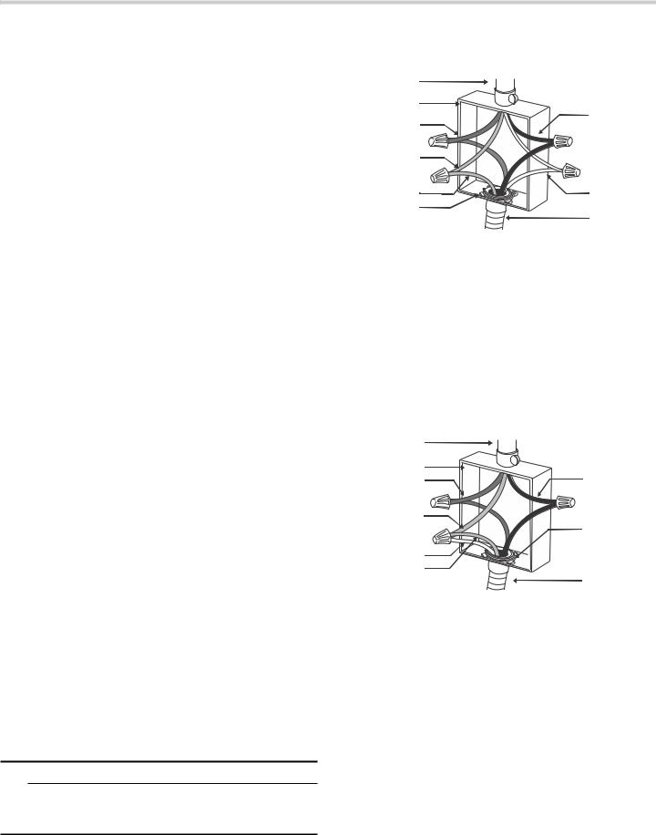
The electrical supply should be a 4-wire single-phase AC. Install a suitable conduit box (not furnished). An appropriately-sized, UL-listed conduit connector must be used to correctly attach the conduit to the junction box.
Note: Local Codes may vary; installation, electrical connections and grounding must comply with all applicable local codes.
If local codes permit grounding through the electrical supply neutral, connect both the white neutral wire and the bare ground wire from the oven to the white neutral electrical supply wire.
Electrical Connection
The four-wire connection is preferred, but where local codes permit, the three wire connection is also acceptable.
9WARNING
When connected to a 4 or 5-wire, 120/208-Volt 3- phase power supply, the phase C conductor is not required for the operation of the appliance.
Four-wire Connection (Preferred)
SRZHU VXSSO\
MXQFWLRQ ER[
EODFN ZLUHV
UHG ZLUHV
JUHHQ RU EDUH
ZLUH |
|
JUHHQ ZLUH |
ZKLWH ZLUHV |
8/ OLVWHG |
|
FRQQHFWRU |
FDEOH IURP |
|
RYHQ |
Connect the red oven wire to the red electrical supply wire (hot wire).
Connect the black oven wire to the black electrical supply wire (hot wire).
Connect the white neutral oven wire to the white neutral (not bare or green ground) electrical supply wire.
Connect the green ground oven wire to the bare or green ground electrical supply wire.
Three-wire Connection
Grounded Neutral
SRZHU VXSSO\ |
|
|
MXQFWLRQ ER[ |
EODFN ZLUHV |
|
UHG ZLUHV |
||
|
||
ZKLWH EDUH RU |
8/ OLVWHG |
|
JUHHQ ZLUH |
||
FRQQHFWRU |
||
|
||
ZKLWH ZLUH |
|
|
JUHHQ ZLUH |
FDEOH IURP |
|
|
RYHQ |
Connect red wire from oven to red wire in junction box.
Connect black wire from oven to black wire in junction box.
Connect both green ground wire and white wire from oven to white, green or bare neutral wire in junction box.
The conduit cable, where connected at the oven, swivels. Rotate conduit cable upward (or downward) and direct through hole prepared in cabinet to attach to junction box.
To maintain serviceability, the flex conduit must not be shortened and should be routed to permit temporary removal of the oven.
8
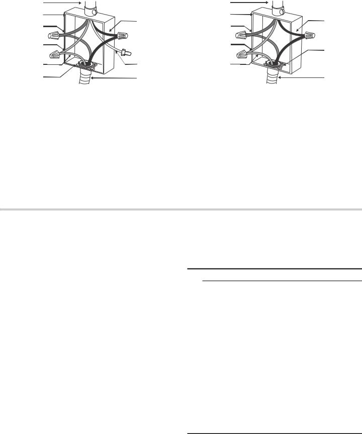
Four-wire Connection for Steam Oven |
Three-wire Connection for Steam Oven |
SRZHU VXSSO\ |
|
|
MXQFWLRQ ER[ |
EODFN ZLUHV |
|
UHG ZLUHV |
||
|
||
JUHHQ RU EDUH |
|
|
ZLUH |
|
|
JUHHQ ZLUH |
ZKLWH ZLUH |
|
8/ OLVWHG |
FDEOH IURP |
|
FRQQHFWRU |
RYHQ |
Connect the red oven wire to the red electrical supply wire (hot wire).
Connect the black oven wire to the black electrical supply wire (hot wire).
Connect the green ground oven wire to the bare or green ground electrical supply wire.
A neutral wire connection (white wire) is not required for operation of the oven.
SRZHU VXSSO\ |
|
|
MXQFWLRQ ER[ |
EODFN ZLUHV |
|
UHG ZLUHV |
||
|
||
ZKLWH EDUH RU |
|
|
JUHHQ ZLUH |
8/ OLVWHG |
|
JUHHQ ZLUH |
FRQQHFWRU |
|
|
||
|
FDEOH IURP |
|
|
RYHQ |
Connect red wire from oven to red wire in junction box.
Connect black wire from oven to black wire in junction box.
Connect green ground wire from oven to white, green or bare neutral wire in junction box.
The conduit cable, where connected at the oven, swivels. Rotate conduit cable upward (or downward) and direct through hole prepared in cabinet to attach to junction box.
To maintain serviceability, the flex conduit must not be shortened and should be routed to permit temporary removal of the oven.
Oven Installation
NOTICE: Before installing the appliance, be sure to verify the cabinet dimensions and electrical connections.
For Best Installation
The oven can be difficult for two people to handle during installation. It is recommended to have three or more people available to assist with lifting the unit into place.
Removal of the oven door during installation (to provide the necessary handholds and to significantly reduce the unit weight) can be cumbersome unless the detailed door removal instructions are followed carefully. Please take time to read and follow the instructions provided for an improved installation experience.
Removing the Oven Door
Note: Only bottom hinge doors can be removed. Do not remove side hinge or steam convection oven doors.
9CAUTION
WHEN REMOVING THE OVEN DOOR:
The oven door is heavy and fragile. Use both hands to remove the oven door. The door front includes glass components. Handle carefully to avoid breaking.
Grasp only the sides of the oven door. Do not grasp the handle as it may swing in your hand and cause damage or injury.
Failure to grasp the oven door firmly and properly could result in personal injury or product damage.
To avoid injury from hinge bracket snapping closed, be sure that both locking levers are securely in place before removing the door. Also, do not force the oven door open or closed - the hinge could be damaged and injury could result.
Do not lay the removed door on sharp or pointed objects as this could break the glass. Lay the door on a flat, smooth surface, positioned so that the door cannot fall over.
9
Remove Lower Oven Door Prior to Installation
Note: Do not remove microwave, speed oven, side hinge or steam convection oven doors.
It is recommended to remove the traditional (lower) oven door to help reduce the unit weight and provide easier access to the latch levers located inside the oven.
Note: Be sure to read all warnings and cautions in the installation manual regarding the door removal before attempting to remove the door.
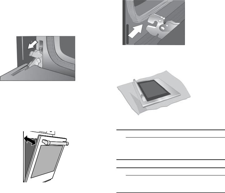
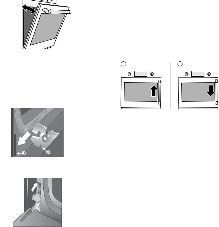
1.Open the door completely to its fully open, horizontal position.
2.Flip latch levers on hinges all the way down toward you.
Note: It may be necessary to use a tool, such as a screwdriver, to gently pry the upper part of the lever away from the housing. Take care to avoid scratching the housing.
3.Close the oven door until it catches on the hinge stop levers, locking the hinges at the proper angle for door removal. The door will be open about 7 inches at the top. This takes the spring tension off the hinges so the door can be easily lifted out.
4.Carefully lift the door up and out of the hinge slots. Hold firmly; the door is heavy. Use both hands to firmly grip it by the sides. Do not grip the door by the handle. Maintaining the door angle, lift the door straight up approximately 3/4” to unhook the hinges from the slots and then pull it out towards you until the hinges are clear of the oven housing.
5.Place the door in a convenient and stable location until you are ready to reinstall it. Lay the door on a towel or section of protective foam padding to avoid damage to the door or the floor.
Correctly Lifting the Combination Oven
9CAUTION
Wear gloves and a long-sleeved shirt to protect hands and forearms from abrasion, potential scratches or cuts. Take off watches and jewelry and wear work shoes for foot protection.
9CAUTION
Three people or proper equipment are needed to safely lift the combination oven into the cabinet opening.
NOTICE: DO NOT attempt to lift the unit by holding the oven’s upper element.
10
Lifting Recommendations
There is a ridge across the top front of the oven cavity. Lift by grasping this ridge with one hand while placing the other hand on the back of the unit (for helpers lifting from the sides of the unit). If a third helper is lifting from the front, both hands should lift by holding this ridge area.
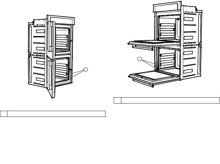
Lifting Locations-Bottom Hinge Door
Note: It is recommended to remove the door to help reduce the unit weight and provide easier access to the handholds located inside the oven.
Proceed to lift the oven following the guidelines below with the door removed
Lift points (1) on the front of the unit are for lifting from the sides of the unit. Lift point (3) on the front of the unit is for a third person to help lift the unit.
Lift point (2) on the back of the unit shows the location of the opposite hand for the helpers lifting from the sides of the unit. Adjust the location as needed to facilitate the lift.
Single Oven-Bottom Hinge Double Oven-Bottom Hinge


|
|
|
|
|
Proceed to lift the oven following the guidelines below with the door open to 90°-110°:
Lift points (1) on the front of the unit are for lifting from the sides of the unit. Lift point (3) on the front of the unit is for a third person to help lift the unit.
Lift point (2) on the back of the unit shows the location of the opposite hand for the helpers lifting from the sides of the unit. Adjust the location as needed to facilitate the lift.
Single Oven-Side Hinge |
Double Oven-Side Hinge |
||
|
|
|
|
|
|
|
|
|
|
|
|
|
|
|
|
|
|
||
|
|
|
|
Lifting Locations-Side Hinge Door
Note: Do not attempt to remove the side hinge door.
Lift locations are called out for door opened to 90°- 110°).
11

Placing the Oven into the Cabinet Opening
9CAUTION
To avoid potential damage to flooring keep the unit on its base packaging until immediately before placing the unit directly into the cabinet opening. Do not allow the metal base of the unit to contact the flooring. See the following handling instructions for details.
To avoid damage to the door (and/or warming drawer front for combo units) do not lift, pull or push the unit during installation by using the oven door handle or warming drawer handle as a gripping point.
Wear gloves and long sleeves to protect hands and forearms from abrasion and potential scratches during the lifting process. Take off watches and jewelry and wear work shoes during installation for foot protection.
When lifting the unit into place avoid grasping the upper element to avoid damaging it. See the following illustration for the correct lifting point.
1.The unit and its bottom packaging (pallet) should be positioned close to and in front of the cabinet opening prior to beginning to lift the unit into place.
2.Lift or slide unit into the cabinet cutout without allowing the unit base to contact the flooring.
3.Guide the unit straight back into the cabinet cutout. Push the unit straight in until the oven trim is about
2 inches from being flush with cabinet wall. Be careful not to crimp the flexible conduit between the oven and the cabinet back wall. If necessary, guide the flexible conduit into the wall or cabinet access hole so it doesn’t prevent the unit from being pushed all the way into the cabinet opening. The oven should be straight and level, not crooked.
4.Push the unit all the way back into the cabinet cutout until the front edge of the unit is flush with the front of the cabinet.
5.Install the supplied screws through the tap holes in the trim (2 screws for single ovens, 4 screws for double/ combo ovens). It is recommended to drill pilot holes for the trim screws.
To ensure the door and oven function properly, the screws should be installed on the face of the side trim for traditional bottom hinge doors and on the side of the side trim for side hinge doors.
6.Replace the oven door(s) according to the following instructions.
12
Reinstalling Oven Doors with Bottom Hinge
To replace the oven door:
1.Holding the door firmly in both hands, grip it on either side. Do not grip by the handle.
2.Tilt the door back slightly towards you until it opens about 7” at the top.
3.Slide the hinges into the slots as far as they will go and then lower the door straight down. The angle of the door may need to be adjusted slightly to allow the hinges to engage properly and the door to lower into place. The door should lower about 3/4” and stop. If not, the hinges have not engaged properly and the door could fall if it is released.
4.Lower the door into the fully open 90° position. If the door will not lower all the way to the 90° position, the hinges are not correctly seated. The door should be straight, not crooked.
5.Push the levers on both the hinges up and forward until they are locked into the slot, flush with the front of the oven body.
6.Close the door gently. It should close all the way. Gently open and close the door several times to be sure it is correctly installed and securely in place.
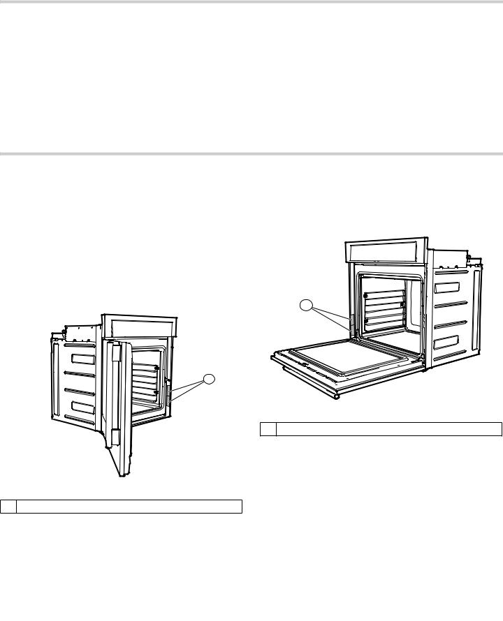
Aligning Side Hinge Oven Doors
Note: Only align the side hinge oven doors after the unit is fully installed into the cabinet.
Tip: The gap between the top of the closed oven door and the control panel (or upper door for lower cavities in double ovens) should be uniform from side to side.
To align side hinge door:
1.Check to see if the side hinge oven doors are properly aligned.
The door should pull itself closed smoothly when the striker engages the roller as the door is closed.
2.Fig. A-Door is too low if hinge side is above level. A bump will be felt when the striker comes in to contact with the realignment roller.
3.Fig. B-Door is too high if latch side is above level. Interference will be felt between the striker and the catch receiver. Door needs to move down on latch side.
$ |
% |
13
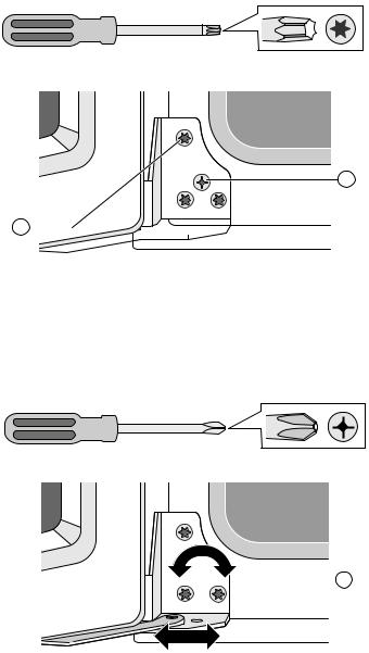
Side Hinge Door Alignment Procedure
1.Open the door to approximately 135°.
2.Using a Torx T20 screwdriver, loosen the three screws
(A) on the lower hinge by 1 to 2 full turns.
%
$

Note: All adjustments are made with the lower hinge only. The upper hinge is fixed in place and cannot be adjusted.
3.Using a #2 Phillips screwdriver, turn the cam screw
(B)right or left to adjust the hinge position in the desired direction.
 %
%
Note: 1mm of hinge movement (left or right) will move the door up or down approximately 1.5mm at the door catch.
4.Re-tighten the screws before closing the door to test. Be careful not to overtighten.
5.Check for proper door alignment. Repeat adjustment procedure as necessary.
14

Side Hinge Door Troubleshooting Guide |
|
|
|
|
|
Problem |
Additional Information |
Explanation |
Suggestion |
||
|
|
|
|
|
|
The door does not pull |
The side edge of the |
The installation is |
|
Check the installation |
|
itself closed and is difficult |
inner door (on the |
causing the side trim to |
|
of the unit in the |
|
to open. |
handle side of the door) |
be pushed too far |
|
cabinetry. Try moving |
|
|
appears to make contact |
inward. |
|
the unit in the cabinet |
|
|
with the unit’s side trim. |
|
|
|
towards the side of |
|
|
|
|
|
the hinges to allow the |
|
|
|
|
|
interfering side trim to |
|
|
|
|
|
open up. |
|
|
|
|
|
Adjust the location of |
|
|
|
|
|
the side trim screws to |
|
|
|
|
|
hold the trim away |
|
|
|
|
|
from the door. |
|
|
|
|
|
Check the cabinet |
|
|
|
|
|
opening that it is not |
|
|
|
|
|
too narrow. Widen the |
|
|
|
|
|
cutout as necessary. |
The door does not stay |
Very little force is |
The door catch |
|
To reset the |
|
closed. |
required to pull open the |
mechanism internal to |
|
mechanism, close the |
|
|
door. |
the door has |
|
door completely and |
|
|
|
inadvertently tripped |
|
while closed, push in |
|
|
|
while the door was open. |
|
firmly on the door |
|
|
|
|
|
|
handle until the |
|
|
|
|
|
mechanism resets. |
|
|
|
|
|
Open to test. |
|
|
|
|
|
|
The door does not close |
When closing the door |
|
The door alignment is |
|
Refer to Side Hinge |
on the striker smoothly. |
onto the striker, the |
|
too low to engage |
|
Door Alignment |
Once closed, the door |
door lifts itself upward. |
|
properly with the |
|
Procedure to raise the |
opens without incident. |
You will feel a slight |
|
striker. |
|
handle side of the |
|
|
Refer to Side Hinge |
|
door until it closes |
|
|
bump as the roller |
|
|
||
|
|
smoothly. |
|||
|
(internal to the door) |
|
Door Alignment |
|
|
|
|
|
|
||
|
hits the tip of the |
|
section for instruc- |
|
The door should open |
|
striker and lifts the |
|
tions. |
|
and pull itself closed |
|
door. |
|
|
|
smoothly without |
|
|
|
|
|
hearing or feeling |
If the door needs to lift |
|
Side Hinge Door Troubleshooting Guide |
|
substantially, the door |
interference. |
|
|
will no longer pull itself |
|
closed and |
|
assistance is required |
|
to push it closed fully. |
|
The door does not close on to the striker smoothly. Once closed, the door may also appear to stick while pulling the door open.
While trying to open the door, you feel an interference that catches the door and may prevent it from opening. A similar interference is felt when closing.
The door alignment is too high to engage properly with the striker.
Refer to Side Hinge Door Alignment section for instructions.
Apply pressure downward on the handle while pulling.
Refer to Side Hinge Door Alignment Procedure to lower the handle side of the door.
The door should open smoothly and pull itself closed smoothly without hearing or feeling interference.
15
Testing Operation
1.Turn on power at the breaker.
2.Test the oven mode.
Select the BAKE mode. See the Use and Care Manual for detailed operation instructions.
3.Verify that the oven light comes on and the oven begins to preheat.
4.Test the door lock.
Set the SELF CLEAN mode. Confirm that the door locks when the lock icon appears in the display.
5.If installing a double oven, test the second oven as well.
6.If any of the tests do not result as explained above, contact service for assistance. Otherwise, the installation is complete at this time.
Service
Before Calling Service
Do not remove rating label as it may void the product warranty.
Single Oven-Side Hinge
The rating labels (A) are opposite the door hinge. For left hinge doors, the rating labels will be on the door trim on the right hand side of the door. For right hinge doors, the rating labels will be on the door trim on the left hand side of the door.
$
Rating Label Location
A Rating Label
Model Number and FD Number
The model number and the FD number of your appliance are found on the rating label. Make a note of these numbers in the space below to save time in the event your appliance requires service.
Model # |
FD # |
Thermador |
800-735-4328 |
Customer Support |
|
|
|
Keep your invoice or escrow papers for warranty validation if service is needed.
Single Oven-Bottom Hinge
The rating labels (A) are located on the left hand side of the door trim.
$
Rating Label Location
A Rating Label
Model Number and FD Number
The model number and the FD number of your appliance are found on the rating label. Make a note of these numbers in the space below to save time in the event your appliance requires service.
Model # |
FD # |
|
|
Thermador |
800-735-4328 |
Customer Support |
|
|
|
Keep your invoice or escrow papers for warranty validation if service is needed.
16
Double Oven-Side Hinge
The rating labels (A) are opposite the door hinge. For left hinge doors, the rating labels will be on the door trim on the right hand side of the door. For right hinge doors, the rating labels will be on the door trim on the left hand side of the door.
$
Rating Label Location
A Rating Label
Model Number and FD Number
The model number and the FD number of your appliance are found on the rating label. Make a note of these numbers in the space below to save time in the event your appliance requires service.
Model # |
FD # |
|
|
Thermador |
800-735-4328 |
Customer Support |
|
Keep your invoice or escrow papers for warranty validation if service is needed.
Double Oven-Bottom Hinge
The rating labels (A) are at the left hand side of the door trim of the lower oven cavity.
$
Rating Label Location
A Rating Label
Model Number and FD Number
The model number and the FD number of your appliance are found on the rating label. Make a note of these numbers in the space below to save time in the event your appliance requires service.
Model # |
FD # |
|
|
Thermador |
800-735-4328 |
Customer Support |
|
Keep your invoice or escrow papers for warranty validation if service is needed.
17
Cabinet Requirements
Cabinet materials must be able to withstand the high heat associated with the use of an oven. It is the owner’s responsibility to review the suitability of cabinet materials prior to installation and use of the oven.
Under oven dimensions are provided as a general guideline and may be adjusted as needed based on a particular application. Consult a design professional for optimizing personal preferences.
Cabinet requirements vary depending on the model to be installed. Please consult the “Appliance and Cabinet Cutout Dimensions” chapter for the details pertaining to your particular model.
All models require:
¼” (6.4 mm) space between the side of the oven and an adjacent wall or cabinet door when installed at the end of a cabinet run.
A 2” diameter hole is required to run conduit to the junction box.
The junction box must be installed according to the locations specified and can be found in the individual dimension installation instructions found.
The cabinet base must be flat and capable of supporting the weight of your oven when in use (varies by model up to 429 lbs. (195 kg). See the appropriate weight for your model in the NOTICES area at the beginning of each individual model section.
Ensure that a recommended 1/4” (6 mm) minimum clearance gap is maintained on either side of the oven door with that of adjacent cabinetry, cabinet doors, walls, etc. to avoid incidental contact with the oven door throughout its entire range of motion.
Ensure that the cabinet floor structure properly supports the full weight of the oven from underneath. It is recommended that (2) 2x4 runners spanning front to back of the cabinet be installed and be adequately supported within the cabinet. The runners should be spaced apart to the full width of the oven such that they support the left and right edges of the oven base.
Note: When installing a side hinge oven, leave a minimum 10” (254 mm) clearance to allow the door to open.
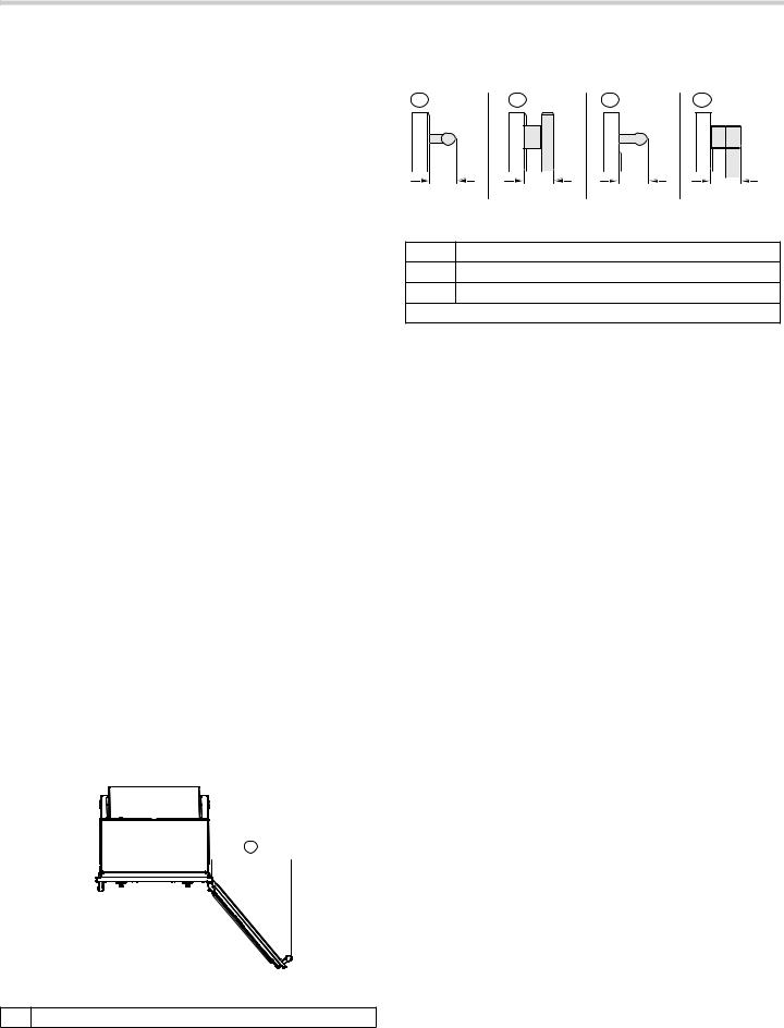
Door Handle Depth
$ |
% |
& |
' |
ò ó ïï ïï
PP
AMasterpiece Series Handle
BMasterpiece Series Side Hinge Handle
CProfessional Series Handle
DProfessional Series Side Hinge Handle
Note: Protrusion of handle from outer part of door. Does not include thickness of door.
$

 çʨʚ
çʨʚ 

PP
A Door Fully Open
18

Appliance and Cabinet Cutout Dimensions
Dimensions for Single Oven Units
NOTICES
A 2” diameter hole is required to run conduit to the junction box.
The cabinet base must be flat and capable of supporting a weight of at least 232 lbs (105 kg).
Under oven dimensions are provided as a general guideline and may be adjusted as needed based on a particular application. Consult a design professional for optimizing personal preferences.
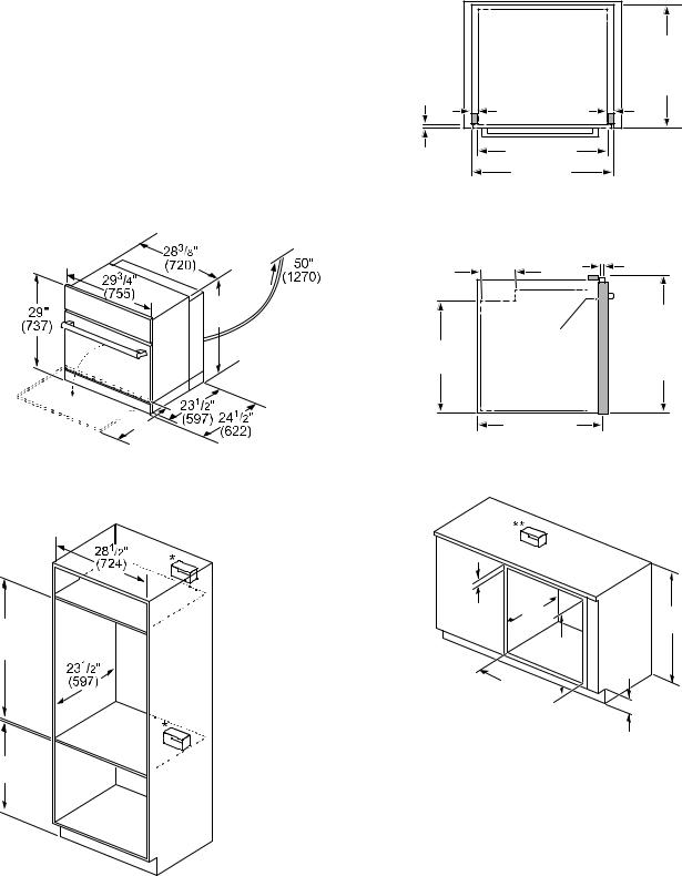
Single Oven Wall Mount Installation
Single Oven Right Hinge
PP
Single Oven Left Hinge
PP
Single Oven Bottom Hinge
PP
Single Oven Wall Mount Installation
ǫ
ë
PP
*For single ovens installed into a wall cabinet, the junction box may be located above, beneath, left or right of the unit within reach of the power cord.
**For oven installation in a wall cabinet, the control panel overlap is a minimum 3/8” (10mm) to max. 11/4” (25mm).
19
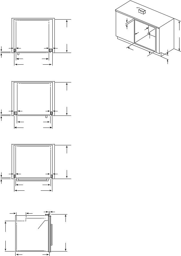
Single Oven Flush Mount Installation
Flush installation requires two side cleats to be attached inside the cabinet frame, recessed from the front.
Top View Right Hinge Door
|
|
ò |
|
|
|
|
|
ô |
ò |
IOXVK LQVHW |
|
UHYHDO |
UHYHDO |
GHSWK |
|
FOHDWV |
FOHDWV |
|
|
|
|
|
|
|
|
|
|
ò |
|
|
|
ô |
|
PP |
|
Top View Left Hinge Door
|
|
ò |
|
|
|
|
|
ò |
ô |
IOXVK LQVHW |
|
UHYHDO |
UHYHDO |
GHSWK |
|
FOHDWV |
FOHDWV |
|
|
|
|
|
|
|
|
|
|
ò |
|
|
|
ô |
|
PP |
|
Top View Bottom Hinge Door
|
|
ò |
|
|
|
|
|
ô |
ô |
IOXVK LQVHW |
|
UHYHDO |
UHYHDO |
GHSWK |
|
FOHDWV |
FOHDWV |
|
|
|
|
|
|
|
|
|
|
ò |
|
|
|
|
|
PP |
|
Side View-Right Hinge, Left Hinge and Bottom Hinge
|
|
|
|
|
|
|
|
|
UHYHDO |
ǩ |
|
|
|
|
FOHDWV |
|
|
IOXVK |
|
|
ǫ |
|
|
FXW RXW |
|
|
|
|
|
KHLJKW |
|
|
|
|
|
ò |
|
PP |
Dimensions for Under-Counter Installation
|
ê |
|
|
|
|
|
|
|
|
|
|
|
|
|
é
ê 

 ë
ë
PP
* Includes ¾” (19 mm) base plate.
**For single ovens installed under a cabinet, the junction box should be located to the right or left of the unit within range of the power cord.
20
Dimensions for Steam and Convection Oven Units
NOTICES
A 2” diameter hole is required to run conduit to the junction box.
The cabinet base must be flat and capable of supporting a weight of at least 232 lbs (105 kg).
Under oven dimensions are provided as a general guideline and may be adjusted as needed based on a particular application. Consult a design professional for optimizing personal preferences.
Steam and Convection Oven Wall Mount Installation Steam and Convection Oven Bottom Hinge
èʨʓʘèçʨʓʘ 
|
ʎʨʓʘ |
|
|
|
ʎʨʓʘ |
çʨʚ |
|
|
|
PP |
|
Wall Mount Installation
Steam and Convection Oven Flush Mount Installation Top View Bottom Hinge Door
|
|
|
|
|
|
|
|
ô |
ô |
IOXVK LQVHW |
|
UHYHDO |
UHYHDO |
GHSWK |
|
FOHDWV |
FOHDWV |
|
|
|
|
|
|
|
|
|
|
ò |
|
|
|
|
|
PP |
|
Side View Bottom Hinge
|
|
|
|
|
|
|
|
|
UHYHDO |
èʌʨʓʘ |
|
|
|
|
FOHDWV |
|
|
IOXVK |
|
|
ë |
|
|
FXW RXW |
|
|
|
|
|
KHLJKW |
|
|
|
|
|
|
|
PP |
Dimensions for Under Counter Installation
ê ʎʨʓʘ
ë çʨʓʘ
PP
*For single ovens installed into a wall cabinet, the junction box may be located above, beneath, left or right of the unit within range of the power cord.
|
ê |
|
|
|
|
|
|
|
|
|
|
|
|
|
|
|
èʨʓʘ |
|
|
|
|
ê |
|
|
|
ë ë |
|
|
|
PP
*Includes 3/4” (19 mm) base plate.
**For single ovens installed under a cabinet, the junction box should be located to the right or left of the unit within range of the power cord.
21
Dimensions for Steam and Convection Oven with Storage Drawer
NOTICES
A 2” diameter hole is required to run conduit to the junction box.
The cabinet base must be flat and capable of supporting a weight of at least 232 lbs (105 kg).
Under oven dimensions are provided as a general guideline and may be adjusted as needed based on a particular application. Consult a design professional for optimizing personal preferences.
Steam and Convection Oven with Storage Drawer Wall Mount Installation
Steam and Convection Oven with Storage Drawer
ʐʨʓʘ
çʨʚ |
|
|
PP |
|
Steam and Convection Oven with Storage Drawer Wall Mount Installation
Steam and Convection Oven with Storage Drawer Flush Mount Installation
Top View Bottom Hinge Door
|
|
|
|
|
|
|
|
ô |
ô |
IOXVK LQVHW |
|
UHYHDO |
UHYHDO |
GHSWK |
|
FOHDWV |
FOHDWV |
|
|
|
|
|
|
|
|
|
|
ò |
|
|
|
|
|
PP |
|
Side View-Steam and Convection Oven over Storage Drawer
çʨʓʘ |
|
|
|
|
|
|
|
|
UHYHDO |
ǩ |
|
|
|
|
FOHDWV |
|
|
IOXVK |
|
|
çʨʚ |
|
|
FXW RXW |
|
|
|
|
|
KHLJKW |
|
|
|
|
|
ò |
|
PP |
Steam Oven with Storage Drawer Under-Counter Installation
ʌʨʚ ʌʨʚ
ë
PP
*For single ovens installed into a wall cabinet, the junction box may be located above, beneath, left or right of the unit within range of the power cord.
|
ê |
|
|
|
|
|
|
|
|
|
|
|
|
|
é
ê 

 ë
ë
PP
* Includes ¾” (19 mm) base plate.
**For single ovens installed under a cabinet, the junction box should be located to the right or left of the unit within range of the power cord.
22
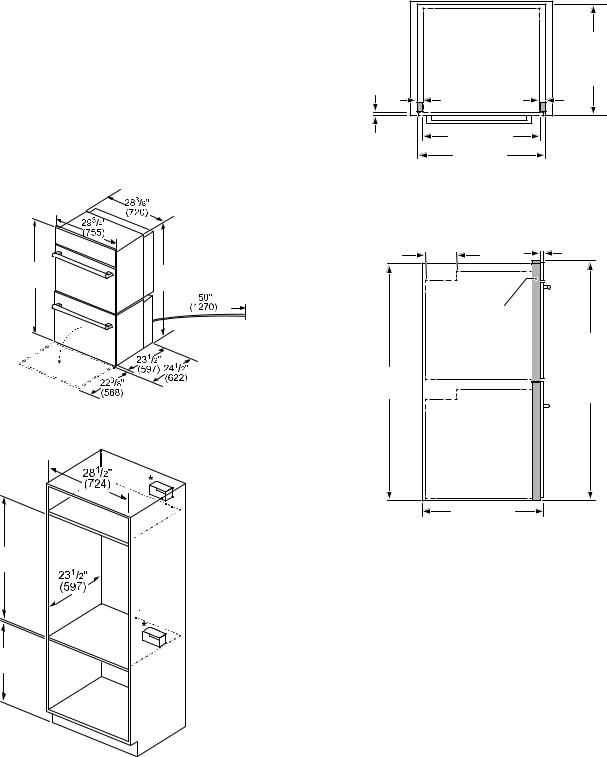
Dimensions for Double Oven Units
NOTICES
A 2” diameter hole is required to run conduit to the junction box.
The cabinet base must be flat and capable of supporting a weight of at least 429 lbs (195 kg).
Under oven dimensions are provided as a general guideline and may be adjusted as needed based on a particular application. Consult a design professional for optimizing personal preferences.
Note: When installing a side hinge oven, leave a minimum 10” (254 mm) clearance to allow the door to open.
$

 çʨʚ
çʨʚ 

PP
A Door Fully Open
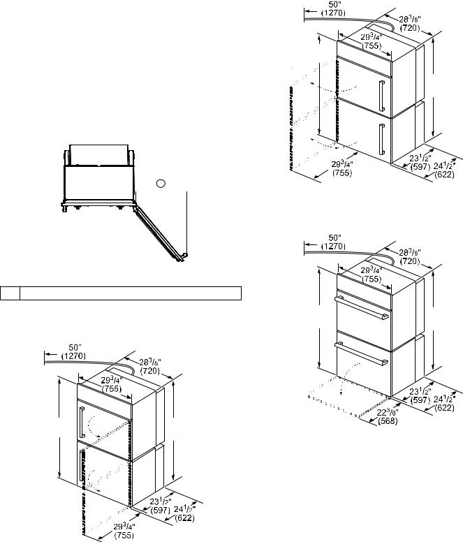
Double Oven Wall Mount Installation
Double Oven Right Hinge
èʨʓʘ |
ë |
|
|
PP
Double Oven Left Hinge
èʨʓʘ 


ë
PP
Double Oven Bottom Hinge
èʨʓʘ |
ë |
|
|
PP
23
Double Oven Wall Mount Installation
ê
ë ʎʨʚ
PP
Note: *Junction box may be installed above, right or left of the unit within reach of the power cord.
Double Oven Flush Mount Installation
Flush installation requires two side cleats to be attached inside the cabinet frame, recessed from the front.
Top View Right Hinge Door
|
|
ò |
|
|
|
|
|
ô |
ò |
IOXVK LQVHW |
|
UHYHDO |
UHYHDO |
GHSWK |
|
FOHDWV |
FOHDWV |
|
|
|
|
|
|
|
|
|
|
ò |
|
|
|
ô |
|
PP |
|
Top View Left Hinge Door
|
|
ò |
|
|
|
|
|
ò |
ô |
IOXVK LQVHW |
|
UHYHDO |
UHYHDO |
GHSWK |
|
FOHDWV |
FOHDWV |
|
|
|
|
|
|
|
|
|
|
ò |
|
|
|
ô |
|
PP |
|
Top View Bottom Hinge Door
|
|
ò |
|
|
|
|
|
ô |
ô |
IOXVK LQVHW |
|
UHYHDO |
UHYHDO |
GHSWK |
|
FOHDWV |
FOHDWV |
|
|
|
|
|
|
|
|
|
|
ò |
|
|
|
|
|
PP |
|
Side View-Right Hinge, Left Hinge and Bottom Hinge
ʐ ʓʘ |
|
|
|
|
|
|
|
|
UHYHDO |
|
|
FOHDWV |
|
|
|
ç ʓʘ |
|
|
|
|
èè ʓʘ |
IOXVK |
|
FXW RXW |
|
|
|
KHLJKW |
|
ò |
|
PP |
24
Dimensions for Combination Oven with Steam and Convection Oven Units
NOTICES
A 2” diameter hole is required to run conduit to the junction box.
The cabinet base must be flat and capable of supporting a weight of at least 429 lbs (195 kg).
Under oven dimensions are provided as a general guideline and may be adjusted as needed based on a particular application. Consult a design professional for optimizing personal preferences.
Combination Oven with Steam and Convection Oven Wall Mount Installation
ʎʨʚ |
é |
|
|
PP
Wall Mount Installation
çʨʚ èʨʚ
ë ë
PP
*Junction box may be installed above, beneath, right or left of the unit within range of the power cable.
Combination Oven with Steam and Convection Oven Flush Mount Installation
Top View Bottom Hinge Door
|
|
ò |
|
|
|
|
|
ô |
ô |
IOXVK LQVHW |
|
UHYHDO |
UHYHDO |
GHSWK |
|
FOHDWV |
FOHDWV |
|
|
|
|
|
|
|
|
|
|
ò |
|
|
|
|
|
PP |
|
Side View-Combination Oven with Steam and Convection Oven
è ʓʘ |
|
|
|
|
|
|
|
|
UHYHDO |
|
|
FOHDWV |
|
|
|
|
|
|
|
|
|
IOXVK |
|
FXW RXW |
|
|
|
KHLJKW |
|
ò |
|
PP |
25

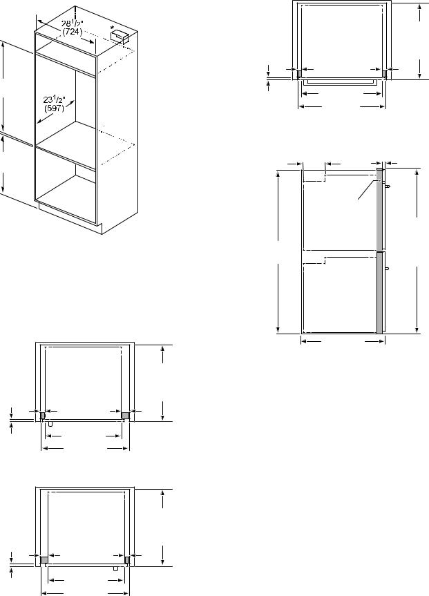
Dimensions for Combination Oven with Microwave or Speed Oven
NOTICES
A 2” diameter hole is required to run conduit to the junction box.
The cabinet base must be flat and capable of supporting a weight of at least 322 lbs (146 kg).
Under oven dimensions are provided as a general guideline and may be adjusted as needed based on a particular application. Consult a design professional for optimizing personal preferences.
Combination Oven with Microwave or Speed Oven
Ⱦ 
ë

ʎʨʓʘ
ê
|
Ⱦ |
PP |
|
|
ê 
ê  ê
ê 
ë
PP
*Junction box may be installed above, beneath, right or left of the unit within range of the power cable.
Combination Oven with Microwave or Speed Oven Flush Mount Installation
Top View Bottom Hinge Door
|
|
ò |
|
|
|
|
|
ô |
ô |
IOXVK LQVHW |
|
UHYHDO |
UHYHDO |
GHSWK |
|
FOHDWV |
FOHDWV |
|
|
|
|
|
|
|
|
|
|
ò |
|
|
|
|
|
PP |
|
Side View-Combination Oven with Microwave or Speed Oven
|
èʨʓʘ |
|
ʎʨʓʘ |
|
|
IOXVK |
|
|
|
|
|
FXW RXW |
|
|
|
KHLJKW |
|
ò |
|
PP |
26
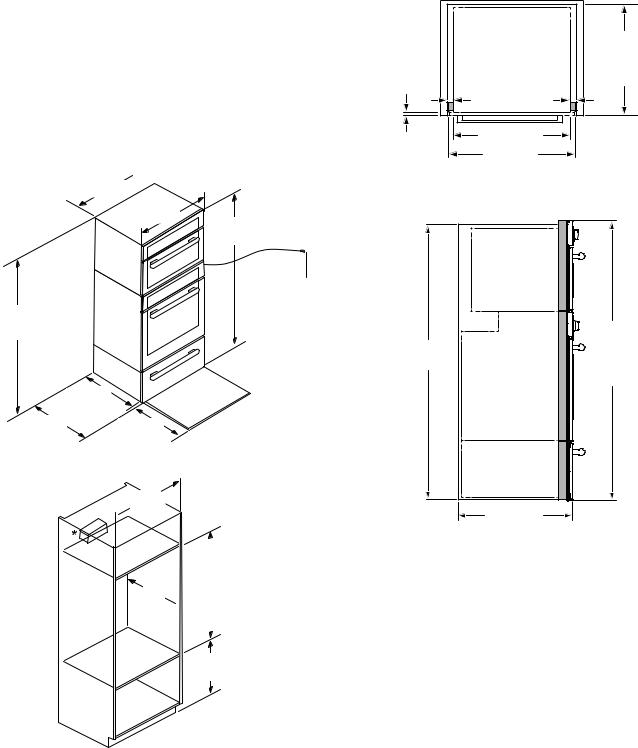
Dimensions for Triple Oven with Speed Oven and Warming Drawer
NOTICES
A 2” diameter hole is required to run conduit to the junction box.
The cabinet base must be flat and capable of supporting a weight of at least 429 lbs (195 kg).
Under oven dimensions are provided as a general guideline and may be adjusted as needed based on a particular application. Consult a design professional for optimizing personal preferences.
Single Oven with Speed Oven and Warming Drawer
Ⱦ 
ë
çʨʓʘ

ȿ
ê
|
Ⱦ |
|
|
|
P |
ê 
ë
ê
ë ë
PP
*Junction box may be installed above, right or left of the unit within range of the power cable.
Single Oven with Speed Oven and Warming Drawer Flush Mount Installation
Top View Bottom Hinge Door
|
|
ò |
|
|
|
|
|
ô |
ô |
IOXVK LQVHW |
|
UHYHDO |
UHYHDO |
GHSWK |
|
FOHDWV |
FOHDWV |
|
|
|
|
|
|
|
|
|
|
ò |
|
|
|
|
|
PP |
|
Side View-Single Oven with Speed Oven and Warming Drawer
|
ʌʨʓʘ |
ë |
|
IOXVK |
|
|
FXW RXW |
|
KHLJKW |
ò |
PP |
27
Loading...