


Installation Instructions |
|||
4 |
5 |
|
|
6 |
|
5 |
|
3 |
7 |
4 |
6 |
|
|
3 |
7 |
2 |
8 |
|
|
|
|
2 |
8 |
1 |
9 |
|
|
|
|
1 |
9 |
|
4 |
5 |
|
|
6 |
|
|
|
3 |
7 |
|
|
2 |
8 |
|
|
1 |
9 |
|
Thermador Glass Ceramic Cooktops |
|||
|
Models: CEF, CEP, CET |
|
|

Installation Instructions |
Models: CEF304, CEF365, CET304, CET365, CEP304, CEP365, CEP456 |
TABLE OF CONTENTS *
*NOTE: The blocked letters, such as A, shown below, refer to illustrations on Pages 2 & 4. Match these to the related text pages.
Overall Dimensions A.................................................................... |
2 |
|
Power Supply B ............................................................................ |
2 |
|
Cabinet Preparation and Clearances C ........................................ |
2, 3 |
|
Junction Box Location D................................................................ |
2 |
|
Countertop Cutout Dimensions E ................................................... |
2 |
|
Installing the Cooktop F ................................................................ |
4 |
|
Secure Cooktop to Countertop G ................................................... |
4 |
|
Solid Surface Countertop Installs H ................................................ |
4 |
|
Installation above a Single Oven I, J, K, and L .............................. |
4 |
|
Electrical Connection..................................................................... |
5 |
|
IMPORTANT: |
Save these instructions for Local Electrical Inspector’s use. |
|
INSTALLER: |
Please leave these Installation Instructions with this unit for the owner. |
|
OWNER: |
Please retain these instructions for future reference. |
|
READ AND SAVE THESE INSTRUCTIONS
OVERALL DIMENSIONS A
See Illustration A, Page 2. These dimensions are overall.
POWER SUPPLY B
ELECTRICAL POWER CONNECTION FOR
COOKTOP
Power Supply is dual rated: 240 Volts or 208 Volts, 4 wire, 60 Hz, with the following circuit breaker requirements: Models CEF304, CET304 or CEP304 at 30 Amps; Models CEF365, CET365 or CEP365 at 40 Amps or Model CEP456 at 50 Amps
Install a junction box (not supplied), below the counter top within 3 feet of flexible conduit (supplied) located at the right rear corner of the cooktop rough-in box.
JUNCTION BOX LOCATION |
D |
Plan the installation of the unit so that the location of the junction box is within 3 feet of the right rear of the cooktop bottom. It must be accessible from the front of the cabinet. (An exception to this location would be for a cooktop installation over a single electric oven In that situation, refer to Pages 4 and 5 and Figures I, J, K and L.
PAGE 1
Installation Instructions |
Models: CEF304, CEF365, CET304, CET365, CEP304, CEP365, CEP456 |
Models CEF304, CET304, CEP304: Width 31"
Models CEF365, CET365, CEP365: Width 37"
Models CEP456: Width 46"
All Models: |
Depth 21-5/8" |
|
|
Height above countertop: 1/4" |
|
A |
Overall Dimensions |
|
Cabinet |
Building |
|
Bottom |
||
Side Wall |
||
(unprotected) |
||
|
||
Building |
|
|
Back |
30" Min. |
|
Wall |
||
(762mm) |
||
|
|
Cooking |
C |
Surface |
Minimum Cabinet Clearances |
Models CEF304, CET304, CEP304: 30 Amp circuit breaker
Models CEF365, CET365, CEP365: 40 Amp circuit breaker
Models CEP456: 50 Amp circuit breaker
CEF, CET and CEP
Models: |
|
|
|
240 Volt, 4 Wire, 60 Hz |
||
B |
|
|
|
208 Volt, 4 Wire, 60 Hz |
||
Power Supply |
||||||
|
|
|
|
|
|
|
|
|
|
|
|
|
|
|
|
|
|
|
|
|
|
|
|
|
|
|
|
Conduit
(Approx. 3 Ft)
12" Approximate 

J Box
D |
Junction Box Location |
E
0LQXPXP
 6HWEDFN 'LVWDQFH
IURP IURQW HGJH RI FRXQWHU WRS WR IURQW HGJH RI FXWRXW
)ODW $UHD
 % )ODW $UHD
)ODW $UHD
&
)ODW $UHD
|
|
|
|
COUNTER CUTOUT DIMENSIONS |
|||
|
MODEL NOs. |
DIM |
Minimum in./(mm) |
Maximum* in./(mm) |
|||
|
|
|
|
|
|
|
|
|
CEF304,CEP304, |
B |
19 |
7/8 / (505) |
20 |
/ (508) |
|
|
CET304 |
C |
28 |
3/4 / (731) |
20 |
7/8 (530) |
|
|
|
|
|
|
|
|
|
|
CEF365,CEP365, |
B |
19 |
7/8 / (505) |
20/ (508) |
|
|
|
CET365 |
C |
34 3/4 / (883) |
35 |
/ (891) |
|
|
|
CEP465 |
B |
19 7/8 / (505) |
20 / (508) |
|
||
|
|
C |
43 |
3/4 / (1111) |
43 |
7/8/ (1114) |
|
*(For solid surface countertop installations, use maximum cutout dimensions and consult solid surface manufacturer for specific directions.)
PAGE 2
Installation Instructions |
Models: CEF304, CEF365, CET304, CET365, CEP304, CEP365, CEP456 |
CABINET PREPARATION AND |
C |
|
CLEARANCES |
||
|
||
|
|
To eliminate the risk of burns or fire by reaching over heated surface units, cabinet storage space located above the surface units should be avoided. If cabinet storage is to be provided, the risk can be reduced by installing a range hood that projects horizontally a minimum of 5 in. (127 mm) beyond the bottom of the cabinets. See C, Page 2.
This unit is designed for installation in the counter top with zero clearance to adjacent walls and projecting surfaces constructed of combustible materials. A 30inch minimum clearance is required between the top of the cooktop and the bottom of an unprotected cabinet. A 24 inch minimum distance is necessary when the bottom of the wood or metal cabinet is protected by not less than 1/4 inch of a flame retardant material covered with not less than No. 28 MSG sheet steel, 0.015 inch (0.4 mm) thick stainless steel, 0.024 inch (0.6 mm) aluminum, or 0.020 inch (0.5 mm) thick copper. Flame retardant materials bear the mark:
UNDERWRITERS LABORATORIES INC.
CLASSIFIED
MINERAL AND FIBER BOARDS SURFACE BURNING CHARACTERISTICS
Followed by the flame spread and smoke ratings., these designations are shown as “FHC (Flame Spread)/ (Smoke Developed)”. Materials with “O” flame spread ratings are flame retardant. Local codes may allow other flame spread ratings.
The minimum horizontal clearance from the sides and back edge of the cooktop to the adjacent vertical combustible walls is 0 Inches.
COUNTERTOP CUTOUT |
E |
|
DIMENSIONS |
||
|
The cutout dimensions depend upon whether the installation is for replacement, new construction, or installation in a solid surface countertop material, such as Surell™, Corian® etc. These materials require larger cutouts, use of heat reflective tape and rounded corners. Drawings G and H provide some guidelines only (see Page 4). Always consult the countertop manufacturer for specific Installation Instructions.
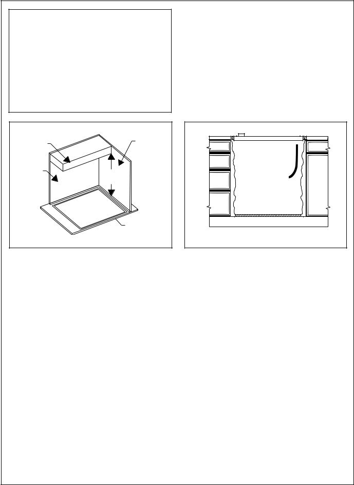
INSTALLING THE COOKTOP |
F |
WARNING:
DISCONNECT POWER BEFORE INSTALLING. BEFORE TURNING POWER “ON”, BE SURE THAT ALL CONTROLS ARE IN “OFF” POSITION
SECURE COOKTOP TO |
G |
COUNTERTOP |
The cooktop should be secured to the countertop using the hold-down brackets provided. Prior to inserting cooktop into cutout, turn cooktop upside down and attach brackets to the burner box using the washers and screws.
Place cooktop into cutout. Insert clamping screw into the bracket and secure cooktop to countertop.
Use a wood block to protect fragile countertop materials.
PAGE 3

Installation Instructions Models: CEF304, CEF365, CET304, CET365, CEP304, CEP365, CEP456
Swivel Conduit |
|
|
|
Burner Box |
Wood Block |
|
|
|
|
||
Connector |
|
|
|
Bracket |
|
|
|
|
|
|
|
Foam Tape |
|
|
|
|
|
Sealant |
|
|
|
|
|
F |
|
|
|
Adjusting |
|
|
|
G |
Screw |
|
|
Foam Tape Sealant |
|
Hold Down Brackets |
|||
|
|
|
|
|
|
Shows location of aluminum reflective tape
Tape top and vertical sides of cutout
H
Solid Surface Countertop Installation
Optional Cooktop Installation Over Single 30" Electric Oven
|
|
& |
|
& |
|
I |
Mark Center Lines of Cooktop Cutout |
|
|
|
|
7" Dia. Hole for 4" Dia. Vent Pipe (Duct for external vent oven only)
Oven frame 3/8" overlap
J Box for cooktop conduit
|
|
|
|
|
|
& |
|
|
|
|
|
|
|
|||
|
|
|
|
|
J Box for |
|
|
|
|
|
||||||
|
|
|
|
|
|
|
|
oven |
|
|
|
|
|
|||
|
|
|
|
|
|
|
|
conduit |
|
|
|
|
|
|||
|
|
|
|
|
|
|
|
|
||||||||
|
|
|
|
|
|
|
|
|
|
|
|
|||||
|
|
|
|
|
|
|
|
|
|
|
|
|
|
|
||
|
|
|
|
|
|
|
|
|
|
|
|
|
|
|
|
|
No frame |
|
|
|
|
|
|
|
|
|
|
|
|||||
|
|
|
|
|
|
|
|
|
|
|||||||
|
overlap |
|
|
|
|
|
|
|
|
|
|
|
||||
|
bottom |
|
|
|
|
|
|
|
|
Oven frame |
||||||
|
|
|
|
|
|
|
|
|
|
|
|
|
|
5/8" Overlap |
||
K |
|
|
|
|
|
|
|
|
|
|
|
|
|
Typ. |
||
|
|
Locations of Oven Junction Box and |
||||||||||||||
|
|
Vent Hole |
|
|
|
|
|
|
|
|
|
|||||
&
&
4" Nominal |
SR |
|
|
Toe Space |
SR |
|
SR |
J |
Mark Center Lines of S301, C301 or |
SC301 Oven and Cooktop Cutout |
|
|
|
|
3-5/8" Min. |
|
|
27-3/8" |
Cooktop |
|
|
|
|
|
|
|
Conduit |
|
|
|
Exposed edge must |
|
|
|
be a finish-cut |
|
|
3/4" |
|
4" Nominal |
|
|
|
Toe Space |
|
2 x 4 Supports |
|
L |
Vertical Opening of Oven Cutout |
||
PAGE4
Installation Instructions |
Models: CEF304, CEF365, CET304, CET365, CEP304, CEP365, CEP456 |
SOLID SURFACE COUNTERTOPS |
H |
Always consult the countertop manufacturer for specific instructions.
Countertops made from natural (i.e. granite and marble) or SOLID SURFACE MATERIALS, such as Surell™ and Corian®, require special cutout preparation and installation procedures. Follow the guidelines in preparing the cutout dimensions. Refer to Pages 2 and 3.
Install the cooktop as follows:
1.Round the cutout corners according to instructions from the countertop manufacturer.
2.Apply heat reflective tape (such as 3M™/Scotch® Aluminum Foil Tape #425 or #427) around the cutout so that it folds over the top and side surfaces. Be sure the tape extends beyond the outermost flange of the cooktop. All corners should also be covered with tape.
3.Attach brackets to the burner box using washers and screws provided. Use a wooden block underneath the countertop before tightening the bracket screws.
4.Center cooktop in the cutout to insure adequate clearance between the burner box and countertop edge. (A light pencil mark along the center of front edge and side edge of cooktop and counter will aid positioning of the cooktop in the center.)
5.Trim excess aluminum tape along the frame edges. BE CAREFUL not to scratch the countertop.
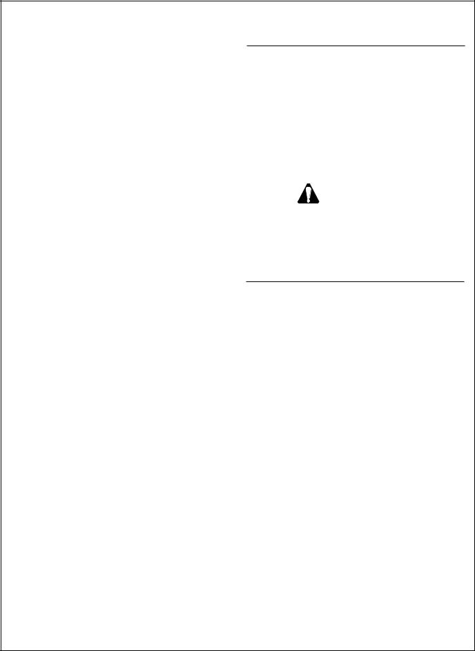
Installation above an oven, S301, SC301, C301, CM 301 (Optional) I, J, K, and L.
The cooktop can be installed over a single Thermador® electric oven. The cooktop should be located on the same center line as the under-the-counter single oven. If a single oven is installed under the cooktop, see Figure K for the location of the junction boxes.
NOTE: Thermador single oven Models S301, SC301, C301 and CM 301 installed under-the-counter with a Thermador® electric cooktop over it is a UL approved installation.
ELECTRICAL CONNECTION
1. Attach flexible conduit to the junction box.
2.Connect the cooktop lead wires to the junction box supply wires in proper phase:
For CEF, CET AND CEP models, connect black (L1) to black, red (L 2) to red, green wire to ground, white neutral to white.
NOTE: If the cooktop is installed and connected as specified above, it will be completely grounded in compliance with the National Electrical Code.
3.Remove everything from the cooktop surface and apply Cooktop Cleaning Creme (packaged with cooktop), as directed in Care & Use Manual, Page 14.
4.Turn on power supply.
5.Test operation.
CAUTION:
Your cooktop surface needs to be cleaned daily. Refer to the Care and Use section before using it for the first time.
PAGE5
 Loading...