

Page 1
D 194.8
Content
1. Functions
2. Sensor mounting in open areas
3. Sensor mounting in gutters, on rooftops and on satellite
systems
4. Connection diagrams
5. Commissioning
6. Display and pushbutton functions
7. Operation, menu and error codes
8. Technical data, safety instructions
Ice and Snow Detector Type 1773
for the TF-E System
Introduction
In cooperation with the moisture and temperature sensors of the TF-E system, the 1773 Ice and Snow Detector
is used for early detection of ice and snow and for keeping the monitored surface or gutter free by switching on
a defrosting device. One or two sensors can be connected to the 1773 Ice and Snow Detector. The sensor
function (temperature and/or moisture monitoring) and other settings can be defined for each sensor
individually. The individual parameters and measured values can be diplayed and changed in the menu using
the display and three operating buttons. An LED shows the current operating state.
The sensor type 3354 (or its predecessor 3351) can be used for gutters, flat rooftops or satellite systems. Open
areas such as driveways or parking lots can be monitored with the sensor types 3355 and 3356 (predecessors
3352 and 3353), which resist mechanical load such as cars driving over them.
Most ice and snow detection systems use exposed metal electrodes. Their disadvantage is that these
electrodes can accumulate dirt, suffer from corrosion or get short circuited by external conductive objects.
Therefore their sensors need periodical maintenance work in order to avoid that environmental influences impair
the accuracy of moisture measurement.
The TF-E system takes advantage of the increase of thermal capacity due to moisture, i. e. the availability of
water in liquid or solid form (snow, ice) on the sensor. With the help of a patented measurement and evaluation
method, the temperature variation with regard to the sensor is used to detect moisture on the sensor surface.
This guarantees a maintenance-free and secure operation.
1. Functions
If the sensor temperature is below the defined critical temperature limit, the moisture control is activated. If
moisture is detected, the heating system is switched on. If not, the moisture is measured again periodically. At
the earliest when the defined minimum heating time has expired, the heating system is switched off again if
there is no more moisture on the sensor.
In addition to the limit value of the critical temperature range (0 to +5 °C) a lower value can be set between -5
and –20 °C. This is useful because in case of very low outdoor temperatures there will no longer be any dripping
melt water or snow. If snow falls despite the extreme temperature, it will be dry, light and not slippery. In such a
case the heating would not be powerful enough to completely melt the snow on the surface. Thus the danger of
slippery conditions would rather be increased if the heating were switched on.
- 1 -
Page 2

Connecting the sensor inputs
In order to adapt to the desired monitoring functions, you can choose to wire the inputs in three different ways:
Operation with one sensor
The Type 33.. sensor is connected to sensor input 1 for temperature and moisture monitoring.
Operation with two sensors
Two sensors can be connected to the ice and snow detector: either two combi sensors for moisture/temperature
or one combi sensor and one temperature sensor. This type of operation is recommended in case of differences
in topography or areas with pronounced differences of sun and shadow.
The measured values are collected one by one. If one of the combi sensors indicates moisture, the heating of
the open area will be activated.
The relevant measurement functions of the sensors are set in the configuration menu "Sensor".
Slab idle temperature operation
A combi sensor and a temperature sensor are connected to the ice and snow detector. A Type 33.. sensor is
connected to sensor input 1 for temperature and moisture monitoring; a type 31.. temperature sensor is
connected to sensor input 2 in order to measure the outdoor temperature (also refer to "Slab idle temperature").
Moisture measurement
If the measured temperature falls below the set "high temperature limit", the sensor heating will heat up the
sensor surface and subsquently assess if the sensor is dry or moist. If the set moisture sensitivity is exceeded,
the heating is switched on for the set minimum heating time. After the minimum heating time has passed, there
will be another moisture measurement. If the sensor is still moist, the heating will remain switched on. If the
temperature measured in the sensor reaches the set "high temperature limit" during the second or further
measurements, the switch output will be switched off prematurely.
Note: Also for sensors which are only activated for moisture monitoring, the integrated temperature sensor must
be connected and operational because the sensor temperature is required for determining moisture. Therefore
there will also be an error message for these sensors if "only" the temperature measurement is impaired.
In order to avoid incorrect measurements, the supply voltage of the ice and snow detector is monitored before
and during moisture measurement. In case the value is outside the voltage area for which correct functioning is
guaranteed, there will be an error message (refer to chapter "Error codes").
The system automatically optimizes the duration of one measurement cycle depending on the type of sensor,
the supply voltage and the sensor temperature.
Ambient temperature of moisture sensors
Depending on the type of sensor, the ambient temperature cannot be measured during the moisture
measurement and for a certain time after the measurement. This is because the temperature of the integrated
temperature sensor is influenced by the moisture measurement. During this time the system works with the last
measured ambient temperature.
Slab temperature
If two sensors are used to measure the slab temperature, the relevant slab temperature is calculated according
to the following pattern (with a hysteresis of 0,5K each) :
- Both sensors above or below the range of the high to low temperature limit: The relevant slab
temperature is the average value of both measured values.
- Both sensors within the range of the high to low temperature limit: The relevant slab temperature is the
average value of both measured values.
- One sensor outside and one sensor within the range of the high to low temperature limit: The relevant
slab temperature is the value measured within this range.
- One sensor above and one sensor below the range of the high to low temperature limit: For the relevant
slab temperature an "-!-" is displayed as an indication that there is an installation or configuration problem
(slab heating is not activated).
In this way the moisture measurement is activated at the earliest possible point in time.
Slab idle temperature mode
In the operating mode "Slab idle temperature" a temperature and moisture sensor has to be connected to
sensor input 1 and a temperature sensor (Series 31..) has to be connected to sensor input 2 (terminals 6/7) in
order to measure the outdoor temperature. The sensor types need to be defined accordingly in the configuration
menu!
- 2 -
Page 3

As soon as the outdoor temperature is below the high temperature limit (within the range of the "high and low
temperature limit"), the slab temperature measured by the sensor at input 1 is kept at the level of the setpoint
value (with an hysteresis of 1K). Additionally the moisture is measured regularly. If moisture is detected, the
heating will be switched on. If there is no moisture, the slab temperature will be kept at the setpoint value for as
long as the outdoor temperature is below the temperature limit.
Emergency operation (not in the "Slab idle temperature" mode)
If two sensors are connected (moisture and temperature), the controller will switch to emergency operation in
case one of the two temperature or moisture measurement circuits is impaired and the corresponding function is
activated for both sensors in the "Sensor status". In this case the evaluations will only be made with one
measurement circuit. The LED indicating the operating mode will flash red/green in order to indicate the error.
Moisture value and setting of the moisture limit
The sensors determine the moisture value as a number (without measurement unit). It lies in the range from 1 to
99. The moisture value is determined by the sensor type, the present moisture and the installation situation. By
all means the optimum moisture limit should therefore be determined during installation. In doing so, the user's
preferences need to be taken into account, i. e. if the slab heating should already be switched on in case of very
little moisture or only if a certain amount of moisture has developed. The factory default setting of 50 can be
used as an indicator. If the moisture limit is set to 50, all measured moisture values above 50 lead to the result
"moisture detected" and trigger the heating unit.
Counter for operating hours
The ice and snow detector has a counter for operating hours with two display levels. The first level "Time Mtr 1"
can be reset to zero. In this way it can be monitored for how many hours the heating was switched on since the
last reset (e. g. during one heating period). The second level shows the operating time of the heating unit since
the controller has been taken into use. This level cannot be reset.
Invertible alarm output
In case of an error there is a voltage of 24V between the terminals of alarm output A+ and A-. In this way the
alarm may, for example, be detected by a central control centre via the type 1798 coupling relay.
The state of the alarm output may be inverted using the menu, i. e. in the normal state (no error) the alarm
output is supplied with 24V or in case of an error 0V. Like this the control centre may detect a power failure of
the system.
PC interface
The controller has an interface for connection to a PC. The optional connection cable and software are available
as accessories and allow for a display of all settings and measured values. Please contact us for more
information.
2. Sensor mounting in open areas (sensor type 3352, 3353, 3355 or 3356)
The sensors designed for use in open areas used by vehicles and pedestrians are cast in a body in brass GMs63. The sensors have a fixed supply line. For type 3352 it is fed into the sensor body from the bottom and for
type 3353 from the side. For types 3355 und 3356 the supply line can be variably fed into the body.
The sensors type 3352, 3355 and 3356 may be installed in a ground socket. When the open area is built, this
ground socket is placed into the surface without the sensor in such a way that there will be an even surface after
installation of the sensor. Refer to the mounting example below for detailled information.
Especially in case of surfaces which need a high processing temperature, such as poured asphalt (> 75 °C), the
fitting of a ground socket should be well provided for. In order to avoid that the ground socket sinks into a soft
surface later (e. g. in a sand bed for stone paving), it is recommended to create a firm footing for the socket (e.
g. by putting a concrete slab underneath it).
Note: A protective tube needs to be used for the sensor supply line. This is beneficial both during a new
installation and in case of a necessary replacement. Depending on the weight and material of the surface either
a plastic pipe or an armoured steel tube DN20 can be used. Make sure that the openings of the empty conduit
and the ground socket are securely closed during the construction of the open area to keep out building
material.
- 3 -
Page 4
When choosing the sensor's installation location, unfavourable circumstances such as aisles, shady areas,
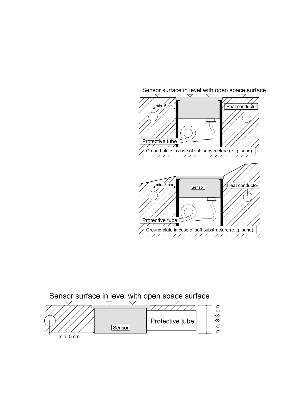
Installation in flat open areas
The sensor needs to be installed inside the area
to be monitored and heated in such a way that
the sensor surface is in level with the surrounding
surface material and the sensor surface remains
free. The sensor must not stick out of the open
area but can rather be a few mm lower so that
draining water is collected.
Installation in open areas with a slope
In case of slopes it needs to be made sure that
the sensor surface lies horizontally in order to
be able to collect snow or melt water.
warm air outlets in underground parking lots etc. need to be avoided. The sensor should be installed in a place
where the critical criteria "moisture and low temperature” causing the formation of ice are most likely to occur
first.
To make sure that the ice and snow detection system works properly, take care that the minimum
heating time is long enough so that melt water can moisten the sensor.
The sensor location must be chosen in such a way that the draining melt water runs onto the sensor's
measuring surface. This ensures that moisture is detected as long as there is any.
Installation in open areas with minimum construction height
The type 3353 sensor, which has a supply line at the side of the sensor case, or the type 3355 and 3356
sensors with a variable supply line location are particularly suited to open areas with a low construction height.
Take care not to damage the sensor when constructing the surface, e. g. by an excessive processing
temperature (>75 °C) or by mechanical load due to the use of compactors. Use a suitable protective tube (DN20
in plastic or armoured steel) to ease installation and protect the supply line.
- 4 -
Page 5
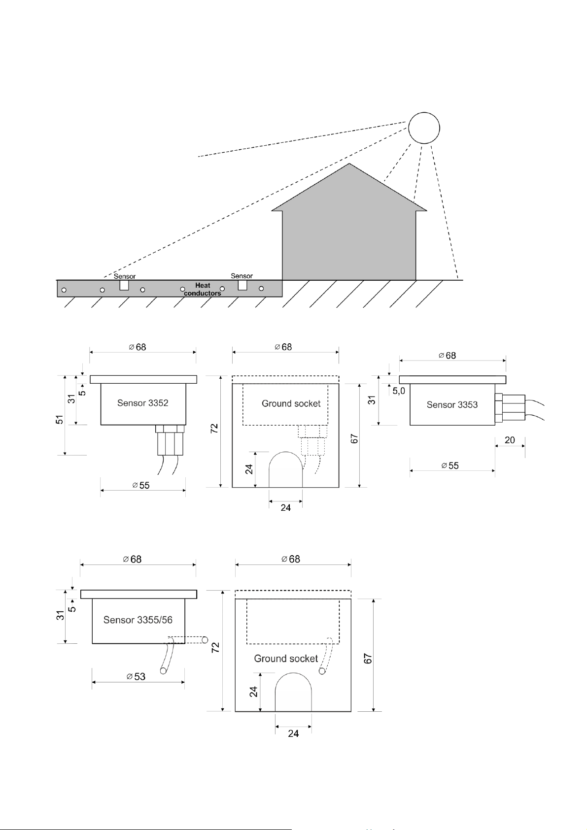
Installation example with two sensors
Two sensors can be connected to the snow and ice detector. In this way it is possible to optimally monitor large
or separated open areas, which may have different local conditions (such as sun in the southern part of the area
and shadow in the northern part or due to shading by a roof as in the illustration below).
Dimensions: Type 3352 and 3353 sensors [mm]
Dimensions: Type 3355 and 3356 sensors [mm]
- 5 -
Page 6
Technical data: Types 3352, 3353, 3355, 3356
3
1
2
5
1
4
2
6
Supply line: SL-Y11Y, length 6 m, 20 m, 50 m
resistant to microbes and oil according to DIN VDE 0472/9.21 para. 8036
Degree of protection: IP 68
Temperature resistance: –30 ...+75 °C
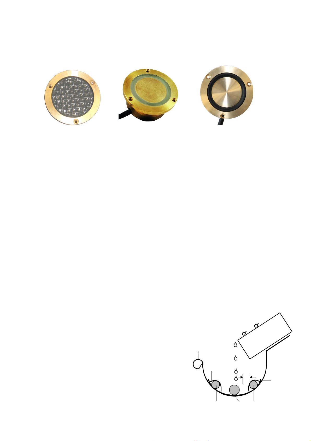
Sensor 3352/3353 Sensor 3355 Sensor 3356
Length of supply lines
The total length of the type SL-Y11Y supply line must not exceed 50 m. Provided that the clamping point
between the standard supply line and the extension is absolutely watertight and contact secure, the standard
supply lines may be extended by 6 m or 20 m up to the total length listed in the following overview. In order to
ensure operational safety, it is recommended to use a line extension only inside a building where it is dry.
Starting from the standard supply lines of 6 m or 20 m the total line length is as follows:
Standard line 6 m + Extension in 1.0 mm² (44 m) = Total length 50 m
Standard line 6 m + Extension in 1.5 mm² (66 m) = Total length 72 m
Standard line 6 m + Extension in 2.5 mm² (110 m) = Total length 116 m
Standard line 6 m + Extension in 4.0 mm² (176 m) = Total length 182 m
Standard line 20 m + Extension in 1.0 mm² (30 m) = Total length 50 m
Standard line 20 m + Extension in 1.5 mm² (45 m) = Total length 65 m
Standard line 20 m + Extension in 2.5 mm² (75 m) = Total length 95 m
Standard line 20 m + Extension in 4.0 mm² (120 m) = Total length 140 m
3. Sensor mounting in gutters, on rooftops and on satellite systems
(sensor type 3354)
The sensor must be installed in such a way that draining melt water runs off across the sensor. This ensures
that moisture is detected, if there is any.
In case the sensor is installed in a gutter or on a flat rooftop, it should be located as close as possible to the
downpipe or the drain In case it is used in connection with a parabolic aerial, the sensor should be placed
horizontally below the drip edge.
Installation position in the gutter
Explanation of the graphic:
1 cable tie for fastening the heat conductors
2 heat conductor
3 sensor 3354
4 distance of sensor and heat conductor minimum 2.0 cm
5 gutter
6 protruding roof surface
- 6 -
Page 7

Installation location in the gutter
The sensor has to be installed below the drip edge
and close to the downpipe in such a way that melt
water drips on the sensor. The heating cables, which
are also installed in the lower part of the roof surface
in the example on the right, ensure that a sufficient
area inside and above the gutter are kept free from
snow and ice. In this way the melt water can run off.
Installation location in case of satellite
systems
The sensor is fixed to the lower edge of the satellite
dish in order to detect melt water until the dish is free
from snow and ice. The heat conductors are fixed to
the back side of the dish and switched on until the
snow or ice in the dish are completely melted.
Fasten the sensor only with the supplied
fastening material (plastic)!
Dimensions: Type 3354 sensor [mm]
Side view (cross section)
Technical data: Type 3354
Supply line: SL-Y11Y, 6 m, 20 m, 50 m
resistant to microbes and oil according to DIN VDE 0472/9.21 para. 8036
Degree of protection: IP 68
Temperature resistance: –30 ...+75 °C
- 7 -
Page 8

4. Connection diagrams
Note for service cases: The sensors are delivered with a four-wire cable. In existing installations there may be
sensors with a five-wire cable. Note that in this case the black wire is not connected.
Important commissioning note related to wiring
The ice and snow sensors of the T-FE series come with a four-core cable. One pair of wires (colour of wires
either brown and blue or white and white-black) is needed for temperature measurement, the other one (colour
of wires red and red-black) for moisture measurement.
The connection diagrams above show which wire is to be connected to which terminal. To ensure a successful
operation it is essential to follow these instructions strictly.
- 8 -
Page 9

Prior to powering up it is strongly recommended to check the wiring at the sensor terminals of the socket with an
First Sensor
Second Sensor
Resistance
value
Temperature
sensor (see
instructions)
Resistance
value
Temperature
sensor (see
instructions)
Resistance
value
Moisture
sensor (see
instructions)
Resistance
value
Moisture
sensor (see
instructions)
infinite
resistance
(no
connection)
infinite
resistance
(no
connection)
°C
Ohm
°C
Ohm
°C
Ohm
-20
14.626
-8
8.132
+4
4.721
-18
13.211
-6
7.405
+6
4.329
-16
11.958
-4
6.752
+8
3.974
-14
10.839
-2
6.164
+10
3.652
-12
9.838
0
5.634
+12
3.360
-10
8.941
+2
5.155
+14
3.094
Type
Ohm
3351
25 - 40
3352
25 - 40
3353
25 - 40
3354
~ 80
3355
~ 53
3356
~ 72
The sensor cables connected to the T1/T1 und
T2/T2 terminals can be measured with the help
of an ohmmeter.
The table on the left shows the relationship
between sensor temperature and sensor
resistance.
For a fully functional moisture sensor the resistance
value between the two terminals M1/M1 or M2/M2 is:
ohmmeter before plugging the controller into the socket. The expected electrical resistance values can be found
below in the instructions in section "Characteristic values of sensors". With a single sensor connected, perform
the checks shown in the left column of the table, and with two sensors connected perform the checks in both
columns.
Do not connect a wire of a temperature measurement circuit to a terminal of a moisture measurement circuit! Do
not connect both circuits! This may cause the immediate destruction of the sensor and/or the controller. We
strongly recommend to check the wiring before inserting and powering up the controller. A damage of the
sensor or controller as a result of faulty wiring will not be accepted as a case of warranty.
Switching off the heating system
If there is a central switch-off function for the whole heating system, also the power supply of the ice
and snow detector must be included. If this is not the case, there is the danger that a snow and ice
condition is not detected when the heating system is switched on.
Characteristic values of sensors
In order to measure the sensor values, disconnect the ice and snow detector from voltage and remove it
from the socket!
Temperature sensor
Moisture sensor
- 9 -
Page 10

5. Commissioning
Setting the language
When the ice and snow detector is switched on for the first time, you will be asked to set the language for the
menu navigation. This language will be used as the menu language and saved as a factory default setting. The
language can be selected with the help of the '+' and '-' keys. 'SET' saves the setting, 'ESC' discards the change
and postpones it until the detector is switched on the next time.
Sensor and parameter configuration
A type 3354 sensor is preset in the factory default setting; all parameters are set to the usually suitable values.
If a type 3355/3356 sensor (or one of its predecessor types 3351, 3352 or 3353) is used or another sensor
arrangement (two sensors, slab idle temperature operation etc. ) is desired, the sensor type(s) need to be set in
the menu (more information in the chapters below). Additionally the parameters for the switch-on and switch-off
temperatures and the minimum heating time need to be adapted to the desired operating mode.
Setting the moisture limit
The limit for moisture detection is factory set to 50. With the help of a test measurement when the sensor is dry,
it can be determined if this value needs to be adapted. Depending on the requirement for an early or late
detection of moisture, the moisture limit should be set to 10 (early) to 20 (late) units higher than the value
determined during the "dry" test measurement. Note that the power consumption may rise in case of an "early"
setting.
If the heating is activated too early or too late in actual operation, the moisture limit should be corrected
accordingly. It is recommended to change the setting in steps of 5 until the system works in a satisfactory way.
Type 3354 sensor
If the sensor is installed in a gutter or a similar location, the factory default setting usually does not need to be
changed. If necessary, however, a test measurement can be done and the moisture limit can be adapted
accordingly.
Type 3355, 3356 sensor
As the sensor environment and the installation situation may influence moisture detection in case of slab
installations, it is highly recommended to make a dry test measurement up to 30 °C and adapt the moisture limit
according to the requirements (see above).
Type 3352, 3353 sensor
The same applies as for the type 3355/3356 sensor. Please note, however, that a dry test measurement will
only result in reliable values if the ambient temperature is below 5 °C.
Functional test of the sensors
Attention: In case of functional tests with simulated temperatures the following needs to be taken into account:
After a moisture measurement the moisture sensors (due to their functional principle) have inhibit times of
approx. 15 to 25 minutes (depending on the type) before the ambient temperature can be measured and of
approx. 20 to 30 minutes before the moisture can be measured again. The functions of the snow and ice
detector and of the sensors are adapted to this behaviour and to the slab and outdoor temperature which in
reality only change very slowly. If very quick temperature changes are simulated during a functional test or the
detector is reset by switching it off and back on, this may lead to faulty measurements and a temporarily
"unreasonable" reaction of the system.
In order to determine the current moisture value the menu "Sensor test" is used. In this menu the moisture
measurement can be started independently from the whole system and the measured moisture value can be
read. This can be done during a typical switch-on situation (temperature and moisture correspond to a typical
case of moisture) or with the help of a "dry" measurement during which the sensor surface is absolutely dry. In
case the dry measurement is done in the summer, it needs to be taken care that the sensor is protected from
direct sunlight during and at least 30 minutes before the measurement.
Functional test of the heating
The heating may be activated and deactivated manually for test purposes; refer to chapter "Operation, menu
and error codes".
- 10 -
Page 11

6. Display and pushbutton functions
Operating state indicator
The display on the front shows the following operating states:
Green flashing System initialization
Green System in service
Green/red flashing System in service, at least one sensor faulty (alarm active)
Red flashing System not in service (alarm active)
Red System manually switched off
Pushbutton functions
Set:
general function "Select" or "Confirm"
go from home display to main menu
select the currently displayed submenu
select the currently displayed module number
select the currently displayed parameter for modification
save the current setting
" + " or " – ":
general function "Modify"
go to the previous/next menu item
modify the displayed sensor number
modify the displayed setting
activate or deactivate the heating system
" + " and "- " at the same time:
general function "Abort" (ESC)
return to the previous menu
return to the home display from the main menu
abort the current parameter modification without saving
Display symbols
The device communicates with the user with the help of a display with two rows of eight characters each. The
following symbols are used, independent of the current menu selection:
" - " Parameter value is being read
" –x– " Value is (currently) undefined
" –– " Sensor loop impedance too high, e. g. due to open loop
" –– " Sensor loop impedance too low, e.g. due to short circuit
" ... " Secure function; "Yes" needs to be selected in order to start the function
" OK" Secure function successfully completed
"Err" Secure function terminated
"act" Execution of current function still active
Within a display row a parameter which can currently be changed is displayed with a flashing cursor.
Menu operation will be terminated three minutes after the last pushbutton action and the home display will be
shown.
In order to indicate the operating or switching modes, the following symbols are used:
" " Mode = Off
" " Mode = On
" ! " Mode = On, slab being preheated (refer to "Slab idle temperature")
7. Operation, menu and error codes
- 11 -
Page 12

Menu level 1
Explanation
Language --
Presetting of menu language
Home display
Menu level 1
Menu level 2
Menu level 3
Explanation
...°c 0
Active
Slab temperature, Remaining
heating time, Operating state
Basic
Config.
Language
Setting: language version
Sensor n
Typ
Setting: sensor type
Temp Hi
Lim. ..°c
Setting: high temperature limit
HeatTime
min. ...m
Setting: minimum heating time
back
Show
status
State
-----------
Display: operating mode ice and
snow detector
Error
Code x
Display: error code ice and snow
detector
Slab
Heating
Slab
Heat.
Display: heating on/off
Time Mtr
1: .h
Display: counter level operating
hours
Time Mtr
2: .h
Display: counter level operating
hours
Reset
Mtr1
Command: delete counter level 1
RemHeat
Tim ...m
Display: remaining heating time
Slab
T ...°c
Display: slab temperature
Outdoor
T---x-°c
Display: outdoor temperature
Status
Sensor
State S.
-----------
Display: operating mode sensor
Error
Code
Display: error code sensor
Sensor
T. ...°c
Display: sensor temperature
Ambient
T. ...°c
Display: ambient temperature
Direct functions
Manual activation/deactivation of the slab heating
From the home display the heating can be activated by pressing the"+" pushbutton for a least two seconds. The
heating duration corresponds to the minimum heating time. If the heating has already been active, the remaining
heating time will be reset to the minimum heating time.
By pressing the "-" pushbutton from the home display, the heating is switched off, no matter if the heating has
been switched on manually or automatically.
If the device is in the "Off" mode, the "+" and "-" pushbuttons have no effect.
Menu structure
ESC function: If you press the "+" and "–" pushbuttons at the same time, you will go back to the previous
menu from any menu or to the home display from the main menu.
Initial commissioning
Operation
- 12 -
Page 13

Home display
Menu level 1
Menu level 2
Menu level 3
Explanation
Last
Moist. -x
Display: last moisture value
InhibTim
Tmp. ..m
Display: inhibit time for temperature
measurement
InhibTim
MDet. ..m
Display: inhibit time for moisture
measurement
back
back
Test
HeatTime
Test
Command: start/stop for minimum
heating time
Sensor
Test
State S.
---------
Display: sensor state
Sensor
T. ..°c
Display: sensor temperature
InhibTim
MDet ..m
Display: blocking time for
measurement
Start
MDet
Command: start measuring test
Last
Moist. -x
Display: latest measured moisture
value
back
back
Configuration
Operat.
Mode
Setting: operating mode
Temp Hi
Lim. ..°c
Setting: high temperature limit
value
Temp Lo
Lim. ..°c
Setting: low temperature limit value
SlabIdle
Temp ..°c
Setting: slab idle temperature
Moisture
Limit xx
Setting: moisture limit, ice and
snow detectore
HeatTime
min. ...m
Setting: minimum heating time
Config.
Sensor n
Sensor
Typ xxxx
Setting: sensor type
Method
Meas. ----
Setting: measurement method of
sensor
Moisture
Limit -x
Setting: moisture threshold of
sensor
back
Invert
Alarm 0/1
Setting: alarm output
back
Administration
Language
--
Setting: language version
Temp.
Units -
Setting: temperature unit
Factory
Def.
Reset to "factory default settings"
SW-Vers.
--.--
Display of software version
Internal
Status
Display of internal status
back
back
back
- 13 -
Page 14

Menu structure
Display
Explanation
+xx° yyy
zzzzzzzz
xx = effective slab temperature
yyy = remaining minimum heating time (0 if heating according to demand or heating off)
zzzzzzzz = current state of the ice and snow detector
Display
Explanation
Basic
config.
Opens the basic configuration menu
Show status
Opens the menu for the display of the current measured values and states
Test
Opens the menu to start/stop the minimum heating time and to start a sensor measurement
Configu-
ration
Opens the configuration menu for the heating and the sensors
Administra-
tion
Opens the administration menu for the system
Back
Return to Home display
Display
Explanation
Factory
default
Settings
Language
xx
Displays the set menu language; adapt setting with "Set" and then
"+" / "-"; save with "Set".
refer to "Initial
installation"
DE, EN,
FR, IT, NL,
CZ, PL
Sensor 1
Typ xxxx
Displays the setting of the connected sensor type for sensor 1;
adapt setting with "Set" and then "+" / "-"; save with "Set". When
saving the sensor type, the appropriate measurement method of
sensor 1 is set automatically to the method specified for the sensor
and the sensor state is reset automatically.
3354
3351
3352/53,
3354,
3355
3356
----
Temp Hi
Lim. xxx°
Displays the high temperature limit; adapt setting with "Set" and
then "+" / "-"; save with "Set".
+3°C
0° to +5°C
HeatTime
min.xxxm
Displays the set minimum heating time; adapt setting with "Set"
and then "+" / "-"; save with "Set". Can be set in steps of 10.
90 min.
30 to
600 min.
back
Returns to Main menu
Display
Explanation
State
--------
Displays operating state of ice and snow detector
Error
Code xx
Displays the current error code of the ice and snow detector (0 =
no error, refer to "Error codes")
Slab
Heating
Displays switching state of heating and operating hour counter
RemHeat
Tim xxxm
Displays the remaining heating time (0 if heating according to
demand or slab heating off)
Slab
T---,-°
Displays the effective slab temperature
Outdoor-
T---,-°
Displays the latest measured outdoor temperature (measured
value only available in Slab idle temperature mode)
1. Home display
2. Main menu
3. Basic configuration menu
4. Show status menu
- 14 -
Page 15

Status
Sensor n
Opens menu to display sensor n (after the first "Set" select n,
select sensor with "+" / "-" and then press "Set" again)
Back
Returns to Main menu
Display
Explanation
HeatTime
Test x
Displays the switching state of the slab heating; adapt setting with
"Set" and then "+" / "-"; save with "Set".
Select " " to interrupt the heating time, select " " to start again.
Sensor
Test n
Opens the menu for testing sensor n (after the first "Set" select n,
call sensor with "+" / "-" and then press "Set" again)
Back
Returns to Main menu
Display
Explanation
Factory
default
Settings
Operat.
Mode x
Displays the operating mode; adapt setting with "Set" and then "+"
/ "-"; save with "Set";
" " = system out of service,
" " = system in service,
" !" = system in service with additional function "Slab idle
temperature"
" " =
System in
service
" "
" "
" !"
Temp Hi
Lim. xxx°
Displays the high temperature limit; adapt setting with "Set" and
then "+" / "-"; save with "Set".
3°C
0 to 5°C
Temp Lo
Lim. xxx°
Displays the low temperature limit; adapt setting with "Set" and
then "+" / "-"; save with "Set".
-15°C
-20°C to
-5°C
SlabIdle
Temp---°
Displays the targeted slab idle temperature ; adapt setting with
"Set" and then "+" / "-"; save with "Set".
- 5°C
-15 to
+ 5°C
Moisture
limit xx
Displays the set moisture limit ; adapt setting with "Set" and then
"+" / "-"; save with "Set". Can be set in steps of 5.
5 = very sensitive sensor, little moisture required to trigger heating
(might cause continuous)
95 = very insensitive sensor; sensor must be immersed in water to
detect moisture (might cause no moisture detection at all)
50
5 to 95
HeatTime
min.xxxm
Displays the set minimum heating time ; adapt setting with "Set"
and then "+" / "-"; save with "Set". Can be set in steps of 10.
90 min.
30 to 600
min.
Config.
Sensor n
Opens the menu to configure sensor n (after the first "Set" select n,
call sensor with "+" / "-" and then press "Set" again)
1
1 or 2
Invert
Alarm
Invert alarm output
0
0 normal
1 invert.
Back
Returns to Main menu
Display
Explanation
Factory
default
Settings
Language
xx
Displays the set menu language; adapt setting with "Set" and
then "+" / "-"; save with "Set".
refer to "Initial
installation"
DE, EN,
FR, IT, NL,
CZ,PL
Temp
Units X
Displays the set temperature unit; adapt setting with "Set" and
then "+" / "-"; save with "Set".
°C
°C or °F
Factory
Def. ...
Restores all parameters to factory default settings. Adapt
setting with "Set" and then "+" / "-". After selecting "Yes" and
5. Test menu
6. Configuration menu
7. Administration menu
- 15 -
Page 16

setting with "Set" there will be a security prompt and after
confirming with "+" an acknowledgement will be displayed (OK).
SW-Vers.
Displays the software version
Internal
Status
Information only for the manufacturer
Back
Returns to Main menu
Display
Explanation
Slab Heat.
--------
Operating state of the slab heating (On/Off)
Time Mtr 1
Operating hour counter for heating 1, can be reset
Time Mtr 2
Operating hour counter for heating 2, cannot be reset
Reset Mtr 1
Reset counter 1 and start counter again from 0
Display
Explanation
State S.
--------
Displays operating state of selected sensor
Sensor
T.xxx,x°
Displays current temperature of selected sensor
InhibTim
MDet xxm
Displays remaining time before the next moisture detection cycle can begin
Start
MDet ...
Starts moisture detection for the selected sensor. Adapt setting with "Set" and then "+" / "". After selecting "Yes" and setting with "Set" an acknowledgement will be displayed (OK).
Only possible if measuring method "F" or "T+M" are set and no moisture measurement is
ongoing for another sensor. The inhibit time until the next measurement is interrupted
when this command is given. .
Last
Moist. xx
Displays the last measured moisture value of the selected sensor
back
Returns to Test menu
Display
Explanation
Factory
default
Settings
Sensor
Typ xxxx
Displays the setting of the connected sensor type for the selected
sensor; adapt setting with "Set" and then "+" / "-"; save with "Set".
When saving the sensor type, the appropriate measurement method
of the selected sensor is set automatically to the method specified for
the sensor and the sensor state is reset automatically.
3354
3351,
3352/53,
3354,
3355,
3356
31xx,
---
Method
Meas. xxx
Displays the setting of the measurement method for the selected
sensor; adapt setting with "Set" and then "+" / "-"; save with "Set".
"OFF" = sensor not in service,
" T " = only temperature,
" M " = only moisture,
"T+M" = temperature and moisture
The measurement methods "M" and "T+M" are not available for
temperature-only sensors (depending on the set sensor type). When
saving the measurement method, the sensor state is reset
automatically.
T+M
T+M,
T,
M,
Off
8. Status of slab heating
9. Sensor test
10. Sensor configuration
- 16 -
Page 17

Moisture
limit xx
Displays the set moisture limit for the selected sensor; adapt setting
with "Set" and then "+" / "-"; save with "Set".
Setting "-x" = the moisture limit set in the "Configuration" menu will be
used.
-X
-X to 95
back
Returns to Configuration menu
Error code
Description
Possible cause
1
Slab/gutter temperature cannot be determined;
all active temperature sensors report
temperature measurement failure.
• see sensor error code 1 (slab/gutter sensors
only)
• internal detector failure
2
Outdoor temperature required but not available
(slab idle mode only);
outdoor temperature sensor reports
temperature measurement failure.
• see sensor error code 1 (outdoor temperature
sensor only)
• internal detector failure
4
Moisture cannot be determined;
all active moisture sensors report temperature
measurement and/or moisture detection failure.
• see sensor error codes 2 or 4 respectively
• temperature loop of affected sensor faulty
• internal detector failure
8
Configuration problem
• no sensor defined for temperature
measurement
• no sensor defined for moisture detection
• slab idle mode enabled but no valid sensor
defined for outdoor temperature measurement
Error code
Description
Possible cause
1
Temperature sensor faulty
• temperature detector inside the sensor faulty
• internal detector failure
• open loop or short circuit in sensor cable
2
Supply voltage prior to start of the last
moisture detection cycle not within the defined
voltage range; detection cycle was not started.
• detector supply voltage more than + 10 %
above rated voltage
• detector supply voltage more than - 15 %
below rated voltage
• internal detector failure
4
Last moisture measurement faulty
• supply voltage too low during last moisture
detection cycle
• open loop or short circuit in sensor cable
• moisture detector inside the sensor faulty
• internal detector failure
8
Internal failure during last moisture
measurement
• configuration problem
• internal detector failure
16
Internal failure during interval between two
moisture detection cycles
• current > 25 mA although no detection cycle
is active on any sensor
• internal detector failure
32
Measurement is not executed because
measurement values are not meaningful or in
order to avoid damage to the sensor.
• temperature too high (> 30 °C) when
measurement cycle begins
64
Measurement is aborted to avoid damage to
the sensor.
• temperature too high (> 55 °C) during the
measurement
Error codes
In case of a failure, the menu "Show Status” will display an error code for the detector or the sensor(s). The
value "0” indicates that currently there is no error. The error codes are explained in the following tables. If more
than one error condition is active at any one time the display will show the sum of the related error codes (e. g.
error 1 and error 4 active at the same time will cause an error code 5 to be displayed).
a) Ice and snow detector
Note: As long as a single sensor failure does not cause the entire ice and snow detection system to fail, this will
not be shown as a system error in one of the above error codes. In this case please check the error codes of the
individual sensors.
b) Sensors
- 17 -
Page 18

Note: The sensor error codes 2, 4 and 8 will only be set during a moisture detection cycle and will remain visible
at least until the completion of the next moisture detection cycle of the affected sensor. This is even the case if
no more moisture detection cycles are started because the slab/gutter temperature is outside the active
temperature window. To reset the error code after fixing the problem, start a test measurement from the test
menu (menu "Test/Sensor X").
- 18 -
Page 19

Rated voltage
230 V~ ± 6%, 50 Hz
Power consumption
approx. 10 VA
Type of moisture sensor
tekmar 3354, 3355, 3356 (also predecessors 3351, 3352 and 3353)
Type of temperature sensor
tekmar Series 31
Number of sensors
1 or 2
Heating output
low-voltage relay, switching capacity max. 6 A, 250 V~
Alarm output
SELV 24 V= 20%, load capacity 15 mA, short-circuit protected
Ambient temperature
0 to +50 °C, no condensation; sensor –30...+75 °C
Storage temperature
-10 to +60 °C, no condensation; sensor –30...+75 °C
Degree of protection
IP 20; sensor IP 68 (according to EN 60529)
Class of protection
II according to DIN 57700, when installed in distribution cabinet
Pollution degree
2 (normal)
Space required
6 HP according to DIN 43880
Mounting
on mounting rail 35 mm according to DIN EN 60715
Weight
approx. 0,4 kg
Standards
DIN EN 60730-1, DIN EN 730-2-9
Heat and fire resistance
category D
Ball pressure test
+ 125 °C
Rated surge voltage
4 kV
Action type
type 1B
Rated power and load for EMC
emission test
230 V~, load 0,5 A
8. Technical data, safety instructions
Dimensions [mm]
Safety and functional instructions
Only qualified specialists may install the devices. The relevant VDE regulations must be observed. According to
VDE guideline 0100 cables carrying low voltage must be routed separately, away from cables carrying safety
extra low voltage. In case an inductive load (for example a contactor) is connected, it is possible that additional
measures to elimintate EMC interference must be taken during installation.
Many electronic devices may cause interference which may cause errors in other devices despite all technical
precautions. If the snow and ice detector is affected by such an error and does not react at all or faultily,
switching the power supply on and off often solves the problem. The device can also be reset by switching the
upstream circuit breaker off for approximately 10 seconds. In most cases the device functions without problems
after the reset. If this is not the case, contact the tekmar Service.
- 19 -
Page 20

Notes
0716
tekmar Regelsysteme GmbH Tel +49 201 48611-0 mail@tekmar.de
Möllneyer Ufer 17 Fax +49 201 48611-11 www.tekmar.de
D-45257 Essen
© Copyright tekmar Regelsysteme GmbH 2017, subject to change
- 20 -
 Loading...