

VIDEO
COMMUNICATION
SERVER
ADMINISTRATOR
GUIDE
Introduction
D 14049.01
D 14049.01
07.2007
Getting
Star ted
System
Overview
System
Configuration
Software version X1.0
D14049.01
July 2007
H.323 & SIP
Configuration
Registration
Control
1
Zones and
Neighbors
Call
Processing
Firewall
Traversal
Bandwidth
Control
Maintenance
Appendices
TANDBERG VIDEO COMMUNICATION SERVER
ADMINISTRATOR GUIDE
VIDEO
COMMUNICATION
SERVER
What’s in this
ADMINISTRATOR
GUIDE?
Disclaimer, Copyrights and License Agreements 8
Safety Instructions and Approvals 9
Environmental Issues 10
Introduction 12
About the TANDBERG Video Communication Server ................12
Main Product Features .......................................................... 12
Standard Features ..............................................................12
Optional Features ...............................................................12
About this Administrator Guide .............................................. 12
Getting Started 13
What’s in the Box? ................................................................13
Connecting the Cables .......................................................... 13
Installation Site Preparations .................................................13
General Installation Precautions ............................................13
Powering on the VCS ............................................................. 14
Initial Configuration via Serial Cable ....................................... 14
System Administrator Access................................................. 15
About Administrator Access .................................................15
Configuring Administrator Access ........................................15
Security Considerations ......................................................15
Administrator Account Password ..........................................15
Default Administrator Password ...................................... 15
Changing the Administrator Password .............................15
Resetting the Administrator Password .............................15
Session Timeout .................................................................15
Root Account ..................................................................... 15
Using the Web Interface ...................................................... 16
Suppor ted Browsers ....................................................... 16
Using the Command Line Inter face (CLI) .............................. 17
Viewing System Overview 18
Viewing the Over view Page .....................................................18
Understanding the Overview Page .......................................... 18
System Configuration 19
System Administration Configuration ...................................... 19
Configuring System Settings ................................................19
About the System Name .....................................................19
About Admin Access settings .............................................19
Ethernet Configuration ...........................................................20
Configuring Ethernet Settings ..............................................20
About Ethernet Speed .........................................................20
IP Configuration ....................................................................21
Configuring IP Settings ........................................................21
About IPv4 to IP v6 Gatewaying ............................................21
DNS Conf iguration .................................................................22
Configuring DNS Settings ....................................................22
About DNS Ser vers .............................................................22
About the DNS Domain Name ..............................................22
NTP Configuration .................................................................23
Configuring NTP Settings .....................................................23
About the NTP Server ..........................................................23
Setting the Time Zone .........................................................23
SNMP Configuration ..............................................................24
Configuring SNMP Settings..................................................24
About SNMP Settings ..........................................................24
External Manager Configuration .............................................25
Configuring External Manager Settings ................................25
About the External Manager ................................................25
Backing up Configuration Settings .........................................26
Introduction
Introduction
D 14049.01
D 14049.01
07.2007
Getting
Star ted
System
Overview
System
Configuration
H.323 & SIP
Configuration
Registration
Control
2
Zones and
Neighbors
Call
Processing
Firewall
Traversal
Bandwidth
Control
Maintenance
Appendices

Table of Contents
TANDBERG VIDEO COMMUNICATION SERVER
ADMINISTRATOR GUIDE
Logging 27
Logging Overview .................................................................. 27
About Logging ..................................................................... 27
About Remote Log ging ........................................................ 27
Enabling Remote Logging .................................................... 27
About Event Log Levels ....................................................... 27
Setting the Event Log Level ................................................. 27
Event Log .............................................................................. 28
Viewing the Event Log ......................................................... 28
Event Log Format ................................................................ 28
Message Details Field ......................................................... 28
Events Log ged at Level 1 ....................................................... 29
Events Log ged at Level 2 ....................................................... 30
Events Log ged at Level 3 ....................................................... 30
Event Data Fields .................................................................. 31
Working with H.323 33
H.323 Overview..................................................................... 33
About H.323 on the VCS ..................................................... 33
Using the VCS as an H.323 Gatekeeper ............................... 33
Configuring H.323 Ports ...................................................... 33
H.323 Endpoint Registration .................................................. 33
Overview ............................................................................ 33
Registration Conflict Mode .................................................. 33
Auto Discover ..................................................................... 33
Time to Live ........................................................................ 33
Call Time to Live ................................................................. 33
Configuring H.323 ................................................................. 34
Working with SIP 35
SIP Overview ......................................................................... 35
About SIP on the VCS .......................................................... 35
Using the VCS as a SIP Registrar ......................................... 35
Proxying Registration Requests ....................................... 35
SIP Registration Expiry ........................................................ 35
Using the VCS as a SIP Prox y Ser ver .................................... 35
SIP protocols and ports ....................................................... 35
Configuring SIP - Registrations, Protocols and Ports ................ 36
Configuring SIP - Domains...................................................... 37
Interworking 38
Overview ............................................................................... 38
About Interworking .............................................................. 38
Configuring Interworking ........................................................ 38
Registration Control 39
Registration Overview ............................................................ 39
Endpoint Registration .......................................................... 39
Registrations on a VCS Border Controller ............................. 39
MCU, Gateway and Content Server Registration ................... 39
Finding a VCS with which to Register .................................... 40
SIP ................................................................................ 40
H.323 ............................................................................ 40
Authentication ....................................................................... 41
About Authentication ........................................................... 41
Configuring Authentication .................................................. 41
Authentication using an LDAP Ser ver .................................. 42
Configuring the LDAP Server Directory ............................. 42
Securing the LDAP Connection with TLS ......................... 42
Alias Origin Setting ......................................................... 42
Configuring LDA P Server settings .................................... 43
Authentication using a Local Database ............................... 44
Configuring the Local Database ...................................... 44
Registering Aliases ................................................................ 45
About Alias Registration ...................................................... 45
H.323 Alias Registration ................................................. 45
SIP Alias Registration ..................................................... 45
Attempts to Register using an E xisting Alias ......................... 45
H.323 ............................................................................ 45
SIP ................................................................................ 45
Allow and Deny Lists ............................................................. 46
About Allow and Deny Lists ................................................. 46
Patterns and Pat tern Types ............................................. 46
Activating use of Allow or Deny Lists .................................... 46
Managing Entries in the Allow List ....................................... 47
Managing Entries in the Deny List ........................................ 48
Managing Zones, Neighbors and Alternates 49
Overview ............................................................................... 49
About your Video Communications Network.......................... 49
Example ............................................................................. 49
Local Zone and Subzones ...................................................... 50
About the Local Zone and its Subzones ............................... 50
Configuring the Local Zone and its Subzones ....................... 50
Zones ................................................................................... 51
About Zones ....................................................................... 51
ENUM Zone ........................................................................ 51
DNS Zone ........................................................................... 51
Traversal Client Zone........................................................... 51
Neighbor Zone .................................................................... 51
Traversal Server Zone ......................................................... 51
Default Zone ....................................................................... 51
Adding Zones ........................................................................ 52
Configuring Zones ................................................................. 52
Configuring Zones - All Types ................................................. 53
Configuring Neighbor Zones ................................................... 54
Configuring Traversal Client Zones ......................................... 55
Configuring Traversal Ser ver Zones ........................................ 56
Configuring ENUM Zones ....................................................... 57
Configuring DNS Zones .......................................................... 57
About Alternates ................................................................... 58
Configuring Alternates ........................................................... 58
Setting up a Dial Plan ............................................................ 59
About Dial Plans ................................................................. 59
Flat Dial Plan ................................................................. 59
Structured Dial Plan ....................................................... 59
Hierarchical Dial Plan ..................................................... 59
Introduction
Introduction
D 14049.01
07.2007
Getting
Star ted
System
Overview
System
Configuration
H.323 & SIP
Configuration
Registration
Control
3
Zones and
Neighbors
Call
Processing
Firewall
Traversal
Bandwidth
Control
Maintenance
Appendices
Table of Contents
TANDBERG VIDEO COMMUNICATION SERVER
ADMINISTRATOR GUIDE
Call Processing 60
Locating a Destination Endpoint............................................. 60
Overview ............................................................................ 60
Process .............................................................................. 60
Dialing by Address Types ....................................................... 61
About the Different Address Types ....................................... 61
Dialing by IP Address .......................................................... 61
Dialing by H.323 ID or E.164 alias ...................................... 61
Dialing by H.323 or SIP URI ................................................. 61
Dialing by ENUM ................................................................. 61
Hop Counts ........................................................................... 62
About Hop Counts ............................................................... 62
Configuring Hop Counts ....................................................... 62
Administrator Policy 63
Overview ............................................................................... 63
About Administrator Policy .................................................. 63
Administrator Policy and Authentication ............................... 63
Enabling the use of Administrator Policy ................................. 64
Configuring Administrator Policy via the Web Interface ............ 65
Configuring Administrator Policy via a CPL script ..................... 66
Uploading a CPL Script ........................................................ 66
About CPL XSD files ............................................................ 66
Downloading policy files ........................................................ 66
User Policy 67
About User Policy .................................................................. 67
What is User Policy? ........................................................... 67
How are Devices Specified? ................................................ 67
Process Overview ................................................................ 67
Who Must do What Before FindMe™ Can Be Used? .............. 67
Recommendations When Deploying FindMe ......................... 67
User Policy Manager ........................................................... 67
Enabling User Policy on the VCS ............................................. 68
Configuring User Policy Manager .......................................... 68
Managing FindMe User Accounts ........................................... 69
About User Accounts ........................................................... 69
Creating a New User Account ............................................... 69
Changing a User Password .................................................. 70
Viewing Existing User Account Settings ................................ 70
Managing FindMe User Accounts ........................................... 71
Deleting a User Account ...................................................... 71
Using TANDBERG’s FindMe™ 72
About your FindMe User Account ............................................ 72
About F indMe™................................................................... 72
FindMe User Accounts .................................................... 72
Individual versus Group FindMe ..................................... 72
Accessing the FindMe Configuration Page ............................ 72
Configuring your FindMe User Account.................................... 73
Alias Searching and Transforming 74
Overview of Searches and Transforms .....................................74
About Searches ...................................................................74
About Transforms ................................................................74
Transforming an Alias Before Searching Locally .......................74
About Local Alias Transforms ...............................................74
Local Alias Transform Process .........................................74
If the Transformed Alias is Not Found Locally ....................74
Configuring Local Alias Transforms ...................................... 75
Zone Searching and Transforming ......................................... 76
About Zone Searching ......................................................... 76
Mode ............................................................................. 76
Priority ........................................................................... 76
About Zone Transforms ....................................................... 76
Using Zone Searches and Transforms Together .................... 76
Zone Search and Transform Process .................................... 76
Configuring Zone Searches and Transforms ......................... 77
Default Settings ............................................................. 77
Examples .............................................................................. 78
Combining Match Types and Priorities .................................. 78
Never Query a Zone ............................................................ 78
Always Query a Zone, Never Apply Transforms ...................... 78
Filter Queries to a Zone Without Transforming ...................... 79
Changing the Prefix or Suffix Before Querying ....................... 79
Query a Zone for Both Original and Transformed Alias ........... 80
Query a Zone for Two or More Transformed Aliases ............... 80
URI Dialing 81
URI Dialing Over view .............................................................. 81
About URI Dialing ................................................................ 81
URI Resolution Process via DNS .......................................... 81
Enabling URI Dialing via the VCS .......................................... 81
Outgoing Calls ............................................................... 81
Incoming Calls ............................................................... 81
Firewall Traversal Calls ................................................... 81
URI Dialing for Out going Calls ................................................ 82
Process .............................................................................. 82
Configuring Matches for DNS Zones .................................... 82
Adding and Configuring DNS Zones ...................................... 83
Configuring DNS Servers ..................................................... 84
URI Dialing for Incoming Calls ................................................ 85
Types of DNS Records Required .......................................... 85
Process .............................................................................. 85
SRV Record Format ............................................................ 85
Configuring H.323 SRV Records .......................................... 85
Location SRV Records .................................................... 85
Call SRV Records ........................................................... 85
Configuring SIP SRV Records ............................................... 85
Example DNS Record Conf iguration ..................................... 86
URI Dialing and Firewall Traversal ........................................... 86
Recommended Configuration ............................................... 86
Introduction
Introduction
D 14049.01
07.2007
Getting
Star ted
System
Overview
System
Configuration
H.323 & SIP
Configuration
Registration
Control
4
Zones and
Neighbors
Call
Processing
Firewall
Traversal
Bandwidth
Control
Maintenance
Appendices

Table of Contents
TANDBERG VIDEO COMMUNICATION SERVER
ADMINISTRATOR GUIDE
ENUM Dialing 87
ENUM Dialing Over view .......................................................... 87
About ENUM Dialing ............................................................ 87
ENUM Process .................................................................... 87
Enabling ENUM Dialing ........................................................ 87
Outgoing Calls ............................................................... 87
Incoming Calls ............................................................... 87
ENUM Dialing for Outgoing Calls ............................................ 88
Prerequisites ...................................................................... 88
Process .............................................................................. 88
Example ............................................................................. 88
Configuring Matches for ENUM Zones .................................. 89
Example ........................................................................ 89
Configuring Transforms for ENUM Zones .............................. 89
Example ........................................................................ 89
Configuring ENUM Zones ..................................................... 90
Configuring DNS Servers ..................................................... 91
ENUM Dialing for Incoming Calls ............................................ 92
Prerequisites ...................................................................... 92
About DNS Domains for ENUM ............................................ 92
Configuring DNS NAPTR Records ........................................ 92
Example ........................................................................ 92
Calls to and from Unregistered Endpoints 93
About Unregistered Endpoints ................................................ 93
Calls to an Unregistered Endpoint .......................................... 93
Overview ............................................................................ 93
Configuration ...................................................................... 93
Calls from an Unregistered Endpoint ...................................... 93
Recommended Configuration for Firewall Traversal .............. 93
Fallback Alias 94
Fallback Alias ........................................................................ 94
Overview ............................................................................ 94
Configuration ...................................................................... 94
Example Use of a Fallback Alias .......................................... 94
Disconnecting calls 95
Overview ............................................................................... 95
About the Call Control API ................................................... 95
Identifying a Particular Call .................................................... 95
Call ID Number ................................................................... 95
Call Serial Number .............................................................. 95
Obtaining the Call ID/Serial Number .................................... 95
Disconnecting a Call via the Web Inter face ............................. 96
Disconnecting a Call via the CLI ............................................. 96
Issues when Disconnecting SIP Calls ..................................... 96
Firewall Traversal 97
Firewall Traversal Overview .................................................... 97
About F irewall Traversal ...................................................... 97
VCS and Firewall Traversal ..................................................... 97
VCS as a Firewall Traversal Client ........................................ 97
VCS as a Firewall Traversal Server ....................................... 97
Firewall Traversal Protocols and Ports .................................... 98
Overview ............................................................................ 98
Process .............................................................................. 98
Ports for Initial Connections from Traversal Clients ............... 98
H.323 Firewall Traversal Protocols ....................................... 98
Assent Ports ....................................................................... 98
H.460.18/19 Ports ............................................................. 98
SIP Por ts ............................................................................ 98
Ports for Connections out to the Public Internet ................... 99
STUN Por ts ......................................................................... 99
Firewall Configuration ............................................................ 99
Firewall Traversal and Authentication.................................... 100
Overview .......................................................................... 100
Client Type and Client Settings ............................................ 100
Server Type and Server Settings .......................................... 100
Configuring the VCS as a Traversal Client ............................. 101
Overview .......................................................................... 101
Adding a New Traversal Client Zone ................................... 101
Configuring a Traversal Client Zone .................................... 102
Configuring the VCS as a Traversal Server ............................ 103
Overview .......................................................................... 103
Adding a New Traversal Server Zone .................................. 103
Configuring a Traversal Ser ver Zone ................................... 104
Configuring Traversal for Endpoints .................................... 105
Configuring Traversal Ser ver Por ts ..................................... 106
STUN Ser vices .................................................................... 107
About STUN ...................................................................... 107
About ICE ......................................................................... 107
STUN Binding Discovery .................................................... 107
STUN Relay ....................................................................... 107
Configuring STUN Services ................................................ 108
Bandwidth Control 109
Overview ............................................................................. 109
About Bandwidth Control ................................................... 109
Example Network Deployment ........................................... 109
Subzones ............................................................................ 110
About Subzones ................................................................ 110
About the Default Subzone ................................................ 110
Specifying the IP Address Range of a Subzone ................... 110
About the Traversal Subzone ............................................. 110
Default Settings ................................................................ 110
Traversal Calls .................................................................. 110
Bandwidth Consumption of Traversal Calls ......................... 110
Creating a Subzone ............................................................. 111
Configuring a Subzone ......................................................... 112
Applying Bandwidth Limitations to Subzones ........................ 113
Types of Limitations .......................................................... 113
How Different Bandwidth Limitations are Managed ............. 113
About Pipes ........................................................................ 114
Creating Pipes ..................................................................... 114
Editing Pipes ....................................................................... 115
About Links ......................................................................... 116
Default Links ............................................................... 116
Creating Links ..................................................................... 116
Editing Links ....................................................................... 117
Introduction
Introduction
D 14049.01
07.2007
Getting
Star ted
System
Overview
System
Configuration
H.323 & SIP
Configuration
Registration
Control
5
Zones and
Neighbors
Call
Processing
Firewall
Traversal
Bandwidth
Control
Maintenance
Appendices
Table of Contents
TANDBERG VIDEO COMMUNICATION SERVER
ADMINISTRATOR GUIDE
Applying Pipes to Links ........................................................ 118
One Pipe, One Link ........................................................... 118
One Pipe, Two or More Links .............................................. 118
Two Pipes, One Link .......................................................... 118
Default Links....................................................................... 118
About Default Links ........................................................... 118
Pre- Configured Links ......................................................... 118
Automatically Created Links .............................................. 118
Default Call Bandwidth, Insuff icient Bandwidth and
Downspeeding .................................................................... 119
About the Default Call Bandwidth ...................................... 119
About Downspeeding ........................................................ 119
Configuring the Default Call Bandwidth and Downspeeding . 119
Bandwidth Control Examples ............................................... 120
Example Without a Firewall ................................................ 120
Example With a Firewall ..................................................... 121
VCS Border Controller Subzone Configuration ................ 121
Enterprise VCS Subzone Configuration .......................... 121
Maintenance 122
Upgrading Sof tware ............................................................. 122
About Upgrading the VCS Soft ware .................................... 122
Prerequisites ............................................................... 122
Backing up the Existing Configuration Before Upgrading . 122
Upgrading Using SCP/PSCP ............................................... 122
Upgrading via the Web Interface ........................................ 123
Option Keys ........................................................................ 124
About Adding Extra Options ............................................... 124
Adding Options via the CLI ................................................. 124
Adding Options via the Web Interface ................................. 125
Security .............................................................................. 126
About Security .................................................................. 126
Enabling Security .............................................................. 126
Passwords .......................................................................... 127
Changing the Administrator Password ................................ 127
System Snapshot ................................................................ 127
About the System Snapshot .............................................. 127
Creating a System Snapshot ............................................. 127
Restar ting ........................................................................... 128
About Restar ting ............................................................... 128
Shutting Down .................................................................... 128
About Shutting Down ........................................................ 128
Command Reference - xConfiguration 129
Command Reference - xCommand 149
Command Reference - xStatus 157
CPL Reference 170
Overview ..............................................................................170
CPL Examples ...................................................................... 174
Call Screening of Authenticated Users ................................174
Call Screening Based on Alias ............................................ 174
Call Screening Based on Domain ........................................175
Change of Domain Name ....................................................175
Allow Calls from Locally Registered Endpoints Only ..............176
Block Calls from Default Zone and Default Subzone ............176
Restricting Access to a Local Gateway ............................... 177
Regular Expression Reference 178
About Regular Expressions .................................................178
DNS Configuration 179
Overview ..............................................................................179
Verifying the SRV Record ....................................................179
Microsoft DNS Server ...........................................................179
BIND 8 & 9 .........................................................................179
LDAP Configuration 180
About the LDAP Databases .................................................. 180
Downloading the H.350 schemas ........................................ 180
Microsoft Active Directory ................................................... 181
Prerequisites .............................................................. 181
Installing the H.350 Schemas ...................................... 181
Adding H.350 Objects ................................................. 181
Securing with TLS ........................................................ 181
OpenLDAP........................................................................... 182
Prerequisites .............................................................. 182
Installing the H.350 Schemas ..................................... 182
Adding H.350 Objects ................................................. 182
Securing with TLS ........................................................ 182
Bibliography 183
Glossary 184
Introduction
Introduction
D 14049.01
07.2007
Getting
Star ted
System
Overview
System
Configuration
H.323 & SIP
Configuration
Registration
Control
6
Zones and
Neighbors
Call
Processing
Firewall
Traversal
Bandwidth
Control
Maintenance
Appendices
Trademarks and Copyright
All rights reserved. This document contains information that
is proprietary to TANDBERG. No part of this publication may
be reproduced, stored in a retrieval system, or transmitted,
in any form, or by any means, electronically, mechanically,
by photocopying, or otherwise, without the prior written
permission of TANDBERG. Nationally and internationally
recognized trademarks and trade names are the property of
their respective holders and are hereby acknowledged.
TANDBERG VIDEO COMMUNICATION SERVER
ADMINISTRATOR GUIDE
Introduction
Introduction
D 14049.01
07.2007
Getting
Star ted
System
Overview
COPYRIGHT © 2007, TANDBERG
Philip Pedersens vei 22
1366 Lysaker, Norway
Tel: +47 67 125 125
Fax: +47 67 125 234
e-mail: tandberg@tandberg.com
System
Configuration
H.323 & SIP
Configuration
Registration
Control
7
Zones and
Neighbors
Call
Processing
Firewall
Traversal
Bandwidth
Control
Maintenance
Appendices
Disclaimer, Copyrights and License Agreements
TANDBERG VIDEO COMMUNICATION SERVER
ADMINISTRATOR GUIDE
Disclaimer
The information in this document is furnished for informational
purposes only, is subject to change without prior notice, and
should not be construed as a commitment by TANDBERG.
TANDBERG reserves the right to amend any of the information
given in this document in order to take account of new
developments.
Every ef for t has been made to supply complete and accurate
information, however, TANDBERG assumes no responsibility or
liability for any errors or inaccuracies that may appear in this
document, nor for any infringements of patents or other rights
of third parties resulting from its use. No license is granted
under any patents or patent rights of TANDBERG.
Copyright Notice Patent Information
Tandberg software in this product is protected under the
copyright and patent laws.
Copyright © 2007 Tandberg Telecom AS. All rights reser ved.
Patents pending in the U.S.
This product includes copyrighted sof tware licensed from
others. A list of the copyright notices and the terms and
conditions of use can be found at:
http://www.tandberg.com/collateral/documentation/User_
Manuals/TANDBERG VCS EULA.pdf
and
http://www.tandberg.com/collateral/documentation/User_
Manuals/TANDBERG VCS Copyrights.pdf.
IMPORTANT: USE OF THIS PRODUCT IS SUBJECT IN ALL CASES
TO THE COPYRIGHT RIGHTS AND THE TERMS AND CONDITIONS
OF USE REFERRED TO ABOVE. USE OF THIS PRODUCT
CONSTITUTES AGREEMENT TO SUCH TERMS AND CONDITIONS.
TANDBERG technology described in this manual is protected by
one or more of the following:
U.S. Patent Nos.
5,600,646
•
5,768,263
•
5,838,664
•
5,991,277
•
6,584,077
•
6,590,603
•
7,010,119
•
7,034,860
•
U.S. Patent Application Nos.
10/332.785
•
10/432.468
•
11/008.150
•
Other patents pending.
Introduction
Introduction
D 14049.01
07.2007
Getting
Star ted
System
Overview
System
Configuration
H.323 & SIP
Configuration
Registration
Control
8
Zones and
Neighbors
Call
Processing
Firewall
Traversal
Bandwidth
Control
Maintenance
Appendices
Safety Instructions and Approvals
TANDBERG VIDEO COMMUNICATION SERVER
ADMINISTRATOR GUIDE
For your protection please read these safety
instructions completely before you connect
the equipment to the power source. Carefully
obser ve all warnings, precautions and
instructions both on the apparatus and in these
operating instructions. Retain this manual for
future reference.
Water and Moisture
Do not operate the apparatus under or near
•
water – for example near a bathtub, kitchen
sink, or laundry tub, in a wet basement,
near a swimming pool or in other areas with
high humidity.
Never install jacks for communication
•
cables in wet locations unless the jack is
specif ically designed for wet locations.
Do not touch the product with wet hands.
•
Cleaning
Unplug the apparatus from communication
•
lines, mains power- outlet or any power
source before cleaning or polishing.
Do not use liquid cleaners or aerosol
•
cleaners. Use a lint-free cloth lightly
moistened with water for cleaning the
exterior of the apparatus.
Ventilation
Do not block any of the ventilation openings
•
of the apparatus. Never cover the slots and
openings with a cloth or other material.
Never install the apparatus near heat
sources such as radiators, heat registers,
stoves, or other apparatus (including
amplifiers) that produce heat.
Do not place the product in direct sunlight or
•
close to a surface directly heated by the sun.
Safety Instructions
Lightning
Never use this apparatus, or connect/
disconnect communication cables or power
cables during lightning storms.
Dust
Do not operate the apparatus in areas with high
concentration of dust.
Vibration
Do not operate the apparatus in areas with
vibration or place it on an unstable surface.
Power Connection and Hazardous
Voltage
The product may have hazardous voltage
•
inside. Never attempt to open this product,
or any peripherals connected to the product,
where this action requires a tool.
This product should always be powered from
•
an earthed power outlet.
Never connect at tached power supply cord
•
to other products.
In case any parts of the product has visual
•
damage never attempt to connect mains
power, or any other power source, before
consulting ser vice personnel
The plug connecting the power cord to the
•
product/power supply ser ves as the main
disconnect device for this equipment.
The power cord must always be easily
accessible.
Route the power cord so as to avoid it being
•
walked on or pinched by items placed upon
or against it. Pay par ticular attention to the
plugs, receptacles and the point where the
cord exits from the apparatus.
Do not tug the power cord.
•
If the provided plug does not fit into your
•
outlet, consult an electrician.
Never install cables, or any peripherals,
•
without first unplug ging the device from it's
power source.
Servicing
Do not attempt to service the apparatus
•
yourself as opening or removing covers may
expose you to dangerous voltages or other
hazards, and will void the warranty. Refer all
servicing to qualified service personnel.
Unplug the apparatus from its power source
•
and refer servicing to qualified personnel
under the following conditions:
If the power cord or plug is damaged or
•
frayed.
If liquid has been spilled into the
•
apparatus.
If objects have fallen into the apparatus.
•
If the apparatus has been exposed to rain
•
or moisture
If the apparatus has been subjected to
•
excessive shock by being dropped.
If the cabinet has been damaged.
•
If the apparatus seems to be overheated.
•
If the apparatus emits smoke or
•
abnormal odor.
If the apparatus fails to operate
•
in accordance with the operating
instructions.
Accessories
Use only accessories specified by the
manufacturer, or sold with the apparatus.
Approvals
Electromagnetic Compatibility (EMC)
This is a Class A product. In a domestic
environment this product may cause radio
interference in which case the user may be
required to take adequate measures.
EC Declaration of Conformity
Manufacturer: TANDBERG Telecom AS
Product Name: TANDBERG Video
Type Number: TTC2-04
Description: Network unit
This product complies with Commission
Directives:
LVD 73/23/EEC
•
EMC 89/336/EEC
•
This product complies with harmonized
Standards:
EN 60950 -1 : 2001, A11
•
EN 55022 : 1994, A1/A2
•
EN 55024 : 1998, A1/A2
•
EN 61000-3-2 : 2000
•
EN 61000-3-3 : 1995, A1
•
Technical Construction File No.: X13526
Year which the CE mark was affixed: 2007
For an official, signed version of this
document, or details regarding documentation
from the technical construction file, please
contact TANDBERG.
Communication Server
JATE Approval (Japan only)
This unit must be connected to the public
internet via a router/switch that has JATE
approval.
Introduction
Introduction
D 14049.01
07.2007
Getting
Star ted
System
Overview
System
Configuration
H.323 & SIP
Configuration
Registration
Control
9
Zones and
Neighbors
Call
Processing
Firewall
Traversal
Bandwidth
Control
Maintenance
Appendices

Environmental Issues
TANDBERG VIDEO COMMUNICATION SERVER
ADMINISTRATOR GUIDE
Thank you for buying a product which contributes to a reduction
in pollution, and thereby helps save the environment. Our
products reduce the need for travel and transpor t and thereby
reduce pollution. Our products have either none or few
consumable par ts (chemicals, toner, gas, paper). Our products
are low energy consuming products.
TANDBERG’s Environmental Policy
Environmental stewardship is impor tant to TANDBERG’s culture.
As a global company with strong corporate values, TANDBERG
is commit ted to following international environmental legislation
and designing technologies that help companies, individuals and
communities creatively address environmental challenges.
TANDBERG’s environmental objectives are to:
Develop products that reduce energy consumption, CO2
•
emissions, and traffic congestion
Provide products and services that improve quality of life for
•
our customers
Produce products that can be recycled or disposed of safely
•
at the end of product life
Comply with all relevant environmental legislation.
•
European Environmental Directives
As a manufacturer of electrical and electronic equipment
TANDBERG is responsible for compliance with the requirements
in the European Directives 2002/96/EC (WEEE) and 2002/95/EC
(RoHS).
The primary aim of the WEEE Directive and RoHS Directive is
to reduce the impact of disposal of electrical and electronic
equipment at end -of-life. The WEEE Directive aims to reduce
the amount of WEEE sent for disposal to landfill or incineration
by requiring producers to arrange for collection and recycling.
The RoHS Directive bans the use of certain heavy metals and
brominated flame retardants to reduce the environmental impact
of WEEE which is landf illed or incinerated.
TANDBERG has implemented necessar y process changes to
comply with the European RoHS Directive (2002/95/EC) and the
European WEEE Directive (2002/96/EC).
Waste Handling
In order to avoid the dissemination of hazardous substances
in our environment and to diminish the pressure on natural
resources, we encourage you to use the appropriate take -back
systems in your area. Those systems will reuse or recycle most
of the materials of your end of life equipment in a sound way.
TANDBERG products put on the market af ter August
2005 are marked with a crossed- out wheelie bin
symbol that invites you to use those take -back
systems.
Please contact your local supplier, the regional waste
administration, or http://www.tandberg.com/recycling if you
need more information on the collection and recycling system in
your area.
Information for Recyclers
As part of compliance with the European WEEE Directive,
TANDBERG provides recycling information on request for all
types of new equipment put on the market in Europe after
August 13th 2005.
Please contact TANDBERG and provide the following details
for the product for which you would like to receive recycling
information:
Model number of TANDBERG product
•
Your company’s name
•
Contact name
•
Address
•
Telephone number
•
E-mail.
•
Digital User Guides
TANDBERG is pleased to announce that we have replaced the
printed versions of our User Guides with a digital CD version.
Instead of a range of different user manuals, there is now one
CD – which can be used with all TANDBERG products – in a
variety of languages. The environmental benefits of this are
significant. The CDs are recyclable and the savings on paper
are huge. A simple web -based search feature helps you directly
access the information you need. In addition, the TANDBERG
video systems now have an intuitive on-page help function,
which provides a range of useful features and tips. The contents
of the CD can still be printed locally, whenever needed.
Introduction
Introduction
D 14049.01
07.2007
Getting
Star ted
System
Overview
System
Configuration
H.323 & SIP
Configuration
Registration
Control
10
Zones and
Neighbors
Call
Processing
Firewall
Traversal
Bandwidth
Control
Maintenance
Appendices
TANDBERG CONTENT SERVER
USER GUIDE
Environmental Issues
TANDBERG VIDEO COMMUNICATION SERVER
ADMINISTRATOR GUIDE
Introduction
Introduction
D 14049.01
07.2007
Getting
Star ted
System
Overview
System
Configuration
H.323 & SIP
Configuration
Registration
Control
11
Zones and
Neighbors
Call
Processing
Firewall
Traversal
Bandwidth
Control
Maintenance
Appendices
Introduction
TANDBERG VIDEO COMMUNICATION SERVER
ADMINISTRATOR GUIDE
About the TANDBERG Video Communication Server
The TANDBERG Video Communication Server ( VCS) is a key component of your video communications network. It allows you to
manage endpoint registrations and calls, and control the bandwidth being used within your network. The VCS also offers advanced
call policy that allows you to accept, reject and re-route calls, and can optionally include TANDBERG’s FindMe™, which allows users to
have a single alias on which they can be contacted regardless of location,
The VCS forms par t of TANDBERG’s Expressway™ firewall traversal solution, allowing you to securely connect to other video networks
and equipment from your secured private net work.
The VCS also acts as a gateway between SIP and H.323 protocols, and between IPv4 and IPv6, allowing you to make the most use of
your existing video communications investment.
Main Product Features
Suppor ts up to 5 Alternate VCSs for redundancy purposes
Standard Features
H.323 gatekeeper
•
SIP Proxy/Registrar
•
SIP and H.323 support, including SIP/H.323 gatewaying for
•
locally registered endpoints
IPv4 and IPv6 suppor t, including IPv4/IPv6 gatewaying
•
Bandwidth management on both a per-call and a total usage
•
basis, configurable separately for calls within the local
subzones and to neighboring systems and zones
Automatic downspeeding option for calls that exceed the
•
available bandwidth
URI and ENUM dialing via DNS, enabling global connectivity
•
Up to 2500 registrations
•
Up to 500 non-traversal calls
•
Up to 100 traversal calls
•
Up to 200 neighboring zones
•
Flexible zone configuration with prefix, suffix and regex
•
suppor t
Can function as a stand-alone VCS or be neighbored with
•
other systems such as VCSs, Border Controllers, gatekeepers
and SIP proxies
•
Optional endpoint authentication
•
Control over which endpoints are allowed to register
•
Administrator Policy including support for CPL
•
Embedded setup wizard via a serial port for initial
•
configuration
System administration via a web inter face or RS-232, Telnet,
•
SSH, and HTTPS
Can be managed with TANDBERG Management Suite 11.8 or
•
newer
Optional Features
Firewall traversal ser ver functionality, allowing secure
•
traversal of any firewall or NAT
Registration of traversal-enabled endpoints
•
STUN Discovery and STUN Relay services
•
User Policy (TANDBERG FindMe™)
•
SIP/H.323 gatewaying for non -registered endpoints
•
About this Administrator Guide
This Administrator Guide is provided to help you make the best
use of your TANDBERG VCS.
Your approach to this documentation depends on what you
want to do and how much you already know.
The Administrator Guide has been divided into several
sections, each providing different information. In some places
information is duplicated between sections to let you have all
the relevant information in one place.
This document does not have an index - this is intentional. If
the Table of Contents does not direct you to the information you
need, you can use the F ind function in Adobe Reader to search
the text for keywords.
Note that the Administrator Guide describes a fully equipped
version. Your version may not have all the described extensions
installed.
Our main objective with this Guide is to address your goals and
needs. Please let us know how well we succeeded!
In this Administrator Guide, instructions for performing a
task via the web interface are shown in the format:
Menu option1 > Menu option2
•
followed by the Name of the page that you will be taken to. In
most cases the page will be shown adjacent, with callouts
describing each of the configurable options.
In this Administrator Guide, instructions for performing a
task using the command line interface are shown in the
format:
xConfiguration Com mandName
•
The command is hyperlinked to the Command Reference table
at the back of this Guide; clicking on the hyperlink will take you
to the appropriate section of the table showing all the available
sub-commands and parameters.
Typing the command into the CLI without any parameters will
return a full list of parameters available for that command.
Typing a ? after the command will return information about the
purpose of that command or group of commands.
Introduction
Introduction
D 14049.01
D 14049.01
07.2007
07.2007
Getting
Star ted
System
Overview
System
Configuration
H.323 & SIP
Configuration
Registration
Control
12
12
Zones and
Neighbors
Call
Processing
Firewall
Traversal
Bandwidth
Control
Maintenance
Appendices
Getting Started
TANDBERG VIDEO COMMUNICATION SERVER
TANDBERG VIDEO COMMUNICATION SERVER
ADMINISTRATOR GUIDE
ADMINISTRATOR GUIDE
What’s in the Box?
To avoid damage to the unit during transpor tation, the
TANDBERG VCS is delivered in a special shipping box, which
should contain the following components:
TANDBERG VCS
•
CD containing VCS Administrator Guide and other
•
documentation
Installation Sheet
•
Registration card
•
Rack- ears and screws
•
Cables:
•
power cables
•
ethernet cable
•
shielded serial cable
•
Please report any discrepancies to your TANDBERG
representative immediately.
A brief yet detailed description of the procedure to get
you up and going can be found in the Installation
Sheet accompanying your TANDBERG product.
Installation Site Preparations
Make sure that the VCS is accessible and that all cables can
•
be easily connected.
For ventilation: leave a space of at least 10cm (4 inches)
•
behind the VCS’s rear panel and 10cm (4 inches) in front of
the front panel.
The room in which you install the VCS should have an
•
ambient temperature bet ween 0ºC and 35ºC (32ºF and
95ºF) and between 10% and 90% non -condensing relative
humidit y.
Do not place heav y objects directly on top of the VCS.
•
Do not place hot objects directly on top, or directly beneath
•
the VCS.
Use a grounded AC power outlet for the VCS.
•
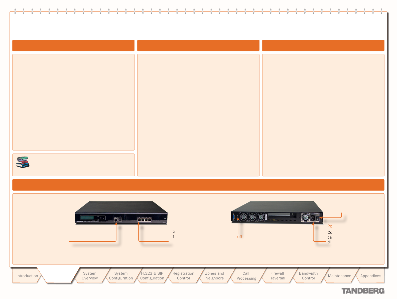
Connecting the Cables
General Installation Precautions
The socket outlet shall be installed near to the equipment
•
and shall be easily accessible.
Never install cables without first switching the power OFF.
•
Shielded serial cable
To control the VCS using a
direct connection to a PC,
connect the serial cable
between the VCS’s DATA port
and the COM port on a PC.
Getting
Introduction
D 14049.01
07.2007
Getting
Star ted
Star ted
System
Overview
System
Configuration
H.323 & SIP
Configuration
Ethernet cable.
To use the VCS over IP,
connect the ethernet cable
from the LAN1 port on the
VCS to your network. The
LAN2, 3 and 4 connectors
are not used and should be
left open.
Registration
Control
13
13
Zones and
Neighbors
Soft power button
Call
Processing
Firewall
Traversal
Bandwidth
Control
Power switch
Power cable
Connect the system power
cable to an electrical
distribution socket.
Maintenance
Appendices
Getting Started
TANDBERG VIDEO COMMUNICATION SERVER
ADMINISTRATOR GUIDE
Powering on the VCS
To start the VCS:
Ensure the power cable is connected.
1.
Ensure the LAN cable is connected to the
2.
LAN1 port.
Turn on the power switch on the back right
3.
of the unit (adjacent to the power cable).
Press the soft power button on the back
4.
left of the unit.
The system will star t up and the lights on the
front of the unit will flash.
Wait until:
5.
the green PWR LED on the front of the
•
unit is a steady green color
the red ALM LED on the front of the unit
•
has gone out.
the IP address is showing in the display
•
panel on the front of the unit.
Once this has happened, the system is ready
to configure.
The VCS requires some initial configuration
before it can be used. This must be done
using a PC connected to the DATA port or by
connecting to the system’s default IP address:
192.168.0.100.
The IP address, subnet mask and default
gateway must be configured before use.
Consult your network administrator for
information on which addresses to use. Note
that the VCS must use a static IP address.
To set the initial configuration via a PC
connected to the DATA port:
Connect the supplied serial cable from the
1.
DATA port on the VCS to the COM port on
a PC.
Star t a terminal emulator program on the
2.
PC and configure it to use the DATA port as
follows:
baud rate 115200
•
data bits: 8
•
parity: none
•
stop bits: 1
•
flow control: none.
•
Power on the unit (if it is not already on).
3.
The terminal emulator program will display
start up information.
After approximately 2 minutes you will get
the login prompt (if the unit is already on,
press Enter to get the login prompt):
tand berg login:
Enter the username admin and press Enter.
4.
You will get the password prompt:
Password:
Enter the default password of TANDBERG
5.
and press Enter.
You will get the install wizard prompt:
Run install wizard [n]:
Initial Configuration via Serial Cable
Type y and press Enter.
Follow the prompts given by the install
6.
wizard to specif y the following:
The password you want to use for your
a.
system. See Administrator Account
Password for details.
Whether you wish to use IPv4 or IPv6.
b.
See IP Protocol for details.
The IP address of the system.
c.
The IP subnet mask of the system.
d.
The IP default gateway of the system.
e.
The ethernet speed.
f.
Whether you want to use SSH to
g.
administer the system.
Whether you want to use Telnet to
h.
administer the system.
Once the wizard is f inished you will be
8.
prompted to log in again.
Login with the username admin and your
new password.
You will again get the install wizard prompt;
9.
this time select n and press Enter in order
to skip the wizard.
A welcome message similar to the following
will appear:
Welcome to
TANDBERG Video Com munication
Server Release X1.0
SW Release Date: 2007-07-20
OK
You must now reboot the system in order
10.
for the new settings take effect. To do this,
type the command:
xCom mand boot
Once it has rebooted, the VCS is ready to use.
You can continue to use the serial connection,
or you can connect to the system remotely over
IP using either or both:
the web interface via HT TPS
•
a command line inter face via SSH or Telnet.
•
We recommend that you now configure the
following:
The system name of the VCS. This is used
•
by the TANDBERG Management Suite (TMS)
to identify the system. See About the
System Name for more information.
Automatic discovery. If you have multiple
•
VCSs in the same network you may want
to disable automatic discovery on some
of them. See Auto Discover for more
information.
The DNS server address (if URI dialing
•
or FQDNs are to be used). See DNS
configuration for more information.
Introduction
D 14049.01
07.2007
Getting
Getting
Star ted
Star ted
System
Overview
System
Configuration
H.323 & SIP
Configuration
Registration
Control
14
14
Zones and
Neighbors
Call
Processing
Firewall
Traversal
Bandwidth
Control
Maintenance
Appendices
Getting Started
!
!
TANDBERG VIDEO COMMUNICATION SERVER
ADMINISTRATOR GUIDE
System Administrator Access
About Administrator Access
While it is possible to administer the TANDBERG VCS via a PC
connected directly to the unit via a serial cable, you may wish to
access the system remotely over IP.
You can do this using either or both:
the web interface via HT TPS
•
a command line inter face via SSH or Telnet.
•
By default, access via HT TPS and SSH is enabled; access via
Telnet is disabled.
You can also enable access via HTTP. However, this mode
works by redirecting HTTP calls to the HTTPS por t, so HT TPS
must also be enabled for access via HTTP to function.
TMS accesses the VCS via the web server. If HTTPS
mode is turned off, TMS will not be able to access it.
Configuring Administrator Access
To configure the ways in which your system is accessed:
System Configuration > System.
•
You will be taken to the System Administration page.
In the Admin Access section, select Off or On from the drop down boxes for each service.
xConfiguration Administration
•
You must restart the system for changes to take effect.
Administrator Account Password
All administration requires you to log in to the administration
account with the username admin (all lower case) and a
password.
Both the username and password are case- sensitive.
Default Administrator Password
The default password is TANDBERG (all upper case). You
should change this as soon as possible. Choose a strong
password, particularly if administration over IP is enabled.
Changing the Administrator Password
To change the administrator password:
Maintenance > Passwords.
•
You will be taken to the Passwords page.
In the Administrator Password section, enter and then retype
the new password.
xConfiguration SystemUnit Password
•
To set an empty password t ype:
xConfiguration SystemUnit Password: “”
Resetting the Administrator Password
If you forget your password, it is possible to set a new password
using the following procedure:
Reboot the VCS.
1.
Connect to the VCS using the serial cable.
2.
Login with the username pwrec. No password is required.
3.
You will be prompted for a new password.
Session Timeout
By default, Administrator sessions do not time out – they
remain active until you logout.
However, you can set the system to timeout an Administrator
session after a set number of minutes of inactivity. The timeout
period will apply to Administrator sessions using both the Web
Interface and the Command Line Interface.
To set the timeout period:
System Configuration > System.
•
You will be taken to the System Administration page.
In the Admin Access section, in the Session time out
(minutes) box, enter the number of minutes of inactivit y after
which an administrator session should time out.
xConfiguration Administration TimeOut
•
Values must be between 0 and 10,000. A value of 0 means
that Administrator sessions will never time out.
You must restart the system for changes to take effect.
Root Account
The VCS provides a root account with the same password as
the Admin account. This account should not be used in normal
operation, and in particular system configuration should not be
conducted using this account. Use the admin account instead.
Security Considerations
To securely manage the VCS you should disable Telnet, using
the encrypted HTTPS and SSH protocols instead.
For fur ther security, disable HTTPS and SSH as well and use
the serial port to manage the system.
System
Overview
D 14049.01
07.2007
Introduction
Getting
Getting
Star ted
Star ted
System
Configuration
The pwrec account is only active for one minute
following a restar t. Beyond that time you will have to
restar t the system again to change the password.
Because access to the serial port allows the password
to be reset, it is recommended that you install the VCS
in a physically secure environment.
H.323 & SIP
Configuration
Registration
Control
15
15
Zones and
Neighbors
Call
Processing
Firewall
Traversal
Bandwidth
Control
Maintenance
Appendices
Getting Started
TANDBERG VIDEO COMMUNICATION SERVER
ADMINISTRATOR GUIDE
System Administrator Access
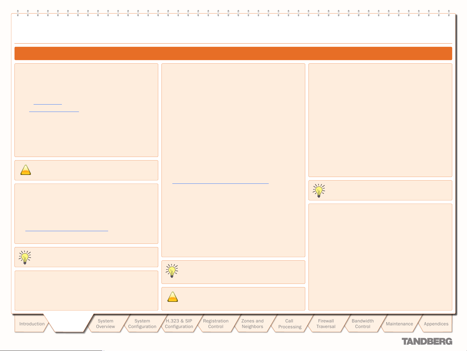
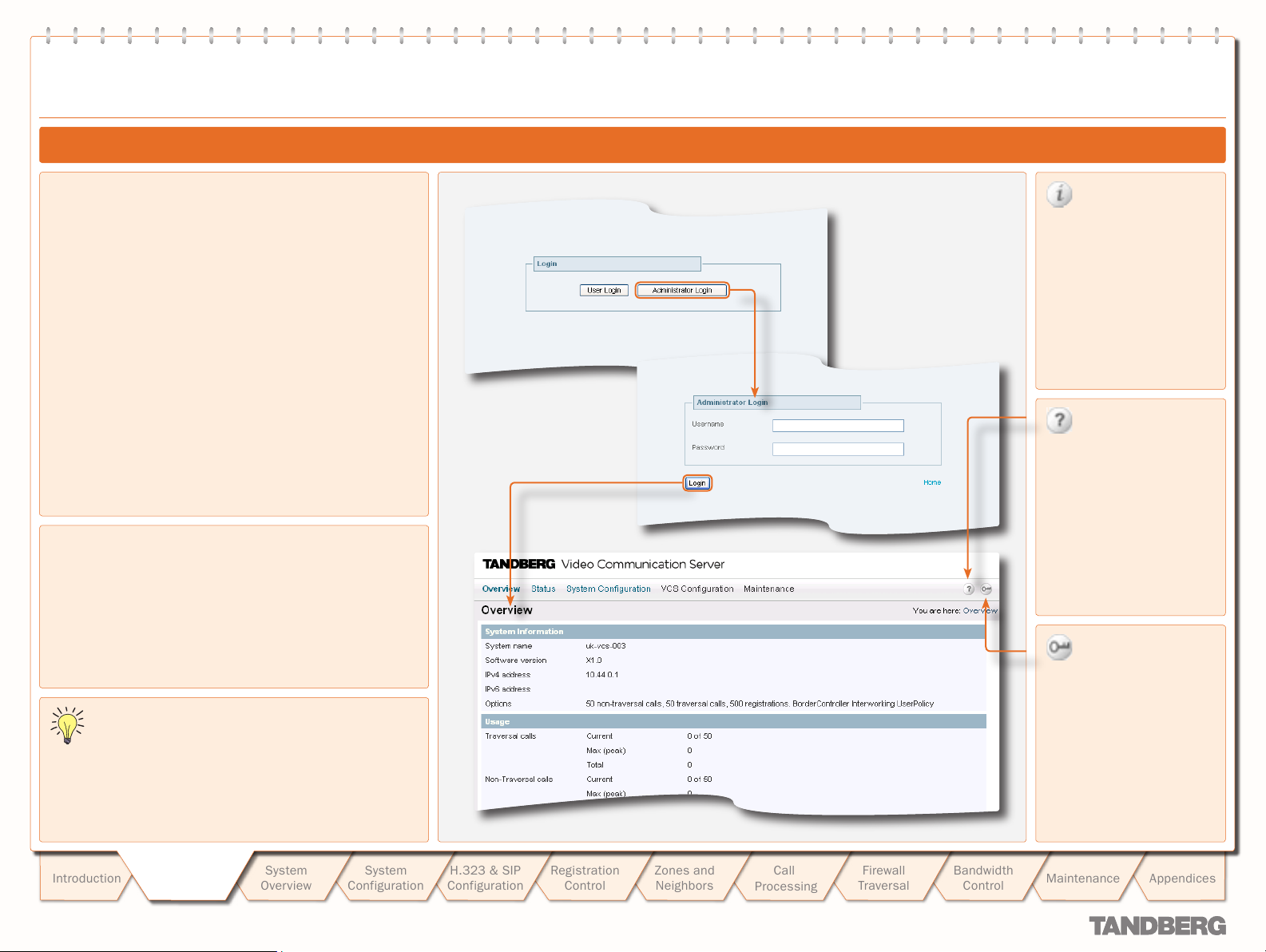
Using the Web Interface
To use the web interface:
Open a browser window and in the address line type either:
1.
the IP address of the system
•
the FQDN of the system.
•
Select Administrator Login.
2.
Enter the Username admin and your system password and
3.
select Login.
You will be presented with the Over view page.
Supported Browsers
The VCS web interface is designed for use with Internet
Explorer (6 and up) or Firefox (1.5 and up). It may work with
Opera and Safari, but you may encounter unexpected behavior.
Javascript must be enabled to use the VCS web inter face.
Information
This icon appears to the
right of most input fields in
the web interface.
Clicking on this icon will
activate a pop -up box which
gives you information about
that par ticular field.
View manual
This icon appears on the top
right corner of every screen.
Clicking on this icon will
take you directly to the
latest version of the VCS
Administrator Guide on the
TANDBERG website.
In this Administrator Guide, instructions for performing a
task via the web interface are shown in the format:
Menu option1 > Menu option2
•
followed by the Name of the page that you will be taken to
in order to perform the task. In most cases the page will
be shown adjacent with callouts describing each of the
configurable options.
Introduction
D 14049.01
07.2007
Getting
Getting
Star ted
Star ted
System
Overview
Configuration
System
H.323 & SIP
Configuration
Registration
Control
16
16
Zones and
Neighbors
Call
Processing
Firewall
Traversal
Bandwidth
Control
Log out
This icon appears on the top
right corner of every page.
Clicking on this icon will end
your Administrator session.
You will be taken to the
Administrator Login page.
Maintenance
Appendices
Getting Started
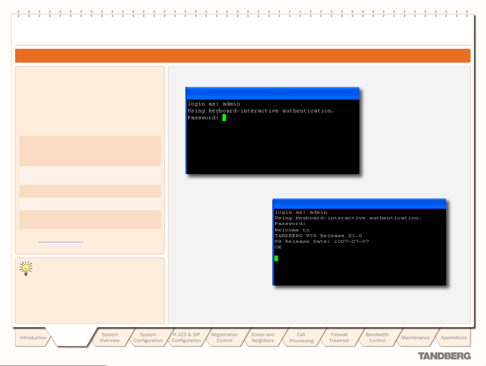
Using the Command Line Interface (CLI)
The command line interface is available over SSH, Telnet and
through the serial por t.
To use the command line interface:
Star t a SSH or Telnet session.
1.
Enter the IP address or FQDN of the VCS.
2.
Login with a username of admin and your system password.
3.
Commands are divided into different groups according to their
function:
xStatus
xConfiguration
xCom mand
xHistory
xFeedback
These commands return information
about the current status of the system.
Information such as current calls and
registrations is available through this
command group.
These commands allow you to add and
edit single items of data such as IP
address and zones.
These commands allow you to add and
configure items and obtain information.
These commands provide historical
information about calls and registrations.
These commands provide information
about events as they happen, such as
calls and registrations.
TANDBERG VIDEO COMMUNICATION SERVER
ADMINISTRATOR GUIDE
System Administrator Access
See the Command Reference Appendix for a full description of
commands available on the VCS.
In this Administrator Guide, instructions for performing a
task using the command line interface are shown in the
format:
xConfiguration Com mandName
•
Typing the given command into the CLI will return a full list of
options and parameters available for that command.
Typing a ? after the command will return information about the
purpose of that command or group of commands.
Introduction
D 14049.01
07.2007
Getting
Getting
Star ted
Star ted
System
Overview
System
Configuration
H.323 & SIP
Configuration
Registration
Control
17
17
Zones and
Neighbors
Call
Processing
Firewall
Traversal
Bandwidth
Control
Maintenance
Appendices
Text goes here
Viewing System Overview
TANDBERG VIDEO COMMUNICATION SERVER
TANDBERG VIDEO COMMUNICATION SERVER
ADMINISTRATOR GUIDE
ADMINISTRATOR GUIDE
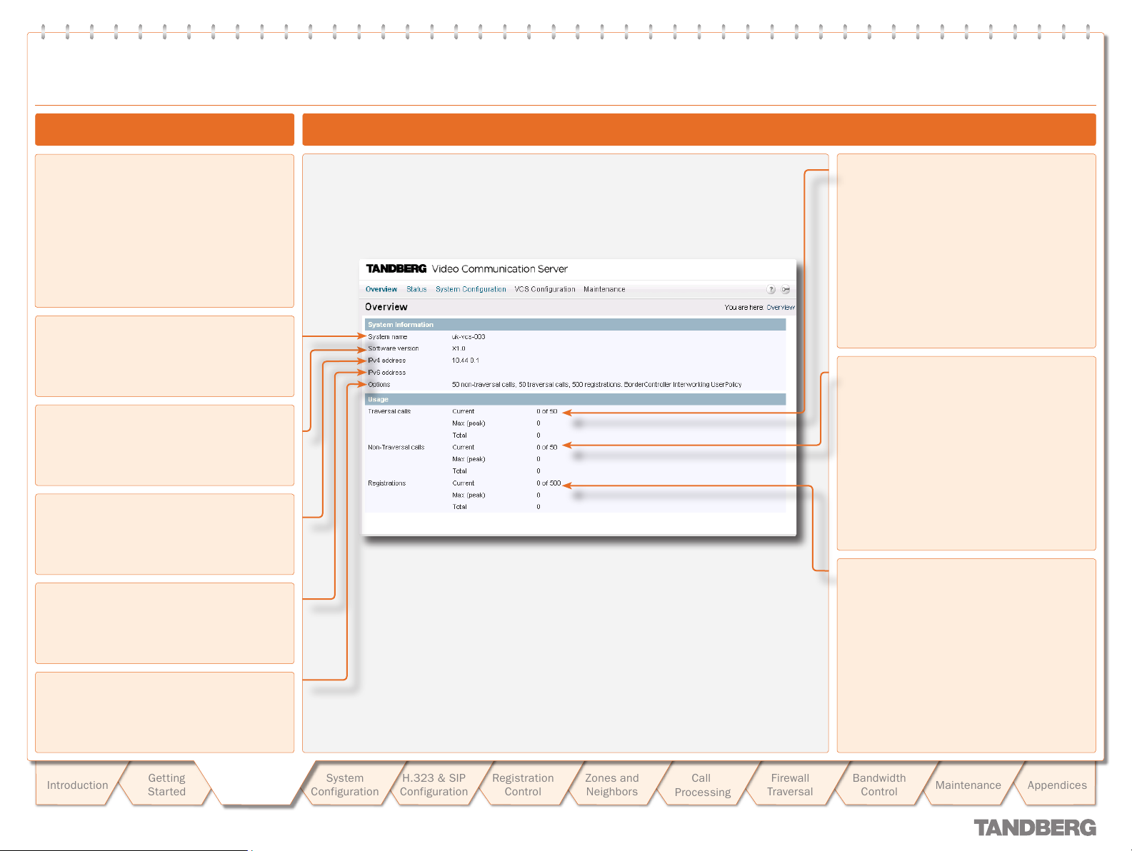
Viewing the Overview Page
The Overview page summarizes the current
configuration and status of your system.
The Overview page opens automatically when
you first log on to the web inter face.
You can also access it at any time by clicking
on the Overview link at the top left of the
page.
System name
This shows the name that has been assigned
to the VCS.
Software version
This shows the version of software that is
currently installed on the VCS.
IPv4 address
This shows the VCS’s IPv4 address.
Understanding the Overview Page
Traversal calls
Current: The number of traversal calls going
through the VCS at this moment.
Max (peak): The highest number of
concurrent traversal calls handled by the VCS
since it was last restarted.
Total: The total number of traversal calls
handled by the VCS since it was last
restar ted.
Non-traversal calls
Current: The number of non-traversal calls
going through the VCS at this moment.
Max (peak): The highest number of concurrent
non-traversal calls handled by the VCS since it
was last restarted.
Total: The total number of non-traversal
calls handled by the VCS since it was last
restar ted.
IPv6 address
This shows the VCS’s IPv6 address.
Options
This shows all the additional options that are
currently installed on the VCS.
System
Introduction
D 14049.01
07.2007
Getting
Star ted
System
Overview
Overview
System
Configuration
H.323 & SIP
Configuration
Registration
Control
18
Zones and
Neighbors
Call
Processing
Firewall
Traversal
Registrations
Current: The number of endpoints registered
to the VCS at this moment.
Max (peak): The highest number of endpoints
concurrently registered to the VCS since it
was last restarted.
Total: The total number of registrations on the
VCS since it was last restarted.
Bandwidth
Control
Maintenance
Appendices
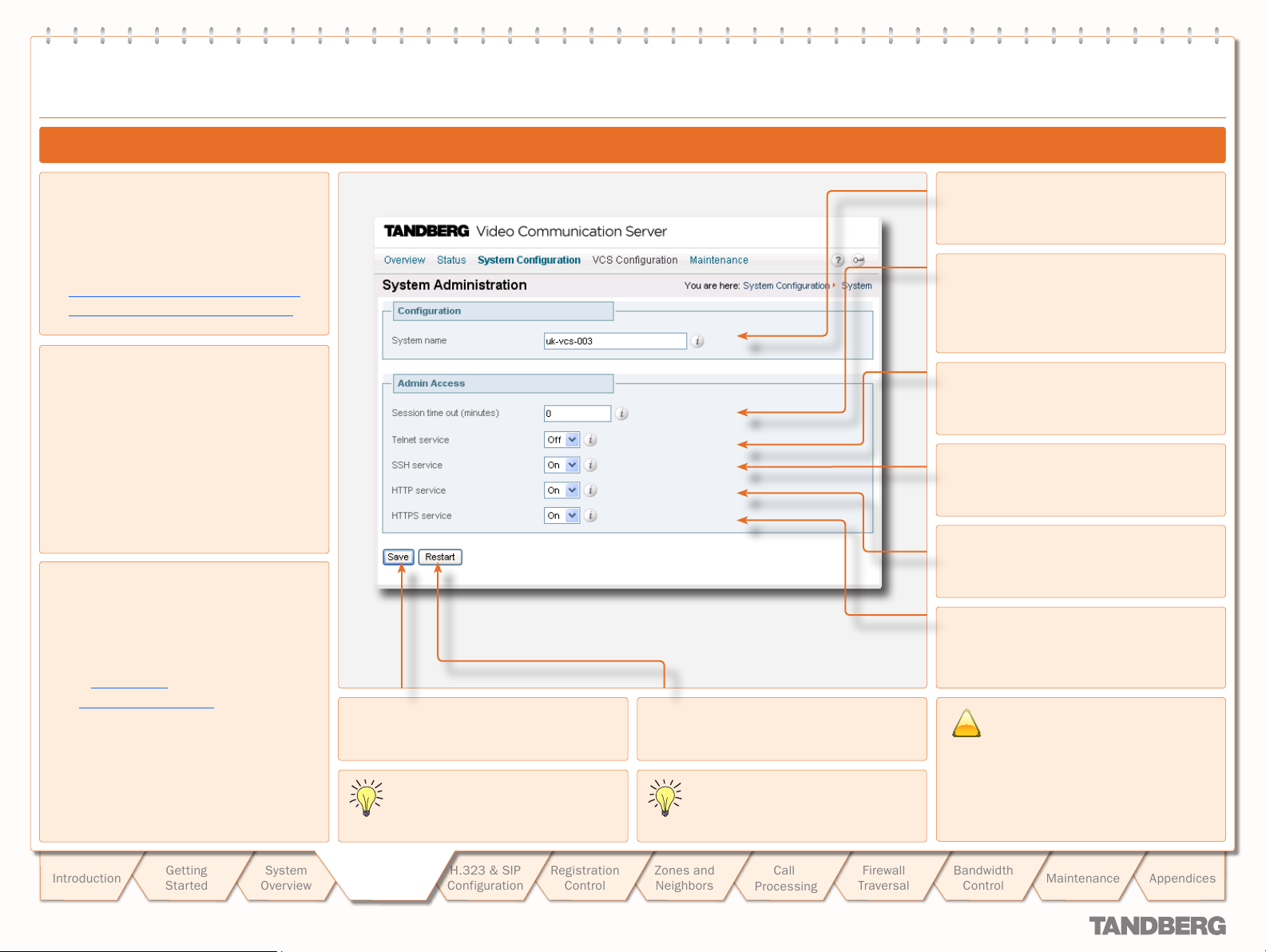
text
!
System Conguration
System Administration Configuration
TANDBERG VIDEO COMMUNICATION SERVER
TANDBERG VIDEO COMMUNICATION SERVER
ADMINISTRATOR GUIDE
ADMINISTRATOR GUIDE
Configuring System Settings
To configure the VCS’s system administration
settings:
System Configuration > System.
•
You will be taken to the System
Administration page.
xConfiguration SystemUnit Name
•
xConfiguration Administration
•
About the System Name
The system name is used to identify the VCS,
for example in TMS.
It appears in various places in the web
interface, and in the display on the front panel
of the unit, so that you can identify it when it
is in a rack with other boxes. If no name is
specif ied, these fields/display will be blank.
We recommend that you give the VCS a name
that allows you to easily and uniquely identify
it.
About Admin Access settings
While it is possible to administer the
TANDBERG VCS via a PC connected directly
to the unit via a serial cable, you may wish to
access the system remotely over IP.
You can do this using either or both:
the web interface via HT TPS
•
a command line inter face via SSH or
•
Telnet.
By default, access via HT TPS and SSH is
enabled; access via Telnet is disabled.
You can also enable access via HTTP.
However, this mode works by redirecting HT TP
calls to the HTTPS port, so HTTPS must also
be enabled for access via HTTP to function.
Save
Click here to save your changes.
You must save your changes and
restar t the system for changes to take
effect.
Restar t
Click here to restart the system.
TMS accesses the VCS via the web
server. If HTTPS mode is turned off,
TMS will not be able to access it.
System name
Defines the name of the VCS. Choose a name
that uniquely identifies the system.
Session time out (minutes)
Sets the number of minutes that an
administration session (HTTPS, Telnet or SSH)
may be inactive before the session is timed
out. A value of 0 turns session time outs of f.
Telnet service
Determines whether the VCS can be accessed
via Telnet.
SSH service
Determines whether the VCS can be accessed
via SSH and SCP.
HTTP service
Determines whether HTTP calls will be
redirected to the HTTPS port.
HTTPS service
Determines whether the VCS can be accessed
via the web server. This must be On to enable
both web interface and TMS access.
By default, access via HT TPS and SSH
is enabled; access via Telnet is
disabled. To securely manage the VCS
you should disable Telnet, using the encrypted
HTTPS and SSH protocols instead. For further
security, disable HTTPS and SSH as well and
use the serial por t to manage the system.
D 14049.01
07.2007
Introduction
Getting
Star ted
System
Overview
System
System
Configuration
Configuration
H.323 & SIP
Configuration
Registration
Control
19
Zones and
Neighbors
Call
Processing
Firewall
Traversal
Bandwidth
Control
Maintenance
Appendices
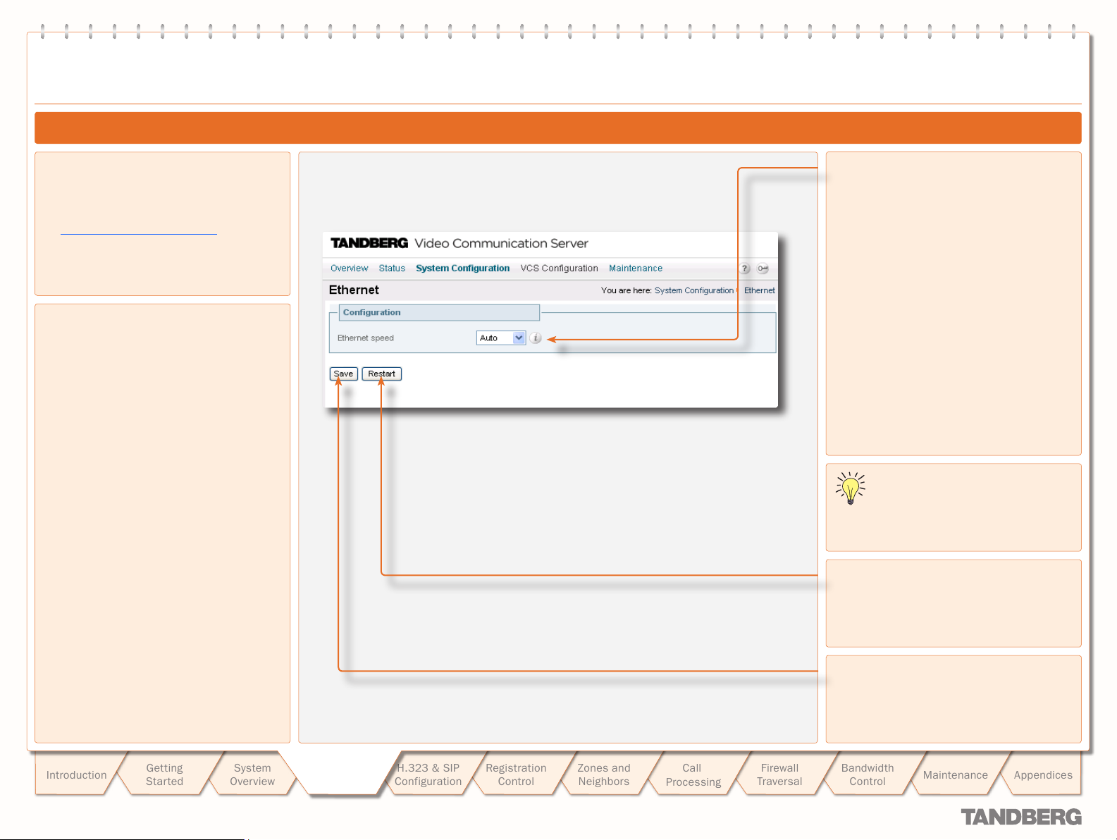
text
System Conguration
Ethernet Configuration
TANDBERG VIDEO COMMUNICATION SERVER
TANDBERG VIDEO COMMUNICATION SERVER
ADMINISTRATOR GUIDE
ADMINISTRATOR GUIDE
Configuring Ethernet Settings
To configure the VCS’s Ethernet settings:
System Configuration >Ethernet.
•
You will be taken to the Ethernet page.
xConfiguration Ethernet
•
About Ethernet Speed
The Ethernet speed setting determines the
speed of the connection between the VCS
and the ethernet switch. It must be set to the
same value on both systems.
The default is Auto. We recommend that you
do not change the default value unless the
switch to which you are connecting is unable
to auto-negotiate.
Ethernet speed
Sets the speed of the connection between the
VCS and the ethernet switch.
You must save your changes and
restar t the system for changes to take
effect.
Restar t
Click here to restart the system.
Introduction
D 14049.01
07.2007
Getting
Star ted
System
Overview
System
System
Configuration
Configuration
H.323 & SIP
Configuration
Registration
Control
20
Zones and
Neighbors
Call
Processing
Firewall
Traversal
Save
Click here to save your changes.
Bandwidth
Control
Maintenance
Appendices
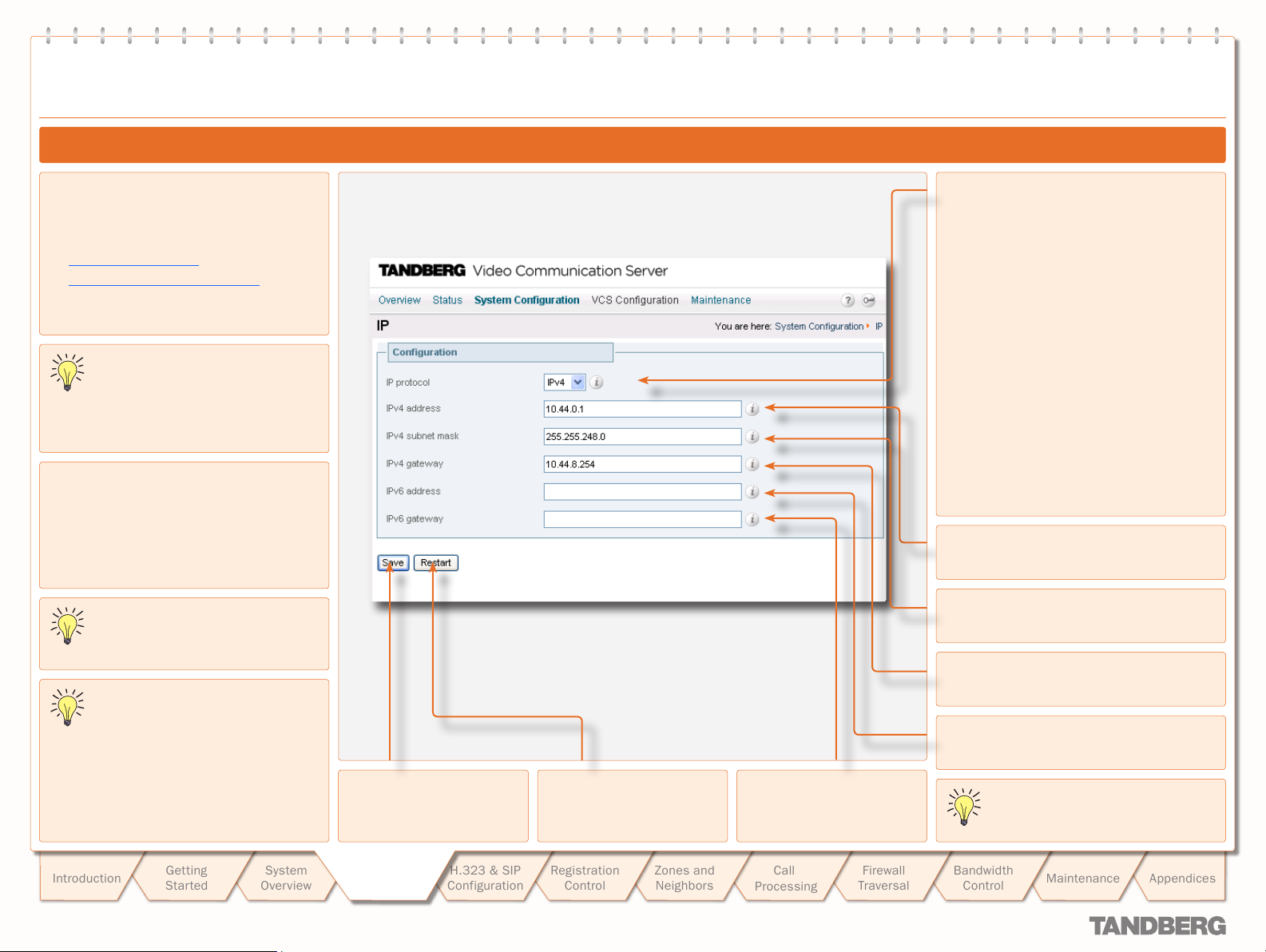
text
System Conguration
IP Configuration
TANDBERG VIDEO COMMUNICATION SERVER
TANDBERG VIDEO COMMUNICATION SERVER
ADMINISTRATOR GUIDE
ADMINISTRATOR GUIDE
Configuring IP Settings
To configure the VCS’s IP settings:
System Configuration > IP.
•
You will be taken to the IP page.
xConfiguration IP
•
xConfiguration IPProtocol
•
The VCS is shipped with a default
IP address of 192.168.0.100. This
allows you to connect the VCS to your
network and access it via the default address
so that you can configure it remotely.
About IPv4 to IPv6 Gatewaying
The VCS can act as a gateway between IPv4
and IPv6 calls.
To configure the VCS to act as a gateway
between the two protocols, select an
IP Protocol of Both.
Calls for which the VCS is acting as an
IPv4 to IPv6 gateway count as traversal
calls for the purposes of licensing.
Some endpoints suppor t both IPv4 and
IPv6, however an endpoint can use
only one protocol when registering with
the VCS. Which protocol it uses will be
determined by the format used to specify the
IP address of the VCS on the endpoint. Once
the endpoint has registered using one
protocol, calls to it from an endpoint using the
other protocol will be gatewayed by the VCS.
Save
Click here to save your
changes.
Restar t
Click here to restart the
system.
IPv6 gateway
Specifies the IPv6 gateway
of the system.
IP protocol
You can configure the VCS to use IPv4, IPv6 or
Both protocols. The default is Both.
IPv4: The VCS will only accept registrations
from endpoints using an IPv4 address, and
will only take calls between two endpoints
communicating via IPv4. It will communicate
with other systems via IPv4 only.
IPv6: The VCS will only accept registrations
from endpoints using an IPv6 address, and
will only take calls between two endpoints
communicating via IPv6. It will communicate
with other systems via IPv6 only.
Both: The VCS will accept registrations
from endpoints using either an IPv4 or IPv6
address, and will take calls using either
protocol. If a call is between an IPv4 -only and
an IPv6- only endpoint, the VCS will act as an
IPv4 to IPv6 gateway. It can communicate with
other systems via either protocol.
IPv4 address
Specifies the IPv4 address of the system.
IPv4 subnet mask
Specifies the IPv4 subnet mask of the system.
IPv4 gateway
Specifies the IPv4 gateway of the system.
IPv6 address
Specifies the IPv6 address of the system.
You must save your changes and
restar t the system for changes to take
effect.
Introduction
D 14049.01
07.2007
Getting
Star ted
System
Overview
System
System
Configuration
Configuration
H.323 & SIP
Configuration
Registration
Control
21
Zones and
Neighbors
Call
Processing
Firewall
Traversal
Bandwidth
Control
Maintenance
Appendices
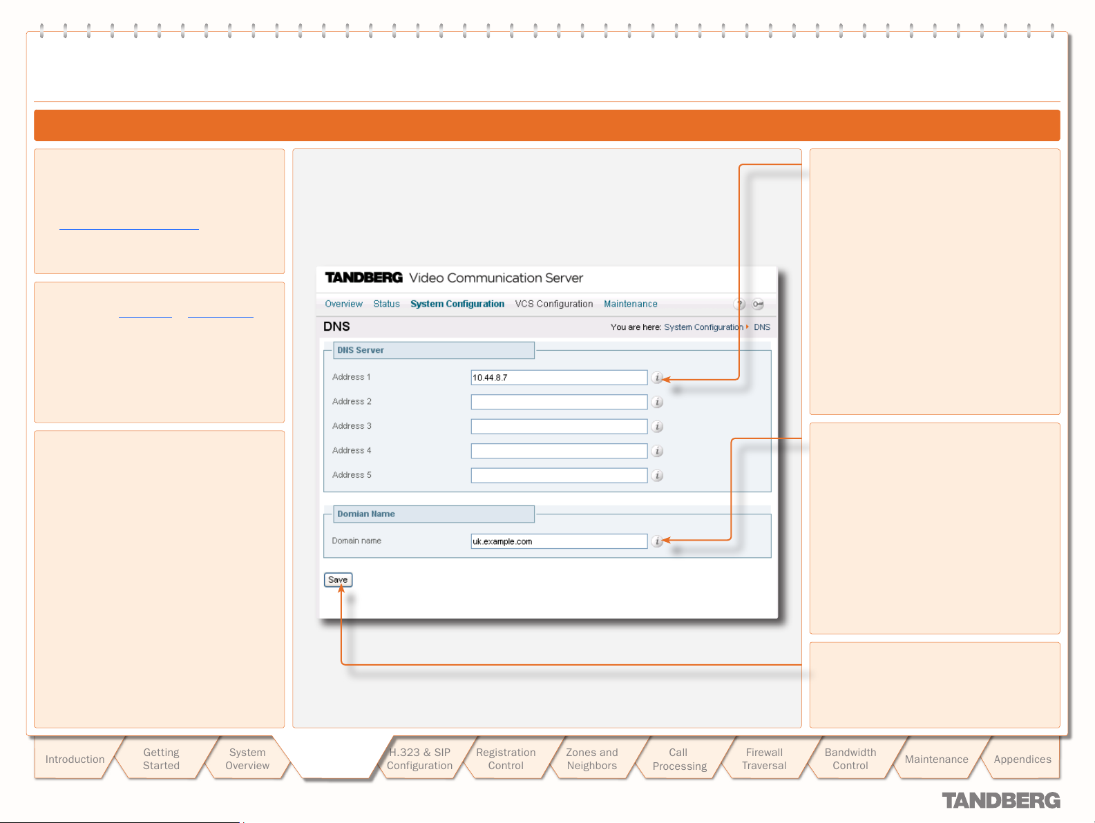
text
System Conguration
DNS Configuration
TANDBERG VIDEO COMMUNICATION SERVER
TANDBERG VIDEO COMMUNICATION SERVER
ADMINISTRATOR GUIDE
ADMINISTRATOR GUIDE
Configuring DNS Settings
To configure the VCS’s DNS settings:
System Configuration > DNS.
•
You will be taken to the DNS page.
xConfiguration IP DNS
•
About DNS Servers
In order to use URI dialing or ENUM dialing,
you must specify a DNS ser ver to be queried
for address resolution. You can specify up to
5 DNS ser vers. Normally only the f irst DNS
server will be queried, but if it fails to respond,
all DNS ser vers will be queried.
About the DNS Domain Name
The DNS Domain Name is used when
attempting to resolve ser ver addresses
configured on the VCS that are not fully
qualified. It applies only to the following:
LDAP ser ver
•
NTP ser ver
•
External Manager ser ver.
•
The DNS Domain Name is appended to the
server address before a query to the DNS
server is executed. Note however that DNS
will also be queried for the ser ver address as
configured, without the DNS Domain Name
appended. For this reason we recommend
that all server addresses use a FQDN.
The DNS Domain name plays no part in URI
dialing.
Address 1 to Address 5
Sets the IP address of a DNS server to be
queried when resolving domain names.
Domain name
Specifies the name to be appended to the
host name before a query to the DNS server
is executed.
Save
Click here to save your changes.
Introduction
D 14049.01
07.2007
Getting
Star ted
System
Overview
System
System
Configuration
Configuration
H.323 & SIP
Configuration
Registration
Control
22
Zones and
Neighbors
Call
Processing
Firewall
Traversal
Bandwidth
Control
Maintenance
Appendices
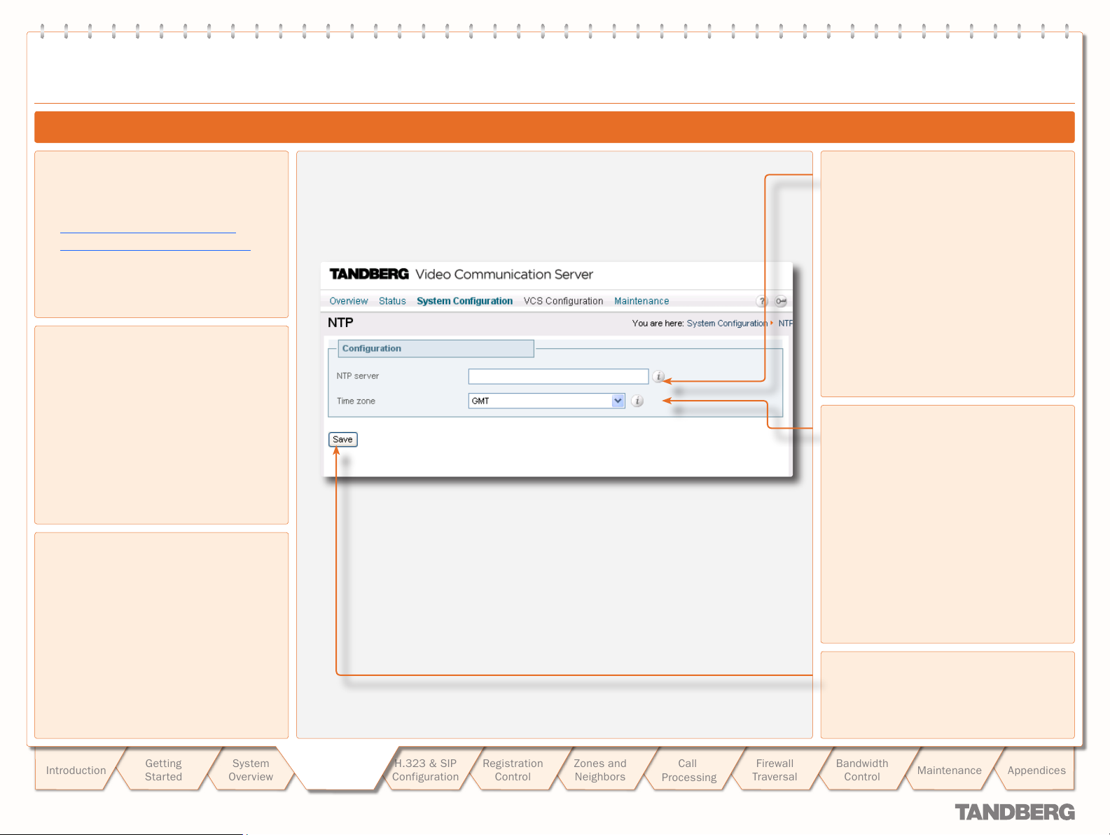
text
System Conguration
NTP Configuration
TANDBERG VIDEO COMMUNICATION SERVER
TANDBERG VIDEO COMMUNICATION SERVER
ADMINISTRATOR GUIDE
ADMINISTRATOR GUIDE
Configuring NTP Settings
To configure the VCS’s NTP settings:
System Configuration > NTP
•
You will be taken to the NTP page.
xConfiguration NTP Address
•
xConfiguration TimeZone Name
•
About the NTP Server
Accurate timestamps play an impor tant part in
authentication, helping to guard against replay
attacks. For this reason, we recommend that
you use an NTP server to synchronize the
system time.
Setting the Time Zone
All events are recorded using the local date
and time as well as UTC time. The local time
is determined by the Time Zone set on the
VCS.
NTP ser ver
Sets the IP address or FQDN of the NTP server
to be used when synchronizing system time.
Time zone
Sets the local time zone of the VCS.
Introduction
D 14049.01
07.2007
Getting
Star ted
System
Overview
System
System
Configuration
Configuration
H.323 & SIP
Configuration
Registration
Control
23
Zones and
Neighbors
Call
Processing
Firewall
Traversal
Save
Click here to save your changes.
Bandwidth
Control
Maintenance
Appendices
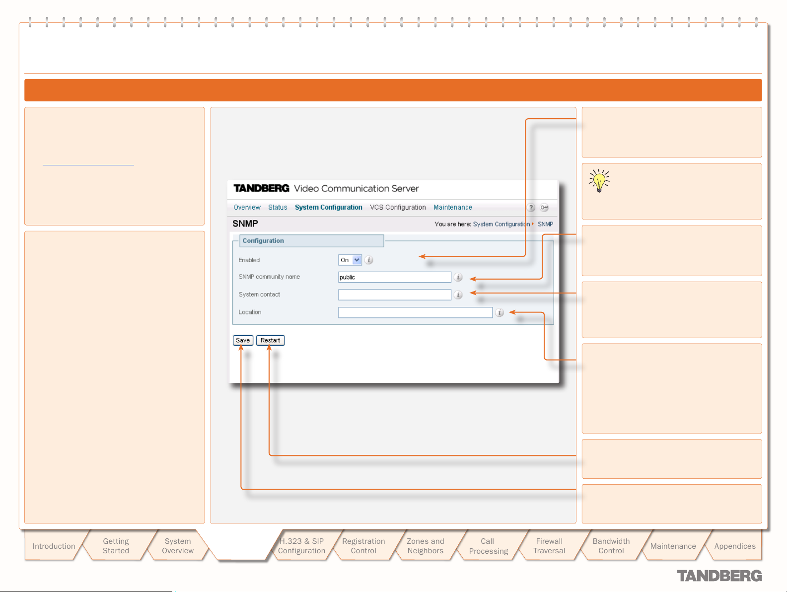
text
System Conguration
SNMP Configuration
TANDBERG VIDEO COMMUNICATION SERVER
TANDBERG VIDEO COMMUNICATION SERVER
ADMINISTRATOR GUIDE
ADMINISTRATOR GUIDE
Configuring SNMP Settings
To configure the VCS’s SNMP settings:
System Configuration > SNMP
•
You will be taken to the SNMP page.
xConfiguration SNMP
•
About SNMP Settings
The VCS of fers basic support for SNMP.
Tools such as TANDBERG Management Suite
(TMS) or HP OpenView may act as SNMP
network management systems (NMS). They
allow you to monitor your network devices,
including the VCS, for conditions that might
require administrative attention.
To allow the VCS to be monitored by a SNMP
NMS, you must enable SNMP on the VCS and
provide the name of the SNMP community
within which it resides. You may optionally
provide the name of a System contact and the
physical Location of the system for reference
by administrators when following up on
queries.
By default, SNMP is Enabled with a SNMP
community name of public.
Note: the VCS does not support SNMP traps,
therefore it cannot be managed via SNMP.
Enabled
Select On to enable SNMP suppor t.
You must save your changes and
restar t the system for any changes to
take effect.
SNMP community name
Sets the VCS’s SNMP community name.
System contact
Specifies the name of the person who can be
contacted regarding issues with the VCS.
Location
Specifies the physical location of the VCS.
Restar t
Click here to restart the system.
Introduction
D 14049.01
07.2007
Getting
Star ted
System
Overview
System
System
Configuration
Configuration
H.323 & SIP
Configuration
Registration
Control
24
Zones and
Neighbors
Call
Processing
Firewall
Traversal
Save
Click here to save your changes.
Bandwidth
Control
Maintenance
Appendices
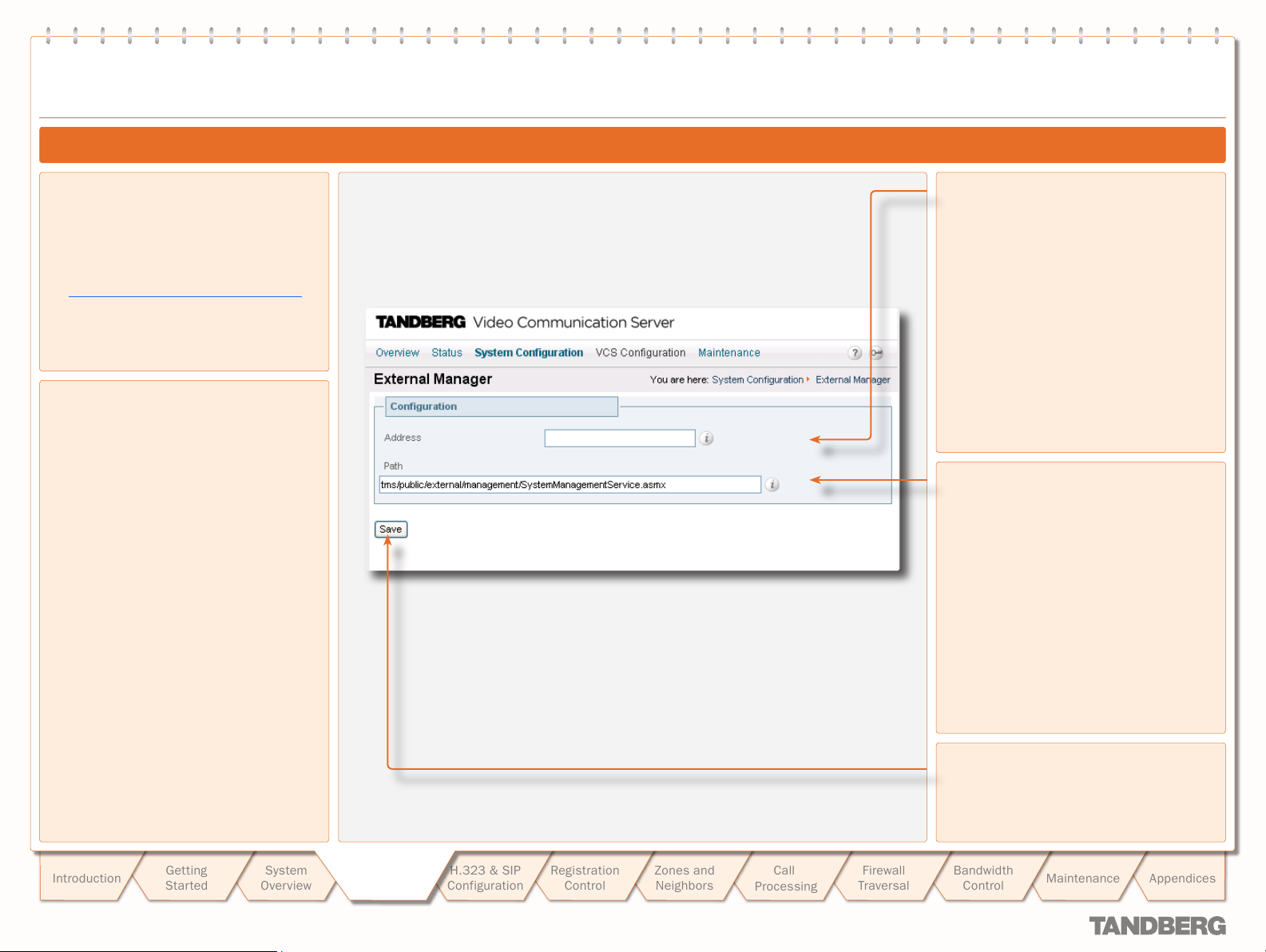
text
System Conguration
External Manager Configuration
TANDBERG VIDEO COMMUNICATION SERVER
TANDBERG VIDEO COMMUNICATION SERVER
ADMINISTRATOR GUIDE
ADMINISTRATOR GUIDE
Configuring External Manager Settings
To configure the VCS’s External Manager
settings:
System Configuration > External Manager.
•
You will be taken to the External Manager
page.
xConfiguration ExternalManager
•
About the External Manager
An External Manager is a remote system, such
as the TANDBERG Management Suite (TMS),
used to monitor events occurring on the VCS,
for example call attempts, connections and
disconnections.
The use of an External Manager is optional.
In order to use an Ex ternal Manager, you must
configure the VCS with the IP address or host
name and path of the External Manager to be
used.
If you are using TMS as your external
manager, use the default path of
tms/public/ external/management/
SystemManagementSer vice.asmx.
Address
Sets the IP address or FQDN of the External
Manager.
Path
Sets the path of the External Manager.
Introduction
D 14049.01
07.2007
Getting
Star ted
System
Overview
System
System
Configuration
Configuration
H.323 & SIP
Configuration
Registration
Control
25
Zones and
Neighbors
Call
Processing
Firewall
Traversal
Save
Click here to save your changes.
Bandwidth
Control
Maintenance
Appendices
text
System Conguration
Backing up Configuration Settings
You are recommended to maintain a backup of your VCS configuration. To do this:
1.
Use the command line interface to log on to the VCS.
Issue the command xConfiguration.
2.
Save the resulting output to a file, using cut-and-paste or some other means provided by your
3.
terminal emulator.
To restore your configuration:
Remove the *c from in front of each command.
1.
Paste this information back in to the command line interface.
2.
TANDBERG VIDEO COMMUNICATION SERVER
TANDBERG VIDEO COMMUNICATION SERVER
ADMINISTRATOR GUIDE
ADMINISTRATOR GUIDE
Introduction
D 14049.01
07.2007
Getting
Star ted
System
Overview
System
System
Configuration
Configuration
H.323 & SIP
Configuration
Registration
Control
26
Zones and
Neighbors
Call
Processing
Firewall
Traversal
Bandwidth
Control
Maintenance
Appendices
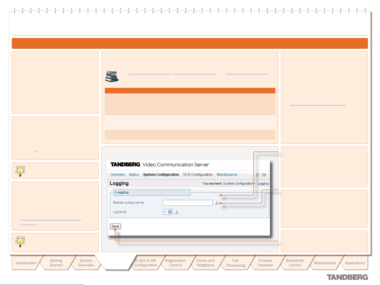
Logging
Logging
Logging Overview
TANDBERG VIDEO COMMUNICATION SERVER
TANDBERG VIDEO COMMUNICATION SERVER
ADMINISTRATOR GUIDE
ADMINISTRATOR GUIDE
About Logging
The VCS provides a logging facility for
troubleshooting and auditing purposes. The
event log contains information about such
things as calls, registrations, and messages
sent and received.
The VCS logging facilit y allows you to:
specif y the amount of information that is
•
logged by changing the event log level,
specif y an external server to which a copy
•
of the log is written.
About Remote Logging
The event log is stored locally on the VCS.
However, it is often convenient to collect
copies of all event logs from various systems
in a single location. A computer running
a BSD-style syslog server, as defined in
RFC 3164 [4] , may be used as the central log
server.
A VCS will not act as a central logging
server for other systems.
Enabling Remote Logging
To enable remote logging, you must configure
the VCS with the address of the central log
server. To do this:
System Configuration > Log ging.
•
You will be taken to the Logging page.
xConfiguration Log Ser ver
•
Address
About Event Log Levels
All events have an associated level in the range 1-3, with level 1 events considered the most
impor tant. The table below gives an over view of the levels assigned to different events.
See Events Logged at Level 1, Events Logged at Level 2 and Events Logged at Level 3 for
complete tables of the events logged at each level.
Level Assigned Events
Level 1
(User)
Level 2
(Protocol)
Level 3
(Protocol Verbose)
High-level events such as registration requests and call at tempts. Easily
human readable. For example:
call attempt/connected/disconnected
•
registration at tempt/accepted/rejected.
•
Logs of protocol messages sent and received (H.323, LDAP, etc.) excluding
noisy messages such as H.460.18 keepalives and H.245 video fastupdates.
Protocol keepalives are suppressed at Level 2. At log ging Level 3,
keepalives are also logged.
Setting the Event Log Level
You can control which events are logged by
the VCS by setting the log level. All events
with a level numerically equal to and lower
than the specified log ging level are recorded
in the event log.
To set the log level:
System Configuration > Log ging.
•
You will be taken to the Logging page.
xConfiguration Log Level
•
Remote syslog server
Enter the IP address or FQDN of the ser ver to
which the log will be written.
Log level
Select the level of logging you require.
The default is 1.
Events will be always logged locally
regardless of whether or not remote
logging has been enabled.
Introduction
D 14049.01
07.2007
Getting
Star ted
System
Overview
System
System
Configuration
Configuration
H.323 & SIP
Configuration
Registration
Control
27
Zones and
Neighbors
Call
Processing
Firewall
Traversal
Save
Click here to save your changes.
Bandwidth
Control
Maintenance
Appendices
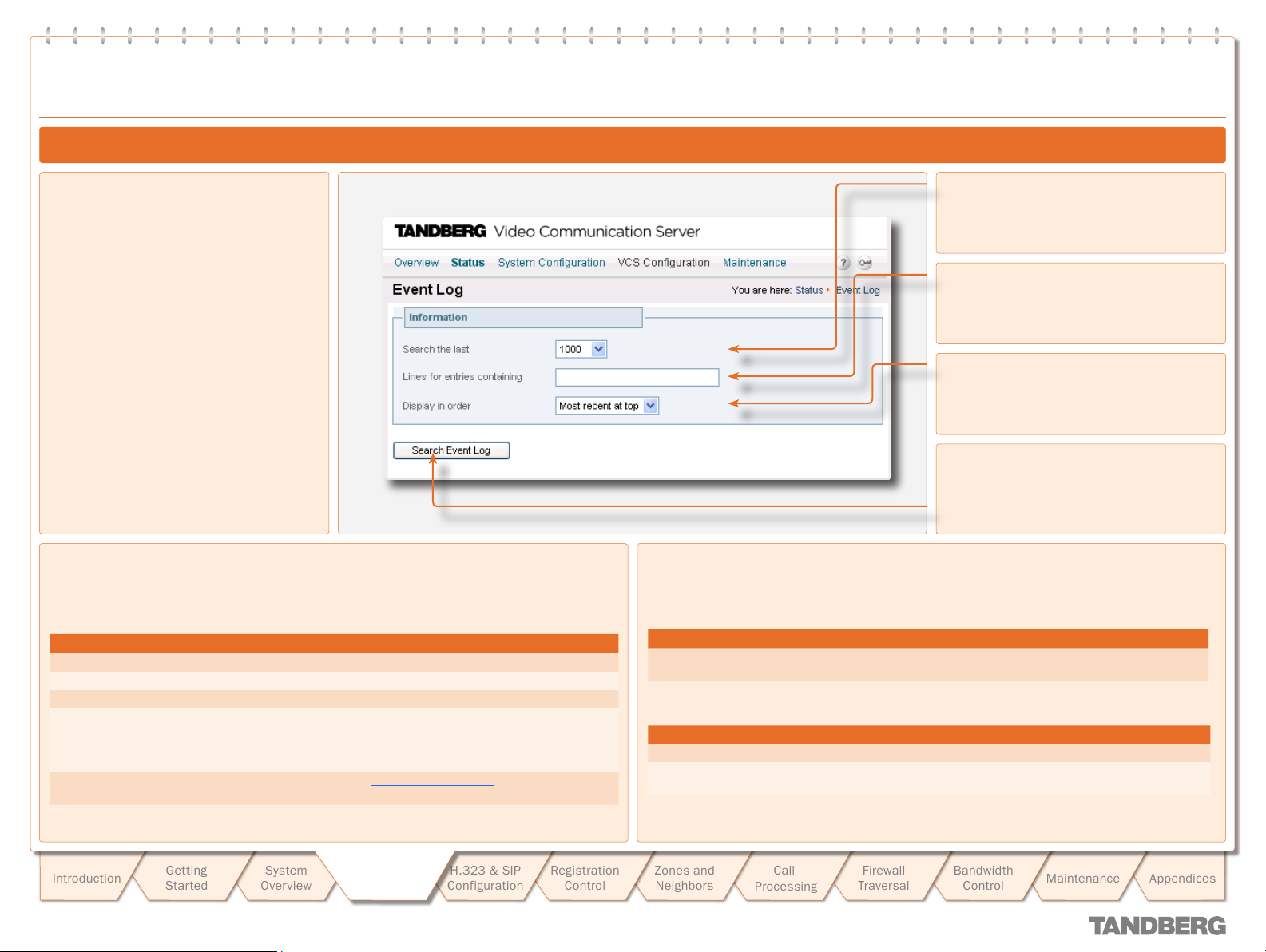
Logging
Logging
Event Log
TANDBERG VIDEO COMMUNICATION SERVER
TANDBERG VIDEO COMMUNICATION SERVER
ADMINISTRATOR GUIDE
ADMINISTRATOR GUIDE
Viewing the Event Log
To view the event log:
Status > Event Log.
•
You will be taken to the Event Log page,
where you can search and view the Event
Log.
eventlog
•
Event Log Format
The event log is displayed in an extension of the UNIX syslog format:
date time host _ name facility _ name <PID>: message _ details
where:
Field Description
date
time
host _ name
facility _ name
message _ details
the local date on which the message was logged
the local time at which the message was logged
the name of the system generating the log message
the name of the program generating the log message. This will be
tandberg for all messages originating from TANDBERG processes, but
will differ for messages from third party processes which are used in the
VCS product
the body of the message (see Message details field for fur ther
information)
Search the last
Select the number of events you wish to view
or search.
Lines for entries containing
If you wish to filter your search, enter the text
that you wish to search for here.
Display in order
Select whether you want the oldest or newest
items to appear at the top of the log.
Search Event Log
Click here once you have configured your
search options. The event log will be
displayed below the Information field.
Message Details Field
For all messages logged from the tandberg process the field is structured to allow easy parsing.
It consists of a number of human -readable name=value pairs, separated by a space.
The first field is always:
Field Example Description
Event
and the last fields of the message are always:
Field Example Description
Level
Time
Event=RegistrationReq uest
Level=1
Time=2006/20/01-14:02:17
The event which caused the log message to be
generated.
The level of the event being log ged.
The UTC date and time at which the event was
generated.
Introduction
D 14049.01
07.2007
Getting
Star ted
System
Overview
System
System
Configuration
Configuration
H.323 & SIP
Configuration
Registration
Control
28
Zones and
Neighbors
Call
Processing
Firewall
Traversal
Bandwidth
Control
Maintenance
Appendices
Logging
Logging
Event Description
Eventlog Cleared
Adm in Session Start
Adm in Session Finish
System Configuration Changed
Policy Change
Registration Requested
Registration Accepted
Registration Rejected
Registration Removed
Registration Refresh Rejected
Unregistration Requested
Unregistration Rejected
Call Answer Attempted
Call Attempted
Call Connected
Call Disconnected
Call Rejected
Call Bandwidth Changed
External Server Communication
Failure
System Start
An operator cleared the event log.
An administrator has logged onto the system.
An administrator has logged off the system.
An item of configuration on the system has changed.
The Detail event parameter contains the name of the changed configuration item and its new value.
A policy file has been updated.
A registration has been requested.
A registration request has been accepted.
A registration request has been rejected.
The Reason event parameter contains the H.225 cause code. Optionally, the Detail event parameter may contain a textual representation of the
H.225 additional cause code.
A registration has been removed by the VCS.
The Reason event parameter specifies the reason why the registration was removed. This is one of:
Authentication change
•
Conflicting zones
•
Operator forced removal
•
Operator forced removal (all registrations removed)
•
A request to refresh a registration has been rejected.
An unregistration request has been received.
An unregistration request has been rejected.
An attempt to answer a call has been made.
A call has been attempted.
A call has been connected.
A call has been disconnected.
A call has been rejected.
The Reason event parameter contains a tex tual representation of the H.225 additional cause code.
The bandwidth of a call has changed.
Communication with an external server failed unexpectedly. The event detail data should differentiate between ‘no response’ and ‘request rejected’.
Servers concerned are:
DNS
•
LDAP ser vers
•
Neighbor Gatekeeper
•
NTP ser vers
•
The operating system has started.
Events Logged at Level 1
TANDBERG VIDEO COMMUNICATION SERVER
TANDBERG VIDEO COMMUNICATION SERVER
ADMINISTRATOR GUIDE
ADMINISTRATOR GUIDE
Introduction
D 14049.01
07.2007
Getting
Star ted
System
Overview
System
System
Configuration
Configuration
H.323 & SIP
Configuration
Registration
Control
29
Zones and
Neighbors
Call
Processing
Firewall
Traversal
Bandwidth
Control
Maintenance
Appendices
Logging
Logging
Event Description
System Shutdown
Application Start
Application Failed
License Limit Reached
Decode Error
TLS Negotiation Error
The operating system was shutdown.
The VCS has started.
Further detail may be provided in the event data Detail field.
The VCS application is out of service due to an unexpected failure.
Licensing limits for a given feature have been reached.
The event detail field specifies the facility/limits concerned. Possible values for the detail field are:
Non Traversal Call Limit Reached
•
Traversal Call Limit Reached
•
A syntax error was encountered when decoding a SIP message.
Transport Layer Security (TLS) connection failed to negotiate.
Event Description
Message Received
Message Sent
Registration Refresh Request
Registration Refresh Accepted
Request Received
Request Sent
Response Received
Response Sent
(H.323) An incoming message has been received.
(H.323) An out going message has been sent.
A request to refresh a registration has been received.
A request to refresh a registration has been accepted.
A SIP request has been received.
A SIP request has been sent.
A SIP response has been received.
A SIP response has been sent.
Events Logged at Level 1 cont...
Events Logged at Level 2
TANDBERG VIDEO COMMUNICATION SERVER
TANDBERG VIDEO COMMUNICATION SERVER
ADMINISTRATOR GUIDE
ADMINISTRATOR GUIDE
Event Description
Message Received
Message Sent
Introduction
D 14049.01
07.2007
Getting
Star ted
System
Overview
(SIP) An incoming message has been received.
(SIP) An outgoing message has been sent.
Configuration
Configuration
System
System
H.323 & SIP
Configuration
Events Logged at Level 3
Registration
Control
Zones and
Neighbors
30
Call
Processing
Firewall
Traversal
Bandwidth
Control
Maintenance
Appendices

Logging
Logging
Field Description
Protocol
Reason
Service
Message Type
ResponseCode
Src-ip
Dst-ip
Dst-port
Src-port
Src-Alias
Dst-Alias
Auth
Method
Contact
AOR
Specifies which protocol was used for the communication.
Valid values are:
TCP
•
UDP
•
TLS
•
Textual string containing any reason information associated with an event.
Specifies which protocol was used for the communication.
A service entry is one of:
H.323
•
SIP
•
H.225
•
H.245
•
NTP
•
DNS
•
LDAP
•
Q.931
•
Neighbor Gatekeeper
•
Specifies the type of the message.
SIP response code.
Specifies the source IP address (the IP address of the device attempting to establish communications).
The source IP is recorded in the dotted decimal format: (number).(number).(number).(number) or the IPv6 colon separated format.
Specifies the destination IP address (the IP address of the destination for a communication attempt).
The destination IP is recorded in the same format as Src-ip.
Specifies the destination por t: the IP port of the destination for a communication attempt.
Specifies the source port: the IP por t of the device attempting to establish communications.
If present, the first H.323 Alias associated with the originator of the message
If present, the first E.164 Alias associated with the originator of the message
If present, the first H.323 Alias associated with the recipient of the message
If present, the first E.164 Alias associated with the recipient of the message
Whether call attempt has been authenticated successfully.
SIP method (INVITE, BYE, UPDATE, REGISTER, SUBSCRIBE, etc)
Contact: header from REGISTER
Address of record
Event Data Fields
TANDBERG VIDEO COMMUNICATION SERVER
TANDBERG VIDEO COMMUNICATION SERVER
ADMINISTRATOR GUIDE
ADMINISTRATOR GUIDE
Introduction
D 14049.01
07.2007
Getting
Star ted
System
Overview
System
System
Configuration
Configuration
H.323 & SIP
Configuration
Registration
Control
31
Zones and
Neighbors
Call
Processing
Firewall
Traversal
Bandwidth
Control
Maintenance
Appendices

TANDBERG VIDEO COMMUNICATION SERVER
Logging
Logging
TANDBERG VIDEO COMMUNICATION SERVER
Event Data Fields cont...
Field Description
Call-Id
To
RequestURI
NumBytes
Duration
Time
Level
In addition to the events described above, a syslog.info event containing the string MARK will be logged once an hour to provide confirmation that log ging is still active.
The Call-ID header field uniquely identifies a particular invitation or all registrations of a par ticular client.
(for REGISTER requests): the AOR for the REGISTER request.
The SIP or SIPS URI indicating the user or service to which this request is being addressed.
The number of bytes sent/received in the message.
Request/granted registration expiry duration
A full UTC timestamp in YYYY/MM/DD-HH:MM:SS format. Using this format permits simple ASCII text sorting/ordering to naturally sor t by time. This is included due to
the limitations of standard syslog timestamps.
The level of the event as defined in section 16.3.1.
ADMINISTRATOR GUIDE
ADMINISTRATOR GUIDE
Introduction
D 14049.01
07.2007
Getting
Star ted
System
Overview
System
System
Configuration
Configuration
H.323 & SIP
Configuration
Registration
Control
32
Zones and
Neighbors
Call
Processing
Firewall
Traversal
Bandwidth
Control
Maintenance
Appendices

Text goes here
Working with H.323
TANDBERG VIDEO COMMUNICATION SERVER
TANDBERG VIDEO COMMUNICATION SERVER
ADMINISTRATOR GUIDE
ADMINISTRATOR GUIDE
H.323 Overview
About H.323 on the VCS
The VCS supports the H.323 protocol: it is an H.323
gatekeeper, and will provide inter working between H.323 and
SIP calls. In order to suppor t H.323, the H.323 mode must be
enabled.
Using the VCS as an H.323 Gatekeeper
As an H.323 gatekeeper, the VCS accepts registrations from
H.323 endpoints and provides call control functions such as
address translation and admission control.
Configuring H.323 Ports
The VCS enables you to configure the listening port for H.323
registrations and call signaling, and the range of por ts to be
used by H.323 calls once they are established.
The default VCS configuration uses standard por t numbers so
you can use H.323 services out of the box without having to
first set these up.
H.323 Endpoint Registration
Overview
H.323 endpoints in your network must register with the VCS in
order to use it as their gatekeeper.
There are two ways an H.323 endpoint can locate a VCS
with which to register: manually or automatically. The option
is configured on the endpoint itself under the Gatekeeper
Discovery set ting (consult your endpoint manual for how to
access this setting).
If the mode is set to automatic, the endpoint will tr y to
•
register with any VCS it can find. It does this by sending out
a Gatekeeper Discovery Request, to which eligible VCSs will
respond.
If the mode is set to manual, the you must specify the IP
•
address of the VCS with which you wish your endpoint to
register, and the endpoint will attempt to register with that
VCS only.
Registration Conflict Mode
An H.323 endpoint may attempt to register with the VCS using
an alias that has already been registered on the VCS from
another IP address. The reasons for this could include:
two endpoints at different IP addresses are attempting to
•
register using the same alias
a single endpoint has previously registered using a particular
•
alias. The IP address allocated to the endpoint then
changes, and the endpoint is attempting to re-register using
the same alias.
You can determine how the VCS will behave in this situation by
configuring the Registration Conflict Mode. The options are:
Reject: denies the registration.
•
Overwrite: deletes the original registration and replaces it
•
with the new registration.
Auto Discover
The VCS has an Auto discover setting which determines
whether it will respond to the Gatekeeper Discovery Requests
sent out by endpoints.
To prevent H.323 endpoints being able to register automatically
with the VCS, set Auto Discover to O ff. This will mean that
endpoints will be able to register with the VCS only if they have
been configured with the VCS’s IP address.
Time to Live
H.323 endpoints must periodically re-register with the VCS in
order to confirm that they are still functioning. The VCS allows
you to configure the interval between these re- registrations,
known as the Time to Live.
Some older endpoints do not suppor t the ability to
periodically re-register with the system. In this case,
and in any other situation where the system has not had
a confirmation from the endpoint within the specified period, it
will send an IRQ to the endpoint to verify that it is still
functioning.
Call Time to Live
Once the endpoint is in a call, the VCS will periodically poll it
to confirm whether it is still in the call. The VCS allows you to
configure the interval at which the endpoints are polled, known
as the Call Time to Live.
The system will poll endpoints in a call regardless of
whether the call type is traversal or non-traversal.
Introduction
D 14049.01
07.2007
Getting
Star ted
System
Overview
System
Configuration
H.323 & SIP
H.323 & SIP
Configuration
Configuration
Registration
Control
33
Zones and
Neighbors
Call
Processing
Firewall
Traversal
Bandwidth
Control
Maintenance
Appendices

Text goes here
Working with H.323
Configuring H.323
TANDBERG VIDEO COMMUNICATION SERVER
TANDBERG VIDEO COMMUNICATION SERVER
ADMINISTRATOR GUIDE
ADMINISTRATOR GUIDE
H.323 settings are configured via:
VCS Configuration > Protocols > H.323.
•
You will be taken to the H.323 page.
xConfiguration H323
•
H.323 Mode
Determines whether or not the VCS will
provide H.323 gatekeeper functionality.
Registration UDP port
Specifies the port to be used for H.323 UDP
registrations.
Call signaling TCP por t
Specifies the port that listens for H.323 call
signaling.
Call signaling port range start
Specifies the lower por t in the range to
be used by H.323 calls once they are
established.
Registration conflict mode
Determines how the system will behave if
an endpoint attempts to register an alias
currently registered from another IP address.
Reject: denies the registration.
Overwrite: deletes the original registration and
replaces it with the new registration.
Time to live
Specifies the interval (in seconds) at which an
H.323 endpoint must re-register with the VCS
in order to confirm that it is still functioning.
Call time to live
Specifies the interval (in seconds) at which
the VCS polls the endpoints in a call to verify
that they are still in the call.
Call signaling port range end
Specifies the upper port in the range to
be used by H.323 calls once they are
established.
Save
Click here to save your changes.
Introduction
D 14049.01
07.2007
Getting
Star ted
System
Overview
System
Configuration
H.323 & SIP
H.323 & SIP
Configuration
Configuration
Registration
Control
34
Zones and
Neighbors
Call
Processing
Firewall
Traversal
Auto discover
Determines whether or not the VCS responds
to gatekeeper discovery requests from
endpoints.
Bandwidth
Control
Maintenance
Appendices

Text goes here
Working with SIP
SIP Overview
TANDBERG VIDEO COMMUNICATION SERVER
TANDBERG VIDEO COMMUNICATION SERVER
ADMINISTRATOR GUIDE
ADMINISTRATOR GUIDE
About SIP on the VCS
The VCS supports the SIP protocol: it is both a SIP Proxy and SIP Registrar, and will provide
interworking between SIP and H.323 calls. In order to support SIP, SIP mode must be enabled
and at least one of the SIP transport protocols must be active.
Using the VCS as a SIP Registrar
In order for a SIP endpoint to be contactable via its registered alias, it must register its location
with a SIP Registrar. The VCS can act as a SIP Registrar for up to 20 domains.
SIP aliases always take the form username@domain. To enable the VCS to act as a SIP Registrar,
you must configure it with the SIP Domain(s) for which it will be authoritative. It will then accept
registration requests for any endpoints at tempting to register with an alias that includes that
domain.
If no Domains are configured, then the VCS will not act as a SIP Registrar.
Proxying Registration Requests
If the VCS has no domains configured, or it receives a registration request for a domain for which
it is not acting as a Registrar, then the VCS may proxy the registration request. This depends on
the SIP Registration Prox y Mode setting, as follows;
Off: the VCS will not proxy any registration requests. The request will be rejected with a “403
•
Forbidden” message.
Proxy to Known Only: the VCS will proxy the registration request but only to its neighbors.
•
Proxy to any: the VCS will proxy the registration requests in accordance with its call policy (e.g.
•
administrator policy and transforms). See Call Processing for more information.
This setting also impacts the VCS’s behavior when acting as a SIP Proxy Server.
Using the VCS as a SIP Proxy Server
When in SIP mode, the VCS may act as a SIP Proxy Server. The role of a Proxy Server is to forward
requests (such as REGISTER and INVITE) from endpoints or other Proxy Servers. These requests
are forwarded on to other Proxy Servers or to the destination endpoint.
Whether or not the VCS acts as a SIP Proxy Server, and its exact behavior when proxying requests,
is determined by the SIP Registration Proxy Mode setting. This in turn depends on the presence
of Route Set information in the request header and whether or not the Proxy Server from which the
request was received is a Neighbor of the VCS.
A Route Set can specify the path that must be taken when requests are being proxied between
an endpoint and its Registrar. For example, when a REGISTER request is proxied by a VCS, the
VCS adds a Path header component to the request which signals that the VCS must be included
on any call to that endpoint. The information is usually required in situations where firewalls exist
and the media must follow a specified path in order to successfully traverse the firewall. For more
information about the path header field, see RFC 3327 [10].
When the VCS proxies a request that contains existing Route Set information, it will for ward it
directly to the URI specified in the path. Any call policy configured on the VCS will therefore be
bypassed. This may present a securit y risk if the information in the Route Set cannot be trusted.
For this reason, you can configure the VCS with three different behaviors when proxying requests,
as follows:
If the SIP Registration Proxy Mode setting is Off, the VCS will not proxy any requests that have
•
an existing Route Set. Requests that do not have an existing Route Set will still be proxied in
accordance with existing call policy (e.g. zone searches and transforms). This setting provides
the highest level of security.
If the set ting is Proxy to Known Only, the VCS will prox y requests with an existing Route Set
•
only if the request was received from a Neighbor zone (including Traversal Client and Traversal
Server zones). Requests that do not have an existing Route Set will be proxied in accordance
with existing call policy.
If the set ting is Proxy to any, the VCS will proxy all requests. Those with existing Route Sets
•
will be proxied to the specified URI; those without will be proxied in accordance with existing
call policy.
SIP Registration Expiry
SIP endpoints must periodically re-register with the SIP Registrar in order to prevent their
registration expiring. You can determine the interval with which SIP endpoints must register with
the VCS.
This setting applies only when the VCS is acting as a SIP Registrar, and to endpoints
registered with the VCS. It does not apply to endpoints whose registrations are being
proxied through the VCS.
Introduction
D 14049.01
07.2007
Getting
Star ted
System
Overview
System
Configuration
H.323 & SIP
H.323 & SIP
Configuration
Configuration
Registration
Control
SIP protocols and ports
The VCS supports SIP over UDP, TCP and TLS transport protocols. You can configure whether or
not incoming calls using each protocol are supported, and if so, the ports on which the VCS will
listen for such calls.
At least one of these protocols must be set to a Mode of On in order for SIP functionality to
be supported.
Zones and
Neighbors
Call
Processing
Firewall
Traversal
Bandwidth
Control
Maintenance
35
Appendices

Text goes here
Working with SIP
Configuring SIP - Registrations, Protocols and Ports
TANDBERG VIDEO COMMUNICATION SERVER
TANDBERG VIDEO COMMUNICATION SERVER
ADMINISTRATOR GUIDE
ADMINISTRATOR GUIDE
SIP settings are configured via:
VCS Configuration > Protocols > SIP >
•
Configuration.
You will be taken to the SIP page.
xConfiguration SIP
•
SIP mode
Determines whether or not the VCS will
provide SIP functionality (i.e. SIP Registrar and
SIP prox y services).
Registration expire delta
Specifies the period within which a SIP
endpoint must re -register to prevent its
registration expiring.
SIP registration proxy mode
Specifies how proxied registrations and invites
will be handled.
Off: Registration requests will not be proxied
(but will still be permitted locally if the VCS is
authoritative for that domain). Invite requests
with existing Route Sets will be rejected.
Proxy to known only: Registration requests will
be proxied, and invite requests will be proxied
only if the Route Set contains the URI(s) of
Neighbors
Proxy to any: Registration requests and invite
requests will always be proxied.
UDP mode
Determines whether or not incoming SIP calls
using the UDP protocol will be allowed.
The default is On.
UDP por t
Specifies the listening port for incoming SIP
calls over UDP.
The default is 5060.
TCP mode
Determines whether or not incoming SIP calls
using the TCP protocol will be allowed.
The default is On.
TCP port
Specifies the listening port for incoming SIP
calls over TCP.
The default is 5060.
TLS mode
Determines whether or not incoming SIP calls
using the TLS protocol will be allowed.
The default is On.
Save
Click here to save your changes.
Introduction
D 14049.01
07.2007
Getting
Star ted
System
Overview
System
Configuration
H.323 & SIP
H.323 & SIP
Configuration
Configuration
Registration
Control
36
Zones and
Neighbors
Call
Processing
Firewall
Traversal
TLS por t
Specifies the listening port for incoming SIP
calls over TLS.
The default is 5061.
Bandwidth
Control
Maintenance
Appendices

Text goes here
Working with SIP
Configuring SIP - Domains
TANDBERG VIDEO COMMUNICATION SERVER
TANDBERG VIDEO COMMUNICATION SERVER
ADMINISTRATOR GUIDE
ADMINISTRATOR GUIDE
SIP domains are configured via:
VCS Configuration > Protocols >SIP >
•
Domains.
You will be taken to the Domains page.
To add a new domain, click New.
•
You will be taken to the Create Domain
page.
Enter the domain in the Name field and
click Create Domain.
The new domain will be added and you
will be returned to the Domains page.
To edit the name of an existing domain,
•
click View/Edit.
You will be taken to the Edit Domain
page.
Edit the Name of the domain and click
Save.
The name of the domain will be changed.
To delete an existing domain, click
•
View/Edit.
You will be taken to the Edit Domain
page.
Click Delete.
The domain will be deleted and you will
be returned to the Domains page.
xCom mand Dom ainAdd
•
xConfiguration SIP Domains
•
View/Edit
Click here to change the domain name or
delete the domain.
Name
Specifies a domain for which the VCS is
authoritative.
The VCS will act as a SIP Registrar for this
domain, and will accept registration requests
for any SIP endpoints attempting to register
with an alias that includes this domain.
Cancel
Click here to return to the Domains page
without saving your changes.
Introduction
D 14049.01
07.2007
Getting
Star ted
System
Overview
System
Configuration
H.323 & SIP
H.323 & SIP
Configuration
Configuration
Registration
Control
37
Zones and
Neighbors
Call
Processing
Firewall
Traversal
Delete
Click here to delete the domain and return to
the Domains page.
Save
Click here to save your changes.
Bandwidth
Control
Maintenance
Appendices

Text goes here
!
Interworking
TANDBERG VIDEO COMMUNICATION SERVER
TANDBERG VIDEO COMMUNICATION SERVER
ADMINISTRATOR GUIDE
ADMINISTRATOR GUIDE
Overview
About Interworking
The VCS is able to act as a gateway between
SIP and H.323, translating calls from one
protocol to the other. This is known as
“interworking”.
By default, the VCS will act as a SIP-H.323
gateway but only if at least one of the
endpoints is locally registered.
You can add an additional option key that will
allow the VCS to act as SIP-H.323 gateway
regardless of whether the endpoints are
locally registered. Contact your TANDBERG
representative for fur ther information.
In either case, you also always have the option
to disable interworking.
An inter working call is a traversal call, and will
therefore consume one traversal licence for
the duration of the call.
Interworking is enabled via:
VCS Configuration > Protocols > Interworking.
•
You will be taken to the Inter working page.
xConfiguration Interworking Mode
•
Configuring Interworking
A call between two H.323 endpoints
each registered to a different VCS may
be routed in such a way that it is
interworked from H.323 to SIP and back to
H.323. (For example, if the two VCSs are only
able to connect via SIP.) In this case, the two
H.323 endpoints involved must suppor t H.263
video. If they do not (for example, if H.263
has been disabled) the call will still be
established but it will be audio only.
Getting
Star ted
Introduction
D 14049.01
07.2007
System
Overview
Save
Click here to save your changes.
System
Configuration
H.323 & SIP
H.323 & SIP
Configuration
Configuration
Registration
Control
H.323 <-> SIP interworking mode
Determines whether or not the VCS will act as a gateway between SIP and H.323 calls.
Off: the VCS will not act as a SIP-H.323 gateway.
RegisteredOnly: the VCS will act as a SIP-H.323 gateway but only if at least one of the endpoints is
locally registered.
On: the VCS will act as SIP-H.323 gateway regardless of whether the endpoints are locally
registered. You must have the appropriate option key enabled to use this feature.
Zones and
Neighbors
Call
Processing
Firewall
Traversal
Bandwidth
Control
Maintenance
38
Appendices

Text goes here
Registration Control
Registration Overview
TANDBERG VIDEO COMMUNICATION SERVER
TANDBERG VIDEO COMMUNICATION SERVER
ADMINISTRATOR GUIDE
ADMINISTRATOR GUIDE
Endpoint Registration
In order for an endpoint to use the TANDBERG VCS, the
endpoint must first register with the VCS. The VCS can be
configured to control which devices are allowed to register with
it. Two separate mechanisms are provided:
an authentication process based on the username and
•
password supplied by the endpoint
a simple Registration Restriction Policy that uses Allow
•
Lists or Deny Lists to specif y which aliases can and cannot
register with the VCS.
It is possible to use both mechanisms together. For example,
you can use authentication to verif y an endpoint’s identity from
a corporate directory, and registration restriction to control
which of those authenticated endpoints may register with a
particular VCS.
This section gives an overview of how endpoints and other
devices register with the VCS, and then describes the two
mechanisms by which registrations can be restricted.
Registrations on a VCS Border Controller
If a traversal-enabled endpoint registers directly with
a VCS Border Controller, the VCS Border Controller will
provide VCS services to that endpoint in addition to firewall
traversal. Traversal-enabled endpoints include all TANDBERG
Expressway™ endpoints and third party endpoints which
suppor t the ITU H.460.18 and H.460.19 standards.
Endpoints that are not traversal-enabled can still register with a
VCS Border Controller, but they may not be able to make and/or
receive calls through the f irewall successfully. This will depend
on a number of factors:
whether the endpoint is using SIP or H.323
•
the endpoint’s position in relation to the firewall
•
whether there is a NAT in use
•
whether the endpoint is using a public IP address
•
For example, if an endpoint is behind a NAT and/or firewall. it
may not be able to receive incoming calls and may not be able
to receive media for calls they have initiated.
MCU, Gateway and Content Server Registration
H.323 systems such as gateways, MCUs and Content Servers
can also register with a VCS. They are known as locally
registered ser vices. These systems are configured with their
own prefix, which they provide to the VCS when registering. The
VCS will then know to route all calls that begin with that prefix
to the gateway, MCU or Content Server as appropriate. These
prefixes can also be used to control registrations.
SIP devices cannot register prefixes. If your dial plan dictates
that a SIP device should be reached via a particular prefix, then
you should add the device as a neighbor zone with a pattern
match equal to the prefix to be used.
Introduction
D 14049.01
07.2007
Getting
Star ted
System
Overview
System
Configuration
H.323 & SIP
Configuration
Registration
Registration
Control
Control
39
Zones and
Neighbors
Call
Processing
Firewall
Traversal
Bandwidth
Control
Maintenance
Appendices

Text goes here
Registration Control
Registration Overview
TANDBERG VIDEO COMMUNICATION SERVER
TANDBERG VIDEO COMMUNICATION SERVER
ADMINISTRATOR GUIDE
ADMINISTRATOR GUIDE
Finding a VCS with which to Register
Before an endpoint can register with a VCS, it must determine which VCS it can or should be
registering with. This setting is configured on the endpoint, and the process is different for SIP
and H.323.
SIP
SIP endpoints must find a SIP Registrar with which to register. The SIP Registrar maintains a
record of the endpoint’s details against the endpoint’s Address of Record (AOR). When a call is
received for that AOR, the SIP Registrar refers to the record in order to find the endpoint to which
it corresponds. (Note that the same AOR can be used by more than one SIP endpoint at the same
time.)
The SIP Registrar will only accept registrations for domains for which it is authoritative.
There are two ways a SIP endpoint can locate a Registrar with which to register: manually or
automatically. The option is configured on the endpoint itself under the SIP Server Discovery
option (consult your endpoint user guide for how to access this set ting).
•
If the mode is set to automatic, the endpoint will send a REGISTER message to its SIP
Server. This will be forwarded (via DNS if necessary) to the Registrar that is authoritative for
the domain with which the endpoint is attempting to register. For example, if an endpoint is
attempting to register with a URI of john.smith@example.com, the request will be sent to the
Registrar authoritative for the domain example.com.
If the mode is set to manual, the user must specify the IP address of the Registrar with which
•
they wish to register, and the endpoint will attempt to register with that Registrar only.
The VCS is a SIP Server for endpoints in its local zone, and can also act as a SIP Registrar.
•
If the VCS is acting as the endpoint’s SIP Ser ver and SIP Registrar, when the registration
request is received from the endpoint it will be accepted by the VCS and the endpoint will be
registered and able to receive inbound calls. See Using the VCS as a SIP Registrar for more
information.
•
If the VCS is acting as the endpoint’s SIP ser ver but is not a SIP Registrar, it will proxy the
registration request. See Proxying registration requests for more information.
H.323
There are two ways an H.323 endpoint can locate a VCS with which to register: manually or
automatically. The option is configured on the endpoint itself under the Gatekeeper Discovery
setting (consult your endpoint manual for how to access this setting).
If the mode is set to automatic, the endpoint will tr y to register with any VCS it can find. It does
•
this by sending out a Gatekeeper Discovery Request, to which eligible VCSs will respond.
If the mode is set to manual, you must specif y the IP address of the VCS with which you wish
•
your endpoint to register, and the endpoint will attempt to register with that VCS only.
Preventing automatic registrations
You can prevent H.323 endpoints being able to register automatically with the VCS by disabling
Auto Discovery on the VCS. The Auto Discovery setting determines whether the VCS responds to
the Gatekeeper Discover y requests sent out by endpoints.
To configure the Auto Discovery setting:
VCS Configuration > Protocols > H.323.
•
You will be taken to the H.323 page.
H323 Gatekeeper AutoDiscovery
•
Auto discover
On: The VCS will respond
to Gatekeeper discovery
requests.
Off: The VCS will not
respond to Gatekeeper
discover y requests. H.323
endpoints will be able to
register with the VCS only if
their Gatekeeper Discover y
setting is Manual and they
have entered the IP address
of the VCS.
Introduction
D 14049.01
07.2007
Getting
Star ted
System
Overview
System
Configuration
H.323 & SIP
Configuration
Registration
Registration
Control
Control
40
Zones and
Neighbors
Call
Processing
Firewall
Traversal
Bandwidth
Control
Maintenance
Appendices

Text goes here
Registration Control
Authentication
TANDBERG VIDEO COMMUNICATION SERVER
TANDBERG VIDEO COMMUNICATION SERVER
ADMINISTRATOR GUIDE
ADMINISTRATOR GUIDE
About Authentication
The VCS can be configured to use a username
and password-based challenge-response
scheme to permit endpoint registrations. This
process is known as authentication.
In order to authenticate with the VCS, the
endpoint must supply it with a username.
For TANDBERG endpoints using H.323, the
username is the endpoint’s Authentication ID;
for TANDBERG endpoints using SIP it is the
endpoint’s Authentication Username.
For details of how to configure
endpoints with a username and
password, please consult the
endpoint manual.
In order to verify the identity of the device,
the VCS needs access to a database on
which all authentication credential information
(usernames, passwords, and other relevant
information) is stored. This database may
be located either locally on the VCS, or on
an LDAP Director y Ser ver. The VCS looks up
the endpoint’s username in the database
and retrieves the authentication credentials
for that entry. If the credentials match those
supplied by the endpoint, the registration is
allowed to proceed.
The VCS supports the ITU H.235 specification
[1] for authenticating the identit y of H.323
network devices with which it communicates.
Configuring Authentication
To configure Authentication options:
VCS Configuration > Authentication > Configuration
•
You will be taken to the Authentication Configuration page (shown below).
xConfiguration Authentication
•
Mode
On: all endpoints must authenticate with the
VCS before registering.
Off: no authentication is required for
endpoints.
The default is Of f.
Authentication database
Determines which database the VCS will use
during authentication.
LocalDatabase: the local database is used.
You must configure the Local database to use
this option.
LDAP: A remote LDAP database is used. You
must configure the LDAP server to use this
option.
The default is LocalDatabase.
Authentication password
Specifies the password to be used by the
VCS (in conjunction with the Authentication
username) when the VCS is authenticating
with another system.
Introduction
D 14049.01
07.2007
Getting
Star ted
System
Overview
Authentication username
The Authentication Username is the name that the VCS uses when authenticating with other systems. For example, when for warding an invite from an
endpoint to another VCS, that other system may have authentication enabled and will therefore require your local VCS to provide it with a username
and password. Traversal clients must always successfully authenticate with traversal servers before they can be used.
The authentication username and password for your local VCS must be stored on either the local database or LDAP database (depending on which has
been enabled), along with all the other authentication usernames and passwords. When your local VCS receives an authentication request, it looks up
its own username in the database and sends the corresponding authentication credentials, along with the username, to the system that requested it.
If the username and authentication credentials match those stored on the requesting system’s database, the communication can continue.
System
Configuration
H.323 & SIP
Configuration
Registration
Registration
Control
Control
Zones and
Neighbors
Call
Processing
Firewall
Traversal
Bandwidth
Control
Maintenance
Appendices
41

Text goes here
!
Registration Control
Authentication
TANDBERG VIDEO COMMUNICATION SERVER
TANDBERG VIDEO COMMUNICATION SERVER
ADMINISTRATOR GUIDE
ADMINISTRATOR GUIDE
Authentication using an LDAP Server
If the VCS is using an LDAP server for authentication, the process is as follows:
The endpoint presents its username and authentication credentials (these are generated using
1.
its password) to the VCS, and the alias(es) with which it wishes to register
The VCS looks up the username in the LDAP database and obtains the authentication and alias
2.
information for that entr y.
If the authentication credentials match those supplied by the endpoint, the registration will
3.
continue.
The VCS will then determine which alias(es) the endpoint will be allowed to attempt to register
with, based on the alias origin setting. For H.323 endpoints, you can use this setting to override
the aliases presented by the endpoint with those in the H.350 directory, or you can use them
in addition to the endpoint’s aliases. For SIP endpoints, you can use this set ting to reject a
registration if the endpoint’s AOR does not match that in the LDAP database.
Configuring the LDAP Server Directory
The directory on the LDAP
server should be configured
to implement the ITU
H.350 specification [2]
to store credentials for
devices with which the VCS
communicates. The directory
should also be configured
with the aliases of endpoints
that will register with the
VCS.
Securing the LDAP Connection with TLS
The traffic between the VCS and the LDAP server can be
encrypted using Transport Layer Security (TLS).
To use TLS:
LDAP encryption must be set to TLS
•
the LDAP server must have a valid cer tificate installed,
•
verifying its identity
The VCS must trust the certificate installed on the LDAP
•
server.
TLS can be difficult to configure, so we recommend
that you confirm that your LDAP database is working
with TLS. We also recommend that you use a third par ty LDAP
browser to verify that your LDAP ser ver is correctly configured to
use TLS.
correctly before you attempt to secure the connection
Alias Origin Setting
This setting determines the alias(es) with which the endpoint will attempt to register.
LDAP
The alias(es) presented by the endpoint will be used as long as they are listed in the LDAP
database for the endpoint’s username.
If an endpoint presents an alias that is listed in the LDAP database, it will be registered with
•
that alias.
If more than one alias is listed in the LDAP database for that username, the endpoint will be
•
registered with only those aliases that it has presented.
If an endpoint presents an alias that is not in the LDAP database, it will not be registered with
•
that alias.
If an endpoint presents more than one alias but none are listed in the LDAP database, it will
•
not be allowed to register.
If no aliases are presented by the endpoint, it will be registered with all the aliases listed in the
•
LDAP database for its username. (This is to allow for MCUs which additively register aliases
for conferences, for example the TANDBERG MPS (J4.0 and later) which registers ad- hoc
conferences.)
If no aliases are listed in the LDAP database for the endpoint’s username, then the endpoint
•
will be registered with all the aliases it presented.
Combined
The alias(es) presented by the endpoint will be used in addition to any that are listed in the LDAP
database for the endpoint’s username. In other words, this is the same as for LDAP, with one
exception:
If an endpoint presents an alias that is not in the LDAP database, it will be allowed to register
•
with that alias.
Endpoint
The alias(es) presented by the endpoint will be used; any in the LDAP database will be ignored.
If no aliases are presented by the endpoint, it will not be allowed to register.
•
For instructions on
how to configure
servers, see the Appendix
LDAP Configuration.
Introduction
D 14049.01
07.2007
common LDAP
Getting
Star ted
For information on how to configure the VCS to trust the
certificate installed on the LDAP ser ver, see About security.
System
Overview
System
Configuration
H.323 & SIP
Configuration
Registration
Registration
Control
Control
42
Zones and
Neighbors
Call
Processing
Firewall
Traversal
Bandwidth
Control
Maintenance
Appendices

Text goes here
Registration Control
Authentication
TANDBERG VIDEO COMMUNICATION SERVER
TANDBERG VIDEO COMMUNICATION SERVER
ADMINISTRATOR GUIDE
ADMINISTRATOR GUIDE
Configuring LDAP Server settings
To configure the settings for accessing the
LDAP ser ver:
VCS Configuration > Authentication > LDAP
•
> Configuration.
You will be taken to the LDAP Configuration
page.
xConfiguration LDAP
•
xConfiguration Authentication
•
LDAP
Alias origin
Determines the source of the alias(es) with
which the endpoint will be registered.
LDAP: The aliases listed in the LDAP database
for the endpoint’s username will be used;
those presented by the endpoint will be
ignored.
Endpoint: The aliases presented by the
endpoint will be used; any in the LDAP
database will be ignored.
Combined: The endpoint will be registered
both with the aliases which it has presented
and with those configured in the LDAP
database.
The default is LDAP.
Server IP address
The IP address or FQDN of the LDAP ser ver.
Port
The IP port of the LDAP server.
UserDN
The user distinguished name to be used by
the VCS when binding to the LDAP server.
Password
The password to be used by the VCS when
binding to the LDAP server.
Base DN
The area of the directory on the LDAP server
to be searched for the credential information.
This should be specified as the Distinguished
Name (DN) in the LDAP directory under which
the H.350 objects reside.
Encryption
Determines whether the connection to the
LDAP ser ver will be encr ypted. (For more
information on configuring encryption, see
Securing the LDAP connection with TLS.)
TLS: TLS Encryption will be used for the
connection with the LDAP server.
Off: No encr yption will be used.
The default is Of f.
Introduction
D 14049.01
07.2007
Getting
Star ted
System
Overview
System
Configuration
H.323 & SIP
Configuration
Registration
Registration
Control
Control
43
Zones and
Neighbors
Call
Processing
Firewall
Traversal
Bandwidth
Control
Maintenance
Appendices

Text goes here
Registration Control
Authentication
TANDBERG VIDEO COMMUNICATION SERVER
TANDBERG VIDEO COMMUNICATION SERVER
ADMINISTRATOR GUIDE
ADMINISTRATOR GUIDE
Authentication using a Local Database
The local database is included as part of
your VCS system. It consists of a list of
usernames and passwords, which you add
via the web interface and/or the CLI. The
database can hold up to 2500 entries.
Configuring the Local Database
To manage entries in the Local Database:
VCS Configuration > Authentication >
•
Local Database.
You will be taken to the Credentials page.
xConfiguration Authentication
•
Credential
xCom mand CredentialAdd
•
xCom mand CredentialDelete
•
New
Select New to add a new entry to the Local
Database. You will be taken to the Create
Credential page.
Name
The username used by the endpoint when
authenticating with the VCS.
Credentials
The Credentials page shows all the existing
entries in the Local Database.
You can sort these entries by clicking
on the Name column heading.
View/Edit
Select View/Edit to add a make changes to
an existing entry. You will be taken to the Edit
Credential page.
Cancel
Returns you to the Credentials page without
saving your changes.
Delete
Removes the entry from the Local Database
and returns you to the Credentials page.
Password
The password used by the endpoint when
authenticating with the VCS.
Create Credential
Select Create Credential to add the new
entry to the Local Database and return to the
Credentials page.
Introduction
D 14049.01
07.2007
Getting
Star ted
System
Overview
System
Configuration
H.323 & SIP
Configuration
Registration
Registration
Control
Control
44
Zones and
Neighbors
Call
Processing
Firewall
Traversal
Save
Saves the changes you have made.
The same credentials can be used by
more than one endpoint - you do not
need to have a separate entry in the
database for each endpoint.
Bandwidth
Control
Maintenance
Appendices

Text goes here
Registration Control
Registering Aliases
TANDBERG VIDEO COMMUNICATION SERVER
TANDBERG VIDEO COMMUNICATION SERVER
ADMINISTRATOR GUIDE
ADMINISTRATOR GUIDE
About Alias Registration
Once the authentication process (if required) has been
completed, the endpoint will then attempt to register its
alias(es) with the VCS.
H.323 Alias Registration
When registering, the H.323 endpoint presents the VCS with
one or more of the following:
one or more H.323 IDs
•
one or more E.164 aliases
•
one or more URIs.
•
Users of other registered endpoints can then call the endpoint
by dialing any of these aliases.
We recommended that you register your H.323
endpoints using a URI. This facilitates interworking
between SIP and H.323, as SIP endpoints register using
a URI as standard.
We recommended that you do not use aliases that
reveal sensitive information. Due to the nature of
H.323, call setup information is exchanged in an
unencrypted form.
SIP Alias Registration
When registering, the SIP endpoint presents the VCS with its
contact address (IP address) and logical address (Address of
Record). The logical address is considered to be its alias, and
will generally be in the form of a URI.
Attempts to Register using an Existing Alias
An endpoint may attempt to register with the VCS using an alias
that is already registered to the system. How this is managed
depends on how the VCS is configured and whether the
endpoint is SIP or H.323.
SIP
A SIP endpoint will always be allowed to register using an alias
that is already in use from another IP address. When a call is
received for this alias, all endpoints registered using that alias
will be called simultaneously. This SIP feature is known as
“forking”.
H.323
An H.323 endpoint may attempt to register with the VCS using an alias that has already been registered on the VCS from another IP
address. The reasons for this could include:
two endpoints at different IP addresses are attempting to register using the same alias
•
a single endpoint has previously registered using a particular alias. The IP address allocated to the endpoint then changes, and
•
the endpoint is attempting to re-register using the same alias.
You can determine how the VCS will behave in this situation by configuring the Registration Conflict Mode. This is done via:
VCS Configuration > Protocols > H.323. You will be taken to the H.323 page.
•
xConfiguration H323 Gatekeeper Registration ConflictMode: <Reject/Overwrite>
•
Registration conflict mode
Determines what will happen when an H.323
endpoint attempts to register using an alias
that has already been registered from another
IP address.
Reject: The registration from the new IP
address will be rejected. This is useful if your
priority is to prevent two users registering with
the same alias.
Overwrite: The existing registration will be
overwritten using the new IP address. This is
useful if your network is such that endpoints
are often allocated new IP addresses,
because it will prevent unwanted registration
rejections.
The default is Reject.
Introduction
D 14049.01
07.2007
Getting
Star ted
System
Overview
System
Configuration
H.323 & SIP
Configuration
Registration
Registration
Control
Control
45
Zones and
Neighbors
Call
Processing
Firewall
Traversal
Bandwidth
Control
Maintenance
Appendices

Text goes here
Registration Control
Allow and Deny Lists
TANDBERG VIDEO COMMUNICATION SERVER
TANDBERG VIDEO COMMUNICATION SERVER
ADMINISTRATOR GUIDE
ADMINISTRATOR GUIDE
About Allow and Deny Lists
When an endpoint attempts to register with
the VCS it presents a list of aliases. You can
control which endpoints are allowed to register
by setting the Restriction Policy to AllowList
or DenyList and then including any one of the
endpoint’s aliases on the Allow List or the
Deny list as appropriate. Each list can contain
up to 2,500 entries. When an endpoint
attempts to register, each of its aliases is
compared with the patterns in the relevant list
to see if it matches. Only one of the aliases
needs to appear in the Allow List or the Deny
List for the registration to be allowed or
denied.
For example, If the Registration Restriction
policy is set to DenyList and an endpoint
attempts to register using three aliases, one
of which matches a pattern on the Deny list,
that endpoint’s registration will be denied.
Likewise, if the Registration Restriction policy
is set to AllowList, only one of the endpoint’s
aliases needs to match a pattern on the Allow
list for it to be allowed to register using all its
aliases.
Patterns and Pattern Types
Entries on the Allow List and Deny List are a
combination of Pattern and Type. The Pattern
specif ies the string to be matched; the Type
determines whether that string;
must match the Pattern exactly (Exact)
•
must appear at the start of the alias
•
(Prefix)
must appear at the end of the alias (Suffix)
•
is in the form of a Regular E xpression
•
(Regex).
Activating use of Allow or Deny Lists
To activate the use of Allow or Deny lists to determine which aliases are allowed to register with the VCS:
VCS Configuration > Registration > Configuration.
•
You will be taken to the Registration Configuration page.
xConfiguration Registration RestrictionPolicy
•
Restriction policy
Specifies the policy to be used when determining which endpoints may register with the VCS.
None: Any endpoint may register.
AllowList: Only those endpoints with an alias that matches an entr y in the Allow List may register.
DenyList: All endpoints may register, unless they match an entr y on the Deny List.
The default is None.
Save
Click here to save your changes.
Allow Lists and Deny Lists are mutually
exclusive: only one may be in use at
any given time.
Introduction
D 14049.01
07.2007
Getting
Star ted
System
Overview
System
Configuration
H.323 & SIP
Configuration
Registration
Registration
Control
Control
46
Zones and
Neighbors
Call
Processing
Firewall
Traversal
Bandwidth
Control
Maintenance
Appendices

Text goes here
Registration Control
Allow and Deny lists
TANDBERG VIDEO COMMUNICATION SERVER
TANDBERG VIDEO COMMUNICATION SERVER
ADMINISTRATOR GUIDE
ADMINISTRATOR GUIDE
Managing Entries in the Allow List
To view and manage the entries in the Allow
List:
VCS Configuration > Registration > Allow
•
List.
You will be taken to the Registration Allow
List page.
xCom mand AllowListAdd
•
xConfiguration Registration
•
AllowList
New
Click here to add a new entry to the Allow List.
You will be taken to the Create Allow Pattern
page.
Pattern
Enter the pattern you wish to add to the Allow
List.
Type
Select the way in which the Pattern must
match the alias for the registration to be
allowed. Options are:
Exact: the alias must match the Pattern
exactly.
Prefix: the alias must begin with the Pattern.
Suff ix: the alias must end with the Pattern.
Regex: the Pattern is a regular expression.
See Regular Expression Reference for fur ther
information.
Registration Allow List
This page shows all the existing entries in the
Allow List.
You can sort these entries by clicking
on the relevant column heading.
View/Edit
Select View/Edit to make changes to an
existing entry. You will be taken to the Edit
Allow Pattern page.
Pattern
Edit the pattern.
Type
Edit the type.
Cancel
Select Cancel to return to the Registration
Allow List page without saving your changes.
Delete
Select Delete to remove the registration from
the list.
Add Allow List Pattern
Click here to save the entry and return to the
Registration Allow List page.
Introduction
D 14049.01
07.2007
Getting
Star ted
System
Overview
System
Configuration
H.323 & SIP
Configuration
Registration
Registration
Control
Control
47
Zones and
Neighbors
Call
Processing
Firewall
Traversal
Save
Select Save to save your changes.
Bandwidth
Control
Maintenance
Appendices

Text goes here
Registration Control
Allow and Deny lists
TANDBERG VIDEO COMMUNICATION SERVER
TANDBERG VIDEO COMMUNICATION SERVER
ADMINISTRATOR GUIDE
ADMINISTRATOR GUIDE
Managing Entries in the Deny List
To view and manage the entries in the Deny
List:
VCS Configuration > Registration > Deny
•
List.
You will be taken to the Registration Deny
List page.
xCom mand DenyListAdd
•
xConfiguration Registration
•
DenyList
New
Click here to add a new entry to the Deny List.
You will be taken to the Create Deny Pattern
page.
Pattern
Enter the pattern you wish to add to the Deny
List.
Type
Select the way in which the Pattern must
match the alias for the registration to be
denied. Options are:
Exact: the alias must match the Pattern
exactly.
Prefix: the alias must begin with the Pattern.
Suff ix: the alias must end with the Pattern.
Regex: the Pattern is a regular expression.
See Regular Expression Reference for fur ther
information.
Registration Deny List
This page shows all the existing entries in the
Deny List.
You can sort these entries by clicking
on the relevant column heading.
View/Edit
Select View/Edit to make changes to an
existing entry. You will be taken to the Edit
Deny Pattern page.
Pattern
Edit the pattern.
Type
Edit the type.
Cancel
Select Cancel to return to the Registration
Deny List page without saving your changes.
Delete
Select Delete to remove the registration from
the list.
Add Deny List Pattern
Click here to save the entry and return to the
Registration Deny List page.
Introduction
D 14049.01
07.2007
Getting
Star ted
System
Overview
System
Configuration
H.323 & SIP
Configuration
Registration
Registration
Control
Control
48
Zones and
Neighbors
Call
Processing
Firewall
Traversal
Save
Select Save to save your changes.
Bandwidth
Control
Maintenance
Appendices

Managing Zones, Neighbors and Alternates
About your Video Communications Network
The most basic implementation of a
TANDBERG video communications network is a
single VCS connected to the internet with one
or more endpoints registered to it. However,
depending on the size and complexity of
your enterprise the VCS may be part of a
network of endpoints, other VCSs and other
network infrastructure devices, with one or
more firewalls bet ween it and the internet. In
addition, you may wish to apply restrictions to
the amount of bandwidth used by and between
different par ts of your network.
This section will give you an over view of the
different par ts of the video communications
network and the ways in which they can be
connected. This information should allow you
to configure your VCS to best suit your own
infrastructure.
Example
The diagram opposite shows how the different
components of the network fit together.
These components are described in more
detail in the sections that follow.
TANDBERG VIDEO COMMUNICATION SERVER
ADMINISTRATOR GUIDE
Overview
Introduction
D 14049.01
D 14049.01
07.2007
07.2007
Getting
Star ted
System
Overview
System
Configuration
H.323 & SIP
Configuration
Registration
Control
49
49
Zones and
Zones and
Neighbors
Neighbors
Call
Processing
Firewall
Traversal
Bandwidth
Control
Maintenance
Appendices

Managing Zones, Neighbors and Alternates
Local Zone and Subzones
TANDBERG VIDEO COMMUNICATION SERVER
ADMINISTRATOR GUIDE
About the Local Zone and its Subzones
The collection of all endpoints, gateways, MCUs and Content Servers registered with the VCS
make up its Local Zone.
The Local Zone is made up of subzones. These include an automatically created Default Subzone
and up to 100 manually configurable subzones. Each manually configured subzone specifies a
range of IP addresses. When an endpoint registers with the VCS it is allocated to the appropriate
subzone based on its IP address. If the endpoint’s IP address does not match any of the
subzones, it is assigned to the Default Subzone.
Subzones are used for the purposes of bandwidth management. Once you have set up your
subzones you can apply bandwidth limits to:
individual calls between two endpoints within the subzone
•
individual calls between an endpoint within the subzone and another endpoint outside of the
•
subzone
the total of calls to or from endpoints within the subzone.
•
The VCS also has a special type of subzone known as the Traversal Subzone. This is a conceptual
subzone; no endpoints can be registered to it, but all traversal calls (i.e. calls for which the VCS is
taking the media in addition to the signaling) must pass through it. The Traversal Subzone exists
in order to allow you to control the amount of bandwidth used by traversal calls, as these can be
particularly resource- intensive.
The Local Zone may be independent of network topology, and may be comprised of multiple
network segments.
Configuring the Local Zone and its Subzones
The Local Zone and its subzones exist for the purposes of bandwidth management. For full details
of how to create and configure subzones, and apply bandwidth limitations to these and the Default
Subzone and Traversal Subzone, see the section on Bandwidth Control.
Introduction
D 14049.01
D 14049.01
07.2007
07.2007
Getting
Star ted
System
Overview
System
Configuration
H.323 & SIP
Configuration
Registration
Control
50
50
Zones and
Zones and
Neighbors
Neighbors
Call
Processing
Firewall
Traversal
Bandwidth
Control
Maintenance
Appendices

Managing Zones, Neighbors and Alternates
TANDBERG VIDEO COMMUNICATION SERVER
ADMINISTRATOR GUIDE
Zones
About Zones
A zone is a collection of endpoints, either all registered to a
single system (e.g. VCS, gatekeeper or Border Controller), or
of a certain type such as ENUM or DNS. The use of zones
enables you to:
use links to determine whether calls can be made bet ween
•
your local subzones and these other zones
manage the bandwidth of calls between your local subzones
•
and endpoints in other zones
more easily search for aliases that are not registered locally
•
apply transforms to aliases before searching for them.
•
Your VCS allows you to configure up to 200 zones of 5 different
types. It also has a non- configurable Default Zone.
ENUM Zone
ENUM zones allow you to locate endpoints via an ENUM lookup.
You can create one or more ENUM zones based on the ENUM
DNS suffix used and/or by pattern matching of the endpoints’
aliases.
Once you have configured one or more ENUM zones, you can:
apply transforms to alias search requests directed to that
•
group of endpoints
control the bandwidth used for calls between your local VCS
•
and each group of ENUM endpoints.
DNS Zone
DNS zones allow you to locate endpoints via a DNS lookup.
You can create one or more DNS zones based on pat tern
matching of the endpoints’ aliases.
Once you have configured one or more DNS zones, you can:
apply transforms to alias search requests directed to that
•
group of endpoints
control the bandwidth used for calls between your local VCS
•
and each group of DNS endpoints.
Traversal Client Zone
In order to be able to traverse a f irewall, the VCS must be
neighbored with a traversal ser ver (for example a TANDBERG
Border Controller or another VCS with the Border Controller
option enabled).
In this situation your local VCS is a traversal client, so you
neighbor with the traversal ser ver by creating a traversal client
zone on your local VCS. You then configure it with details of the
corresponding zone on the traversal ser ver.
Once you have neighbored with the traversal server you can:
use the neighbor as a traversal server
•
query the traversal server about its endpoints
•
apply transforms to any queries before they are sent to the
•
traversal ser ver
control the bandwidth used for calls between your local VCS
•
and the traversal server.
In order for firewall traversal to work, the traversal
server and the traversal client must each be configured
with the other’s details.
Neighbor Zone
A Neighbor zone could be a collection of endpoints registered
to another system (e.g. VCS, gatekeeper, or Border Controller),
or it could be a SIP device. The other system is referred to
as a neighbor. Neighbors can be part of your own enterprise
network, par t of a separate network, or even stand-alone
systems.
You create a neighbor relationship with the other system by
adding it as a neighbor zone on your local VCS. Once you have
added it, you can:
query the neighbor about its endpoints
•
apply transforms to any queries before they are sent to the
•
neighbor
control the bandwidth used for calls between your local VCS
•
and the neighbor zone.
Traversal Server Zone
The VCS may be enabled to act as a traversal server by
installing the Border Controller option (contact your TANDBERG
representative for fur ther information).
In order to act as a traversal server, the local VCS must be
neighbored with each system (e.g. VCS or gatekeeper) that will
be its traversal client. To do this, you create a traversal server
zone on your local VCS and configure it with the details of the
corresponding zone on the traversal client.
Once you have neighbored with the traversal client you can:
provide firewall traversal ser vices to the traversal client
•
query the traversal client about its endpoints
•
apply transforms to any queries before they are sent to the
•
traversal client
control the bandwidth used for calls between your local VCS
•
and the traversal client.
Default Zone
Any incoming calls from endpoints that are not recognized as
belonging to any of the existing configured zones are deemed to
be coming from the Default Zone.
The VCS comes pre -configured with the Default Zone and
default links between it and both the Default Subzone and the
Traversal Subzone.
The purpose of the Default Zone is to allow you to manage
incoming calls from unrecognized endpoints to the VCS. You
can do this by:
deleting the default links. This will prevent any incoming
•
calls from unrecognized endpoints
applying pipes to the default links. This will allow you to
•
control the bandwidth consumed by incoming calls from
unrecognized endpoints.
The default links can be reinstated at any time via the
command:
xCom mand DefaultLinksAdd
Introduction
D 14049.01
D 14049.01
07.2007
07.2007
Getting
Star ted
System
Overview
System
Configuration
H.323 & SIP
Configuration
Registration
Control
51
51
Zones and
Zones and
Neighbors
Neighbors
Call
Processing
Firewall
Traversal
Bandwidth
Control
Maintenance
Appendices

Managing Zones, Neighbors and Alternates
TANDBERG VIDEO COMMUNICATION SERVER
ADMINISTRATOR GUIDE
In order to neighbor with another system
(e.g. VCS, gatekeeper or Border Controller) or
create an ENUM or DNS zone, you must add
a new zone on the local VCS. When adding a
new zone you will be asked to specif y its Type;
this will determine which configuration options
will then be available.
To create a new zone:
VCS Configuration > Zones.
•
You will be taken to the Zones page.
Click New.
You will be taken to the Create Zone page.
xCom mand ZoneAdd
•
Name
Enter the name you wish to give to this zone.
The name acts as a unique identifier, allowing
you to distinguish between zones of the same
type.
Type
From the Type drop-down menu, select the
type of zone you wish to add.
Once the zone has been created, the Type
cannot be changed.
Adding Zones
Configuring Zones
Once you have created a new zone on the
local VCS you must configure it appropriately.
For traversal server zones, traversal client
zones and neighbor zones this will include
providing information about the neighbor
system such as IP address and ports.
Zones are configured via the Edit Zone page.
You will be taken to this page automatically
upon creation of a new zone. To access this
page for an existing zone:
VCS Configuration > Zones.
•
You will be taken to the Zones page.
Click on the name of the zone you wish to
configure.
You will be taken to the Edit Zone page.
xConfiguration Zones Zone
•
[1..200]
The sections that follow describe the
configuration options available for each zone
type.
Create Zone
Click here to create the zone. You will be
taken directly to the Edit Zone page.
Cancel
Click here to return to the Zones page without
creating the zone.
Introduction
D 14049.01
D 14049.01
07.2007
07.2007
Getting
Star ted
System
Overview
System
Configuration
H.323 & SIP
Configuration
Registration
Control
52
52
Zones and
Zones and
Neighbors
Neighbors
Call
Processing
Firewall
Traversal
Bandwidth
Control
Maintenance
Appendices

Managing Zones, Neighbors and Alternates
Configuring Zones - All Types
Name
Assigns a name to the zone. The name acts as a unique
identifier, allowing you to distinguish between zones of the
same type.
Type
Determines the nature of the specified zone in relation to the
Local Zone.
Neighbor: the new zone will be a neighbor of the Local Zone.
TraversalClient: there is a firewall between the zones, and the
Local Zone is a traversal client of the new zone.
TraversalSer ver: there is a firewall bet ween the zones and the
Local Zone is a traversal ser ver for the new zone.
ENUM: the new zone contains endpoints discoverable by ENUM
lookup.
DNS: the new zone contains endpoints discoverable by DNS
lookup.
Once the zone has been created, the Type cannot be changed.
Hop count
The hop count is the number of times a search request will be
forwarded to a neighbor gatekeeper or prox y (see Hop Counts
for more information). This field specifies the hop count to be
used when sending an alias search request to this particular
zone.
TANDBERG VIDEO COMMUNICATION SERVER
ADMINISTRATOR GUIDE
If the search request was received from another zone
and already has a hop count assigned, the lower of the
two values will be used.
Match1 - Match5
The Match sections allow you to configure when and how
search requests will be sent to this zone, and also whether any
transforms will be applied to aliases being searched for in this
zone. These features are described in full in the section Zone
searching and alias transforming.
Introduction
D 14049.01
D 14049.01
07.2007
07.2007
Getting
Star ted
System
Overview
System
Configuration
H.323 & SIP
Configuration
Registration
Control
53
53
Zones and
Zones and
Neighbors
Neighbors
Call
Processing
Firewall
Traversal
Bandwidth
Control
Maintenance
Appendices

Managing Zones, Neighbors and Alternates
Configuring Neighbor Zones
H.323 mode
Determines whether H.323 calls will be
allowed to and from the neighbor zone.
H.323 por t
Specifies the port on the neighbor system to
be used for H.323 calls to and from the local
VCS.
This must be the same port number as
that configured on the neighbor system
as its H.323 UDP por t.
SIP mode
Determines whether SIP calls will be allowed
to and from the neighbor zone.
TANDBERG VIDEO COMMUNICATION SERVER
ADMINISTRATOR GUIDE
SIP por t
Specifies the port on the neighbor system
to be used for SIP calls to and from the local
VCS.
This must be the same port number as
that configured on the neighbor system
as its SIP TCP or SIP TLS port
(depending on which SIP transpor t mode is in
use).
SIP transport
Determines which transport t ype will be used for SIP calls to
and from the neighbor zone.
Introduction
D 14049.01
D 14049.01
07.2007
07.2007
Getting
Star ted
System
Overview
Configuration
System
Primary address
Enter the IP address or FQDN of the neighbor system.
H.323 & SIP
Configuration
Registration
Control
54
54
Zones and
Zones and
Neighbors
Neighbors
Call
Processing
Alternate 1 to Alternate 5 address
Enter the IP addresses or FQDNs of all Alternates configured on
the neighbor system.
Firewall
Traversal
Bandwidth
Control
Maintenance
Appendices

Managing Zones, Neighbors and Alternates
Configuring Traversal Client Zones
TANDBERG VIDEO COMMUNICATION SERVER
ADMINISTRATOR GUIDE
Retry interval
Specifies the interval in seconds with which a
failed at tempt to establish a connection to the
traversal ser ver should be retried.
H.323 mode
Determines whether H.323 calls will be
allowed to and from the traversal ser ver.
H.323 protocol
Determines which of the two firewall traversal
protocols (Assent or H.460.18) to use for calls
to the traversal server. (See Firewall Traversal
Protocols for more information.)
H.323 por t
Specifies the port on the traversal server to
be used for H.323 calls to and from the local
VCS.
SIP mode
Determines whether SIP calls will be allowed
to and from this zone.
SIP por t
Specifies the port on the traversal server to
be used for SIP calls to and from the VCS.
SIP transport
Determines which transport t ype will be used
for SIP calls to and from the traversal server.
For firewall traversal to work via SIP,
the traversal server must have a
traversal ser ver zone configured on it
to represent this VCS, using this same
transport t ype and port number.
For firewall traversal to work via
H.323, the traversal server must have
a traversal ser ver zone configured on it
to represent this VCS, using this same por t
number.
For full details on how traversal client
zones and traversal server zones work
together to achieve firewall traversal,
see Firewall Traversal.
Introduction
D 14049.01
D 14049.01
07.2007
07.2007
Getting
Star ted
System
Overview
System
Configuration
H.323 & SIP
Configuration
Registration
Control
55
55
Zones and
Zones and
Neighbors
Neighbors
Call
Processing
Firewall
Traversal
Primary address
Specifies the IP address or FQDN of the
traversal ser ver.
Alternate 1 to Alternate 5 address
Specifies the IP addresses or FQDNs of any
alternates configured on the traversal server.
Bandwidth
Control
Maintenance
Appendices

Managing Zones, Neighbors and Alternates
Configuring Traversal Server Zones
TANDBERG VIDEO COMMUNICATION SERVER
ADMINISTRATOR GUIDE
There must
be an entr y
in the local
VCS’s
Authentication
database for this
username. See
Authentication for
more information.
Authentication
username
If the traversal client
is a VCS, this is
its Authentication
Username. If the
traversal client is a
gatekeeper, this is
its System Name.
H.323 mode
Determines whether H.323 calls will be
allowed to and from the traversal client.
H.323 protocol
Determines the protocol (Assent or H.460.18)
to be used to traverse the firewall/NAT.
(See Firewall Traversal Protocols for more
information.)
H.323 por t
Specifies the port on the local VCS to be
used for H.323 calls to and from the traversal
client.
H.460.19 demultiplexing Mode
Determines whether or not the same two
ports can be used for media by two or more
calls.
On: all calls will use the same two ports.
Off: each call will use a separate pair of ports.
For full details on how traversal client
zones and traversal server zones work
together to achieve firewall traversal,
see Firewall Traversal.
TCP keep alive interval
Sets the interval (in seconds)
with which the traversal
client will send a TCP probe
to the VCS once a call is
established, in order to
maintain the firewall’s NAT
bindings.
TCP retry count
Sets the number of times
the client will attempt to
send a TCP probe to the VCS
Border Controller during call
setup.
TCP retry interval
Sets the frequency (in
seconds ) with which the
traversal client will send a
TCP probe to the VCS during
call setup.
SIP mode
Determines whether SIP calls will be allowed
to and from this zone.
SIP por t
Specifies the port on the local VCS Border
Controller to be used for SIP calls to and from
the traversal client.
SIP transport
Determines which transport t ype will be used
for SIP calls to and from the traversal client.
UDP retr y inter val
Sets the frequency (in seconds) with which the
client will send a UDP probe to the traversal
server if a keep alive confirmation has not
been received.
UDP retr y count
Sets the number of times the client will
attempt to send a UDP probe to the VCS
Border Controller during call setup.
UDP keep alive interval
Sets the interval (in seconds) with which the
client will send a UDP probe to the VCS Border
Controller once a call is established, in order
to keep the firewall’s NAT bindings open.
The default UDP and TCP probe retr y
intervals are suitable for most
situations. However, if you experience
problems with NAT bindings timing out, they
may need to be changed.
Introduction
D 14049.01
D 14049.01
07.2007
07.2007
Getting
Star ted
System
Overview
System
Configuration
H.323 & SIP
Configuration
Registration
Control
56
56
Zones and
Zones and
Neighbors
Neighbors
Call
Processing
Firewall
Traversal
Bandwidth
Control
Maintenance
Appendices

Managing Zones, Neighbors and Alternates
Configuring ENUM Zones
DNS suffix
Specifies the domain to be appended to the transformed
E.164 number to create an ENUM domain for which this zone is
queried.
H.323 mode
Determines whether H.323 records will be looked up for this
zone.
SIP mode
Determines whether SIP records will be looked up for this zone.
Full details of how to use and configure ENUM zones is
given in ENUM Dialing..
Configuring DNS Zones
TANDBERG VIDEO COMMUNICATION SERVER
ADMINISTRATOR GUIDE
H.323 mode
Determines whether H.323 calls will be allowed to this zone.
SIP mode
Determines whether SIP calls will be allowed to this zone.
Full details of how to use and configure DNS zones is
given in URI Dialing.
Introduction
D 14049.01
D 14049.01
07.2007
07.2007
Getting
Star ted
System
Overview
Configuration
System
H.323 & SIP
Configuration
Registration
Control
57
57
Zones and
Zones and
Neighbors
Neighbors
Call
Processing
Firewall
Traversal
Bandwidth
Control
Maintenance
Appendices

!
Managing Zones, Neighbors and Alternates
TANDBERG VIDEO COMMUNICATION SERVER
ADMINISTRATOR GUIDE
About Alternates
The purpose of an Alternate is to provide extra
reliability.
Each VCS can be par t of a pool of up to 6
Alternate VCSs that act as backups to each
other in case one becomes unavailable (for
example, due to a network or power outage).
All the Alternates in a pool are configured
similarly and share responsibility for their
endpoint community. When an endpoint
registers with the VCS, it is given the
IP addresses of all the VCS’s Alternates. If
the endpoint loses contact with the initial
VCS, it will seek to register with one of the
Alternates. This may result in your endpoint
community’s registrations being spread over
all the Alternates.
When the VCS receives a Location Request,
if it cannot respond from its own registration
database, it will query all of its Alternates
before responding. This allows the pool
of endpoints to be treated as if they were
registered with a single VCS.
Alternates are periodically interrogated
to ensure that they are still
functioning. In order to prevent delays
during call setup, any non-functioning
Alternates will not receive Location Requests.
Alternates are not used to increase
the capacity of your network; they are
to provide redundancy. To increase
the capacity of your network, add one or more
additional VCSs and neighbor them together.
Each VCS can be configured with the IP
addresses of up to five other VCSs that will
act as Alternates should the current VCS
become unavailable.
To configure Alternate VCSs:
VCS Configuration > Alternates.
•
You will be taken to the Alternates page.
xConfiguration Alternates
•
You must configure all Alternates in a
pool identically for all registration and
call features such as authentication,
bandwidth control and policy. If you do not do
this, endpoint behavior will vary unpredictably
depending on which Alternate it is currently
registered with. Alternates should also be
deployed on the same LAN as each other so
that they may be configured with the same
routing information such as local domain
names and local domain subnet masks.
When configuring your VCS with the
details of the system it will be using as
a traversal ser ver, you are given the
oppor tunit y to include details of any Alternates
of that traversal server. Adding this
information to your VCS will ensure that, if the
original traversal ser ver becomes unavailable,
your VCS can use one of its Alternates
instead.
Configuring Alternates
Save
Click Save to save your
changes.
Alternate 1 to Alternate 5 IP address
To configure another VCS as an Alternate, enter its IP address.
Up to 5 Alternates may be configured.
Introduction
D 14049.01
D 14049.01
07.2007
07.2007
Getting
Star ted
System
Overview
System
Configuration
H.323 & SIP
Configuration
Registration
Control
58
58
Zones and
Zones and
Neighbors
Neighbors
Call
Processing
Firewall
Traversal
Bandwidth
Control
Maintenance
Appendices

Managing Zones, Neighbors and Alternates
Setting up a Dial Plan
TANDBERG VIDEO COMMUNICATION SERVER
ADMINISTRATOR GUIDE
About Dial Plans
As you start deploying more than one VCS, it is useful to
neighbor the systems together so that they can query each
other about their registered endpoints. Before you start, you
should consider how you will structure your dial plan. This will
determine the aliases assigned to the endpoints, and the way in
which the VCSs are neighbored together. The solution you chose
will depend on the complexity of your system. Some possible
options are described below.
Flat Dial Plan
The simplest approach is to assign each endpoint a unique
alias and divide the endpoint registrations between the VCSs.
Each VCS is then configured with all the other VCS as neighbor
zones. When one VCS receives a call for an endpoint which is
not registered with it, it will send out a Location Request to all
the other neighbor VCSs.
Whilst conceptually simple, this sort of flat dial plan does not
scale very well. Adding or moving a VCS requires changing the
configuration of every VCS, and one call attempt can result in
a large number of location requests. This option is therefore
most suitable for a deployment with just one or two VCSs and its
Alternates.
Structured Dial Plan
An alternative deployment would use a structured dial plan
whereby endpoints are assigned an alias based on the system
they are registering with.
If you are using E.164 aliases, each VCS would be assigned
an area code. When the VCSs are neighbored together, each
neighbor zone is configured with its corresponding area code
as a prefix (i.e. a Match Mode of Pattern and a Type of Prefix).
That neighbor will now only be queried for calls to numbers which
begin with its prefix.
In a URI based dial plan, similar behavior may be obtained by
configuring neighbors with a suffix to match the desired domain
name.
It may be desirable to have endpoints register with just the
subscriber number -- the last part of the E.164 number. In
that case, the VCS could be configured to strip prefixes before
sending the quer y to that zone.
A structured dial plan will minimize the number of queries
issued when a call is at tempted. However, it still requires a fully
connected mesh of all VCSs in your deployment. A hierarchical
dial plan can simplify this.
Hierarchical Dial Plan
In this type of structure one VCS is nominated as the Directory
for the deployment, and all other VCSs are neighbored with
it alone. Each VCS is configured with the Directory VCS as a
neighbor zone with a Match Mode of Always, and the Directory
VCS is configured with each VCS as a neighbor zone with a
Match Mode of Pattern and its prefix as the Pattern String.
There is no need to neighbor the VCSs with each other. Adding
a new VCS now only requires changing configuration on that
system and the Directory VCS.
However, failure of the Director y VCS in this situation could
cause significant disruption to communications. Consideration
should be given to the use of Alternates for increased resilience.
Introduction
D 14049.01
D 14049.01
07.2007
07.2007
Getting
Star ted
System
Overview
System
Configuration
H.323 & SIP
Configuration
Registration
Control
59
59
Zones and
Zones and
Neighbors
Neighbors
Call
Processing
Firewall
Traversal
Bandwidth
Control
Maintenance
Appendices

Text goes here
Call Processing
Overview
One of the functions of the VCS is to route calls to their
appropriate destination, based on the address or alias received
by a locally registered endpoint or neighbor zone.
There are a number of steps involved in determining the
destination of a call, and some of these steps can involve
transforming the alias or redirecting the call to other aliases. It
is impor tant to understand the process before setting up your
dial plan so you can avoid circular references.
Process
The process followed by the VCS when attempting to locate a
destination endpoint is shown in the diagram opposite.
The user enters into their endpoint the an alias or address
1.
of the destination endpoint. This can be in a number of
different formats.
The destination address is sent from the caller’s endpoint to
2.
its local VCS (i.e. the VCS to which it is registered).
The VCS applies any Local Zone transforms to the alias.
3.
The VCS applies any Administrator Policy to the
4.
(transformed) alias. If this results in a new alias, the
process star ts again, with the new alias checked against the
Local Zone transforms.
The VCS applies any User Policy to the alias. If the alias is a
5.
FindMe name, the process will start again; all the resulting
aliases will be checked against Local Zone transforms and
Administrator Policy.
The VCS then checks all its local registrations and those
6.
of its Alternates for the alias, placing the call if the alias is
found.
If the alias is not found locally, the VCS will then query its
7.
zones, in priority order, to see if any of them can find the
alias. If the alias matches an ENUM zone, this may return
a URI. If so, the process star ts again; the URI is checked
against any Local Zone transforms, Administrator Policy and
User Policy.
If the alias is found by one of the neighbor zones, the call
8.
will be placed to that zone.
Locating a Destination Endpoint
TANDBERG VIDEO COMMUNICATION SERVER
TANDBERG VIDEO COMMUNICATION SERVER
ADMINISTRATOR GUIDE
ADMINISTRATOR GUIDE
Introduction
D 14049.01
07.2007
Getting
Star ted
System
Overview
System
Configuration
H.323 & SIP
Configuration
Registration
Control
60
Zones and
Neighbors
Call
Call
Processing
Processing
Firewall
Traversal
Bandwidth
Control
Maintenance
Appendices

Text goes here
!
!
Call Processing
Dialing by Address Types
TANDBERG VIDEO COMMUNICATION SERVER
TANDBERG VIDEO COMMUNICATION SERVER
ADMINISTRATOR GUIDE
ADMINISTRATOR GUIDE
About the Different Address Types
The destination address that is entered via the caller’s
endpoint can take a number of different formats, and this
will affect the specific process that the VCS follows when
attempting to locate the destination endpoint. The address
types suppor ted by the VCS are:
IP address e.g. 10.44.10.1 or 3ffe:80ee:3706::10:35
•
H.323 ID e.g. john.smith or john.smith@example.com
•
E.164 alias e.g. 441189876432 or 6432
•
URI e.g. john.smith@example.com
•
ENUM e.g. 441189876432 or 6432
•
Each of these address types may require some configuration
of the VCS in order for them to be supported. The following
sections describe the configuration required for each address
type.
We recommend that endpoints register with an H.323 ID
that is in the form of a URI.
Dialing by IP Address
Dialing by IP address is necessary when the destination
endpoint is not registered with any system (e.g. VCS,
gatekeeper or Border Controller). If the destination endpoint
is registered with one of these systems, then it may still be
possible to call it using its IP address but we recommend that
one of the other addressing schemes should be used instead
as they are more flexible.
In order to make a call by dialing the destination endpoint’s
IP address, the call must be able to be routed via a VCS that
is configured with a Calls to Unknown IP Addresses setting of
Direct. This could be the local VCS, or it could be one of its
neighbors (in which case the local VCS would route the call to
the neighbor, which would then place the call directly to the
IP address).
However, if the destination IP address is found in a local
subzone (i.e. it is an endpoint registered to the same VCS
as the endpoint making the call), then the call will be placed
regardless of the Calls to Unknown IP Addresses setting.
Endpoints registered to a VCS Border Controller
Calls made by dialing the IP address of an endpoint registered
directly with a VCS Border Controller will be forced to route
through the VCS Border Controller. The call will therefore be
subject to any restrictions configured on that system.
If you are calling from an unregistered endpoint, we do
not recommend dialing the destination endpoint using
its IP address. The presence of a firewall may disrupt
the call. Instead place the call to the VCS to which the
destination endpoint is registered as described in Calls from an
Unregistered Endpoint.
Dialing by H.323 ID or E.164 alias
No special configuration is required in order to place a call
using an H.323 ID or E.164 alias. The VCS follows the usual
process and searches for the ID or alias among its local
registrations and those of its Alternates. If no match is found,
it may for ward the quer y on to its neighbors, depending on the
match and priority settings of each.
Dialing by H.323 or SIP URIH.323 or SIP URI
When a user places a call using URI dialing, they will typically
dial name@example.com.
URI dialing makes use of DNS to locate the destination
endpoint. In order to support URI dialing on the VCS you must
configure it with at least one DNS ser ver and at least one DNS
zone,
Full instructions on how to configure the VCS to support URI
dialing (both outbound and inbound) are given in URI Dialing.
Dialing by ENUM
ENUM dialing allows an endpoint to be contacted by a caller
dialing an E.164 number - a telephone number - even if that
endpoint has registered using a different format of alias. The
E.164 number is conver ted into a URI by the DNS system, and
the rules for URI dialing are then followed to place the call.
The ENUM dialing facility allows you to retain the flexibility of
URI dialing whilst having the simplicity of being called using
just a number - particularly important if any of your callers are
restricted to dialing via a numeric keypad.
In order to suppor t ENUM dialing on the VCS you must configure
it with at least one DNS server and the appropriate ENUM
zone(s).
Full instructions on how to configure the VCS to support ENUM
dialing (both outbound and inbound) are given in ENUM Dialing.
Introduction
D 14049.01
07.2007
Getting
Star ted
System
Overview
System
Configuration
H.323 & SIP
Configuration
Registration
Control
61
Zones and
Neighbors
Call
Call
Processing
Processing
Firewall
Traversal
Bandwidth
Control
Maintenance
Appendices

Text goes here
Call Processing
Hop Counts
TANDBERG VIDEO COMMUNICATION SERVER
TANDBERG VIDEO COMMUNICATION SERVER
ADMINISTRATOR GUIDE
ADMINISTRATOR GUIDE
About Hop Counts
Each search request is assigned a hop count value by the
system that initiates the search. Every time the request is
forwarded to another neighbor gatekeeper or prox y, the hop
count value is decreased by a value of 1. When the hop count
reaches 0, it will not be forwarded on any further.
The hop count used in search requests initiated by the local
VCS is configurable on a zone -by-zone basis. This value will
apply to search requests originating from the local VCS and
sent to that zone. It will also override any existing hop counts in
requests being forwarded to that zone if the original hop count
is higher (if the hop count is lower than that set for the zone,
the lower value will apply).
For H.323, the hop count only applies to search requests.
For SIP, the hop count applies to all requests sent to a zone,
affecting the Max- For wards field in the request.
The hop count value can be between 1 and 255.
The default is 15.
Configuring Hop Counts
To configure the hop count for a zone:
VCS Configuration > Zones.
•
You will be taken to the Zones page.
Click on the name of the zone you wish to configure.
You will be taken to the Edit Zone page.
In the Configuration section, in the Hop Count field, enter the hop count value you wish to use
for this zone.
xConfiguration Zones Zone [1..200] HopCount
•
For full details on
other zone options,
see Configuring
Zones.
When dialing by URI or ENUM, the hop count used is
that for the associated DNS or ENUM zone via which the
destination endpoint was found.
Introduction
D 14049.01
07.2007
Getting
Star ted
System
Overview
System
Configuration
H.323 & SIP
Configuration
Registration
Control
62
Zones and
Neighbors
Call
Call
Processing
Processing
Firewall
Traversal
Bandwidth
Control
Maintenance
Appendices

Administrator Policy
Overview
TANDBERG VIDEO COMMUNICATION SERVER
TANDBERG VIDEO COMMUNICATION SERVER
ADMINISTRATOR GUIDE
ADMINISTRATOR GUIDE
About Administrator Policy
The VCS allows you to set up a set of rules to control which calls are allowed, which are rejected,
and which are to be redirected to a different destination. These rules are known as Administrator
Policy.
If Administrator Policy is enabled and has been configured, each time a call is made the VCS will
execute the policy in order to decide, based on the source and destination of the call, whether to
proxy the call to its original destination
•
redirect the call to a different destination
•
reject the call.
•
You can set up an Administrator Policy in either of two ways:
by configuring basic administrator policy using the web interface. (Note that this will only allow
•
you to Allow or Reject specified calls)
by uploading a script written in the Call Processing Language (CPL).
•
Only one of these two methods can be used at any one time to specify Administrator
Policy. If a CPL script has been uploaded, this will disable use of the web inter face to
configure administrator policy. In order to use the web inter face, you must delete the CPL
script that has been uploaded.
When enabled, Administrator Policy is executed for all calls going through the VCS.
Administrator Policy and Authentication
Administrator Policy uses the source and destination of a call to determine the action to be taken.
Policy interacts with Authentication when considering the source alias of the call. If your VCS is
part of a secure environment, any policy decisions based on the source of the call should only be
made when that source can be authenticated. Whether or not the VCS considers an endpoint to
be authenticated depends on the Authentication Mode set ting of the VCS.
Authentication Mode On
When Authentication Mode is set to On on the VCS, all endpoints and neighbors are required to
authenticate with it before calls will be accepted. In this situation, the VCS acts as follows:
An endpoint is considered to be authenticated when:
it is a locally registered endpoint. (Because Authentication Mode is On, the registration will
•
have been accepted only af ter the endpoint authenticated successfully with the VCS.)
it is a remote endpoint that is registered to and authenticated with a Neighbor VCS, and that
•
Neighbor in turn has authenticated with the local VCS.
An endpoint is considered to be unauthenticated when:
it is a remote endpoint registered to a neighbor and that neighbor has not authenticated with
•
the VCS. This is regardless of whether or not the endpoint authenticated with the neighbor.
If a call is received from an unauthenticated neighbor or endpoint the call’s source aliases will be
removed from the call request and replaced with an empt y field before the Administrator Policy
is executed. This is because there is a possibility that the source aliases could be forged and
therefore they should not be used for policy decisions in a secure environment. This means that,
when Authentication Mode is On and you configure policy based on the source alias, it will only
apply to authenticated sources.
Authentication Mode Off
When Authentication Mode is set to Off on the VCS, calls will be accepted from any endpoint or
neighbor. The assumption is that the source alias is trusted, so authentication is not required.
Use Administrator Policy to determine which callers can make or receive calls via the VCS.
Use Allow and Deny lists to determine which aliases can or cannot register with the VCS.
Introduction
D 14049.01
07.2007
Getting
Star ted
System
Overview
System
Configuration
H.323 & SIP
Configuration
Registration
Control
63
Zones and
Neighbors
Call
Call
Processing
Processing
Firewall
Traversal
Bandwidth
Control
Maintenance
Appendices

Administrator Policy
Enabling the use of Administrator Policy
TANDBERG VIDEO COMMUNICATION SERVER
TANDBERG VIDEO COMMUNICATION SERVER
ADMINISTRATOR GUIDE
ADMINISTRATOR GUIDE
To enable Administrator Policy:
VCS Configuration > Policy > Administrator.
•
You will be taken to the Administrator
Policy page.
xConfiguration Policy
•
Adm inistratorPolicy Mode
Once you have enabled the use of
Administrator Policy, you must define
the policy to be used. This is done
either via the web interface or by uploading a
CPL script.
If Administrator Policy is on but a policy has
not been configured, then a default policy will
be applied that allows all calls, regardless of
source or destination.
Administrator Policy Mode
On: Administrator Policy is enabled. If a CPL
script has been uploaded, this policy will be
used. Otherwise, the policy configured via the
Administrator Policy section will be used.
Off: Administrator Policy is not in use.
Save
You must click here for any changes to the
Administrator Policy Mode to take effect.
Introduction
D 14049.01
07.2007
Getting
Star ted
System
Overview
System
Configuration
H.323 & SIP
Configuration
Registration
Control
64
Zones and
Neighbors
Call
Call
Processing
Processing
Firewall
Traversal
Bandwidth
Control
Maintenance
Appendices

Administrator Policy
!
Configuring Administrator Policy via the Web Interface
TANDBERG VIDEO COMMUNICATION SERVER
TANDBERG VIDEO COMMUNICATION SERVER
ADMINISTRATOR GUIDE
ADMINISTRATOR GUIDE
To configure Administrator Policy using the
web inter face:
VCS Configuration > Policy > Administrator.
•
You will be taken to the Administrator
Policy page.
You will not be able to use the web
interface to configure Administrator
If this is the case, you will have the option to
Delete Existing file. Doing so will delete the
existing Administrator Policy and enable use
of the web interface for Administrator Policy
configuration.
Policy if a CPL file is already in place.
Administrator Policy
This section shows the web -configured
Administrator policy currently in place.
Delete
To remove one or more line items from the
list, check the box to the left of the item and
then click Delete.
Add New
Click to add the new item to the Policy. A new
row with empty fields for you to complete will
appear.
Commit
Updates the existing Administrator Policy with
the changes you have made.
Add
Adds the new item to the Administrator Policy.
Cancel
Returns to the Administrator Policy page
without adding the new item.
Order
Each combination of Source and Destination
is compared, in the order shown, with the
details of the call being made until a match is
found. To move a particular item to higher or
lower in the list, click on the and icons
respectively.
Source
The alias that the calling endpoint used to
identify itself when placing the call. This field
suppor ts Regular Expressions.
Unauthenticated user
Check this box if you wish the new policy to
apply to all incoming calls where the endpoint
making the call is not either:
locally registered and authenticated with
•
the VCS, or
registered and authenticated to a neighbor
•
which in turn has authenticated with the
local VCS.
Destination
The alias that the endpoint dialled to
make the call. This field supports Regular
Expressions.
Action
Whether or not the call will be permitted.
Allow: if both the Source and Destination
aliases match those listed, call processing will
continue.
Reject: if both the Source and Destination
aliases match those listed, the call will be
rejected.
D 14049.01
07.2007
Introduction
Getting
Star ted
System
Overview
System
Configuration
H.323 & SIP
Configuration
Registration
Control
65
Zones and
Neighbors
Call
Call
Processing
Processing
Firewall
Traversal
Bandwidth
Control
Maintenance
Appendices

Administrator Policy
TANDBERG VIDEO COMMUNICATION SERVER
TANDBERG VIDEO COMMUNICATION SERVER
ADMINISTRATOR GUIDE
ADMINISTRATOR GUIDE
Uploading a CPL Script
You can use CPL scripts to configure
advanced Administrator Policy. To do this, you
must first create and save the CPL script as a
text file, after which you upload it to the VCS.
The CPL script cannot be uploaded via
the command line interface.
About CPL XSD files
The CPL script must be in a format supported
by the VCS. The Administrator Policy page
allows you to download the XML schemas
which are used to check the script before it
is uploaded to the VCS, so you can check in
advance that your CPL script is valid.
Select the new policy file
Enter the f ile name or Browse to the CPL
script you wish to upload.
Configuring Administrator Policy via a CPL script
Downloading policy files
Download Policy file
Click here to download the Administrator
Policy that is currently in place, as an XMLbased CPL script.
if Administrator Policy has been configured
•
using a CPL script, this will show you the
script that was uploaded
if Administrator Policy has been configured
•
using the web inter face, this will show you
the CPL version of the policy
if Administrator Policy is On but a policy
•
has not been configured, this will show you
the default CPL script that allows all calls.
You may wish to download the file in
order to take a backup copy of the
Administrator Policy, or you may want
to use the web- configured Administrator Policy
as a star ting point for a more advanced CPL
script.
If you download a web -configured
Administrator policy as a CPL script
and then upload it back to the VCS
without editing it, the VCS will recognise the
file and automatically add each rule back into
the Administrator Policy section of the web
interface.
Upload File
Once you have selected the file containing the
CPL script, click here to upload it to the VCS.
For information on the CPL syntax and
commands that are suppor ted by the
VCS, see CPL Reference.
Introduction
D 14049.01
07.2007
Getting
Star ted
System
Overview
System
Configuration
H.323 & SIP
Configuration
Registration
Control
66
Zones and
Neighbors
Call
Call
Processing
Processing
Firewall
Traversal
Download CPL XSD file
Downloads the XML schema used for the CPL
script.
Download CPL Extensions XSD file
Downloads the XML schema used for
additional CPL elements suppor ted by the
VCS.
Bandwidth
Control
Maintenance
Appendices

Text goes here
Text goes here
User Policy
TANDBERG VIDEO COMMUNICATION SERVER
ADMINISTRATOR GUIDE
About User Policy
What is User Policy?
User Policy is the set of rules that determines what happens to
a call for a particular user or group when it is received by the
TANDBERG VCS.
The VCS’s User Policy is based on the use of TANDBERG’s
FindMe™. This feature lets you assign a single “FindMe”
name to individuals or groups in your enterprise. Users can
determine which devices will be called when their FindMe name
is dialled, and can also specif y what happens if those devices
are busy or go unanswered.
The FindMe feature means that potential callers can be given
a single FindMe Alias on which they can contact an individual
or group in your enterprise - callers won’t have to know details
of all the devices on which that person or group might be
available.
How are Devices Specified?
When configuring their FindMe account, users are asked to
specif y the devices to which calls to their FindMe name will be
routed.
While it is possible to specif y aliases and even other FindMe
names as one of the devices, we recommend that this is not
done. Instead we recommend that users specify the physical
devices they wish to ring when their FindMe name is called.
Process Overview
When the VCS receives a call for a particular alias, it checks
to see whether User Policy has been enabled. If so, the VCS
queries the User Policy Manager to see whether that alias is
listed as a FindMe name. If so, the call is forwarded to the
endpoints according to the User Policy set up for that FindMe
alias.
If User Policy has not been enabled, or the alias is not present
in the User Policy Manager, the VCS will continue to search for
the alias in the usual manner, i.e. first locally and then sending
the request out to neighbors.
User Policy is invoked af ter any Administrator Policy
configured on the VCS has been applied.
Who Must do What Before FindMe™ Can Be Used?
FindMe™ is an optional feature on the VCS, and you must
install the appropriate option key before it can be used.
Contact your TANDBERG representative for more information.
The following steps are required for the use of FindMe one the
option has been installed:
The VCS administrator enables and configures User Policy.
1.
The VCS administrator creates a user account for each user
2.
or group who require a FindMe name.
The owner of the FindMe name configures their account
3.
settings.
Recommendations When Deploying FindMe
The FindMe name should be in the form of a URI, and should
•
be the individual’s primary URI.
Endpoints should not register with an alias that is the
•
same as an existing FindMe name. You can prevent this by
including all FindMe names on the Deny List.
For example, users at E xample.com would have a FindMe
name in the format john.smith@example.com. Each of their
endpoints would be registered in a slightly dif ferent format,
for example their of fice endpoint would be registered with the
alias john.smith.of fice@example.com; their home endpoint
as john.smith.home@example.com and their Movi name as
john.smith.movi@example.com. Each of these endpoints can
then be included in the list of devices to ring when the FindMe
name is called.
User Policy Manager
The User Policy Manager is the application that manages the
FindMe user accounts.
The VCS has its own User Policy Manager. However, you also
have the option to use a User Policy Manager on a remote
system.
Introduction
D 14049.01
07.2007
Getting
Star ted
System
Overview
System
Configuration
H.323 & SIP
Configuration
Registration
Control
67
Zones and
Neighbors
Call
Call
Call
Processing
Processing
Processing
Firewall
Traversal
Bandwidth
Control
Maintenance
Appendices

Text goes here
Text goes here
User Policy
TANDBERG VIDEO COMMUNICATION SERVER
ADMINISTRATOR GUIDE
Enabling User Policy on the VCS
Configuring User Policy Manager
To configure the User Policy Manager:
VCS Configuration > Policy > User.
•
You will be taken to the User Policy page.
xConfiguration Policy UserPolicy
•
Mode
Determines whether or not User Policy will be
enabled, and if so, the location of the User
Policy Manager.
Off: User Policy is not enabled.
Local: User Policy is enabled and the VCS’s
own User Policy Manager is used.
Remote: User Policy is enabled and a User
Policy Manager located on another system
is used. If you select this option, further
configuration options will appear (see below).
Protocol
The protocol used to connect to the remote
User Policy Manager.
Address
The IP address or domain name of the remote
User Policy Manager.
Path
The URL of the remote User Policy Manager.
Username
The username used by the VCS to log in and
query the remote User Policy Manager.
Administrator Policy will always be
applied regardless of the User Policy
mode.
Introduction
D 14049.01
07.2007
Getting
Star ted
System
Overview
System
Configuration
H.323 & SIP
Configuration
Registration
Control
68
Zones and
Neighbors
Call
Call
Call
Processing
Processing
Processing
Firewall
Traversal
Password
The password used by the VCS to log in and
query the remote User Policy Manager.
Save
Click here to save your changes.
Bandwidth
Control
Maintenance
Appendices

Text goes here
!
Text goes here
User Policy
TANDBERG VIDEO COMMUNICATION SERVER
ADMINISTRATOR GUIDE
Managing FindMe User Accounts
About User Accounts
FindMe user accounts must be created by
the VCS Administrator before they can be
accessed and configured by users.
Each user account is accessed via a
username and password associated with a
specif ic FindMe name.
Creating a New User Account
VCS Configuration > Policy > User Accounts.
•
You will be taken to the User Accounts page.
Select New.
You will be taken to the Create User Account page.
Once a new account has been created,
calls to the F indMe name for that
account will be rejected until one or
more devices have been configured for that
account.
Username
The name of the user for whom you are
creating an account. This is the name they
will use to log in when configuring their
FindMe options.
FindMe name
The FindMe name on which the user can be
contacted.
The FindMe name can be any string of up to
60 characters. However, not all endpoints are
able to dial aliases with spaces or other nonalphanumeric characters so we recommend
that these are not used in your FindMe
names.
Initial password
The password to be used along with the
Username when logging into this account.
Introduction
D 14049.01
07.2007
Getting
Star ted
System
Overview
Save
Click here to create the new account and
return to the User Accounts page.
System
Configuration
H.323 & SIP
Configuration
Registration
Control
Cancel
Click here to return to the User Accounts page
without creating the new account,
Zones and
Neighbors
Call
Call
Call
Processing
Processing
Processing
69
Firewall
Traversal
Confirm password
Retype the password.
Bandwidth
Control
Maintenance
Appendices

Text goes here
Text goes here
User Policy
TANDBERG VIDEO COMMUNICATION SERVER
ADMINISTRATOR GUIDE
Managing FindMe User Accounts
Changing a User Password
You can change a password on behalf of a
user without knowing their existing password.
This is useful when the user has forgotten
their password.
To change the password:
VCS Configuration > Policy > User Accounts.
•
You will be taken to the User Accounts
page.
Click on the user account whose password
you wish to change.
You will be taken to the Edit User Account
page.
Viewing Existing User Account Settings
To view the configuration of an existing user
account:
VCS Configuration > Policy > User Accounts.
•
You will be taken to the User Accounts
page.
Click on the user account whose password
you wish to change.
You will be taken to the Edit User Account
page.
New password
Type the new password to be used along with
the Username when logging into this account.
Confirm password
Retype the new password.
Cancel
Click here to return to the User Accounts page
without changing the password,
Restore to Default
Click here to delete any existing configuration
for this FindMe name. This will have the
effect that any calls to that F indMe name
will be rejected until one or more devices are
reconfigured for that account.
FindMe Configuration for...
This section shows you the current
configuration for the user.
Introduction
D 14049.01
07.2007
Getting
Star ted
System
Overview
System
Configuration
H.323 & SIP
Configuration
Registration
Control
70
Zones and
Neighbors
Call
Call
Call
Processing
Processing
Processing
Firewall
Traversal
Change Password
Click here to update the password and return
to the User Accounts page.
Bandwidth
Control
Maintenance
Appendices

Text goes here
Text goes here
User Policy
TANDBERG VIDEO COMMUNICATION SERVER
ADMINISTRATOR GUIDE
Managing FindMe User Accounts
Deleting a User Account
To change delete a FindMe user account:
VCS Configuration > Policy > User Accounts.
•
You will be taken to the User Accounts
page.
Tick the box next to the account you wish to
delete.
Delete
Click here to delete the selected accounts.
Are you sure...?
A confirmation window will appear to ensure
that you wish to proceed. Click OK to
continue.
Introduction
D 14049.01
07.2007
Getting
Star ted
System
Overview
System
Configuration
H.323 & SIP
Configuration
Registration
Control
71
Zones and
Neighbors
Call
Call
Call
Processing
Processing
Processing
Firewall
Traversal
Bandwidth
Control
Maintenance
Appendices

Using TANDBERG’s FindMe™
About your FindMe User Account
TANDBERG VIDEO COMMUNICATION SERVER
TANDBERG VIDEO COMMUNICATION SERVER
ADMINISTRATOR GUIDE
ADMINISTRATOR GUIDE
ADMINISTRATOR GUIDE
TANDBERG
About FindMe™
The FindMe feature allows you as an individual or part of a
group to have a single name on which you can always be called,
and you chose where calls to that name will be routed. You can
also determine what happens if your first choices are either
busy or unanswered after a certain period of time.
For example, you could set up your individual FindMe name so
that it will call you on your desktop videophone f irst. If there’s
no answer af ter 10 seconds it will divert the call to your mobile
phone, and if your desktop phone is busy it will divert the call to
your colleague’s desktop videophone.
Alternatively, you could have a single FindMe name for your
team, and set it up so that all the team member’s desktop
videophones will ring when anyone calls the FindMe name.
FindMe User Accounts
Each FindMe name has an associated user account. Your
FindMe user account is set up by your system administrator.
Once this has been done, you can log in to your account via a
web inter face and configure it with details of the device(s) on
which you want to be contacted:
when a call is first placed to your FindMe name
•
if any or all of your first choice of devices are busy
•
if all of your first choice of devices are unanswered
•
You can update these details as often as you wish.
Individual versus Group FindMe
There are two types of FindMe names: individual and group.
The only difference between the two is what happens if one of
the devices in the initial list is busy.
For individuals, it is assumed that you will only be able to take
calls on one device at a time, therefore if any devices in your
Primar y list are busy, the call will immediately diver t to the
device(s) in your Busy list.
For groups, it is assumed that more than one person is
available to take calls, so the call will only divert to the device(s)
in the Busy list if all devices in the Primar y list are engaged.
Accessing the FindMe Configuration Page
To configure your FindMe user account, you must log in via a web browser, as described below:
Go to the FindMe link
provided to you by
your system administrator.
This will take you to the
Login page.
Select User Login.
Enter the Username
and Password
provided to you by your
System Administrator.
Select Login.
You will be taken to
the FindMe page.
From here you can configure
your FindMe options as
either an individual or a
group.
Introduction
D 14049.01
07.2007
Getting
Star ted
System
Overview
System
Configuration
H.323 & SIP
Configuration
Registration
Control
72
Zones and
Neighbors
Call
Call
Processing
Processing
Firewall
Traversal
Bandwidth
Control
Maintenance
Appendices

Using TANDBERG’s FindMe™
!
Configuring your FindMe User Account
TANDBERG VIDEO COMMUNICATION SERVER
TANDBERG VIDEO COMMUNICATION SERVER
ADMINISTRATOR GUIDE
ADMINISTRATOR GUIDE
ADMINISTRATOR GUIDE
TANDBERG
If no devices are configured for a
FindMe name, all calls to that name
will be rejected.
Username
The username for this FindMe account.
FindMe name
The FindMe name being configured.
Type
Select whether this FindMe name is to apply
to an individual or a group of people. This
will affect how calls are diverted to the Busy
devices.
Change Password
Click here to change the password used to
access your FindMe account. You will be
taken to a new page where you can enter the
new password.
Log Out
Click here to exit the FindMe account
configuration page.
Save Changes
Click here to update your FindMe account with any changes.
Adding a device to a list
You can have up to five devices in each list. To add a device to any of the lists, enter one of the
following in any of the available fields:
for video endpoints: enter any URL or alias with which the device is registered.
•
for 3G mobile phones: to route video to your mobile phone, you must have a 3G gateway - enter
•
the gateway’s prefix followed by the mobile phone number. To route voice only, enter the mobile
phone number along with any prefixes required by your dial plan for ex ternal calls.
for telephones: enter the extension number (for internal calls) or telephone number, along with
•
any necessary prefixes.
Removing
a device
To remove
a device
from a
list, simply
delete the
text from
the relevant
field.
Primary Devices
List the all the device(s) that will ring when
your FindMe name is first dialled.
If more than one device is listed here, they will
all ring at the same time.
Ring the primary devices
Select the amount of time in seconds you
wish the devices in the Primary list to ring
before the call is diverted. Alternatively, you
can specify that the devices will ring until the
caller hangs up.
No Answer Devices
List all the device(s) that will ring if none of the
devices in the Primary list are answered within
the specified time.
If no devices are listed here, the caller will
receive a “no answer” response if none of the
Primar y devices are answered.
If you have selected a Timeout period of ring
until caller hangs up, you will not be able to
list any devices here.
Busy Devices
For an individual, list all the device(s) that will
ring immediately if any of the devices in the
Primar y list are busy.
For a group of people, list all the device(s) that
will ring immediately if all of the devices in the
Primar y list are busy. (If some of the devices
in the Primary list are busy, the rest will
continue to ring for the specified time before
the call will divert to the devices listed here.)
If no devices are listed in this section, the
caller will get a busy response if any/all of the
Primar y devices are busy.
Ensure that none of
the Primary devices
are set to
Autoanswer. If they are, the
system will consider the call
to have been answered when
Autoanswer is initiated, and
so it will not divert the call to
any other devices.
Introduction
D 14049.01
07.2007
Getting
Star ted
System
Overview
System
Configuration
H.323 & SIP
Configuration
Registration
Control
73
Zones and
Neighbors
Call
Call
Processing
Processing
Firewall
Traversal
Bandwidth
Control
Maintenance
Appendices

Text goes here
Alias Searching and Transforming
TANDBERG VIDEO COMMUNICATION SERVER
TANDBERG VIDEO COMMUNICATION SERVER
ADMINISTRATOR GUIDE
ADMINISTRATOR GUIDE
ADMINISTRATOR GUIDE
TANDBERG
Overview of Searches and Transforms
About Searches
One of the VCS’s functions is to process incoming requests to search for a particular alias. These
search requests are received from
locally registered endpoints
•
Alternates
•
neighbor zones, including traversal clients and traversal servers.
•
Regardless of the origin of the request, the VCS will always follow a set sequence of steps when
searching for an alias, stopping as soon as the alias has been found or moving on to the next step
if it has not. The steps are as follows:
The VCS searches its local zone to see if the alias belongs to any endpoints registered directly
1.
to it.
The VCS forwards the search request to all its Alternates.
2.
The VCS forwards the search request to its neighboring zones. Which zones are searched, and
3.
in what order, depends on the zone search settings for that zone.
About Transforms
The VCS allows you to transform the alias in a search request if it matches certain criteria. This
transformation can be applied to the alias at two points in the search process:
as soon as it is received and before it is searched for locally
•
before sending a search request out to neighboring zones.
•
You can transform the alias by removing or replacing its prefix, suffix, or the entire string, and by
the use of regular expressions.
All Alternates should be configured identically, including any local zone transforms.
However, this means that an alias that was not found locally would be transformed twice -
once before the local zone was searched and again after being sent to the Alternate,
before the Alternate searched its own local zone. To prevent this, a VCS is able to determine
whether a search request has come from one of its Alternates and if so will not transform the alias
before searching for it locally.
Transforming an Alias Before Searching Locally
About Local Alias Transforms
The local alias transform function allows you to modify the alias
in an incoming search request before conducting the search
locally. It applies to all incoming search requests from locally
registered endpoints and from neighboring VCSs. It does not
apply to search requests from Alternates.
Each local alias transform defines a string against which an
alias is compared, and the changes to make to the alias if it
matches that string.
Local Alias Transform Process
Up to 100 local alias transforms can be configured. Each
transform must have a unique priority number between 1 and
65534.
Every incoming alias is compared with each transform in order
of priority, star ting with that closest to 1. If and when a match
is made, the transform is applied to the alias and no further
checks or transformations of the new alias will take place. The
new alias is then searched for locally.
Local zone alias
transforms will be
applied prior to any
possible CPL modification
and Zone transforms. These
alias transforms will not
have any effect on aliases
presented in GRQ or RRQ
messages.
If you add a new
transform that has
the same priority as
an existing transform, all
transforms with a lower
priority will be moved down
the list, and the new
transform will be added with
the specified priority.
However, if there are not
enough slots lef t to move all
the priorities down, then you
will get an error message.
If the Transformed Alias is Not Found Locally
If the new alias is not found locally, the search is expanded first to Alternates and then to
neighbors.
When an Alternate is queried, it will identify that the request has come from one of its own
•
Alternates and will search for the transformed alias locally without applying any further
transforms.
When neighbors are queried, you can specify fur ther transforms to be applied prior to sending
•
out the search request. The neighbor’s configuration may also be such that it will transform
the alias before searching for it locally.
Introduction
D 14049.01
07.2007
Getting
Star ted
System
Overview
System
Configuration
H.323 & SIP
Configuration
Registration
Control
74
Zones and
Neighbors
Call
Call
Processing
Processing
Firewall
Traversal
Bandwidth
Control
Maintenance
Appendices

Text goes here
Alias Searching and Transforming
Transforming an Alias Before Searching Locally: Configuration
TANDBERG VIDEO COMMUNICATION SERVER
TANDBERG VIDEO COMMUNICATION SERVER
ADMINISTRATOR GUIDE
ADMINISTRATOR GUIDE
ADMINISTRATOR GUIDE
TANDBERG
Configuring Local Alias Transforms
To configure local alias transforms:
VCS Configuration > Transforms.
•
You will be taken to the Transforms page.
Click New.
You will be taken to the Create Transform
page.
xConfiguration Transform [1..100].
•
Local transforms support the use of
Regular Expressions. See the
Appendix Regular Expression
Reference for more information.
Create Transform
Click here to save the
transform and return to the
Transforms page.
Cancel
Click here to return to the
Transforms page without
adding the new transform.
Replace string
(applies only if Pattern
Behavior is set to Replace)
Specifies the string to be
used as a substitution for
the par t of the alias that
matched the pattern.
Pattern string
Specifies the pattern against which the alias
is compared.
Priorit y
Assigns a priority to this transform.
Transforms are applied in order of priority,
and the priorit y must be unique for each
transform.
Pattern type
Determines the way in which the string must
match the alias. Options are:
Exact: the string must match the alias
character for character.
Prefix: the string must appear at the beginning
of the alias.
Suff ix: the string must appear at the end of
the alias.
Regex: the string will be treated as a regular
expression.
Pattern behavior
Determines how the matched part of the alias
will be modified. Options are:
Strip: the matching prefix or suffix will be
removed from the alias.
Replace: the matching par t of the alias will be
substituted with the text in the Replace String.
Introduction
D 14049.01
07.2007
Getting
Star ted
System
Overview
System
Configuration
H.323 & SIP
Configuration
Registration
Control
75
Zones and
Neighbors
Call
Call
Processing
Processing
Firewall
Traversal
Bandwidth
Control
Maintenance
Appendices

Text goes here
Alias Searching and Transforming
Zone Searching and Transforming
TANDBERG VIDEO COMMUNICATION SERVER
TANDBERG VIDEO COMMUNICATION SERVER
ADMINISTRATOR GUIDE
ADMINISTRATOR GUIDE
ADMINISTRATOR GUIDE
TANDBERG
About Zone Searching
The VCS allows you to filter the search requests sent to each
zone, and prioritize the order in which zones are searched. This
allows you to reduce the potential number of search requests
sent out, and speed up the search process.
The VCS uses the concept of zone “matches” when filtering
search requests to zones. Each zone has up to five
configurable “matches” available to it. Each match is assigned
a Mode and Priority (described below). The combination of the
two determines if and when that zone will be queried.
Mode
The match Mode allows you to specify whether and how you will
filter requests to the zone. Alternatively, you can use this mode
to prevent search requests from ever being sent to the zone.
The Mode options are:
AlwaysMatch: always query the zone
PatternMatch: only query the zone if the alias being searched
for matches a specified pattern
Disabled: never query the zone (this mode does not need a
corresponding Priority option).
Priority
The match Priority allows you to specify when in the search
process that zone will be queried. Search requests are sent to
all zones with a Priority 1 match first, followed by all zones with
Priority 2 matches, and so on.
It is possible for the same priority to be given to more
than one match, either in the same zone or in different
zones. In this case, all zones with that match priority
will be queried at the same time.
About Zone Transforms
The VCS allows you to change the alias being searched for
before a search request is sent out to a par ticular zone. This
feature uses the Pat ternMatch mode of the zone search
function.
To set up a zone transform, you must:
configure the zone with a Mode of PatternMatch
•
specif y the pattern that the alias to be transformed must
•
match
specif y the way in which the alias will be transformed.
•
All searches sent to that zone that match the specified pattern
will then be transformed and the zone will be queried using the
new alias.
Each zone has up to five configurable matches. This
means that you can specify up to five different
transforms for each zone. This could be:
one alias transformed five different ways
•
five aliases each transformed individually
•
a combination of both.
•
Using Zone Searches and Transforms Together
The zone searching feature and the zone transforms feature
both make use of the Pat ternMatch mode. You can use these
two features together or separately.
The remainder of this section:
describes the zone search and transform process
•
explains how to configure zone searches and transforms
•
gives some examples of how zone searches and transforms
•
could be used together.
Zone Search and Transform Process
Zones are queried when an alias has not been found locally.
The search and transform process is as follows:
The VCS looks at all matches for all zones to find all those
1.
with either:
a Mode of AlwaysMatch, or
•
a Mode of PatternMatch and a Pattern String that
•
matches the alias being searched for.
These matches are listed in order of the Priority that has
2.
been assigned to them.
If there are any duplicates in the list, the entry with the
3.
lower Priority is removed. (This applies to a zone with the
same pattern string and the same transform but different
priorities.)
If there is a zone which has an AlwaysMatch as well as
4.
a PatternMatch with no transforms, the PatternMatch is
removed from the list.
All zones with a Priority 1 match on the list are queried.
5.
For AlwaysMatch matches, the quer y will use the original
alias; for Pat ternMatch matches the query will use the alias
specif ied by the transform rules.
If the alias is found, the call will be forwarded to that zone.
6.
If the alias is found by more than one zone, the call will be
forwarded to the zone that responded first.
If the alias is not found, all zones with a Priority 2 match are
7.
queried as per steps 5 and 6.
The process is repeated until either:
8.
the alias is found, or
•
all zones with a match that meets the specified criteria
•
have been queried.
Introduction
D 14049.01
07.2007
Getting
Star ted
System
Overview
System
Configuration
H.323 & SIP
Configuration
Registration
Control
76
Zones and
Neighbors
Call
Call
Processing
Processing
Firewall
Traversal
Bandwidth
Control
Maintenance
Appendices

Text goes here
Alias Searching and Transforming
Zone searching and alias transforming: configuration
TANDBERG VIDEO COMMUNICATION SERVER
TANDBERG VIDEO COMMUNICATION SERVER
ADMINISTRATOR GUIDE
ADMINISTRATOR GUIDE
ADMINISTRATOR GUIDE
TANDBERG
Configuring Zone Searches and Transforms
To configure when a zone will be searched and
any transforms that will be applied before the
search request is sent:
VCS Configuration > Zones.
•
You will be taken to the Zones page.
Click on the zone you wish to configure.
You will be taken to the Edit Zone page.
Scroll down until you get to the Match1
section.
xConfiguration Zones Zone
•
[1..200] Match [1..5]
You can configure up to five different Matches
(i.e. search/transform combinations) for each
zone.
Default Settings
When a new zone is created, by default
Match1 will be set to AlwaysMatch with a
Priority of 100. All remaining matches will be
set to Disabled. This means that the zone
will be queried for the original alias, with no
transforms applied.
Zone transforms suppor t the use of
Regular Expressions. See the
Appendix Regular Expression
Reference for more information.
Replace string
(Applies only if the Mode is PatternMatch and
Pattern Behavior is Replace.)
Specifies the string to be used as a
substitution for the par t of the alias that
matched the pattern.
Pattern behavior
(Applies only if the Mode is PatternMatch.)
Determines if and how the matched par t of
the alias will be modif ied. Options are:
Leave: the alias will not be modified.
Strip: the matching prefix or suffix will be
removed from the alias.
Replace: the matching par t of the alias will be
substituted with the text in the Replace String.
Mode
Determines if and when a query will be sent to
this zone. Options are:
AlwaysMatch: the zone will always be queried.
PatternMatch: the zone will only be queried
if the alias queried for matches the specified
Pattern String.
Disabled: the zone will never be queried.
Priorit y
Determines the order in which the zone
will be sent a search request. Zones with
priority 1 matches are searched first, followed
by priority 2, and so on. More than one
match can be assigned the same priority;
in this case the matches will be queried
simultaneously.
Pattern string
(Applies only if the Mode is PatternMatch.)
Specifies the pattern against which the alias
is compared.
Pattern type
(Applies only if the Mode is PatternMatch.)
Determines the way in which the string must
match the alias. Options are:
Exact: the string must match the alias
character for character.
Prefix: the string must appear at the beginning
of the alias.
Suff ix: the string must appear at the end of
the alias.
Regex: the string will be treated as a regular
expression.
Introduction
D 14049.01
07.2007
Getting
Star ted
System
Overview
System
Configuration
H.323 & SIP
Configuration
Registration
Control
77
Zones and
Neighbors
Call
Call
Processing
Processing
Firewall
Traversal
Bandwidth
Control
Maintenance
Appendices

Text goes here
Alias Searching and Transforming
Examples
TANDBERG VIDEO COMMUNICATION SERVER
TANDBERG VIDEO COMMUNICATION SERVER
ADMINISTRATOR GUIDE
ADMINISTRATOR GUIDE
ADMINISTRATOR GUIDE
TANDBERG
Combining Match Types and Priorities
By using both AlwaysMatch and PatternMatch matches in the
same zone, and applying the same or different priorities to each
match, you will have a great deal of flexibility in determining if
and when the zone will be queried and whether any transforms
will be applied. Some example configurations are given here.
Never Query a Zone
To configure the zone so that it is never sent an alias search
request, set all 5 matches to a Mode of Disabled.
Always Query a Zone, Never Apply Transforms
To configure the zone so that it is always sent search requests
using the original alias, set the following:
The AlwaysMatch mode does not support alias
transforms. Should you wish to always query a zone
using a dif ferent alias to that received, you will need to
use a mode of PatternMatch in combination with a regular
expression.
Introduction
D 14049.01
07.2007
Getting
Star ted
System
Overview
Configuration
System
H.323 & SIP
Configuration
Registration
Control
78
Zones and
Neighbors
Call
Call
Processing
Processing
Firewall
Traversal
Bandwidth
Control
Maintenance
Appendices

Text goes here
Alias Searching and Transforming
Examples
TANDBERG VIDEO COMMUNICATION SERVER
TANDBERG VIDEO COMMUNICATION SERVER
ADMINISTRATOR GUIDE
ADMINISTRATOR GUIDE
ADMINISTRATOR GUIDE
TANDBERG
Filter Queries to a Zone Without Transforming
It is possible to filter the
search requests sent to
a zone so that it is only
queried for aliases that
match a particular criteria.
For example, all endpoints
in your regional sales office
are registered to their
local VCS with a suf fix of
@sales.example.com.
In this situation, it makes
sense for your head of fice
VCS to quer y the sales office
VCS only when it receives a
search request for an alias
with a suf fix of @sales.
example.com. Sending any
other search requests to this
particular VCS would take up
resources unnecessarily.
To achieve this, on your local
VCS create and configure the
zone representing the sales
office VCS as shown:
Changing the Prefix or Suffix Before Querying
It is possible to direct an
incoming search request to
a different alias by replacing
either the prefix or the suffix
of the alias with a new
string.
For example, your know that
endpoints in a neighbor
zone are registered to their
local VCS with aliases in two
different formats:
user@example.com and
•
user@exampleusa.com.
•
You want to ensure
that if anyone dials
user@exampleusa.com from
one of your locally registered
endpoints, they will be able
to find that person at user@
example.com, and vice
versa.
To achieve this, on your
local VCS configure the zone
representing the neighbor
VCS as shown:
Introduction
D 14049.01
07.2007
Getting
Star ted
System
Overview
System
Configuration
H.323 & SIP
Configuration
Registration
Control
79
Zones and
Neighbors
Call
Call
Processing
Processing
Firewall
Traversal
Bandwidth
Control
Maintenance
Appendices

Text goes here
Alias Searching and Transforming
Examples
TANDBERG VIDEO COMMUNICATION SERVER
TANDBERG VIDEO COMMUNICATION SERVER
ADMINISTRATOR GUIDE
ADMINISTRATOR GUIDE
ADMINISTRATOR GUIDE
TANDBERG
Query a Zone for Both Original and Transformed Alias
You may wish to quer y a
zone for the original alias at
the same time as you query
it for a transformed alias. To
do this, configure one match
with a mode of AlwaysMatch,
and a second match with a
mode of PatternMatch along
with details of the transform
to be applied. Both matches
must be given the same
Priority level.
For example, you may wish
to query a neighbor zone for
both a full URI and just the
name (i.e. the URI with the
domain removed).
To achieve this, on your
local VCS configure the zone
representing the neighbor
VCS as shown:
Query a Zone for Two or More Transformed Aliases
Zones are queried in order
of priority of the matches
configured within them.
It is possible to configure a
single zone with up to five
PatternMatch matches, each
with the same Priority and
with an identical Pattern
String to be matched,
but each with a dif ferent
replacement pattern. In this
situation, the VCS will query
that zone for each of the new
aliases simultaneously. (Any
duplicate aliases produced
by the transforms will be
removed prior to the search
requests being sent out.)
If any of the new aliases
are found by that zone, the
call will be forwarded to
the zone. It is then up to
the controlling system to
determine the alias to which
the call will be forwarded.
Introduction
D 14049.01
07.2007
Getting
Star ted
System
Overview
System
Configuration
H.323 & SIP
Configuration
Registration
Control
80
Zones and
Neighbors
Call
Call
Processing
Processing
Firewall
Traversal
Bandwidth
Control
Maintenance
Appendices

Text goes here
URI Dialing
URI Dialing Overview
TANDBERG VIDEO COMMUNICATION SERVER
TANDBERG VIDEO COMMUNICATION SERVER
ADMINISTRATOR GUIDE
ADMINISTRATOR GUIDE
ADMINISTRATOR GUIDE
TANDBERG
About URI Dialing
A URI address typically takes the form name@example.com,
where name is the alias and example.com is the domain.
URI dialing makes use of DNS to enable endpoints registered
with dif ferent systems to locate and call each other. With URI
dialing, it is possible to find an endpoint by using DNS to locate
the domain in the URI address and then query that domain for
the alias.
Without URI dialing, you would need to neighbor all the systems
to each other in order for one system to be able to locate an
endpoint registered to another system. This does not scale
well as the number of systems grows. It is also inconvenient
for making one-off calls to endpoints registered with previously
unknown systems.
Endpoints must register with the VCS using a URI address in
order to be reachable using URI dialing.
URI Resolution Process via DNS
When a system is attempting to locate a destination URI
address using the DNS system, the general process is as
follows:
The system will send a query (via its DNS server) for a
1.
SRV record for the domain in the URL. If available, this
SRV record will return information about the authoritative
gatekeeper (H.323) or proxy (SIP) for that domain (e.g. its
FQDN and listening port).
The system will then send out another query for an A/AAAA
record for the FQDN returned in the SRV record. If available,
this will return the actual IP address of the gatekeeper/
proxy. Once its IP address has been discovered, the system
will quer y that gatekeeper/proxy for the URI.
If a relevant SRV record cannot be located, the system will
2.
fall back to looking for an A or AAA A record for the domain in
the URL. If such a record is found, the call will be routed to
that IP address.
Enabling URI Dialing via the VCS
URI dialing is enabled separately for outgoing and incoming
calls.
Outgoing Calls
To enable endpoints registered to your VCS to place calls
directly using URI dialing, you must:
configure at least one DNS zone, and
•
configure at least one DNS Server.
•
This is described in the section Configuring URI dialing for
outgoing calls.
Incoming Calls
To enable endpoints registered to your VCS to receive calls
directly using URI dialing, you must:
ensure all endpoints are registered with a URI address
•
configure appropriate DNS records, depending on the
•
protocols and transpor t types you wish to use.
This is described in the section Configuring URI dialing for
Incoming calls.
Firewall Traversal Calls
To configure your system so that you can place and receive
calls using URI dialing through a firewall, see the section URI
Dialing and firewall traversal.
Introduction
D 14049.01
07.2007
Getting
Star ted
System
Overview
System
Configuration
H.323 & SIP
Configuration
Registration
Control
81
Zones and
Neighbors
Call
Call
Processing
Processing
If a DNS zone and/or a DNS server have not been
configured on the local VCS, calls made using URI
dialing could still be placed if the local VCS is
neighbored with another VCS that has been appropriately
configured. Any URI dialed calls will go via the neighbor. This
configuration is useful if you want all URI dialing to be made via
one par ticular system, e.g. a VCS Border Controller.
Firewall
Traversal
Bandwidth
Control
Maintenance
Appendices

Text goes here
URI Dialing
URI Dialing for Outgoing Calls
TANDBERG VIDEO COMMUNICATION SERVER
TANDBERG VIDEO COMMUNICATION SERVER
ADMINISTRATOR GUIDE
ADMINISTRATOR GUIDE
ADMINISTRATOR GUIDE
TANDBERG
Process
When a user places a call using URI dialing, they will typically dial an address in the form name@
example.com from their endpoint. Below is the process that is followed when a URI address is
dialed from an endpoint registered with your VCS:
The VCS will check its own list of registrations, and those of its Alternates, to see if the
1.
address is registered locally.
If the address is not registered locally, the VCS will check all its zones to see if any of them are
2.
configured with either:
an AlwaysMatch, or
•
a PatternMatch with a pattern that matches the URI address.
•
These zones will then be queried in priority order for the URI.
If one or more of the zones that contain a match are neighbor zones, the neighbor will be
3.
queried for the URI. If the neighbor suppor ts URI dialing, it may route the call itself.
If one or more of the zones that contain a match are DNS zones, this will trigger the VCS to
4.
attempt to locate the endpoint through a DNS lookup. It does this by querying the DNS server
configured on the VCS for the location of the domain as per the DNS resolution process.
If the domain par t of the URI address was resolved successfully using an H.323 Location SRV
5.
record (i.e. for _ h323ls) then the address returned is queried via an LRQ for the full URI
address.
If the domain par t of the URI address was resolved using an H.323 Call SRV record (i.e. for
6.
_ h323cs) or an A/AA AA record lookup then the call is routed directly to the IP address
returned in that record. An exception to this is where the original dial string has a port
specif ied (e.g. user@example.com:1720) in which case the address returned is queried via
an LRQ for the full URI address.
If the domain par t of the URI address was resolved successfully using a SIP SRV record (i.e. for
7.
_ sip) then the request is forwarded to the address returned.
Configuring Matches for DNS Zones
If you wish locally registered endpoints to be able to place URI calls via the VCS, then at a
minimum you should configure a DNS zone with a match that has a Mode of AlwaysMatch. This
will result in DNS always being queried, but will mean it is queried for all aliases, not just URI
addresses.
To filter the queries sent to the DNS server:
configure a DNS zone with a match that has a Mode of PatternMatch
•
use the Pattern string and Pattern type fields to define the aliases that will trigger a DNS query.
•
For example, a match with a Pattern string of *@* and a Pattern type of Regex will mean that DNS
is only queried for aliases in the form of typical URI addresses.
To set up further filters, configure the remaining matches in the same DNS zone. You don’t need
to create new DNS zones unless you want to configure more than the maximum of 5 matches.
You should create separate DNS zones if you want to filter based on the protocol (SIP or H.323) or
hop count to be used.
Introduction
D 14049.01
07.2007
Getting
Star ted
System
Overview
System
Configuration
H.323 & SIP
Configuration
Registration
Control
82
Zones and
Neighbors
Call
Call
Processing
Processing
Firewall
Traversal
Bandwidth
Control
Maintenance
Appendices

Text goes here
URI Dialing
URI Dialing for Outgoing Calls
TANDBERG VIDEO COMMUNICATION SERVER
TANDBERG VIDEO COMMUNICATION SERVER
ADMINISTRATOR GUIDE
ADMINISTRATOR GUIDE
ADMINISTRATOR GUIDE
TANDBERG
Adding and Configuring DNS Zones
In order for locally registered endpoints to
use URI dialing through the VCS, you must
configure at least one DNS zone. To do this:
VCS Configuration > Zones.
•
You will be taken to the Zones page.
Click New.
You will be taken to the Create Zone page.
Enter a Name for the zone and select a
Type of DNS.
Click Create Zone.
You will be taken to the Edit Zone page.
xCom mand ZoneAdd
•
xConfiguration Zones Zone
•
[1..200]
Normal zone pattern matching and
prioritization rules will apply to DNS
zones.
When dialing by URI, the hop count
used is that configured for the DNS
zone that matches the URI address.
If there is no DNS zone configured that
matches the URI address, then the query may
be forwarded to a neighbor. In this case, the
hop count used will be that configured for the
neighbor zone.
Name
Assigns a name to this zone.
Type
For DNS zones, this will be DNS.
Hop count
Specifies the hop count to be used when
sending an alias search request to this zone.
If the search request was received from
another zone and already has a hop count
assigned, the lower of the two values will be
used.
H.323 mode
Determines whether or not H.323 calls will be
allowed to this zone.
SIP mode
Determines whether or not SIP calls will be
allowed to this zone.
Match1 - Match5
These sections allow you to specify any
filtering criteria you wish to apply to this zone.
See Configuring Matches for DNS zones for
full information on how the Match options can
be used.
Introduction
D 14049.01
07.2007
Getting
Star ted
System
Overview
System
Configuration
H.323 & SIP
Configuration
Registration
Control
83
Zones and
Neighbors
Call
Call
Processing
Processing
Firewall
Traversal
Bandwidth
Control
Maintenance
Appendices

Text goes here
URI Dialing
URI Dialing for Outgoing Calls
TANDBERG VIDEO COMMUNICATION SERVER
TANDBERG VIDEO COMMUNICATION SERVER
ADMINISTRATOR GUIDE
ADMINISTRATOR GUIDE
ADMINISTRATOR GUIDE
TANDBERG
Configuring DNS Servers
To configure the DNS ser vers to be used by
the VCS when quer ying DNS:
System Configuration > DNS.
•
You will be taken to the DNS page.
xConfiguration IP DNS Server
•
Address 1 to Address 5
Enter the IP address(es) of up to 5 DNS
servers that the VCS will query when
attempting to locate a domain.
In order for endpoints registered to the
VCS to make outgoing calls using URI
dialing, you must configure at least
one DNS server for the VCS to query. For
resilience, you can specif y up to five DNS
servers.
Introduction
D 14049.01
07.2007
Getting
Star ted
System
Overview
System
Configuration
H.323 & SIP
Configuration
Registration
Control
84
Zones and
Neighbors
Call
Call
Processing
Processing
Firewall
Traversal
The DNS server(s) configured here are
used as part of both the ENUM dialing
and URI dialing processes.
Bandwidth
Control
Maintenance
Appendices

Text goes here
URI Dialing
URI Dialing for Incoming Calls
TANDBERG VIDEO COMMUNICATION SERVER
TANDBERG VIDEO COMMUNICATION SERVER
ADMINISTRATOR GUIDE
ADMINISTRATOR GUIDE
ADMINISTRATOR GUIDE
TANDBERG
Types of DNS Records Required
The ability of the VCS to receive incoming calls made via URI
dialing relies on the presence of DNS records for each domain
the VCS is hosting.
These records can be of various types including:
A records, which provide the IPv4 address of the VCS
•
AAAA records, which provide the IPv6 address of the VCS
•
Service (SRV) records, which specify the FQDN of the VCS
•
and the port on it to be queried for a particular protocol and
transport t ype.
As a preference, SRV records should be used, and you should
provide an SRV record for each combination of domain hosted
and protocol and transport type enabled on the VCS.
Process
When an incoming call has been placed using URI dialing, the
VCS will have been located by the calling system via one of the
DNS record lookups described above. It will receive the request
containing the dialled URI in the form user@xample.com. The
VCS will then check its local registrations and FindMe names
and if any are an exact match, the call will be routed to the
appropriate device(s).
In order for locally registered endpoints to be reached
using URI dialing, they must register using a full URI.
This applies to both SIP and H.323 endpoints. If
endpoints do not register using a full URI, they will be
discoverable only by the VCS to which they are registered, and
any neighbor VCSs.
Several mechanisms could have been used to locate the
VCS. You may wish to enable calls placed to
user@VCS_IP_address to be routed to an existing
registration for user@example.com. In this case you would
configure a Local Zone Transform that would strip the
IP address of the VCS from the incoming URI and replace it with
the domain name of example.com.
SRV Record Format
The format of SRV records is defined by RFC 2782 [3] as:
_ Service. _ Proto.Name TTL Class SRV Priority Weight Port Target
For the VCS, these will be as follows:
_ Service and _ Proto will be different for H.323 and SIP, and will depend on the protocol and transport type being used.
•
Name is the domain in the URI that the VCS is hosting (e.g. example.com)
•
Port is the por t on the VCS that has been configured to listen for that par ticular service and protocol combination
•
Target is the FQDN of the VCS.
•
Configuring H.323 SRV Records
Annex O of H.323 [15] defines the procedures for using DNS to locate
gatekeepers and endpoints and for resolving H.323 URL aliases. It also defines
parameters for use with the H.323 URL.
The VCS supports two types of SRV record as defined by this Annex. These are
Location and Call, with _ Service set to _ h323ls and _ h323cs respectively.
If you wish the VCS to be contactable via H.323 URI dialing, you should provide
at least a Location SRV record, as it provides the most flexibility and the
simplest configuration.
Location SRV Records
For each domain hosted by the VCS, you should configure a Location SRV record
as follows:
_ Service is _ h323ls
•
_ Proto is _ udp
•
Port is the por t number that has been configured via VCS Configuration >
•
Protocols > H.323 as the Registration UDP port.
Configuring SIP SRV Records
RFC 3263 [16] describes the DNS procedures
used to resolve a SIP URI into the IP address,
port, and transpor t protocol of the next hop to
contact.
If you wish the VCS to be contactable via
SIP URI dialing, you should configure an SRV
record for each SIP transport protocol enabled
on the VCS (i.e. UDP, TCP or TLS) as follows:
_ Service is _ sip
•
_ Proto is one of _ udp, _ tcp, or _ tls
•
Port is the por t number that has been
•
configured via VC S Configuration > Protocols
> SIP as the port for that par ticular
transport protocol.
Call SRV Records
Call SRV records (and A/AAAA records) are intended primarily for use by
endpoints which cannot participate in a location transaction, exchanging LRQ
and LCF. The configuration of a Call SRV record should be as follows:
_ Service is _ h323cs
•
_ Proto is _ tcp
•
Port is the por t number that has been configured via VCS Configuration >
•
Protocols > H.323 as the Call signaling TCP por t.
Introduction
D 14049.01
07.2007
Getting
Star ted
System
Overview
System
Configuration
H.323 & SIP
Configuration
Registration
Control
85
Zones and
Neighbors
Call
Call
Processing
Processing
Firewall
Traversal
Bandwidth
Control
Maintenance
Appendices

Text goes here
URI Dialing
TANDBERG VIDEO COMMUNICATION SERVER
TANDBERG VIDEO COMMUNICATION SERVER
ADMINISTRATOR GUIDE
ADMINISTRATOR GUIDE
ADMINISTRATOR GUIDE
TANDBERG
URI Dialing for Incoming Calls
Example DNS Record Configuration
A company with the domain name example.com wants to enable incoming H.323 and SIP calls
using URI addresses in the format user @example.com. The VCS hosting the domain has the
FQDN vcs.example.com.
Their DNS records would typically be as follows:
SRV record for _ h323ls. _ udp.example.com returns vcs.example.com
•
SRV record for _ h323cs. _ tcp.example.com returns vcs.example.com
•
SRV record for _ sip. _ udp.example.com returns vcs.example.com
•
SRV record for _ sip. _ tcp.example.com returns vcs.example.com
•
SRV record for _ sip. _ tls.example.com returns vcs.example.com
•
A record for vcs.example.com returns the IPv4 address of the VCS
•
AA AA record for vcs.example.com returns the IPv6 address of the VCS
•
How you add the DNS records depends on the type of DNS server you are using. Instructions for
setting up two common DNS servers are given in the Appendix DNS Configuration.
URI Dialing and Firewall Traversal
Recommended Configuration
If URI dialing is being used in conjunction with firewall traversal, DNS zones and DNS Ser vers
should be configured on the VCS Border Controller and any VCSs on the public network only. VCSs
behind the firewall should not have any DNS zones or servers configured. This will ensure that
any outgoing URI calls made by endpoints registered with the VCS will be routed through the VCS
Border Controller.
In addition, the DNS records should be configured with the address of the VCS Border Controller
as the authoritative gatekeeper/proxy for the enterprise (see the Appendix DNS Configuration).
This ensures that incoming calls placed using URI dialing enter the enterprise through the VCS
Border Controller, allowing successful traversal of the firewall.
Introduction
D 14049.01
07.2007
Getting
Star ted
System
Overview
System
Configuration
H.323 & SIP
Configuration
Registration
Control
86
Zones and
Neighbors
Call
Call
Processing
Processing
Firewall
Traversal
Bandwidth
Control
Maintenance
Appendices

Text goes here
ENUM Dialing
ENUM Dialing Overview
TANDBERG VIDEO COMMUNICATION SERVER
TANDBERG VIDEO COMMUNICATION SERVER
ADMINISTRATOR GUIDE
ADMINISTRATOR GUIDE
ADMINISTRATOR GUIDE
TANDBERG
About ENUM Dialing
ENUM dialing allows an endpoint to be contacted by a caller
dialing an E.164 number - a telephone number - even if that
endpoint has registered using a different format of alias.
The E.164 number is converted into a URI by the DNS system,
and the rules for URI dialing are then followed to place the call.
The ENUM dialing facility allows you to retain the flexibility of
URI dialing whilst having the simplicity of being called using
just a number - particularly important if any of your callers are
restricted to dialing via a numeric keypad.
ENUM Process
When a system is attempting dial a destination endpoint using
ENUM, the general process is as follows:
The user dials the E.164 number from their endpoint.
1.
The system conver ts the E.164 number into an ENUM
2.
domain as follows:
the digits are reversed and separated by a dot
a.
the name of the domain that is hosting the NAPTR
b.
records for that E.164 number is added as a suffix.
DNS is then queried for the resulting ENUM domain.
3.
If a NAPTR record exists for that ENUM domain, this will
4.
advise how the number should be converted into one (or
possibly more) H.323/SIP URIs.
The system then sends out another DNS query for that URI.
5.
From this point the process for URI Dialing is followed.
Enabling ENUM Dialing
ENUM dialing is enabled separately for incoming and out going
calls.
Outgoing Calls
To allow locally registered endpoints to dial out to other
endpoints using ENUM, you must
configure at least one ENUM zone, and
•
configure at least one DNS Server.
•
This is described in the section Configuring ENUM Dialing for
outgoing calls.
Incoming Calls
To enable endpoints in your enterprise to receive incoming calls
from other endpoints via ENUM dialing, you must configure a
DNS NAPTR record mapping your endpoints’ E.164 numbers
to their SIP/H.323 URIs. See the section Configuring ENUM
dialing for incoming calls for instructions on how to do this.
The VCS supports outward ENUM dialing by allowing you
to configure ENUM zones on the VCS. When an ENUM
zone is queried, this triggers the VCS to transform the
E.164 number that was dialed into an ENUM domain which is
then queried via DNS.
Note however that ENUM dialing relies on the presence of
relevant DNS NAPTR records for the ENUM domain being
queried. These are the responsibility of the administrator of
that domain.
Introduction
D 14049.01
07.2007
Getting
Star ted
System
Overview
System
Configuration
H.323 & SIP
Configuration
Registration
Control
87
Zones and
Neighbors
Call
Call
Processing
Processing
If an ENUM zone and/or a DNS ser ver have not been
configured on the local VCS, calls made using ENUM
dialing could still be placed if the local VCS is
neighbored with another VCS that has been appropriately
configured. Any ENUM dialed calls will go via the neighbor. This
configuration is useful if you want all ENUM dialing from your
enterprise to be configured on one particular system.
Firewall
Traversal
Bandwidth
Control
Maintenance
Appendices

Text goes here
ENUM Dialing
ENUM Dialing for Outgoing Calls
TANDBERG VIDEO COMMUNICATION SERVER
TANDBERG VIDEO COMMUNICATION SERVER
ADMINISTRATOR GUIDE
ADMINISTRATOR GUIDE
ADMINISTRATOR GUIDE
TANDBERG
Prerequisites
In order for a local endpoint to be able to dial a remote endpoint
using ENUM via your VCS, the following three conditions must
be met:
There must be a NAPTR record available in DNS that maps
1.
the remote endpoint’s E.164 number to its URI. It is the
responsibility of the administrator of the remote enterprise
to provide this record, and they will only make it available if
they wish the endpoints in their enterprise to be contactable
via ENUM dialing.
You must configure an ENUM zone on your local VCS. This
2.
ENUM zone must have a DNS Suff ix that is the same as the
domain where the NAPTR record for the remote endpoint is
held.
You must configure your local VCS with the address of at
3.
least one DNS server that it can query for the NAPTR record
(and if necessary any resulting URI).
Process
Below is the process that is followed when an ENUM (E.164)
number is dialed from an endpoint registered with your VCS:
The user dials the E.164 number from their endpoint.
1.
The VCS initiates a search for the E.164 number as dialed.
2.
It follows the usual alias search process, first applying any
local zone transforms, then searching local and Alternate
registrations and FindMe names for the E.164 number.
If the E.164 number is not found locally, the VCS will check
3.
all its zones to see if any of them are configured with either:
an AlwaysMatch, or
•
a PatternMatch with pattern that matches the E.164
•
number.
These zones will then be queried in priority order.
If one or more of the zones that contain a match is a
4.
neighbor zone, the neighbor will be queried for the E.164
number. If the neighbor supports ENUM dialing, it may route
the call itself.
If one or more of the zones that contain a match is an
5.
ENUM zone, this will trigger the VCS to attempt to locate
the endpoint through ENUM. As and when each ENUM
zone conf igured on the VCS is queried, the E.164 number is
transformed into an ENUM domain as follows:
the digits are reversed and separated by a dot
a.
the DNS Suffix configured for that ENUM zone is
b.
appended.
DNS is then queried for the resulting ENUM domain.
6.
If the DNS server finds at that ENUM domain a NAPTR
7.
record that matches the transformed E.164 number (i.e.,
after it has been reversed and separated by a dot), it returns
the associated URI to the VCS.
The VCS then initiates a new search for that URI
8.
(maintaining the existing hop count). The VCS starts at the
beginning of the search process (i.e. applying any local zone
transforms, then searching locally, then searching zones).
From this point, as it is now searching for a SIP/H.323 URI,
the process for URI Dialing is followed.
Example
In this example, we wish to call Fred at Example Corp. Fred’s
endpoint is actually registered with the URI fred@example.com,
but to make it easier to contact him his system administrator
has configured a DNS NAPTR record mapping this alias to his
E.164 number: +44 118 123 456.
We know that the NAPTR record for example.com uses the DNS
domain of e164.arpa.
We create an ENUM zone on our local VCS with a DNS suffix
1.
of e164.arpa.
We configure this zone with a pattern match mode of
2.
AlwaysMatch, so that ENUM will always be queried
regardless of the format of the alias being searched for.
We dial 44 118 123 456 from our endpoint.
3.
The VCS initiates a search for a registration of
4.
44 118 123 456. Because the ENUM zone we have
configured has a match mode of AlwaysMatch, it is queried
at the same time as any other zones with a matching
priority.
Because the zone being queried is an ENUM zone, the VCS
5.
is automatically triggered to transform the number into an
ENUM domain as follows:
the digits are reversed and separated by a dot:
a.
6.5.4.3.2.1.8.1.1.4.4
the DNS Suffix configured for this ENUM zone,
b.
e164.ar pa, is appended.
This results in a transformed domain of
6.5.4.3.2.1.8.1.1.4.4.e164.arpa.
DNS is then queried for that ENUM domain.
6.
The DNS server finds the domain and returns the
7.
information in the associated NAPTR record. This tells the
VCS that the E.164 number we have dialed is mapped to the
SIP URI of fred@example.com.
The VCS then star ts another search, this time for
8.
fred@example.com. From this point the process for
URI Dialing is followed, and results in the call being
forwarded to Fred’s endpoint.
Introduction
D 14049.01
07.2007
Getting
Star ted
System
Overview
System
Configuration
H.323 & SIP
Configuration
Registration
Control
88
Zones and
Neighbors
Call
Call
Processing
Processing
Firewall
Traversal
Bandwidth
Control
Maintenance
Appendices

Text goes here
ENUM Dialing
ENUM Dialing for Outgoing Calls
TANDBERG VIDEO COMMUNICATION SERVER
TANDBERG VIDEO COMMUNICATION SERVER
ADMINISTRATOR GUIDE
ADMINISTRATOR GUIDE
ADMINISTRATOR GUIDE
TANDBERG
Configuring Matches for ENUM Zones
If you wish locally registered endpoints to be able to make ENUM calls via the VCS, then at a
minimum you should configure an ENUM zone with:
a match that has a Mode of AlwaysMatch
•
a DNS suffix of e164.arpa (the domain specified by the ENUM standard).
•
This will result in DNS always being queried for all aliases, not just ENUMs. It will also mean that
ENUM dialing will only be successful if the enterprise being dialed uses the e164.arpa domain.
To ensure successful ENUM dialing, you must configure an ENUM zone for each domain that holds
NAPTR records for endpoints that callers in your enterprise might wish to dial.
Once these ENUM zones have been created, you can filter the queries that are sent to each as
follows:
configure a match that has a Mode of PatternMatch
•
use the Pattern string and Pattern type fields to define the aliases that will trigger an ENUM
•
lookup.
Example
For example, you want to enable ENUM dialing from your network to a remote of fice in the UK
where the endpoints’ E.164 numbers start with 44. You would configure an ENUM zone on your
VCS that has a Match configured as follows:
Mode of PatternMatch
•
Pattern string of 44
•
Pattern type of Prefix.
•
This will result in an ENUM query being sent to that zone only when someone dials a number
starting with 44.
Configuring Transforms for ENUM Zones
You can configure transforms for ENUM zones in the same way as any other zones (see Zone
Searches and Transforms for full information).
If there are any transforms configured for an ENUM zone, these will be applied prior to the number
being converted to an ENUM domain.
Example
For example, you want to enable ENUM dialing from your network to endpoints at a remote site
using a prefix of 8 followed by the last 4 digits of the remote endpoints’ E.164 number. You would
configure an ENUM zone on your VCS that has a Match configured as follows:
Mode of PatternMatch
•
Pattern string of 8(\d{4})
•
Pattern type of Regex
•
Pattern behavior of Replace
•
Replace string of 44123123(\1)
•
With this configuration, it will be the resulting string (i.e. 44123123xxxx) that will then be
conver ted into an ENUM domain and queried for via DNS.
Introduction
D 14049.01
07.2007
Getting
Star ted
System
Overview
System
Configuration
H.323 & SIP
Configuration
Registration
Control
89
To verify that you have configured your outward ENUM dialing correctly, use the
xCom mand Locate command to tr y and resolve an E.164 alias.
Zones and
Neighbors
Call
Call
Processing
Processing
Firewall
Traversal
Bandwidth
Control
Maintenance
Appendices

Text goes here
ENUM Dialing
ENUM Dialing for Outgoing Calls
TANDBERG VIDEO COMMUNICATION SERVER
TANDBERG VIDEO COMMUNICATION SERVER
ADMINISTRATOR GUIDE
ADMINISTRATOR GUIDE
ADMINISTRATOR GUIDE
TANDBERG
Configuring ENUM Zones
In order for locally registered endpoints to use
ENUM dialing, you must configure an ENUM
zone for each ENUM service used by remote
endpoints. To do this:
VCS Configuration > Zones.
•
You will be taken to the Zones page.
Click New.
You will be taken to the Create Zone page.
Enter the zone Name and select a Type of
ENUM.
Click Create Zone.
You will be taken to the Edit Zone page.
xCom mand ZoneAdd
•
xConfiguration Zones Zone
•
[1..200]
Any number of ENUM zones may be
configured on the VCS.
You should configure at least one
ENUM zone for each DNS suff ix that your
endpoints may use.
Normal zone pattern matching and
prioritization rules will apply to ENUM
zones.
Name
Assigns a name to this zone.
Type
For ENUM zones, this will be ENUM.
Hop count
Specifies the hop count to be used when
sending an alias search request to this zone.
If the search request was received from
another zone and already has a hop count
assigned, the lower of the two values will be
used.
DNS suffix
The DNS zone that is to be queried for a
NAPTR record. This suffix is appended to the
transformed E.164 number in an attempt to
find a matching NAPTR record.
H.323 mode
Determines whether or not H.323 records will
be looked up for this zone.
SIP mode
Determines whether or not SIP records will be
looked up for this zone.
Match1 - Match5
These sections allow you to specify any
filtering criteria and/or transforms you wish to
apply to this zone. See Configuring Matches
for ENUM zones and Configuring Transforms
for ENUM zones for full information on how the
Match options can be applied.
Introduction
D 14049.01
07.2007
Getting
Star ted
System
Overview
System
Configuration
H.323 & SIP
Configuration
Registration
Control
90
Zones and
Neighbors
Call
Call
Processing
Processing
Firewall
Traversal
Bandwidth
Control
Maintenance
Appendices

Text goes here
ENUM Dialing
ENUM Dialing for Outgoing Calls
TANDBERG VIDEO COMMUNICATION SERVER
TANDBERG VIDEO COMMUNICATION SERVER
ADMINISTRATOR GUIDE
ADMINISTRATOR GUIDE
ADMINISTRATOR GUIDE
TANDBERG
Configuring DNS Servers
To configure the DNS ser vers to be used by
the VCS when quer ying DNS:
System Configuration > DNS.
•
You will be taken to the DNS page.
xConfiguration IP DNS Server
•
Address 1 to Address 5
Enter the IP address(es) of up to 5 DNS
servers that the VCS will query when
attempting to locate a domain.
In order for endpoints registered to the
VCS to make outgoing calls using
ENUM dialing, you must configure at
least one DNS server for the VCS to query. For
resilience, you can specif y up to five DNS
servers.
Introduction
D 14049.01
07.2007
Getting
Star ted
System
Overview
System
Configuration
H.323 & SIP
Configuration
Registration
Control
91
Zones and
Neighbors
Call
Call
Processing
Processing
Firewall
Traversal
The DNS server(s) configured here are
used as part of both the ENUM dialing
and URI dialing processes.
Bandwidth
Control
Maintenance
Appendices

Text goes here
ENUM Dialing
ENUM Dialing for Incoming Calls
TANDBERG VIDEO COMMUNICATION SERVER
TANDBERG VIDEO COMMUNICATION SERVER
ADMINISTRATOR GUIDE
ADMINISTRATOR GUIDE
ADMINISTRATOR GUIDE
TANDBERG
Prerequisites
In order for your locally registered endpoints to be reached
using ENUM dialing, you must configure a DNS NAPTR record
that maps your endpoints’ E.164 numbers to their SIP/H.323
URIs. This record must be located at an appropriate DNS
domain where it can be found by any systems attempting to
reach you via ENUM dialing.
About DNS Domains for ENUM
ENUM relies on the presence of NAPTR records as defined
by RFC 2915 [7]. These provide the mapping between E.164
numbers and their SIP/H.323 URIs.
RFC 3761 [8], which is par t of a suite of documents that
define the ENUM standard, specifies that the domain for
ENUM - where the NAPTR records should be located for
public ENUM deployments - is e164.arpa. However, use of
this domain requires that your E.164 numbers are assigned
by an appropriate national regulator y body. Not all countries
are yet par ticipating in ENUM, so you may wish to use an
alternative domain for your NAPTR records. This domain
could reside within your corporate network (for internal use
of ENUM) or it could use a public ENUM database such as
http://www.e164.org.
Configuring DNS NAPTR Records
ENUM relies on the presence of NAPTR records, as defined by
RFC 2915 [7]. These are used to obtain an H.323 or SIP URI
from an E.164 number.
The record format that the VCS supports is:
;; order flag preference service regex
•
replacement
where:
order and preference determine the order in which
•
NAPTR records will be processed. The record with the
lowest order is processed first, with those with the lowest
preference being processed first in the case of matching
order.
flag determines the interpretation of the other f ields
•
in this record. Only the value u (indicating that this is a
terminal rule) is currently supported, and this is mandatory.
service states whether this record is intended to describe
•
E.164 to URI conversion for H.323 or for SIP. Its value must
be either E2U+h323 or E2U+SIP.
regex is a regular expression that describes the conversion
•
from the given E.164 number to an H.323 or SIP URI.
replacement is not currently used by the VCS and should
•
be set to . (i.e. the full stop character).
Example
For example, the record:
IN NAPTR 10 100 “u” “E2U+h323” “!^(.*)$!h323:\1@
•
example.com!” .
would be interpreted as follows:
10 is the order
•
100 is the preference
•
•
u is the flag
•
E2U+h323 states that this record is for an H.323 URI
•
!^(.*)$!h323:\1@example.com! describes the
conversion:
•
! is a field separator
the first field represents the string to be conver ted. In
•
this example, ^(.*)$ represents the entire E.164 number
•
the second field represents the H.323 URI that will be
generated. In this example, h323:\1@example.com
states that the E.164 number will be concatenated with
@example.com . For example, 1234 will be mapped to
1234@example.com.
. shows that the replacement field has not been used.
•
Introduction
D 14049.01
07.2007
Getting
Star ted
System
Overview
System
Configuration
Non-terminal rules in ENUM are not currently supported
by the VCS. For more information on these, see section
2.4.1 of RFC 3761 [8],
H.323 & SIP
Configuration
Registration
Control
Zones and
Neighbors
92
Call
Call
Processing
Processing
Firewall
Traversal
Bandwidth
Control
Maintenance
Appendices

Text goes here
Calls to and from Unregistered Endpoints
TANDBERG VIDEO COMMUNICATION SERVER
TANDBERG VIDEO COMMUNICATION SERVER
ADMINISTRATOR GUIDE
ADMINISTRATOR GUIDE
ADMINISTRATOR GUIDE
TANDBERG
About Unregistered Endpoints
An unregistered endpoint is any device that
is not registered with an H.323 gatekeeper
or SIP Registrar (e.g. VCS, gatekeeper or
Border Controller). Although most calls are
made between endpoints each registered with
such a system, it is sometimes necessar y
to place a call to, or receive a call from, an
unregistered endpoint.
Overview
Calls can be placed from an endpoint
registered to the local VCS to an endpoint that
is not registered with any system in two ways:
using an H.323 URI (if the DNS system
•
has been appropriately configured). If URI
dialing is used, DNS is queried for a call
signaling address and, if found, the call is
placed to that address. (See URI Dialing
for details of how to configure the Call
Signaling SRV Record.)
dialing its IP address
•
However, it is sometimes undesirable for a
system to be allowed to place a call to an
IP address directly. Instead, you may want
a neighbor to place the call on behalf of the
VCS, or not allow such calls at all. The VCS
allows you to configure this behavior.
Configuration
To configure the VCS’s behavior when
receiving a call for an IP address that is not
registered locally:
VCS Configuration > Calls
•
You will be taken to the Calls page.
xConfiguration Call Services
•
CallsToUnknownIPAddresses
Calls from an Unregistered Endpoint
An unregistered endpoint can call an endpoint registered with the local VCS.
If there are no firewalls between the unregistered endpoint and the locally registered endpoint, it is possible for the caller to place the call by dialing
the locally registered endpoint’s IP address. However, we do not recommend that callers are given IP addresses to use as the call may not always be
successful (for example if the IP address is private).
Instead, we recommend that callers from unregistered endpoints dial the IP address or the domain name (if configured) of the local VCS, prefixed by
the alias they wish to call. The VCS will then resolve the alias and place the call as normal.
Calls to an Unregistered Endpoint
Recommended Configuration for Firewall Traversal
When the VCS Border Controller is neighbored
with an internal VCS for firewall traversal,
you should typically set Calls to unknown IP
addresses to Indirect on the internal VCS and
Direct on the VCS Border Controller. When a
caller inside the firewall at tempts to place a
call to an IP address outside the firewall, it
will be routed as follows:
The call will go from the endpoint to the
1.
internal VCS with which it is registered.
Since the IP address being called is not
2.
registered to that VCS, and its Calls to
unknown IP addresses setting is Indirect,
Calls to Unknown IP Addresses
Determines the way in which the VCS will manage calls to IP addresses which are not registered
with it or one of its neighbors.
Direct: A locally registered endpoint will be allowed to make the call to the unknown IP address
without the VCS querying any neighbors. The call setup would occur just as it would if the far end
were registered directly to the local system.
Indirect: Upon receiving the call the VCS will check to see if the IP address belongs to one of its
locally registered endpoints. If so, it will allow the call. If not, it will quer y its neighbors for the
remote address. If the neighbor’s configuration allows it to connect a call to that alias, the VCS
will pass the call to that neighbor for completion.
Off: This will not allow any endpoint registered locally to the VCS to call an IP address of any
system not also registered locally to that VCS.
the VCS will not place the call directly.
Instead, it will quer y its neighbor VCS
Border Controller to see if that system is
able to place the call on the internal VCS’s
behalf.
The VCS Border Controller receives the
3.
call and since its Calls to unknown IP
addresses setting is Direct, it will make
the call directly to the called IP address.
Introduction
D 14049.01
07.2007
Getting
Star ted
System
Overview
System
Configuration
H.323 & SIP
Configuration
Registration
Control
93
Zones and
Neighbors
Call
Call
Processing
Processing
Firewall
Traversal
Bandwidth
Control
Maintenance
Appendices

Text goes here
Fallback Alias
Fallback Alias
TANDBERG VIDEO COMMUNICATION SERVER
TANDBERG VIDEO COMMUNICATION SERVER
ADMINISTRATOR GUIDE
ADMINISTRATOR GUIDE
ADMINISTRATOR GUIDE
TANDBERG
Overview
It is possible for the VCS to receive a call that
is destined for it but which does not specify
an alias. This could be for one of the following
reasons:
the caller has dialled the IP address of the
•
VCS directly
the caller has dialled the domain name
•
without giving an alias as a prefix
the caller has dialled the IP address or
•
domain name of the VCS prefixed by the
VCS’s system name as an alias.
Normally such calls would be disconnected.
However, the VCS allows you to specify an
alias to which all such calls should be routed.
This alias is known as the Fallback Alias.
Configuration
To configure the Fallback Alias:
VCS Configuration > Calls.
•
You will be taken to the Calls page.
xConfiguration Call Services Fallback Alias
•
Example Use of a Fallback Alias
You may wish to conf igure your Fallback
Alias to be that of your receptionist, so that
all calls that do not specify an alias will still
be answered personally and can then be
redirected appropriately.
For example, Example Inc. has the domain of
example.com. The endpoint at reception has
the alias reception@example.com.
They configure their VCS with a fallback alias
of reception@example.com. This means
that any calls made directly to example.com
(i.e. without being prefixed by an alias), are
forwarded to reception@example.com, where
the receptionist answers the call and directs it
appropriately.
Some endpoints do not allow users to
enter an alias and an IP address to
which the call should be placed.
Introduction
D 14049.01
07.2007
Getting
Star ted
System
Overview
Save
Click here to save your changes.
System
Configuration
H.323 & SIP
Configuration
Registration
Control
Fallback alias
Enter the alias to which you want to forward all
calls that do not already specify an alias.
Zones and
Neighbors
Call
Call
Processing
Processing
94
Firewall
Traversal
If no fallback alias is configured, calls
that do not specif y an alias will be
disconnected.
Bandwidth
Control
Maintenance
Appendices

Text goes here
Disconnecting calls
TANDBERG VIDEO COMMUNICATION SERVER
TANDBERG VIDEO COMMUNICATION SERVER
ADMINISTRATOR GUIDE
ADMINISTRATOR GUIDE
ADMINISTRATOR GUIDE
TANDBERG
Overview
About the Call Control API
The VCS provides a third par ty call control
API. Currently this API supports the following
feature:
disconnecting a call.•
Identifying a Particular Call
Each call that passes through the VCS is assigned a call ID number and a call serial number, both of which can be referenced when disconnecting a
call via the CLI.
Call ID Number
The VCS assigns each call currently in progress a different call ID number. The ID numbers star t at 1 and go up to the maximum number of calls
allowed on that system.
Each time a call is made, the VCS will assign that call the lowest available call ID number. For example, if there is already a call in progress with an ID
of 1, the next call will be assigned an ID of 2. If call 1 is then disconnected, the third call to be made will be assigned an ID of 1.
The call ID number is not therefore a unique identifier: while no two calls in progress at the same time will have the same call ID number, the same
number will be assigned to more than one call over time.
Call Serial Number
The VCS assigns a unique serial number to every call passing through it. No two calls on a VCS will ever have the same serial number. However, a
single call passing through a number of VCSs will be identif ied by a different serial number on each system.
Obtaining the Call ID/Serial Number
To control calls using the CLI, you must
reference the call using either its call ID or
serial number. These can be obtained using
the command:
xStatus Calls
•
This will return details of each call currently
in progress in order of their call ID number.
The second line of each entr y will list the call
serial number.
Introduction
D 14049.01
07.2007
Getting
Star ted
System
Overview
Call ID number
Call serial number
The VCS web UI does not use the call
ID number. Calls are identified using
their call serial number only.
System
Configuration
H.323 & SIP
Configuration
Registration
Control
95
Zones and
Neighbors
Call
Call
Processing
Processing
Firewall
Traversal
Bandwidth
Control
Maintenance
Appendices

Text goes here
Disconnecting calls
TANDBERG VIDEO COMMUNICATION SERVER
TANDBERG VIDEO COMMUNICATION SERVER
ADMINISTRATOR GUIDE
ADMINISTRATOR GUIDE
ADMINISTRATOR GUIDE
TANDBERG
Disconnecting a Call via the Web Interface
To disconnect one or more existing call via the web inter face:
Status > Calls.
•
You will be taken to the Calls page.
Disconnecting a Call via the CLI
To disconnect an existing call using the CLI, you must first obtain either the call ID number or the
call serial number. Then use either one of the following commands as appropriate:
xCom mand DisconnectCall Call: <ID number>
•
xCom mand DisconnectCall CallSerialNu mber: <serial num ber>
•
While it is quicker to use the call ID number to reference the call to be disconnected, there is a
risk that in the meantime the call has already been disconnected and the call ID assigned to a new
call. For this reason, the VCS also allows you to reference the call using the longer but unique call
serial number.
Issues when Disconnecting SIP Calls
The call disconnection API works differently for H.323 and SIP calls due to differences in the way
the protocols work.
For H.323 calls, the Disconnect command will actually disconnect the call.
For SIP calls, the Disconnect command will cause the VCS to release all resources used for the
call and the call will appear on the system as disconnected. However, SIP calls are peer-to-peer
and as a SIP proxy the VCS has no authority over the endpoints. Although releasing the resources
may have the side-ef fect of disconnecting the SIP call, it is also possible that the call signaling,
media or both may stay up (depending on the type of call being made). The call will not actually
disconnect until the SIP endpoints involved have also cleared their resources.
Disconnect
Check the box next to the call(s) you wish to terminate and select Disconnect.
Introduction
D 14049.01
07.2007
Getting
Star ted
System
Overview
System
Configuration
H.323 & SIP
Configuration
Registration
Control
96
Endpoints that support RFC 4028 [14] have a call refresh timer which should cause them
to clear the resources of any hung SIP calls after a certain period of time. This includes all
TANDBERG endpoints.
Zones and
Neighbors
Call
Call
Processing
Processing
Firewall
Traversal
Bandwidth
Control
Maintenance
Appendices

!
Firewall TraversalFirewall Traversal
TANDBERG VIDEO COMMUNICATION SERVER
ADMINISTRATOR GUIDE
Firewall Traversal Overview
About Firewall Traversal
The purpose of a firewall is to control the IP traf fic entering your network. Firewalls will generally
block unsolicited incoming requests, meaning that any calls originating from outside your network
will be prevented. However, firewalls can be configured to allow outgoing requests to certain
trusted destinations, and to allow responses from those destinations. This principle is used by
TANDBERG’s Expressway™ solution to enable secure traversal of any firewall.
The Expressway™ solution consists of:
a VCS Border Controller or Border Controller located outside the firewall on the public network
•
or DMZ, which acts as the firewall traversal server,
a VCS, Gatekeeper, MXP endpoint or other traversal-enabled endpoint located on the private
•
network, which acts as the firewall traversal client.
The two systems work together to create an environment where all connections between the two
are outbound, i.e. established from the client to the server, and thus able to successfully traverse
the firewall.
How does it work?
The traversal client constantly sends a probe via the firewall to a designated por t on the traversal
server. This keeps a connection alive between the client and server. When the traversal server
receives an incoming call for the traversal client, it uses this existing connection to send an
incoming call request to the client. The client then initiates a connection to the ser ver and upon
receipt the ser ver responds with the incoming call. This process ensures that from the firewall’s
point of view, all connections are initiated from the traversal client inside the firewall out to the
traversal ser ver.
VCS and Firewall Traversal
VCS as a Firewall Traversal Client
Your VCS can act as a firewall traversal client on behalf of SIP and H.323 endpoints registered to
it, and any gatekeepers that are neighbored with it.
In order to act as a firewall traversal client, the VCS must be configured with information about the
system(s) that will be acting as its firewall traversal server. See the section on Configuring the
VCS as a Traversal Client for full details on how to do this.
The firewall traversal server used by the VCS can be another VCS with the Border Controller
option enabled, or a TANDBERG Border Controller.
VCS as a Firewall Traversal Server
In addition to being a firewall traversal client, the VCS can be enabled to act as a firewall traversal
server. With this option enabled, the VCS will act as a traversal server for other TANDBERG
systems and any traversal-enabled endpoints that are registered directly to it. It can also provide
STUN Discovery and STUN relay services to endpoints with STUN clients.
To enable ser ver-side firewall traversal for other systems, you must create and configure a new
•
traversal ser ver zone on the VCS for every system that is its traversal client. See Configuring
the VCS as a traversal server for details on how to do this.
To enable ser ver-side firewall traversal for traversal- enabled endpoints (i.e. TANDBERG MXP
•
endpoints and any other endpoints that support the ITU H.460.18 and H.460.19 standards)
no additional configuration is required. See Configuring traversal for endpoints for more
information on the options available.
To enable STUN Discover y and STUN Relay ser vices, see STUN Services.
•
To reconfigure the default ports used by the VCS Border Controller, see Configuring traversal
•
server Ports.
Introduction
D 14049.01
07.2007
Getting
Star ted
System
Overview
System
Configuration
H.323 & SIP
Configuration
Registration
Control
To use the VCS as a traversal server, you must install the Border Controller option key on
your system. Contact your TANDBERG representative for further information.
In order for firewall traversal to function correctly, the VCS Border Controller must have a
traversal ser ver zone configured on it for each client that is connecting to it. Likewise,
each VCS client must have a traversal client zone configured on it for each server that it is
connecting to. The ports and protocols configured for each pair of zones must be the same.
Because the VCS Border Controller listens for connections from the client on a specific port, we
recommend that you create the traversal server zone before you create the traversal client zone.
97
97
Zones and
Neighbors
Call
Processing
Firewall
Firewall
Traversal
Traversal
Bandwidth
Control
Maintenance
Appendices

!
Firewall TraversalFirewall Traversal
TANDBERG VIDEO COMMUNICATION SERVER
ADMINISTRATOR GUIDE
Firewall Traversal Protocols and Ports
Overview
Ports play a vital part in firewall traversal configuration. The
correct por ts must be set on the VCS Border Controller,
traversal client and firewall in order for connections to be
permitted.
Ports are initially configured on the VCS Border Controller and
then advised to the firewall administrator and the traversal
client administrator, who must then configure their systems to
connect to these specific por ts on the server. The only port
configuration that is done on the client is the range of ports it
uses for outgoing connections; the f irewall administrator will
need to know this information so that if necessary they can
configure the firewall to allow outgoing connections from those
ports.
Process
Each traversal client connects via the firewall to a unique
•
port on the VCS Border Controller.
The ser ver identifies each client by the port on which it
•
receives the connection, and the Authentication credentials
provided by the client.
Once established, the client constantly sends a probe to the
•
VCS Border Controller via this connection in order to keep
the connection alive.
When the VCS Border Controller receives an incoming call
•
for the client, it uses this initial connection to send an
incoming call request to the client.
The client then initiates a connection to the server. The
•
ports used for the call will differ for signaling and media,
and will depend on the protocol being used (i.e. SIP, Assent
or H.460.18/19).
Ports for Initial Connections from Traversal Clients
Each traversal server zone specifies an H.323 por t and a
SIP por t to be used for the initial connection from the client.
Each time you conf igure a new traversal server zone on the
VCS, you will be allocated default port numbers for these
connections:
H.323 por ts will start at 6001 and increment by 1 for every
•
new traversal ser ver zone
SIP por ts will start at 7001 and increment by 1 for every new
•
traversal ser ver zone.
You can change these default por ts if necessary but you must
ensure that the ports are unique for each traversal server zone.
Once the H.323 and SIP ports have been set on the VCS
Border Controller, matching ports must be configured on the
corresponding traversal client.
The default por t used for the initial connections from
MXP endpoints is the same as that used for standard
RAS messages, i.e. UDP/1719. While it is possible to
change this port on the VCS server, most endpoints will not
suppor t connections to ports other than UDP/1719. We
therefore recommend that this be left as the default.
H.323 Firewall Traversal Protocols
The VCS supports two different firewall traversal protocols for
H.323: Assent and H.460.18/H.460.19.
Assent is TANDBERG’s proprietar y protocol.
•
H.460.18 and H.460.19 are ITU standards which define
•
protocols for the firewall traversal of signaling and media
respectively. These standards are based on the original
TANDBERG Assent protocol.
In order for a traversal ser ver and traversal client to
communicate, they must be using the same protocol.
The two protocols each use a slightly different range of ports.
Assent Ports
For connections to the VCS Border Controller using the Assent
protocol, the default por ts are:
Call signaling
UDP/1719: listening port for RAS messages
•
TCP/2776: listening port for H.225 and H.245 protocols
•
Media
UDP/2776: RTP media port
•
UDP/2777: RTCP media control port
•
H.460.18/19 Ports
For connections to the VCS Border Controller using the
H.460.18/19 protocols, the default ports are:
Call signaling
UDP/1719: listening port for RAS messages
•
TCP/1720: listening por t for H.225 protocol
•
TCP/2777: listening por t for H.245 protocol
•
Media
UDP/2776: RTP media port
•
UDP/2777: RTCP media control port
•
SIP Ports
Call signaling
SIP call signaling uses the same por t as used by the initial
connection between the client and server.
Media
Where the traversal client is a VCS or Gatekeeper, SIP media
uses Assent to traverse the firewall . The default ports are the
same as for H.323, i.e.:
UDP/2776: RTP media port
•
UDP/2777: RTCP media control port
•
Introduction
D 14049.01
07.2007
Getting
Star ted
System
Overview
System
Configuration
H.323 & SIP
Configuration
Registration
Control
98
98
Zones and
Neighbors
Call
Processing
Firewall
Firewall
Traversal
Traversal
Bandwidth
Control
Maintenance
Appendices

!
Firewall TraversalFirewall Traversal
TANDBERG VIDEO COMMUNICATION SERVER
ADMINISTRATOR GUIDE
Firewall Traversal Protocols and Ports
Ports for Connections out to the Public Internet
In situations where the VCS Border Controller is attempting to
connect to an endpoint on the public internet, you will not know
the exact port(s) on the endpoint to which the connection will
be made. This is because the ports to be used are determined
by the endpoint and advised to the VCS Border Controller only
once the server has located the endpoint on the public internet.
This may cause problems if your VCS Border Controller is
located within a DMZ (i.e. there is a firewall between the VCS
Border Controller and the public internet) as you will not be able
to specify in advance rules that will allow you to connect out to
the endpoint’s por ts.
You can however specif y the ports on the VCS Border Controller
that will be used for calls to endpoints on the public internet so
that your firewall administrator can allow connections via these
ports. The ports that can be configured for this purpose are:
H.323
UDP/1719: signaling
•
UDP/50,000-51200: media
•
TCP/15,000 -19999: signaling
•
SIP
UDP/5060 (default): signaling
•
UDP/50,000-51200: media
•
TCP: a temporary port is allocated
•
STUN Ports
The VCS Border Controller can be enabled to provide STUN
services (STUN Relay and STUN Binding Discover y) that can be
used by SIP endpoints which suppor t the ICE firewall traversal
protocol.
The por ts used by these services are configurable via:
VCS Configuration > Border Controller > STUN
•
xConfiguration Traversal Ser ver STUN
•
The ICE clients on each of the SIP endpoints must be able to
discover these ports, either via SRV records in DNS or by direct
configuration.
Firewall Configuration
In order for Expressway™ firewall traversal to function correctly,
the firewall must be configured to:
allow initial outbound traffic from the client to the ports
•
being used by the VCS Border Controller
allow return traf fic from those ports on the VCS Border
•
Controller back to the originating client.
TANDBERG of fers a downloadable tool, the Expressway Port
Tester, that allows you to test your firewall configuration for
compatibility issues with your network and endpoints. It will
advise if necessary which por ts may need to be opened on
your firewall in order for the E xpressway™ solution to function
correctly. Contact your TANDBERG representative for more
information.
Introduction
D 14049.01
07.2007
Getting
Star ted
System
Overview
System
Configuration
H.323 & SIP
Configuration
Registration
Control
99
99
Zones and
Neighbors
Call
Processing
We recommend that you turn of f any H.323 and SIP
protocol support on the firewall: these are not needed in
conjunction with the TANDBERG Expressway™ solution
and may interfere with its operation.
Firewall
Firewall
Traversal
Traversal
Bandwidth
Control
Maintenance
Appendices

Firewall Traversal
TANDBERG VIDEO COMMUNICATION SERVER
ADMINISTRATOR GUIDE
Firewall Traversal and Authentication
Overview
In order to control usage of the VCS as a
traversal ser ver, each VCS or Gatekeeper that
wishes to be its client must first authenticate
with it.
Upon receiving the initial connection request
from the traversal client, the VCS Border
Controller asks the client to authenticate
itself by providing a username and password.
The ser ver then looks up the username and
password in its own authentication database.
If a match is found, the VCS server will accept
the request from the client.
The settings used for authentication depend
on the combination of client and server
being used. These are detailed in the table
opposite.
Client Type and Client Settings Server Type and Server Settings
VCS
The VCS client provides its Authentication Username and
•
Authentication Password. These are set on the client via VCS
Configuration > Authentication > Configuration.
Endpoint Client
The endpoint client provides its Authentication ID and Authentication
•
Password.
Gatekeeper Client
The Gatekeeper client looks up its System Name in its own
•
authentication database and retrieves the password for that name.
It then provides this name and password.
VCS
If Authentication is On on the Border Controller, the VCS client
•
provides its Authentication Username and Authentication Password.
These are set on the client via VCS Configuration > Authentication >
Configuration.
If the Border Controller is in Assent mode, the VCS client provides
•
its Authentication Username. This is set on the client via VC S
Configuration > Authentication > Configuration.
VCS Border Controller
The traversal server zone for that client must be configured with the
•
client’s Authentication Username. This is set via VCS Configuration >
Zones > Edit Zone.
There must also an entry in the server’s authentication database
•
with the corresponding username and password.
VCS Border Controller
There must be an entry in the server’s authentication database with
•
the corresponding username and password.
VCS Border Controller
The traversal server zone for the Gatekeeper client must
•
be configured with the Gatekeeper’s System Name
in the Authentication Username field. This is set via
VCS Configuration > Zones > Edit Zone.
There must be an entry in the server’s authentication database with
•
the corresponding username and password.
Border Controller
If Authentication is On on the Border Controller, there must be
•
an entr y in the Border Controller’s authentication database
that matches the VCS client’s Authentication Username and
Authentication Password.
If the Border Controller is in Assent mode, the traversal zone
•
configured on the Border Controller to represent the VCS client must
use the client’s Authentication Username in the Assent Account
name field. This is set on the Border Controller via TraversalZone >
Assent > Account name.
When acting as a VCS Border
Controller, authentication is required
from all VCS and Gatekeeper clients
regardless of the VCS’s Authentication Mode
setting. This set ting will however still
determine whether or not endpoint clients are
required to authenticate.
Introduction
D 14049.01
07.2007
Getting
Star ted
System
Overview
System
Configuration
H.323 & SIP
Configuration
Registration
Control
100
100
Zones and
Neighbors
Call
Processing
Firewall
Firewall
Traversal
Traversal
Bandwidth
Control
Maintenance
Appendices
 Loading...