


Health Care System III
User Manual
Sofware Version B4
D50104-15
This document is not to be reproduced in whole or in part
without the permission in writing from:

Manufacturer: TANDBERG
United States
1860 Michael Faraday Drive
Suite 250
Reston, VA 20190
Tel: 703 709 4281
Fax: 703 709 4231
Video: 703 437 6991
Authorized Representatives:
Health Care System III
CE
Declaration of Conformity
Europe & Asia Pacific Canada
Tandberg Tandberg
Philip Pedersens vei 22 6505 Trans-Canada Highway.
1366 Lysaker, Norway Suite 610
Tel: +47 67 125 125 St. Laurent, Quebec
Fax: +47 67 125 234 H4T 1NS 3
Video: +47 67 117 777 Tel: 514 748 5224
Fax: 514 748 1002
Video: 514 744 4792
Device: Telemedicine Teleconferencing System
Models: HCS III and HCS III Mobile
I the undersigned, hereby declare that the medical system specified above conforms with the essential
requirements of EC Directive 93/42/EEC.
21 September 1998
2

Health Care System III
Trademarks and Copyright
COPYRIGHT © 2001, TANDBERG
1860 Michael Faraday Drive, Suite 250
Reston, Virginia, USA 20190
Tel: 703-709-4281, Fax: 703-709-4231
All rights reserved. This document contains information that is proprietary to TANDBERG. No part of this publication may be
reproduced, stored in a retrieval system, or transmitted, in any form, or by any means, electronically, mechanically, by
photocopying, or otherwise, without the prior written permission of TANDBERG.
Nationally and internationally recognized trademarks and tradenames are property of their respective holders and are hereby
acknowledged.
Disclaimer
The information in this document is furnished for informational purposes only, is subject to change without prior notice, and
should not be construed as a commitment by TANDBERG.
The information in this document is believed to be accurate and reliable, however TANDBERG assumes no responsibility or
liability for any errors or inaccuracies that may appear in this document, nor for any infringements of patents or other rights of
third parties resulting from its use. No license is granted under any patents or patent rights of TANDBERG.
This document was written by the Applications Department of TANDBERG, USA. We are committed to maintaining a high level
of quality in all our documentation. Towards this effort, we welcome your comments and suggestions regarding the content and
structure of this document. Please fax or mail your comments and suggestions to the attention of:
Applications Development Department
1860 Michael Faraday Drive
Suite 250
Reston, VA 20190
Tel: 703-709-4281, Fax: 703-709-4231
Environmental Issues
Thank you for buying a product which contributes to a reduction in pollution and thereby helps save the environment.
Our products reduce the need for travel and transport and thereby reduce pollution.
Our products have either none or few consumable parts (Chemicals, toner, gas, paper).
Our products are low energy consuming products.
Battery handling:
Batteries for the Remote Control are Long Life and Alkaline batteries saving the environment, please follow guidelines on the
packing material for handling and disposal of the batteries.
Waste handling:
No need to send material back to TANDBERG as there are no consumables to take care of. Please contact your local dealer for
information on recycling the product by sending the main parts of the product for disassembly at local electronic waste stations,
marking recyclable parts so the waste station can disassemble and re-use these parts.
Production of products:
Our factories employ the most efficient environmental methods for reducing waste and pollution and ensuring the products are
recyclable.
3
Health Care System III
Warning
While no currently available technology can completely substitute for the in-person physical examination of an
individual patient or specimen, the TANDBERG products provide high quality, high resolution, long distance
images. When used properly, these Healthcare products can provide a significant and valuable tool for physicians
and other medical professionals who are unable to examine a patient or specimen in person. The use and value of
the system will vary depending on the specific circumstances of the patient’s condition. Ultimately, judgements on
how this tool should be used must be in the individual discretion of physician supervising the patient’s care.
For the customers in the USA
This equipment has been tested and found to comply with the limits for a Class A digital device, pursuant to Part
15 of the FCC Rules. These limits are designed to provide reasonable protection against harmful interference when
the equipment is operated in a commercial environment. This equipment generates, uses and can radiate radio
frequency energy and, if not installed and used in accordance with the instruction manual, may cause harmful
interference to radio communications. Operation of this equipment in a residential area is likely to cause harmful
interference in which case the user will be required to correct the interference at his own expense.
You are cautioned that any changes or modifications not expressly approved in this manual could void your
authority to operate this equipment.
Important safeguards/notices for use in
the medical environments
1) All the equipment connected to this system
shall be certified according to Standard
IEC601-1 or other IEC/ISO/CSA/UL Standards
applicable to the equipment.
2) When this system is used together with other
equipment in the patient area*, the equipment
shall be either powered by an isolation
transformer or connected via an additional
protective earth terminal to system ground
unless it is certified according to Standard
IEC601-1 and IEC601-1-1.
Note: The power outlets provided in the system
are powered from an isolation transformer.
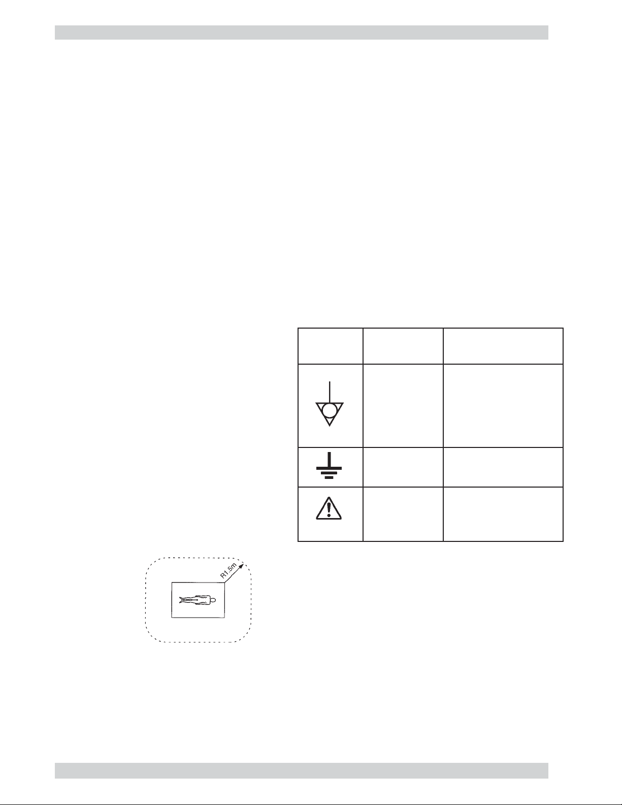
Symbols Location
Rear panel
of monitor
Rear panel
of monitor
Rear panel of
monitor and
power bar
This Symbol
Indicates
The equipotential
terminal which brings
the various parts of a
system to the same
potential.
Functional earth
terminal
Attention, consult
ACCOMPANYING
DOCUMENTS
*Patient Area
3) The leakage current could increase when connected to other equipment.
4) The operator should take precautions to avoid touching the rear panel input and output circuitry and the
patient at the same time.
5) The main power switch of the system is not easily accessible. To isolate the system from the mains supply
remove the mains plug from the wall socket.
4

Health Care System III
Warning on power connection
Use a proper power cord for your local power supply. NEVER USE AN EXTENSION CABLE TO POWER
THE SYSTEM.
United States Canada Continental Europe
Plug type Hospital Grade Hospital Grade LP-34A
Female end E41395 LL33182 LS-60
Cord type E41395-A LL76662 H05VV-F
Safety approval 10A/125V 10A/125V 10A/250V
Minimum cord set rating UL CSA VDE
Precautions
On Safety
For your protection, please read these safety instructions completely before operating the equipment and
keep this manual for future reference. The information in this summary is intended for persons who operate
the equipment as well as repair personnel. Carefully observe all warnings, precautions and instructions on the
apparatus, or the one described in the operating instructions and adhere to them. Also for your protection, the
instruction manual for the monitor, LCD display (optional), mobile camera (optional) are provided.
Operate the unit on 120 or 240 VAC only, as indicated on the nameplate of the system, which is located on
the side of the housing compartment at the bottom of the cart.
Should any solid object or liquid fall into the cabinet, unplug the unit and have it checked by qualified
personnel before operating it any further.
Unplug the system from the wall outlet during lightning storms or if it is not to be used for several days or
more.
To disconnect the system main power cord, pull it out by grasping the plug. Never pull the cord itself.
The socket-outlet shall be installed near the equipment and shall be easily accessible.
Be sure to connect the main power cord to a grounded outlet.
Do not use attachments not recommended by the manufacturer, as they may cause hazards.
On Installation
Allow adequate air circulation to prevent internal heat build-up. Do not block any of the ventilation openings
of the apparatus.
Do not install the system in a location near heat sources such as radiators or air ducts, or in a place subject to
direct sunlight, excessive dust, mechanical vibration or shock.
Route the power cord to avoid it being walked on or pinched by items placed on or against it, paying
particular attention to the plug, receptacle, and the point where the cord enters the unit.
5

Health Care System III
On Cleaning
To keep the system looking brand new, periodically clean it with a mild detergent solution. Never use strong
solvents such as thinner or benzine, or abrasive cleaners since they will damage the cabinet. As a safety
precaution, unplug the system before cleaning it. Never attempt to sterilize this unit. If required to be used in
a sterilized environment, use suitable protective covers.
On Repacking
Do not throw away the carton and packing materials. They make an ideal container which to transport the
system.
On Mobility
Before moving the system, ensure that the monitor is secured to the table by the attaching clips.
Do not use the monitor handles or any other part of the cart to move it. Use only the identified handles on the
table for this purpose.
To prevent impact damage to the LCD display while moving the cart, position the display as close as possible
toward the cart.
On Storage
If you need to store the system, ensure that it is stored in a controlled environment* to avoid damage.
*Controlled environment 10 - 40°C (50 - 104°F) 10 - 60% relative humidity
6

Health Care System III
Contents
Declaration of Conformity ............................................................................................................................................2
Warning .........................................................................................................................................................................4
For the customers in the USA ..............................................................................................................................4
Important safeguards/notices for use in the medical environments .....................................................................4
Warning on power connection .............................................................................................................................. 5
Precautions ....................................................................................................................................................................5
On Safety .............................................................................................................................................................. 5
On Installation ......................................................................................................................................................5
On Cleaning .........................................................................................................................................................6
On Repacking .......................................................................................................................................................6
On Mobility ..........................................................................................................................................................6
On Storage ............................................................................................................................................................ 6
Introduction................................................................................................................ 12
At a Glance — The HCS III System ........................................................................................................................... 13
Main HCS III Cart ...................................................................................................................................................... 14
Camera ...............................................................................................................................................................14
Microphone ........................................................................................................................................................ 14
Monitor ............................................................................................................................................................... 14
LCD Display ...................................................................................................................................................... 14
PC (customer supplied) ......................................................................................................................................14
Keyboard and Mouse (customer supplied) ........................................................................................................15
Cart .....................................................................................................................................................................15
Headset and Jack ................................................................................................................................................16
Rear Interface Panel ...........................................................................................................................................16
Remote Control ..................................................................................................................................................16
Network Terminating Units ................................................................................................................................16
Mobile Camera Cart (optional) ...................................................................................................................................17
Camera ...............................................................................................................................................................17
Cart .....................................................................................................................................................................17
Height Adjustable Camera Arm .........................................................................................................................17
Installation .................................................................................................................. 19
Precautions ..................................................................................................................................................................19
Unpacking ...................................................................................................................................................................19
Connecting the System ............................................................................................................................................... 20
Rear Interface Panel ...........................................................................................................................................22
VCR .................................................................................................................................................................... 22
To connect a video cassette recorder (VCR) ......................................................................................................22
Dual ....................................................................................................................................................................23
ISDN BRI Cables ............................................................................................................................................24
NET 1 External Network Interface .................................................................................................................24
PRI Interface ...................................................................................................................................................24
LAN Cable ...................................................................................................................................................... 24
Mobile Camera Cart Cable .............................................................................................................................. 24
Microphone 3 (MIC 3) ....................................................................................................................................25
Installing a PC ....................................................................................................................................................25
Main HCS III Cart Microphone .........................................................................................................................25
Ancillary Equipment ..........................................................................................................................................26
Cart Adjustments.........................................................................................................................................................27
Triple-pivot Arm Counterbalance Adjustment ................................................................................................... 27
Monitor Suspension Arm Adjustment ................................................................................................................27
Operational Considerations.........................................................................................................................................28
Iris Control and Lighting .................................................................................................................................... 28
Brightness Control .............................................................................................................................................28
Loudspeaker Volume .......................................................................................................................................... 28
Background ........................................................................................................................................................ 28
Guidelines for setting up videoconferencing rooms ..........................................................................................29
7

Health Care System III
Getting Started ........................................................................................................... 30
System start-up ...........................................................................................................................................................30
Welcome menu ............................................................................................................................................................ 30
Basics ..........................................................................................................................................................................31
Menu Structure ...........................................................................................................................................................32
System configuration .........................................................................................................................................33
ISDN configuration ............................................................................................................................................34
LAN configuration .............................................................................................................................................34
Making and ending calls .............................................................................................................................................35
Making a call ......................................................................................................................................................35
ISDN call ......................................................................................................................................................... 35
LAN call ..........................................................................................................................................................35
Access Code ....................................................................................................................................................35
Using sub-address / extension address / MCU password ................................................................................ 35
Selecting / setting default quality (bandwidth) ..................................................................................................36
Selecting / setting default network .....................................................................................................................37
Answer a call ......................................................................................................................................................37
End a call ............................................................................................................................................................37
Correcting keying mistakes ................................................................................................................................37
Directory .....................................................................................................................................................................38
Add New Entry ..................................................................................................................................................39
Delete Entry .......................................................................................................................................................39
Edit Entry ........................................................................................................................................................... 39
Delete Entry .......................................................................................................................................................39
Add MultiSite Entry ...........................................................................................................................................40
Add Site .............................................................................................................................................................. 40
General use ................................................................................................................. 41
Adjusting volume ........................................................................................................................................................ 41
View outgoing video (selfview)..................................................................................................................................41
Microphone on/off ......................................................................................................................................................41
Do Not Disturb / Sleep Mode ..................................................................................................................................... 41
Controlling the Main Camera ..................................................................................................................................... 42
Moving / zooming camera .................................................................................................................................42
Focusing camera ................................................................................................................................................. 42
Selecting video sources ............................................................................................................................................... 42
Voice Activated Camera Positioning ..........................................................................................................................43
Setup ................................................................................................................................................................... 43
Activating ...........................................................................................................................................................43
Deactivating .......................................................................................................................................................43
Presets .........................................................................................................................................................................44
Selecting presets .................................................................................................................................................44
Storing presets ....................................................................................................................................................44
Far end camera control (FECC) ..................................................................................................................................44
Sending/receiving still images ....................................................................................................................................45
Sending a still image ..........................................................................................................................................45
Viewing a still image..........................................................................................................................................45
Receiving a still image .......................................................................................................................................45
Requesting a still image ..................................................................................................................................... 45
Duo Video ...................................................................................................................................................................46
Add Duo Video ................................................................................................................................................... 46
End a Duo Video call ......................................................................................................................................... 47
Controlling camera, changing video source, presets in a Duo Video call ..........................................................47
MultiSite (MCU).........................................................................................................................................................48
MultiSite cascading ............................................................................................................................................49
Establishing MultiSite meetings using Directory ..............................................................................................49
Adding an extra site - dial out ............................................................................................................................50
Adding an extra site - dial in ..............................................................................................................................51
Disconnecting sites from a conference...............................................................................................................51
PC Presenter ................................................................................................................................................................ 52
PC SoftPresenter .........................................................................................................................................................52
8

Health Care System III
Web-interface ..............................................................................................................................................................53
Text Chat / Closed Captioning ........................................................................................................................... 53
Streaming ...........................................................................................................................................................54
T.120 and other PC applications ................................................................................................................................. 54
Advanced use .............................................................................................................. 55
Main menu ..................................................................................................................................................................55
Call quality .................................................................................................................................................................. 56
Audio ..................................................................................................................................................................56
Video ..................................................................................................................................................................56
Natural Video ..................................................................................................................................................... 56
VGA Resolutions ...............................................................................................................................................56
Advanced call quality ......................................................................................................................................... 57
Audio ...............................................................................................................................................................57
Video ...............................................................................................................................................................57
Resolution ........................................................................................................................................................ 57
H.331 ...............................................................................................................................................................57
Status Format ................................................................................................................................................... 57
Presentations ...............................................................................................................................................................58
Presentation Mode .............................................................................................................................................. 58
Duo Video Quality ............................................................................................................................................. 58
Duo Video Mode ................................................................................................................................................58
Duo Video Number ............................................................................................................................................ 58
Duo Video / Still Image source .......................................................................................................................... 58
Auto-display still image .....................................................................................................................................59
Still image filter .................................................................................................................................................. 59
Utilities........................................................................................................................................................................59
Autoanswer ........................................................................................................................................................59
Far end camera control .......................................................................................................................................59
Dual Monitor ......................................................................................................................................................59
Auto-PIP ............................................................................................................................................................. 59
Welcome Menu .................................................................................................................................................. 60
Continuous Presence ..........................................................................................................................................60
MCU status line .................................................................................................................................................. 60
System Name .....................................................................................................................................................61
MCU services .............................................................................................................................................................61
Quick Menu ........................................................................................................................................................ 62
When connected to an MCU ...........................................................................................................................62
When MultiSite ............................................................................................................................................... 62
Request floor ......................................................................................................................................................62
Release floor....................................................................................................................................................... 62
Terminal Names .................................................................................................................................................62
View site # .......................................................................................................................................................... 62
End view............................................................................................................................................................. 62
Chair control....................................................................................................................................................... 63
Take chair ........................................................................................................................................................63
Release chair ...................................................................................................................................................63
Floor to site # ................................................................................................................................................... 63
Release Floor To Site.......................................................................................................................................63
Disconnect site # .............................................................................................................................................63
Terminate meeting ...........................................................................................................................................63
Audio Settings.............................................................................................................................................................64
Audio Inputs .......................................................................................................................................................64
Mix Mode ........................................................................................................................................................64
Level Settings ..................................................................................................................................................65
Audio Outputs ....................................................................................................................................................65
Level Settings - Outputs ..................................................................................................................................66
Echo Control ...................................................................................................................................................... 66
Noise Reduction ..............................................................................................................................................66
Room Size ....................................................................................................................................................... 67
Motion .............................................................................................................................................................67
Automatic Gain Control (AGC) Settings ...........................................................................................................67
Tips for improving the echo canceller performance: .........................................................................................68
Alert Tones & Volume........................................................................................................................................68
Alert Speaker ...................................................................................................................................................68
Restore Audio Defaults ......................................................................................................................................68
9

Health Care System III
Video Settings .............................................................................................................................................................69
Camera Tracking Mode ......................................................................................................................................69
Document Camera .............................................................................................................................................. 69
PC .......................................................................................................................................................................69
Focus .................................................................................................................................................................. 69
Brightness ........................................................................................................................................................... 69
Whitebalance ......................................................................................................................................................69
Video Name........................................................................................................................................................70
VGA Settings .....................................................................................................................................................70
VGA Out .........................................................................................................................................................70
VGA Out Quality ............................................................................................................................................70
VNC Settings .....................................................................................................................................................71
Address ............................................................................................................................................................71
Display Number ..............................................................................................................................................71
Password .......................................................................................................................................................... 71
Start using VNC .............................................................................................................................................. 71
Terminal Settings ........................................................................................................................................................ 72
Network Configuration ...............................................................................................................................................72
ISDN-BRI Settings ............................................................................................................................................. 73
ISDN Switch Type ........................................................................................................................................... 73
Line Setup .......................................................................................................................................................74
Advanced ISDN settings .................................................................................................................................75
ISDN-PRI Settings .............................................................................................................................................76
Number ............................................................................................................................................................76
PRI Switch Type ..............................................................................................................................................76
Channel Hunting .............................................................................................................................................77
Line Settings .................................................................................................................................................... 78
Advanced ISDN Settings ................................................................................................................................78
Advanced ISDN-PRI Settings .........................................................................................................................78
Leased E1/T1 Settings ........................................................................................................................................ 79
Network Interface ............................................................................................................................................ 79
Max Channels .................................................................................................................................................. 79
Start Channel ...................................................................................................................................................79
T1 Line Coding ...............................................................................................................................................79
Line Settings .................................................................................................................................................... 79
External network settings ...................................................................................................................................79
Call control ......................................................................................................................................................80
Network clocking ............................................................................................................................................80
LAN Settings .............................................................................................................................................................. 81
Streaming ...........................................................................................................................................................81
Address ............................................................................................................................................................81
Address Port ....................................................................................................................................................81
TTL/Router Hops ............................................................................................................................................81
Streaming Source ............................................................................................................................................81
Allow Remote Start .........................................................................................................................................81
Announcements ...............................................................................................................................................82
Video Rate .......................................................................................................................................................82
Password .......................................................................................................................................................... 82
Start/Stop Streaming .......................................................................................................................................82
How to view streaming ...................................................................................................................................82
H.323 Settings ....................................................................................................................................................82
E.164 alias .......................................................................................................................................................82
Use Gatekeeper................................................................................................................................................82
Gatekeeper IP-address .....................................................................................................................................82
H.323 Prefix .................................................................................................................................................... 83
Register............................................................................................................................................................ 83
Advanced H.323 Settings ...................................................................................................................................83
IP Precedence ..................................................................................................................................................83
IP Type of Service (TOS) ................................................................................................................................83
RSVP ...............................................................................................................................................................83
NAT .................................................................................................................................................................84
NAT Address ................................................................................................................................................... 84
IP Settings...........................................................................................................................................................84
IP-assignment ..................................................................................................................................................84
IP-address ........................................................................................................................................................84
IP-subnet mask ................................................................................................................................................84
Gateway ........................................................................................................................................................... 85
10

Health Care System III
Ethernet Speed ................................................................................................................................................. 85
Restart ................................................................................................................................................................85
SNMP Settings ................................................................................................................................................... 85
SNMP Trap Host .............................................................................................................................................85
SNMP Community .......................................................................................................................................... 85
Call Settings ................................................................................................................................................................86
Incoming MCU calls ..........................................................................................................................................86
Incoming telephone calls .................................................................................................................................... 86
Fallback to telephony .........................................................................................................................................86
Access Code .......................................................................................................................................................86
Encryption ..........................................................................................................................................................87
Max Call Length ................................................................................................................................................87
Network Profiles ................................................................................................................................................ 87
Dataport configuration ................................................................................................................................................88
Dataport 1 ...........................................................................................................................................................88
Data mode .......................................................................................................................................................88
Control mode ................................................................................................................................................... 88
Modem mode ................................................................................................................................................... 88
T.120 ................................................................................................................................................................88
Dataport 2 ........................................................................................................................................................89
Language ..................................................................................................................................................................... 89
Software Options ........................................................................................................................................................89
Diagnostics..................................................................................................................................................................90
System info ......................................................................................................................................................... 90
Channel status ....................................................................................................................................................90
Call status ...........................................................................................................................................................91
Restore defaults ..................................................................................................................................................91
Test subsystem .................................................................................................................................................... 92
Far End Loop (ISDN only) .............................................................................................................................. 92
System Selftest ................................................................................................................................................92
View current settings.......................................................................................................................................... 92
Appendix 1.................................................................................................................. 93
Connecting the HCS III to ISDN using Network Adapters ........................................................................................93
Connecting .........................................................................................................................................................93
Configuring ........................................................................................................................................................ 93
Appendix 2.................................................................................................................. 94
Using Telesync TS-256 SW56/ISDN adapter ....................................................................................................94
Connecting .........................................................................................................................................................94
Configuration of Telesync Adapter ....................................................................................................................94
Configuration of the system ...............................................................................................................................94
How to call .........................................................................................................................................................94
Appendix 3.................................................................................................................. 95
Connecting the system to PRI/T1 ...............................................................................................................................95
Using CSU adapter ............................................................................................................................................. 95
Connecting to Adtran T1 ESF CSU ACE...........................................................................................................95
Configuration of the system ...............................................................................................................................95
Configuration of Adtran T1 ESF CSU ACE ...................................................................................................... 96
Appendix 4.................................................................................................................. 97
Environmental considerations.....................................................................................................................................97
Iris control and lighting ......................................................................................................................................97
Background ........................................................................................................................................................ 97
Loudspeaker volume ..........................................................................................................................................97
Appendix 5.................................................................................................................. 98
Using the file system...................................................................................................................................................98
Appendix 6: Access Code .......................................................................................... 99
Technical Description .............................................................................................. 100
Abbreviations ........................................................................................................... 103
Index ......................................................................................................................... 104
Servicing ................................................................................................................... 106
11

Health Care System IIIIntroduction
Introduction
This User Manual is provided to help you make the best use of your TANDBERG system. The system offers
superior quality audio and video in a fully-featured unit.
Main Features:
• Supports videoconferencing via both IP and ISDN networks.
• Selection of up to 3 Mbps call quality.
TF
• Built-in MultiSite
joint meetings, each benefiting from the same superb audio and video quality. Both Continuous Presence
and Voice Switched mode is supported. A combination of ISDN and IP participants is possible. The
TANDBERG videoconferencing system can also be used purely as an audio-bridge (with an ISDN
connection).
• Embedded encryption for call privacy and security.
Natural Presenter Package* consisting of:
•
Duo VideoTF - allows participants at the far end to simultaneously watch a presenter on one screen and a
live presentation on the adjoining screen.
Digital ClarityTF - participants enjoy presentations of exceptionally high quality resolution video.
PC PresenterTF - an easily accessible PC connection plug.
PC SoftPresenterTF - show PC images via your LAN connection.
Natural VideoTF - 60 fields per second true interlaced picture.
•
DownspeedingTF - if channels are dropped during a videoconferencing session, the connection is
•
automatically maintained without interruption.
Streaming – allows broadcasting of audio/video via an IP network.
•
W.A.V.E (Wide Angle View) Camera - delivers the widest angle of view in the industry.
•
Natural Audio ModuleTM - specifically designed for videoconferencing, this audio system creates an
•
exceptionally realistic environment.
• Web-interface for streaming, text chat/closed captioning, system management, diagnostics and software
uploads.
Worldwide compatibility with other standards-based videoconferencing systems.
•
*- a maximum of 5 sites including a minimum of 1 telephone call can participate in
* - option. To check which options are installed, press MENU and the Quick key ‘System Info’.
TF- TANDBERG first.
12
TIP
IN THIS GUIDE, WE’VE INCLUDED
TIPS AND NOTES. THEY
HELPFUL
APPEAR LIKE THIS ONE.
Health Care System III
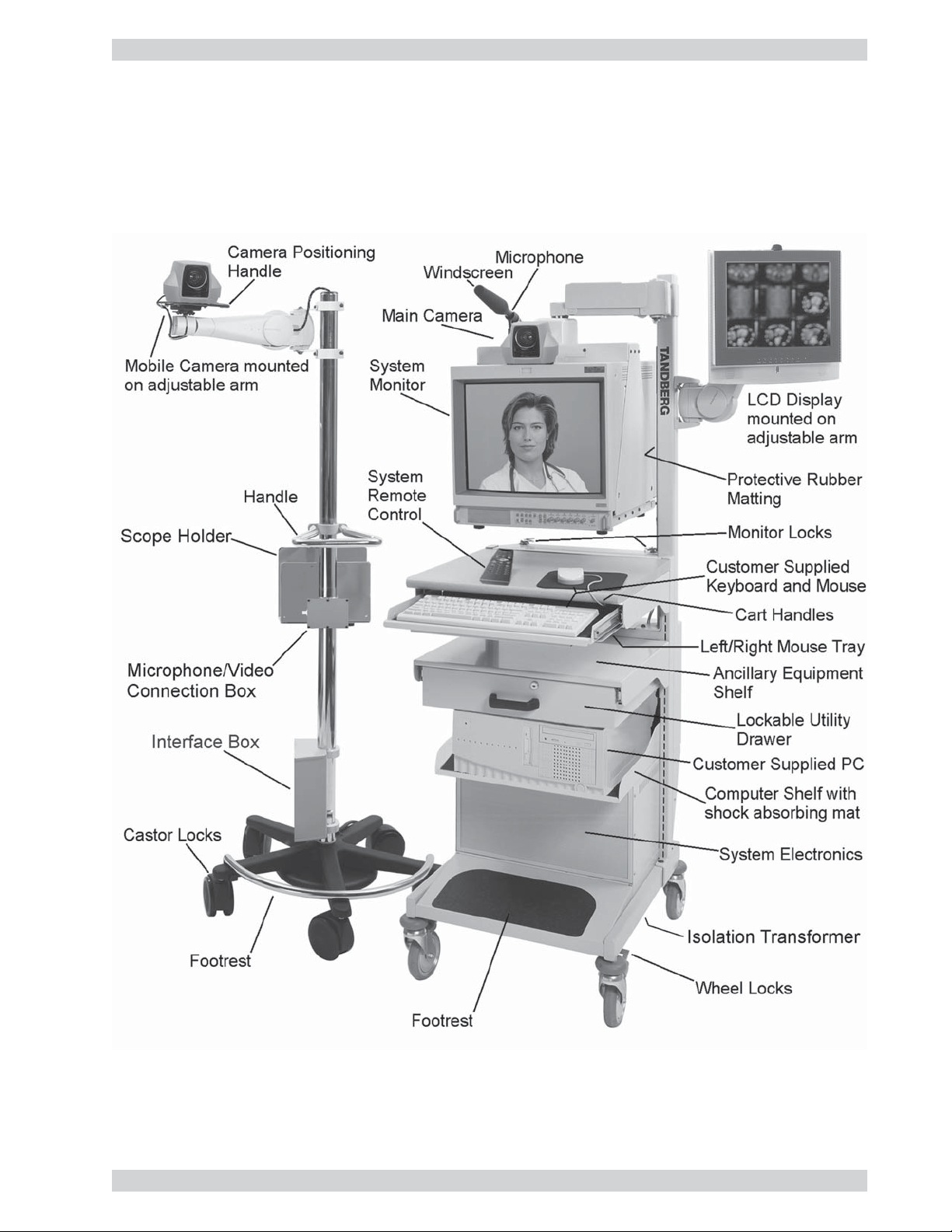
At a Glance — The HCS III System
Introduction
13

Health Care System IIIIntroduction
Main HCS III Cart
Camera
The main WAVE (wide angle view) camera is mounted on top of the monitor and is continent specific
(NTSC for North America or PAL for Europe). It is a high quality colour camera with a fast pan/tilt/zoom
action. The camera is controlled by the system’s infrared remote control which operates pan/tilt, focus and
zoom. You can pre-store up to ten camera positions using the remote control.
Microphone
The standard TANDBERG HCS III Healthcare videoconferencing system is designed as a portable
diagnostics aid and communication tool that can be moved from examination room to examination room
within a medical facility. As such, it is intended for use where the person talking is within about 6 to 10 feet
of the system, and is in front of the system. Sometimes however, circumstances will require that the HCS III
be used in larger rooms, and/or with people speaking further away from it. In these instances, Tandberg
recommends using the “external microphone” supplied with the system.
Monitor
The monitor displays the far-end and near-end videoconferencing sites. The monitor is also used for
displaying the HCS III menus, on-screen help, video from connected video sources and still video images.
When the monitor is used for any HCS III function, Line B must be selected on the monitor’s control panel.
The monitor is suspended by the cart to allow swivel and tilt adjustment. If the cart is to be moved, the
monitor must be secured to the table below it using the attaching clips that are mounted at the rear of the
table.
Warning
For more information concerning the mobility of the system, see Precautions on pages 5 and 6.
LCD Display
The LCD display is used for dual monitor mode and the customer supplied PC. It supports 16 million colours
in VGA, SVGA, and XGA pixel formats. It has anti-glare coating and is mounted on a fully adjustable arm
that allows for easy viewing. Controls for the display are located at the bottom of the front panel. Refer to the
LCD User Manual for further information.
PC (customer supplied)
The customer supplied PC (with video capture card, if required) is placed on the shelf just below the utility
drawer. All the required audio, video, and communication cables for the computer are permanently installed
on the cart. A desktop (not tower) style PC is intended for placement on the shelf. Other specifications for
this PC are based on customer requirements and not the HCS III system.
Warning
14
The safety of the system could be compromised if the PC is not certified
and installed as per indicated under the Warning section on pages 4 and 5.

Health Care System III
Introduction
Keyboard and Mouse (customer supplied)
The customer supplied keyboard is placed within the retractable tray below the table top. The customer
supplied mouse can be placed on the table top or the mouse tray that is retractable from beneath the left or
right side of the keyboard tray. When moving the cart, store the mouse behind the keyboard, retract the
mouse tray and retract the keyboard tray fully under the table.
Cart
The cart is designed to house all the equipment in a minimal amount of space. Its large wheels provide quick
and easy mobility. To move cart, use the handles underneath the front of the table top. To keep the cart in
place, press the foot locks on each wheel.
Warning
For more information concerning the mobility of the system, see Precautions on pages 5 and 6.
The cart supports the monitor, camera, and microphone with an adjustable arm that allows their movement
after the cart has been locked in place. Rubber padding on the monitor support post protects the monitor in
case it is pushed against the post. An Allen key is stored on top of the monitor in case the supporting arm
needs adjustment. The same Allen key can also be used for adjusting the LCD display mounting arm, and the
camera mounting arm on the optional mobile camera cart.
The ancillary equipment shelf and utility drawer assembly is positioned at a standard height between the
computer shelf and keyboard tray. The utility drawer can be locked to provide a safe storage area. It normally
contains the documentation for the HCS III components from the various manufacturers.
The computer shelf is positioned just below the utility box. The shelf is covered with a shock absorbing pad
to keep the PC steady when the cart is moved. The pad should not be removed. A four receptacle power bar is
located at the rear of the shelf, and has hospital grade type receptacles for North America or IEC type
receptacles for Europe. It can supply a maximum of 480 watts to the customer supplied PC, VCR and other
hospital approved ancillary equipment. Power to the bar is supplied by the isolation transformer located at
the bottom of the cart.
Warning
The safety of the system could be compromised if the ancillary equipment is not
certified and installed as per indicated under the Warning section on pages 4 and 5.
The system electronics are located within the enclosed area at the bottom of the cart. There are no user
serviceable parts inside. There is a main power switch on the isolation transformer at the bottom of the cart
that is not considered user accessible, and is normally left on. In North America, the main power cable uses a
hospital grade plug. The main HCS III cart provides a grounding stud at the bottom left corner of the
monitor’s rear panel (refer to the Sony monitor user manual).
15
Health Care System IIIIntroduction
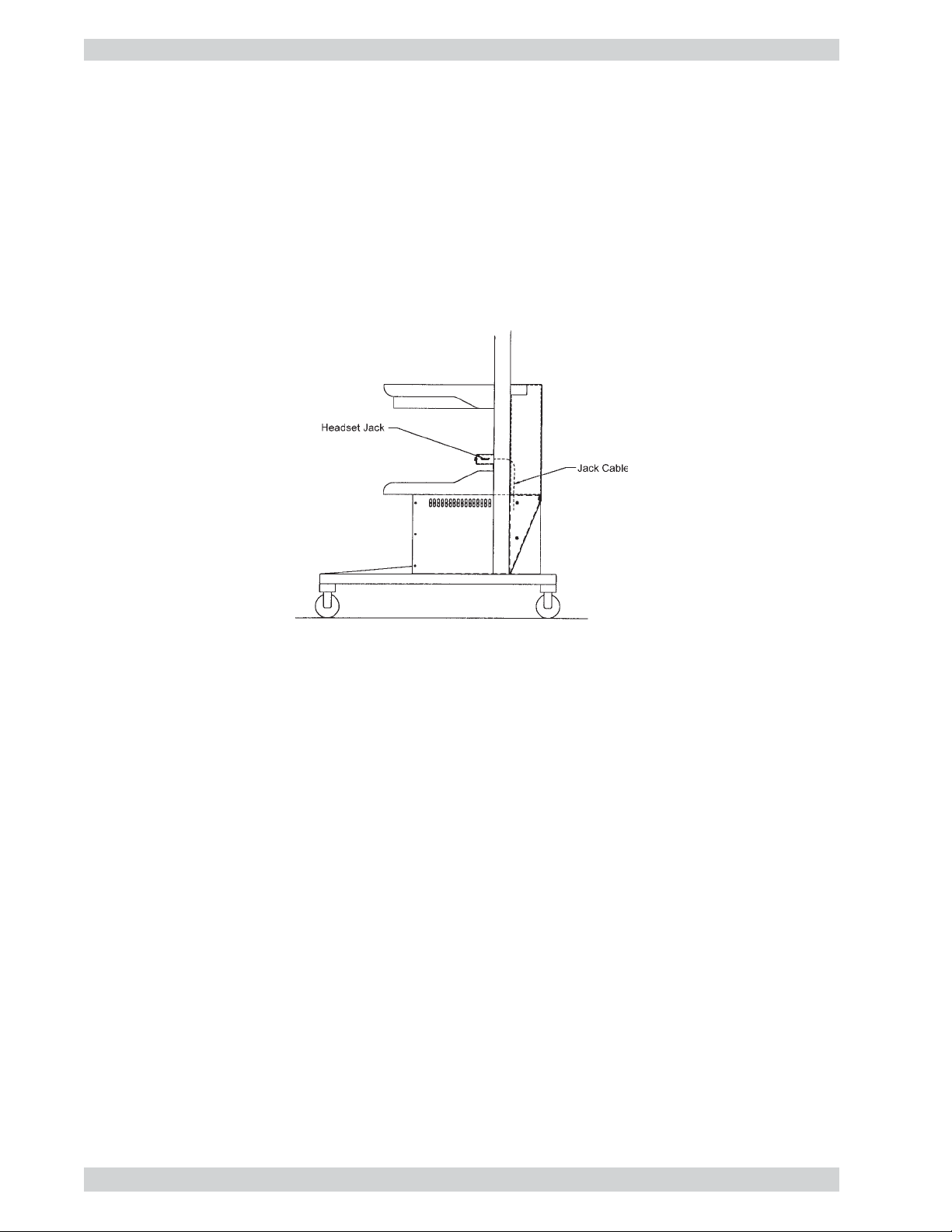
Headset and Jack
The headset can be used as an alternative to the main system speakers. When the headset is plugged into the
jack that is mounted on the cart post above the computer shelf, the audio is cut from the system speakers and
is routed to the headset. The other system audio outputs are not affected by the operation of the headset.
Typically, a physician will use the headset to keep all incoming audio private. A headset extension cable is
also supplied so that the headset can be used in conjuction with the optional mobile camera cart.
Warning
Use only the Tandberg supplied AKG model K141 headset and extension cable.
Rear Interface Panel
The rear interface panel provides the interface to other equipment and the switched digital communications
network. On the bottom of the panel is a cable wrap bracket. When moving the cart, all cables must be
wrapped around this bracket and securely fastened.
Remote Control
The TANDBERG remote control is used to control all functions of the HCS III.
Network Terminating Units
In North America, to use the six ISDN BRI interfaces provided on the main HCS III cart, network
terminating units must be used to connect the HCS III system the public ISDN network. When network
terminating units are required, two Inter-Tel Inc. model NT384 are installed within the enclosed area at the
bottom of the cart. See Appendix 1 for more information on these units.
16

Health Care System III
Introduction
Mobile Camera Cart (optional)
Camera
A standard, continent specific (NTSC for North America or PAL for Europe) TANDBERG WAVE camera is
mounted on a fully adjustable arm on the mobile stand. The camera provides high resolution images with a
fast pan/tilt/zoom action that is controlled from the Tandberg remote control. Up to ten camera positions can
be stored. To move the camera, always hold it by the handle and not its body.
Cart
The mobile camera cart provides excellent stability, the necessary height for the camera, and allows for easy
movement in confined areas. A large handle is provided midway along the main support post. Five castors
are used for stability and two of them can be locked by stepping on the foot lock. The bar above three of the
castors is provided for a foot rest.
A shelf is provided for holding other hospital approved specialized cameras for attaching to medical devices
such as otoscopes, opthalmascopes, etc. To securely hold various sized equipment, the width of shelf is
adjustable by loosening and tightening the two large thumbnuts underneath the shelf. The back of the shelf is
also used for holding the mobile camera remote control.
The hospital approved equipment that is used with the mobile cart must be plugged into either the power bar
within the main HCS III cart, or into the same receptacle that the power cord of the main HCS III cart is
plugged into.
A microphone/video connection box located at the back of the shelf, provides one video input connection and
one microphone connection. A short video cable is provided to attach a medical device on the shelf to the
video input connector. The microphone input is typically used for a microphone that is clamped to the cart
handle, such as that provided in the optional microphone package (described in next section).
The box at the bottom of the cart holds the connectors for the main unit-to-unit cable, as well as the mobile
camera control device.
Height Adjustable Camera Arm
The height adjustable camera arm clamp incorporates two
release handles and provides the camera with approximately
39 inches of vertical movement. This enables a physician to
have precise placement of the camera all the way down to the
height of an examination table.
Relative to the floor, the height of the camera lens can be
adjusted from approximately 45 inches (with camera lens
fully tilted up) to 83 inches.
Release
Handles
Height
Adjustable
Arm Clamp
Arm Clamp
Limit Collar
Cable Holder
Arm Clamp
Limit Collar
17

Health Care System IIIIntroduction
To adjust the camera arm height, support the arm with one hand and loosen the two release handles only
enough to permit movement of the arm, and carefully move the arm up or down to the required height.
Securely tighten both release handles.
Warning
Do not loosen the two release handles without supporting
the arm, as the arm may drop quickly and cause injury.
18

Health Care System III
Installation
Installation
Precautions
• Never install telephone wiring during a lightning storm.
• Never install telephone jacks in wet locations unless the jack is specifically designed for wet locations.
• Never touch uninstalled telephone wires or terminals unless the telephone line has been disconnected at
the network interface.
• Use caution when installing or modifying telephone lines.
• Avoid using a telephone (other than a cordless type) during an electrical storm. There may be a remote
risk of electrical shock from lightning.
• Do not use the telephone to report a gas leak in the vicinity of the leak.
• The socket outlet shall be installed near to the equipment and shall be easily accessible.
• Never do any installation of cables without first unplugging the main HCS III cart power cord.
• 1TR6 network type is not approved for connection directly to the telecommunications network. This
network type is only to be used behind a PABX.
• X.21 network type is not approved for connection directly to the telecommunications network. This
network type is only to be used together with already approved equipment, and is not meant for direct
connections to the telecommunication networks.
• V.35/RS-449/RS-366 network type is not approved for connection directly to the telecommunications
network. This network type is only to be used together with already approved equipment, and is not
intended for direct connection to the telecommunication networks.
Unpacking
The main HCS III cart is delivered in one crate. The optional mobile camera cart is delivered separately, in
its own crate. The equipment is unpacked as follows:
1) Remove the steel straps from the crate.
2) Remove the top cover by lifting it up and off the two side panels.
3) Remove the outer side panel by lifting it out from the skid and away from the unit. Remove the inner
side panel the same way.
4) Remove the unit’s right side Styrofoam packing by carefully pulling it away from the unit along the
entire height.
5) Remove the unit’s left side Styrofoam packing by raising the camera arm by 90 degrees so that it is
horizontal. Do not rotate the display because it must be narrow to fit through the opening in the
Styrofoam. Carefully pull the Styrofoam away from the unit.
19

Health Care System IIIInstallation
6) Remove the ramp that is located under the unit and place it against the front of the skid. With one person
holding the left side of the unit, and one person holding the right side of the unit, roll and guide the unit
off the skid and down the ramp.
7) We recommend that you store all the packing material specifically designed for this unit, in case the need
should arise to transport the system to another location.
The HCS III consists of the following items:
• Main cart
• Mobile camera cart (optional)
• Headset and jack
The utility drawer on the main cart contains the following:
• Microphone
• Remote control
• Batteries
• User manuals
• Short video cable
• Stick-on cable tie bases and loose cable ties
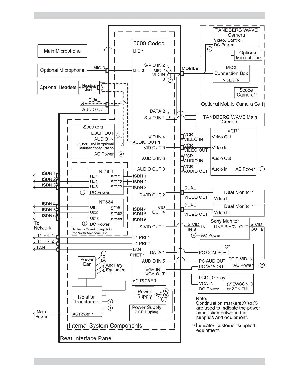
Connecting the System
The following block diagram provides an overview of the cabling connections that are required for the main
HCS III cart and optional equipment. Before installing the system’s cables and components, make sure that
the cart’s main power plug is unplugged from any power source.
20
Health Care System III
Installation
21
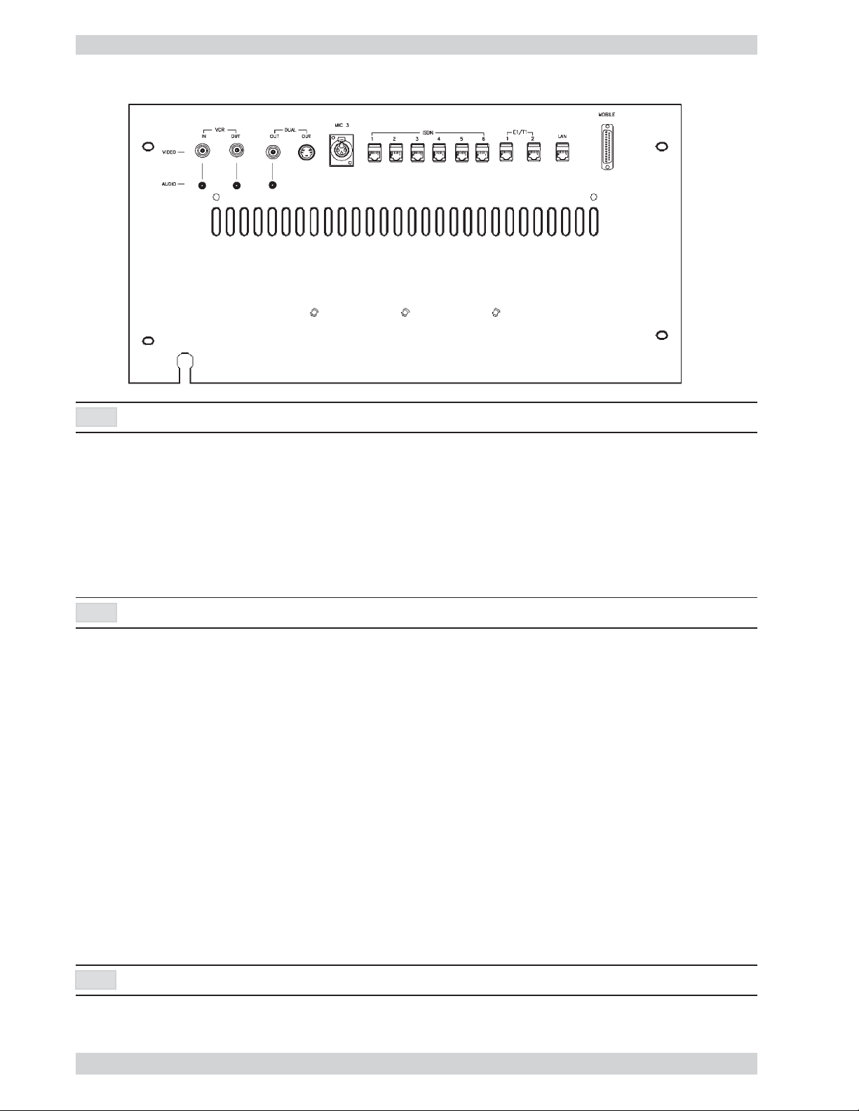
Rear Interface Panel
Health Care System IIIInstallation
NOTE
IF EQUIPED WITH THE ZENITH LCD DISPLAY, THE DUAL OUT S-VIDEO CONNECTOR WILL NOT BE AVAI L A B L E
VCR
• 1 video input supporting composite signals through a BNC connector (Video In 4 on Codec).
• 1 video output supporting composite signals through a BNC connector (Video Out 3 on Codec).
• 1 audio input (line level) via an RCA connector (Audio In 6 on Codec).
• 1 audio output (line level) via an RCA connector (Audio Out 3 on Codec).
NOTE
USE CABLE TIES TO NEATLY SECURE AND STOW CABLES WHEN REQUIRED.
Warning
Any equipment that is connected to VCR 1 must be powered from either the cart’s internal
isolated power bar or an external isolated transformer, as per the requirements indicated on
pages 4 and 5 under Warning.
To connect a video cassette recorder (VCR)
A VCR is used for sending and recording video sequences. When recording, a VCR will record the incoming
video, the local audio and the audio from the remote side.
Place a VCR onto the shelf above the utility drawer. Connect the VCR’s power cord to the cart’s isolated
power bar located at the back of the PC shelf, as follows:
1) Remove the back panel from the cart’s PC shelf by removing the two screws on the panel’s bottom
corners, and then removing the two screws on the panel top.
2) Remove the cable entry cover from the post.
NOTE
USE CABLE TIES TO NEATLY SECURE AND STOW CABLES WHEN REQUIRED.
22

Health Care System III
Installation
3) Feed the power cord down into the post and out to the power bar. Plug the power cord into the cart’s
isolated power bar.
4) Re-install the cable entry cover and the back panel on the cart.
Connect the VCR cables to VCR on the rear interface panel as follows:
1) Connect a video cable between Video Out on the VCR and VCR VIDEO IN.
2) Connect a video cable between Video In on the VCR and VCR VIDEO OUT.
3) Connect an audio cable between Audio Out on the VCR and VCR AUDIO IN.
4) Connect an audio cable between Audio In on the VCR and VCR AUDIO OUT.
vcr
For playback operation, press
on the remote control.
Make sure that ‘Audio6 (VCR)’ is ‘On’ (see ‘Inputs’ in the ‘Audio Settings’ menu). If the audio
from the VCR is too low, the level can be adjusted in ‘Level Settings’ in ‘Audio Settings’,
‘Inputs’.
The audio from the VCR will be sent to the other side and to the local speaker system.
For most VCRs, the default audio output settings will be set correctly. If adjustments are required, see section
‘Level Stettings’ in ‘Outputs’, ‘Audio Settings’.
Dual
• 1 video output signal through a S-Video connector (Video Out 2 on Codec).
• 1 video output signal through a BNC connector (Video Out 4 on Codec).
• 1 audio output (line level) via an RCA connector (LOOP OUT on speaker module).
NOTE
NOTE
USE CABLE TIES TO NEATLY SECURE AND STOW CABLES WHEN REQUIRED.
IF DUAL MONITOR SETTINGS IS SET TO VGA, NO OUTPUT WILL BE SEEN FROM THE DUAL VIDEO CONNECTORS.
The format of the video output will be either PAL or NTSC depending on your country’s standard video
format.
Warning
Any equipment that is connected to Dual must be powered from either the cart’s internal
isolated power bar or an external isolated transformer, as per the requirements indicated on
pages 4 and 5 under Warning.
23

Health Care System IIIInstallation
ISDN BRI Cables
Take the six ends of the ISDN BRI cables and verify that they are labelled ISDN 1, 2, 3, 4, 5 and 6.
Connect ISDN cable No. 1 to the first ISDN socket (S/T-interface) provided by the service provider. This will
be your main number. Connect ISDN cable No. 2 to the second ISDN socket, ISDN cable No. 3 to the third
ISDN socket, ISDN cable No. 4 to the fourth socket, ISDN cable No. 5 to the fifth socket and ISDN cable
No. 6 to the sixth socket.
North America: The HCS III does have built in network terminators as standard. If your wall socket provides you
with an ISDN S/T-interface, you will need to bypass network terminating units between your HCS III and the
ISDN lines, see Appendix 1.
NOTE
WRITE DOWN THE NUMBERS ASSOCIATED WITH EACH OF THE ISDN LINES. YOU WILL NEED THEM LATER TO CONFIGURE THE SYSTEM.
NET 1 External Network Interface
To connect the HCS III system to a network using the NET 1 connector provided on the Codec, proceed as
follows:
Remove the rear interface panel that is fastened with four screws, to gain entry to the Codec.
Route the required RS366/V35 cables up from the bottom of the cart, through the cable entry hole, and plug
the connector into the NET connector on the Codec. Tighten the two screws to secure the connector. Use
cable ties to secure the cable to the cart, to prevent any tension on the cables.
Connect the other end of the cable to the customer supplied CSU/DSU.
Re-install the rear interface panel with the four screws.
PRI Interface
If you are using the E1/T1 interface, the E1/T1 Port 1 cable must be connected to a CSU unit, see Appendix 3.
The E1/T1 Port 2 Cable is used to fascilitate the operation of two or more codecs in the same environment,
using only one incoming T1 PRI line. Refer to Appendix 3 for cabling instructions.
LAN Cable
Connect the LAN cable from the LAN port on the rear panel of the main HCS III cart, to a Local Area
Network. This LAN connection will allow H.323 type calls and control of the codec using a PC with
standard WWW-browser. See the section on Ethernet Functionality for futher instruction.
Mobile Camera Cart Cable
Connect the mobile camera cart cable to the MOBILE connector on the rear panel of the main HCS III cart,
and fasten the connector with the two thumb screws.
24

Health Care System III
Installation
Microphone 3 (MIC 3)
Connect an additional microphone as required, to this connector. By default, this input is active.
Installing a PC
To install a PC on the cart, proceed as follows.
1) Remove the back panel from the cart’s PC shelf by removing the two screws on the panel’s bottom
corners, and then removing the two screws on the panel top.
2) Place the PC on the shelf close to the back, leaving only enough room for the cables between the PC and
the rear panel of the cart.
3) Place the keyboard and mouse on their respective shelves and route their cables from the rear of the
keyboard shelf to the cart post. Remove the cable entry cover from the post and feed the cables down
into the post and out to the PC. Plug the keyboard and mouse cables into their respective connectors on
the PC. Re-install the cable entry cover on the post.
NOTE
USE CABLE TIES TO NEATLY SECURE AND STOW CABLES WHEN REQUIRED.
4) Connect the four cables that are permanently installed on the cart to the PC as follows:
Remove the terminator labelled S-VIDEO TERMINATOR from the cable connector labelled
PC S-VID IN and connect the cable to the ‘S’ video input on the PC.
NOTE
IF THE PC IS EVER REMOVED OR DISCONNECTED, THE S-VIDEO TERMINATOR MUST BE RECONNECTED TO THE PC S-VID IN CABLE.
Connect the cable labelled PC VGA OUT to the monitor output connector on the PC.
Connect the cable labelled PC COM PORT to the RS-232 communication connector on the PC.
Connect the cable labelled PC AUD OUT to the audio output connector on the PC.
5) Connect the power cable (supplied with PC) from the PC to the power bar at the rear of the PC shelf.
6) Re-install the back panel on the cart.
Main HCS III Cart Microphone
Remove the microphone from its shipping box (stored in utility drawer), and connect it to its receptacle on
top of the monitor. Snap the body (black area) of the microphone into the mounting adapter. Ensure that the
low frequency cutoff switch is in the normal position indicated by “ - ”. Slip the windscreen fully onto the
microphone, and adjust the microphone direction as necessary.
Adding an external microphone to the HCS III:
1) Place the table microphone on a flat surface or table.
2) Plug the microphone into the microphone connector labelled as Mic 3 at the back of the HCS III cart.
25

Health Care System IIIInstallation
Enable the external microphone within the system setup menu as follows:
3) With the TANDBERG I/R remote control, press the “MENU” button.
4) Highlight the Audio Setup option, and press “OK.”
5) Highlight the Inputs option, and press “OK.”
6) Turn off the Mic 1 input. This is to prevent signal cancellation that may occur when a second
microphone (not in use) picks up the same sounds as that of the “active microphone.”
7) Make sure that the Mic 3 input is on.
8) Still in the Inputs menu, highlight the Level Settings option, and press “OK.”
9) If using a table microphone, set the gain of Mic 3 to “+3.0 dB.”
10) After setting the gains, press the “MENU” button to exit the menu.
The system is now ready for use with the external microphone.
To use the HCS III without the external microphone, unplug the external microphone from the cart. Then reactivate the standard microphone by repeating steps 3 to 6 above, except now turn on the Mic 1 input.
Ancillary Equipment
Warning
Any ancillary equipment that is to be used with the HCS III must be powered from either the
cart’s internal isolated power bar or an external isolated transformer, as per the requirements
indicated on pages 4 and 5 under Warning.
Install ancillary equipment as follows:
1) Place equipment onto the shelf above the utility drawer.
2) Connect the required cables from the ancillary equipment to the rear interface panel. Connect the
equipment’s power cord to the cart’s isolated power bar located at the back of the PC shelf, as follows:
i) Remove the back panel from the cart’s PC shelf by removing the two screws on the panel’s bottom
corners, and then removing the two screws on the panel top.
ii) Remove the cable entry cover from the post.
NOTE
USE CABLE TIES TO NEATLY SECURE AND STOW CABLES WHEN REQUIRED.
iii) Feed the power cord down into the post and out to the power bar. Plug the power cord into the cart’s
isolated power bar.
iv) Re-install the cable entry cover and the back panel on the cart.
26
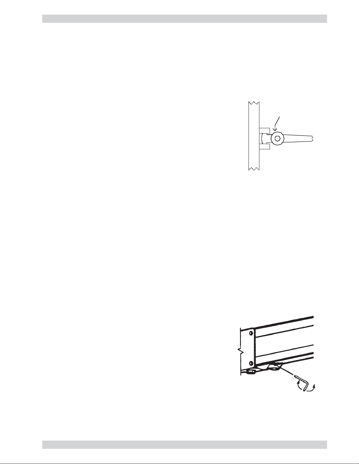
Health Care System III
Installation
Cart Adjustments
Triple-pivot Arm Counterbalance Adjustment
The following procedure applies to the optional LCD display mounting arm and the optional mobile camera
cart arm.
A nitrogen gas spring is used to counterbalance the weight of the LCD
display (or camera). To adjust the weight capacity of the arm, proceed as
follows:
Oval cap
1) Remove the oval cap by prying it off with your thumbnail.
2) Position the arm at 90 degrees with respect to the cart post.
For adjustment purposes, a 3/16” hex wrench is stored in a clip behind the
monitor’s tilt/swivel mechanism.
3) Take the 3/16” hex wrench and insert it into the hole. Turn the screw
clockwise to decrease or counterclockwise to increase the weight
capacity.
4) Remove the hex wrench and check the arm movement. Repeat the procedure if further adjustment is
necessary.
5) When adjustment is complete, re-install the oval cap on the arm and return the wrench to its storage clip
behind the monitor’s tilt/swivel mechanism.
Monitor Suspension Arm Adjustment
To adjust the suspension arm’s counterbalance, proceed as follows:
1) Lift the monitor to its uppermost position.
The counterbalance adjustment screw is accessed from the under side of the suspension arm near the monitor
mounting bracket.
For adjustment purposes, a 3/16” hex wrench is stored in a clip behind the monitor’s tilt/swivel mechanism.
2) Take the 3/16” hex wrench and insert it into the access hole. Turn
the screw clockwise to increase or counterclockwise to decrease the
counterbalance.
3) Remove the wrench and check the arm movement. Repeat the
procedure if further adjustment is necessary.
4) When finished, return the wrench to its storage clip behind the
monitor’s tilt/swivel mechanism.
27

Health Care System IIIInstallation
Operational Considerations
Iris Control and Lighting
By default the HCS III camera will use an automatic iris to compensate for changes in lighting. In addition to
this feature you may further assist the HCS III to maintain the best possible image quality by paying special
attention to environmental lighting and background colours as described below. Remember the HCS III will
send live images of yourself and your immediate surroundings.
• Avoid direct sunlight on the subject matter i.e. yourself, the background or onto the camera lens as this
will create harsh contrasts.
• If light levels are too low you may need to consider using artificial lighting. Again, avoid direct
illumination of the subject matter and camera lens.
• When using artificial lighting, ‘daylight’ type lamps will produce the most effective results. Avoid
coloured lighting.
• Indirect light from shaded sources or reflected light from pale walls, often produces excellent results.
• Avoid harsh side lighting or strong light from above, for example: strong sunlight from a window or
skylight, as this may put part or all of the subject matter in shadow or cause silhouetting.
• If you still have problems with the iris and lighting, manual adjustment of the camera parameters might
help - see the ‘Video Settings’ menu:
• If a subject is backlit, e.g. a person in front of a window, it will appear dark. This can be corrected by
switching on the backlight function (automatic on some cameras).
• Dim scenes can also be improved by manually adjusting the brightness.
Brightness Control
For adjusting brightness, colours or other adjustments of the monitor, you must use the controls monitor’s
front panel. Adjust the monitor to suit the conditions of the room. More adjustments can be made using the
on-screen menu. Refer to the monitor’s user manual for more information.
Loudspeaker Volume
The audio system uses the built-in high quality loudspeakers and amplifier specifically designed for this
system. The volume of the audio system is controlled by the volume control keys on the HCS III remote
control. The volume control on the monitor is not used.
Background
The appearance of the picture background is very important but easily overlooked. It is important to
remember that the camera also shows what’s behind you when in a videoconference. To ensure a suitable
background we recommend you consider the following:
• Use a neutral coloured background with a medium contrast and a soft texture, e.g. a plain curtain with no
heavy patterns or strong colours that may adversely tint the whole scene.
• Avoid moving backgrounds, for example: curtains in a draught, moving objects, or people walking behind
you, as this may both reduce image quality and distract the attention of the calling party.
• Do not place the camera facing a doorway.
28

Health Care System III
Installation
Guidelines for setting up videoconferencing rooms
The following are a set of guidelines to consider when either building a videoconferencing room, or using an
existing room for videoconferencing.
Lighting:
- Low Contrast desired for light intensity. No dark spots.
- Intensity @ table 800 - 1400 Lux as measured with an Incident lightmeter.
- Intensity @ back wall: minimum ˚ of that measured at table, Max ∫ of
that measured at table.
- Color temperature: Depends upon wall color and camera.
Typically 3200 - 3600 degrees Kelvin
- Block sunlight from entering room.
Seating Area (Table):
- Should allow all participants to see Monitors.
- Should allow camera to “see” all participants.
- Should allow participants to see each other.
- Should allow 3 linear feet for each participant.
- Non-shiny non-patterned preferably light grey surface (if table used).
Walls:
- Color: Depends on participants skin tones, cameras, and lighting.
Generally high contrast color desired . Light blue is commonly used.
- Acoustically reflective surfaces (such as glass or concrete) should be
covered with curtains or sound treatment.
Audio:
- Noise Floor Maximum 50dBC.
- Noise Floor preferred less than 44dBC.
- Reverb Time .3 to .5 sec.
- Absorption Coefficient .25 to .45.
- No flutter echoes.
Ventilation:
- Keep in mind Noise Floor.
- 300W (1024 BTU/HR) per person.
- 400W (1365 BTU/HR) for equipment.
- Intake and exhaust should be located near equipment.
- Velocity = Noise. Therefore keep velocity of air low.
Monitor Size:
- Optimal distance from monitor for viewing people is about 7.5 x monitor
size.
- Optimal distance from monitor for viewing documents is about 3.25 x
monitor size.
- Viewing Angle: 45 degrees off axis maximum.
Room:
- Should be located away from noise
- Should not have windows
- Doors should be located off camera - A “diamond”
shape gives best viewing angles, camera angles, and
can seat the most people.
Lighting:
Typ e Temp
Bright Daylight near equator 10 000K to 30 000K
Metal Halide Lamp 10 000K
Verilux Reptile Daylight 6 500K
Daylight White Fluorescent 6 300K
Verilux Full spectrum Fluor 6 280K
Verilux Reptile D-light 5 600K
Average Daylight 5 500K
Cool White 4 200K
Lite White 4 150K
3500K Fluorescent 3 500K
Warm White 3000-3200K
100W Light bulb 2 850K
Candlelight 1 900K
Source Intensity
Sunlight 30 000 to 100 000Lux
TV Studio 2000Lux
Average office 400Lux
By my Computer 600Lux
Moonlight 1Lux
Note: As measured with an incident light meter.
29
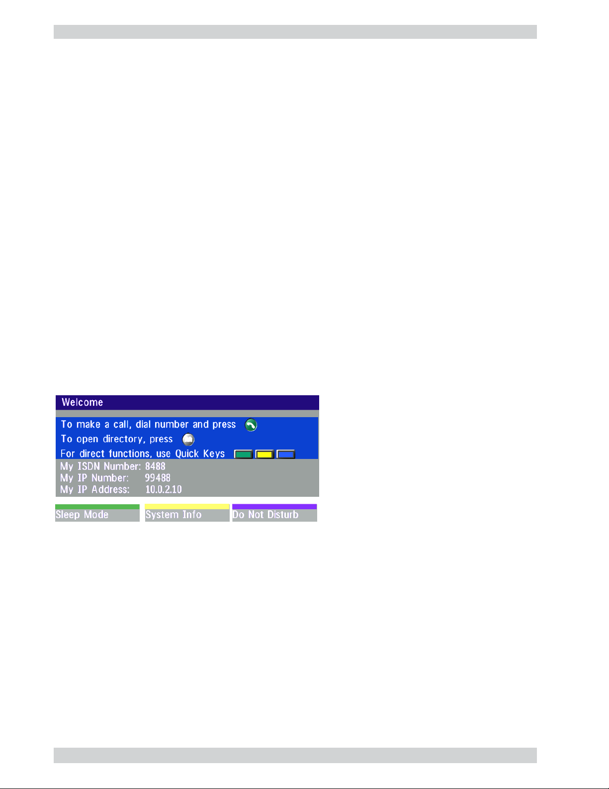
Health Care System IIIGetting Started
Getting Started
System start-up
Your system should be in standby mode. When in standby mode, pressing any key or picking up the remote
control will wake up the system. An incoming call will also wake up the system.
If the system does not respond, check that all equipment is powered on. If the equipment is not on, make sure
that the power cord of the main HCS III cart is plugged in. Switch on the monitor by pressing the power
button on the front of the monitor and ensure that line B is selected. Likewise, press the power buttons on the
optional LCD display and computer. The optional mobile camera cart is powered as long as its cable is
plugged into the rear interface panel on the main HCS III cart.
Welcome menu
After a user-definable boot-up logo is shown, the following menu is shown. This menu should provide
you with the most important system information. For further system information, select the Quick key
‘System Info’.
30

Health Care System III
Getting Started
Basics
The system’s most commonly used functions are accessible directly from the remote control by single key
presses. In addition, the user interface is represented by on-screen menus. Individual items within the menus
and lists can be selected by moving a white highlighter bar to the desired option.
Quick Keys
The three buttons on top of the remote control refer to the blocks at the bottom of
the screen. The text inside the blocks will change depending on which menu is
selected. The three Quick Keys have different colors.
P
1
vcr
+
-
u
n
e
m
t
c
e
n
n
o
c
1
4
7
*
aux doc cammain cam
move pip
mic off
OK
c
e
r
i
d
abc
P
3
P
2
Preset keys
Activate pre-stored camera positions.
snapshotpc
selfviewfar end
Video source keys
Activate connected video sources.
zoom
Camera control and menu navigation keys
Frequently used keys allowing you to control your own camera and the far end
camera, control your volume, select and move self-view, switch your
microphone off and navigate in the menu system.
t
c
e
n
n
o
c
s
i
d
y
r
o
t
Dialing keys / Preset keys
Used to make a call. The twelve number keys, (0-9), #, * operate in the same
storepresetsdelete
P
def
32
jklghi
mno
5
6
wxyztuvpqrs
9
8
#
0
way as on a modern push-button telephone. These buttons are also used when
entering a name into a text field.
31

Health Care System IIIGetting Started
Menu Structure
The on-screen menu structure is shown below.
Press the MENU key on the remote control to enter/leave the Main Menu.
Main Menu
Call Quality
Advanced
Settings
Presentations
Request Floor
Release Floor
Terminal Names
Utilities
Quick Menu
View Site #
End View
Chair Control
MCU Services
Inputs
Outputs
Echo Control
AGC Settings
Tones&Volume
Restore Audio
Defaults
Take Chair
Release
Chair
Floor to
Site #
Rel. Floor to
site #
Disconnect
Site #
Terminate
Meeting
Audio
Settings
Level Settings
Level Settings
Network Profiles
Network
LAN
Settings
Call
Settings
Data Port 1
Data Port 2
Language
Software
Options
Video
Settings
Focus
Brightness
Whitebalance
Video Name
VGA Settings
VNC Settings
ISDN-BRI
Settings
Leas. E1/T1
Settings
Ext.network
Settings
ISDN-PRI
Settings
Streaming
Settings
H.323
Settings
Adv. H.323
IP Settings
SNMP
Terminal
Settings
Diagnostics
ISDN Switch
Typ e
Line 1 Setup
Line 2 Setup
Line 3 Setup
Line 4 Setup
Line 5 Setup
Line 6 Setup
Adv. ISDN
Settings
PRI Switch
Typ e
Channel
Hunting
Line
Settings
Adv. PRI
Settings
Exit
System Info
Channel
Status
Call Status
Te st
Subsystem
System
Selftest
View Current
Settings
Restore
Defaults
32
Press U
Press O
P/DOWN/LEFT/RIGHT to navigate.
K to select.

Health Care System III
Getting Started
System configuration
• After the system has performed a self-test routine, product logo and a ‘Welcome’ menu will be displayed
on the monitor.
NOTE
THESE SETTINGS ARE ESSENTIAL
FOR OPTIMAL SYSTEM SET-UP.
• Enabled but unused ISDN lines (lines not active) should be disabled. Select the Quick Key ‘System Info’
(on the remote control) to view line status.
menu
PRESS MENU ON THE REMOTE CONTROL. SELECT THE MENU ‘TERMINAL SETTINGS’, ‘NETWORK’, ‘ISDN-BRI SETTINGS’.
SELECT THE RELEVANT ‘LINE SETUP’ MENU AND SET ‘ENABLED: OFF’.
• Enter System Name to identify the system during an MCU conference. Select ‘Utilities’, ‘System Name’
and enter the name using the number keys (as on a mobile phone).
• Select the language you want to use in ‘Terminal Settings’, ‘Language’.
• If you are using two monitors, set ‘Utilities’, ‘Dual Monitor: On’.
• To activate MultiSite and/or Presenter, enter an option key (see paperwork accompanying your system),
see ‘Terminal Settings’, ‘Software Options’.
• Press Connect on the remote control. A dial tone should be heard if the network is active.
connect
• Using the monitor remote control, adjust the volume on the monitor to a level of your choice.
This volume will be the default volume for all calls.
33

Health Care System IIIGetting Started
ISDN configuration
For each installation of the system it is necessary to configure the unit. All configuration parameters are
available via the menu system. If you are using an external IMUX or special networks, the external
equipment may also need to be configured.
• Press M
Set ‘Current Network’ to the network you want to use.
Specify the settings for the selected network in one of the menus.
For details, follow the instructions in chapter ‘Terminal Settings’, ‘Network Configuration’ in this manual.
For further information refer to the examples in:
ENU on the remote control. Select the menu ‘Terminal Settings’, then ‘Network’.
Appendix 1: Connecting the system to ISDN using NT1 network adapters
Appendix 2: Connecting the system to the Switched 56 network
LAN configuration
• Press MENU on the remote control. Select the menu ‘Terminal Settings’, then ‘LAN Settings’.
Specify the necessary LAN settings according to the instructions from your LAN administrator. If there is an
H.323 Gatekeeper present on your LAN, see also ‘H.323 Settings’.
For details, follow the instructions in chapter ‘LAN Settings’ in this manual.
34

Health Care System III
Getting Started
Making and ending calls
Making a call
connect
ISDN call
The system will, by default, try to connect using Quality: Auto (see table overleaf). If the requested quality
(bandwidth) cannot be established, the system will establish a connection on as high quality as possible.
The SoftMux ensures high reliability and includes the unique Downspeeding feature. If channels are dropped
during a meeting, Downspeeding automatically maintains the connection without interrupting the call in
progress. The SoftMux also enables you to dial to other videoconferencing equipment, phones and mobile
phones in the same way and provides you with on-screen, real-time feedback on the progress of a call.
To make a call, enter the number or the IP-address of the unit you wish to call using the Dialing
keys and press C
ONNECT.
LAN call
To make a call via a LAN, enter an IP-address by using a * as the ‘dot’ in the IP-address, e.g. 123*3*0*12
will be interpreted as 123.3.0.12. If a gatekeeper is present, you may place IP-calls using “telephone-style”
numbers (an E.164 alias), according to the numbering plan implemented in the gatekeeper. The dialed
number will then be translated into an IP-address by the gatekeeper.
Access Code
If the system requires an Access Code, enter the code and press OK to proceed making a call:
Using sub-address / extension address / MCU password
To specify an ISDN sub-address or its LAN equivalent extension address (TCS-4), add a star (*) after the
number and then enter the sub-address/extension address.
Example: 12345678*10 ( <number>*<Sub-address/extension address/MCU password>)
When calling to external MCU’s requiring a password (TSC-1), this password can be added after the star (*). If
no password is specified, a menu will prompt you to enter the password (after connected to the MCU).
TIP
SUB-ADDRESS IS USED TO ADDRESS DIFFERENT SYSTEMS ON THE SAME ISDN LINE.
TCS-4 IS USED TO ADDRESS DIFFERENT SYSTEMS ON A LAN, WHEN DIALING IN VIA A GATEWAY.
35

Health Care System IIIGetting Started
Selecting / setting default quality (bandwidth)
The default call quality setting ‘Auto’ will be used if no specific
quality is selected.
To select quality (bandwidth):
• Press the ‘Quality’ Quick Key when you are in the dial menu. The
Quality menu will then be displayed:
Type of calls
Auto 384kbps on ISDN/768kbps on LAN
Max * 768kbps on ISDN-BRI
3072 3072 kbps (3Mbps, LAN only)
2560 2560 kbps (2,5Mbps, LAN only)
1920 1920 kbps (2Mbps, 30B)
1472 1472 kbps (23B)
1152 1152 kbps (18B)
768 768 kbps (12B)
512 512 kbps (8B)
384 384 kbps (6B)
320 320 kbps (5B)
256 256 kbps (4B)
192 192 kbps (3B)
128 128 kbps (2B)(Bonding/H.221)
64 64 kbps (1B)(H.221)
H0 1xH0 (384 kbps) (PRI only)
Teleph Telephone Call
NOTE
* 1472/1920kbps (23/30Ch)
on ISDN-PRI (T1/E1)
* 3Mbps(3072kbps) on LAN
SOME SOFTWARE VERSIONS AND
NETWORKS
CHANNEL SELECTIONS.
DO NOT SUPPORT ALL
• Move the indicator to the desired bandwidth, then press the ‘Select’ Quick Key.
• You may also press the ‘Set as Default’ Quick Key in order to make the selected bandwidth the default
bandwidth for subsequent calls.
• Press ‘Set Restrict (56k)’ to make a restrict call. An indicator ‘(56k)’ will be shown behind the number.
TIP
TIP
RESTRICTED CALL
A RESTRICTED CALL IS A CALL TO A 56 KBPS NETWORK. BY DEFAULT THE SYSTEM WILL DIAL AN UNRESTRICTED CALL (A CALL TO A 64
KBPS NETWORK) AND DOWNSPEED TO 56KBPS IF NECESSARY. TO FORCE A RESTRICTED CALL, SELECT ‘SET RESTRICT (56K)’
DIALING TWO NUMBERS
SOMETIMES (ESPECIALLY WHEN CALLING TO AND WITHIN NORTH AMERICA) IT IS NECESSARY TO DIAL BOTH ISDN NUMBERS WHEN
A VIDEO CALL USING 2X64 KBPS OR 2X56 KBPS. SELECT ‘128’ IN THE QUALITY MENU. WHEN YOU RETURN TO THE DIAL
MAKING
MENU, BOTH ‘NUMBER:’ AND ‘2ND:’ ARE DISPLAYED. ENTER THE SECOND NUMBER.
36

Health Care System III
Getting Started
Selecting / setting default network
To select a specific network, press ‘Net’ when you are in the dial menu.:
• Highlight network to be used in your call.
•Press ‘Select’ to select network or press ‘Set as Default’ to set the selected network as your preferred choice
for this and all subsequent calls.
If ‘Auto’ is selected, the system will select a network based upon the following criteria:
• If an IP-address (e.g. 123*3*0*12 ) is entered, ‘LAN’ (H.323) is selected.
• If the first digits in the number are the same as set in ‘H.323 Prefix’ under ‘H.323 Settings’, ‘LAN’ is
selected.
• In other cases, ‘ISDN’ (H.320) is selected*.
If you want to assign a specific prefix to the network selection or if you want to define your own network
configuration, see ‘Network Profiles’ in ‘Call Settings’, ‘Terminal Settings’.
Answer a call
connect
End a call
To answer a call, press the CONNECT key.
Manual answer of a call is needed if the autoanswer facility is switched off. See ‘Utilities’ in
‘Advanced use’.
TIP
To end a call, press the DISCONNECT key.
ENDING A CALL
SWITCHING OFF THE MONITOR(S) WILL NOT
DISCONNECT
SHOULD PRESS THE DISCONNECT KEY.
A CALL. TO DISCONNECT A CALL YOU
Correcting keying mistakes
delete
To delete the last digit (or character) entered, press the DELETE key.
* - ISDN indicates both ISDN-BRI, ISDN-PRI, Leased E1/T1 and External Networks.
37

Health Care System IIIGetting Started
Directory
The directory is a local phone book that stores up to 100 directory entries including the last number dialed.
The entries are sorted alphabetically. The entries can be point-to-point entries or MultiSite entries (see menu
below). The MultiSite entries will not be displayed when you are in a call.
By using the dataport file system or external management systems like the TANDBERG Management Suite,
it is possible to store 200 additional entries. These entries can only be changed from the dataport or the
management system.
When the system receives an incoming call and the calling party’s number is found in the directory, the
calling party’s name will be displayed instead of the number on the status line.
Press D
IRECTORY to bring up the following menu:
TIP
WHEN LAST NUMBER DIALED IS
HIGHLIGHTED
STATES ‘STORE ENTRY’. THIS
KEY
IT POSSIBLE TO STORE LAST
MAKES
DIALED NUMBER.
To find an entry, key in the first letter, for example T, and scroll with the up/down arrows.
TIP
THE LEFT/RIGHT ARROWS WILL MOVE ONE PAGE UP/DOWN.
, THE SECOND QUICK
38
connect
To dial the selected entry press CONNECT. To edit the selected number before dialing, press OK
(only point-to-point entries).

Health Care System III
General Use
Add New Entry
When selecting ‘Add New Entry’, an empty directory entry is displayed:
1 Move to ‘Name’ and enter characters using the number keys on your remote control (as on mobile
phones). Use ‘0’ to enter ‘space’, use ‘#’ to switch between upper- and lower case.
2 Move to ‘Number’, key in the number and press OK. Specify only one number. If two numbers are
required, both numbers should be specified (2x64 or 2x56 calls).
3 Select ‘Quality’ to specify call rate to be used.
4 Select ‘Net’ to specify the network profile to be used. See ‘Selecting / setting default network’.
5 Select ‘Previous Menu’ to return to the Directory menu.
Delete Entry
When ‘Delete Entry’ is pressed, the selected entry is deleted.
Edit Entry
To edit an entry, highlight the entry you want to edit and press ‘Edit Entry’. Edit the entry and select
‘Previous Menu’ to return to the Directory menu.
Delete Entry
To delete an entry, highlight the entry and press DELETE.
39

Health Care System IIIGeneral Use
Add MultiSite Entry
When selecting ‘MultiSite Entry’, an empty MultiSite directory entry is displayed:
1 Move to ‘Name’ and enter the MultiSite meeting name.
2 Select ‘Add Site’ to add a site to the meeting by searching for point-to-point entries in the directory list.
See below for details.
3 Select ‘Quality’ to override the suggested bandwidth per site.
TIP
4 When finished, select ‘Previous Menu’.
QUALITY PER SITE: AUTO, FUNCTIONALITY
EXAMPLE: THE SYSTEM HAS MAXIMUM CAPACITY 512KBPS. TWO ENTRIES ARE ADDED, ONE WITH 384KBPS AND ONE WITH 128KBPS.
1) SINCE ALL SITES MUST USE THE SAME BANDWIDTH, QUALITY PER SITE WILL BE 128KBPS.
2) IN ADDITION, MAXIMUM BANDWIDTH PER SITE CANNOT EXCEED THE TOTAL BANDWIDTH AVAILABLE DIVIDED BY THE NUMBER OF SITES.
IN THIS CASE, THE MAXIMUM BANDWIDTH PER SITE CANNOT EXCEED 512/2=256KBPS. IF THE BANDWIDTH IN 1) IS HIGHER THAN THIS
BANDWIDTH, THE ‘QUALITY PER SITE’ SETTING MUST BE REDUCED TO CORRESPOND WITH THE TOTAL CAPACITY OF THE SYSTEM.
Add Site
Highlight the entry you want to add to the meeting and press OK. If you do not find the entry you need, select
‘Add New Entry’ to add an new point-to-point directory entry.
NOTE
GLOBAL ENTRIES WILL NOT BE AVAILABLE FOR FOR MULTISITE ENTRIES.
40

Health Care System III
General use
Adjusting volume
General Use
+
-
Press the
level.
V
OLUME
keys to adjust the volume level. An on-screen indicator will show the current
View outgoing video (selfview)
selfview
To change the image being viewed on the monitor during a call press S
shown (far end/selfview/still image or Duo Video).
move pip
Press the S
Press MOVE PIP to move your selfview as a Picture-in-Picture to different corners of the screen
or to switch it off.
ELFVIEW
key to view your outgoing video.
Microphone on/off
mic off
To mute your microphone during a call, press MIC OFF. An on screen indicator will appear when
the microphone is off. Pressing M
IC OFF one more time will activate the microphone again.
ELFVIEW
until the desired image is
TIP
MIC OFF WILL MUTE AUDIO INPUTS MIC1-3 AND AUDIO4. IT WILL NOT MUTE AUDIO FROM THE AUX AND VCR INPUTS.
Do Not Disturb / Sleep Mode
Press any Quick key when not in a call to activate the Quick Menu.
When Do Not Disturb is activated, the system will not accept any incoming calls. The caller will hear a busy
tone when calling this unit. A status line will indicate when Do Not Disturb is active.
When Sleep Mode is selected, the following quick-keys are displayed:
Pressing ‘Sleep Now’ puts the monitors in sleep mode. The system will still accept incoming calls.
Pressing ‘60 Minutes’ or ‘3 Hours’ will delay entering sleep mode accordingly.
Pressing any key or picking up the remote control will deactivate Do Not Disturb/Sleep Mode.
To see numbers, line status etc., select ‘System Info’. For further information see ‘Diagnostics’ in
‘Advanced use’.
41

Health Care System IIIGeneral Use
Controlling the Main Camera
Moving / zooming camera
To control the Main Camera use the keys below:
for pan/tilt and for zooming.
zoom
IF THE MENU SYSTEM IS ACTIVE, THE ARROW KEYS WILL NAVIGATE IN THE MENUS.
Focusing camera
The Main Camera is set for autofocus by default. If the Main Camera is moved (pan/tilt/zoom), autofocus
will be switched On automatically for 5 seconds.
To manually focus the Main Camera, see ‘Video Settings’ in ‘Advanced use’.
Selecting video sources
vcr
P r e s s : to select the video source to be transmitted to the far end.
main cam
aux
doc cam
pc
42

Health Care System III
General Use
Voice Activated Camera Positioning
Through Voice Activated Camera Positioning and the use of two or three microphones, the camera will
automatically view the speaker.
Setup
Before using camera tracking, the camera positions used must be stored at presets P7 (Mic1), P8 (Mic2) and/
or P9 (Mic3).
EXAMPLE:
THE CAMERA POSITION STORED AT P7 MUST BE RELATED TO MIC1, THEREFORE ALL PARTICIPANTS WHO ARE LOCATED CLOSEST TO MIC1
SHOULD BE INCLUDED IN THE P7 CAMERA POSITION ETC. WHEN CAMERA TRACKING IS ACTIVATED AND A PERSON CLOSE TO MIC1 SPEAKS,
P7 WILL BE AUTOMATICALLY SELECTED.
Activating
presets
Enable Camera Tracking by pressing ‘CamTrack On’ in the ‘Preset 0-9’ menu, which is
activated by pressing the P button on the remote control. An on-screen indicator ‘CamTrackOn’
P
will appear.
mic off
When activating another video source (e.g., document camera), camera tracking will be
temporarily disabled until you re-select MainCam or a MainCam preset.
Pressing M
IC OFF will temporarily disable camera tracking.
A Voice Detector makes the system more tolerent of noise and ensures the camera will not be moved by noise
such as paper shuffling, etc.
Deactivating
Disable Camera Tracking by:
• moving the camera manually.
• activating a MainCam preset when MainCam is already activated.
• disconnecting the call.
An on-screen indicator ‘CamTrackOff’ will appear.
TIP
THE CAMERA TRACKING SPEEDS MAY BE ALTERED IN THE ‘VIDEO SETTINGS’ MENU. SEE ‘ADVANCED USE’ FOR
FURTHER DETAILS.
43

Health Care System IIIGeneral Use
Presets
The preset buttons enable you to pre-store up to ten different settings. Each preset is able to store:
• Video source
• Camera position, pan/tilt/zoom/focus (if Main Camera)
• Audio source selection (see ‘Audio Settings’ in ‘Advanced use’)
Selecting presets
To select a pre-stored camera position, audio and video source, use the keys P1 P2 P3 or press P until the onscreen indicator ‘Preset 0-9’appears and use 0-9 to activate P0-P9 presets. To exit ‘Preset’ mode, press O
P
P
1
2
P
3
P1-P3 are the same presets as when pressing P and then a number key 1-3.
Storing presets
To store the current camera position, audio and video source:
K.
store
• Press STORE once and wait for the on-screen indicator to appear.
• Then press one of the keys P1 P2 P3 or a number key 0-9.
Far end camera control (FECC)
far end
Whilst activated you will be able to control the far end’s camera (pan/tilt/zoom/focus) and presets.
To control the far end camera use the keys below:
for pan/tilt and for zooming.
Far end presets can be activated by pressing the keys P1 P2 P3 or the number keys 0-9 to activate presets P0P9.
Selection of far end videosources is achieved by pressing the buttons below when in FarEndCamera mode:
main cam
Press the FAR END key until the ‘FarEndCamera’ on-screen indicator is displayed.
For this feature to operate the far end must support ‘Far end camera control’ (H.281).
zoom
aux
doc cam
vcr pc
NOTE
IF YOU PRESS DOC CAM, IT IS NOT CERTAIN THAT THE FAR END DOCUMENT CAMERA WILL BE DISPLAYED. THIS DEPENDS ON SYSTEM
CONFIGURATION AT THE FAR END.
To prevent others controlling your camera, select ‘Far End Camera Control:Off’ in ‘Utilities’.
44

Health Care System III
General Use
Sending/receiving still images
When a still image is sent, received or requested, it will be stored in the graphics memory. When a
new image is sent or received, the old image will be erased. When disconnecting the call, the image
will be erased.
Sending a still image
snapshot
• To send a still image from another video source (e.g. the document camera), select source:
main cam
• Press SNAPSHOT.
aux
doc cam
vcr
pc
snapshot
• Press S
TIP
NAPSHOT.
SEE ‘PRESENTATIONS’ MENU FOR AUTOMATIC SETUP OF THIS OPERATION.
Viewing a still image
The last sent or received still image will automatically be displayed on your screen.
• Press SELFVIEW to return to normal view.
NOTE
REQUIRES ‘AUTO-DISPLAY STILL IMAGE: ON’ IN ‘PRESENTATIONS’
Receiving a still image
A received still image will automatically be displayed on your screen.
• Press S
NOTE
ELFVIEW to return to normal view.
REQUIRES ‘AUTO-DISPLAY STILL IMAGE: ON’ IN ‘PRESENTATIONS’
Requesting a still image
• Press FAR END until the ‘FarEndCamera’ on screen indicator is displayed.
• Press S
NAPSHOT . A still image from the far end is automatically displayed.
45

Health Care System IIIGeneral Use
Duo Video *
Duo Video is useful if you want to display live video from your document camera or another camera in
addition to live video of yourself.
Add Duo Video
• Alt.1: Press any other video source than MainCam during a call. This will open Duo Video directly if the
far end supports the automatic Duo Video functionality (requires also ‘Duo Video Mode: Auto’ in
‘Presentations’).
• Alt.2: To open Duo Video (also older versions of Duo Video), press C
up the following menu:
• Select ‘Add Duo Video’. The following menu will be displayed:
• Select video source to transmit on Duo Video.
• Press C
NOTE
ONNECT to add Duo Video.
AUTOMATIC DUO VIDEO HANDLES DUO VIDEO WITHIN THE SAME CALL. IT IS NOT NECESSARY TO MAKE A NEW CALL AND THE CONNECT
DECREASES A LOT. DUO VIDEO BORROWS BANDWIDTH FROM THE MAIN CONNECTION. WHEN DUO VIDEO IS CLOSED, THE
TIME
BANDWIDTH
AN
VERSION.
IS RETURNED TO THE MAIN CONNECTION. THIS DUO VIDEO IS ALSO UNI-DIRECTIONAL AND HENCE, EASIER TO USE. WHEN IN
MULTISITE CALL, THE MULTISITE CAN TRANSMIT THIS DUO VIDEO TO THE OTHER PARTICIPANTS SUPPORTING THIS DUO VIDEO
ONNECT during a call. This will bring
NOTE
IF THE FAR END SUPPORTS DUO VIDEO, BUT NOT THE AUTOMATIC DUO VIDEO, PRESS ‘QUALITY’ TO SELECT EXTRA BANDWIDTH TO BE
USED BY DUO VIDEO. AN EXTRA CALL WILL BE MADE AND DUO VIDEO WILL NOT BORROW BANDWIDTH FROM THE MAIN CONNECTION.
* - Optional feature.
46

Health Care System III
General Use
End a Duo Video call
To end a Duo Video call, press DISCONNECT. Select if you want to disconnect only the Duo
Video connection or the whole connection.
Controlling camera, changing video source, presets in a Duo Video call
The main monitor will always display incoming video. The 2nd monitor will display outgoing video (Duo
Video in full screen / Main connection in PIP).
Pressing S
ELFVIEW will toggle Duo Video full screen / Main source in PIP and vice versa. Pressing SELFVIEW
will not change anything on the main monitor.
Pressing M
OVE PIP will move PIP only on the 2nd monitor.
Controlling the camera, changing video source, using presets will affect the video source currently displayed
in full screen mode.
EXAMPLE IF DUO VIDEO IS SHOWN IN FULL SCREEN ON THE 2ND MONITOR, PRESSING ANY OF THE VIDEO SOURCE BUTTONS WILL CHANGE
DUO VIDEO SOURCE. IF THE MAIN CONNECTION IS SHOWN IN FULL SCREEN, PRESSING ANY OF THE VIDEO SOURCE BUTTONS WILL CHANGE
THE MAIN CONNECTION SOURCE.
If both connections are selected to display the same video source, Duo Video will be closed.
47

Health Care System IIIGeneral Use
MultiSite (MCU)*
The system has a built-in multipoint conference unit (MCU), MultiSite, which has the capability to establish
meetings with up to 4 video sites (5 if at least one site is a telephone call, ISDN/analogue/mobile).
The video calls in a conference must be connected using the same bandwidth.
A conference can consist of any combination
of ISDN/LAN sites.
It is possible to have telephone meetings
with up to 5 participants.
The MultiSite supports both Voice Switched
and Continuous Presence mode (see ‘MCU
Services’ in ‘Advanced use’ for description
of these modes).
Establishing a conference is done by first
making a call to one site. When a call is
established with the first site, the other sites
are connected one by one.
It is possible to either dial out to the sites or
the sites can dial in to the MultiSite.
TIP
ULTISITE - WHICH QUALITY CAN BE USED ON EACH SITE?
M
4 SITES 4 SITES 3 SITES 3 SITES + P-TO-P +
(2MBPS VERSION)+ 1 PHONE 1-2 PHONES 1-3 PHONES
BRI (768 KBPS) 256 KBPS 192 384 320 512
PRI-E1(1920 K) 512 512 768 768 1472
PRI-T1(1472 K) 384 384 512 512 1152
LAN/MIX (2304 K) 768 768 * 1152 1152 * 1920 *
MIX ISDN/LAN EXAMPLE: IF 4 SITES ARE CONNECTED, TWO LAN SITES AND ONE ISDN SITE CAN BE CONNECTED ON 512 KBPS (2MBPS VERSION)
OR 256 KBPS (768 KBPS VERSION). NOTE - 4 SITES INDICATES YOURSELF + THREE OTHER SITES.
* - REQUIRES 1-3 ISDN CHANNELS AVAI L AB L E .
SEE ‘UTILITIES’, ‘CONTINUOUS PRESENCE’ TO CHANGE
MODE.
NOTE
WHEN MIXING
ISDN AND LAN
SITES, THE TOTAL
BANDWIDTH
LIMATATION
THE
THE
BANDWIDTH.
IS
SAME AS FOR
ISDN
* - Optional feature.
48

Health Care System III
General Use
MultiSite cascading
By connecting four MultiSite systems together, it is possible to connect up to 10 video sites (including the
four MultiSite sites) plus 4 audio sites (telephones), see drawing below.
The host can connect up to 3 other video systems with MultiSite functionality. The host can use Voice
Switched or Continuous Presence mode.
The cascaded systems connect to two other video sites plus one audio site each. These systems will
automatically run Voice Switched mode and transmit a full screen image to the host when calling on ISDN.
When calling on IP, Voice Switched Mode must be selected manually.
NOTE
ALL CONNECTIONS CAN BE ANY
COMBINATION OF ISDN/IP.
Establishing MultiSite meetings using Directory
It is possible to pre-define meetings using Directory. All sites will then be connected automatically instead of
having to add one by one site.
• Press D
• Highlight a MultiSite entry and press C
IRECTORY.
ONNECT.
See ‘Directory’ section for further information.
49

Health Care System IIIGeneral Use
Adding an extra site - dial out
First establish a normal point-to-point call. It is recommended to plan the bandwidth usage before making the
first call so that you do not run out of bandwidth.
Example: If the system has 512kbps available and you want to connect 3 sites in addition to the host,
128kbps should be selected for the first call. The system will then automatically use 128kbps when
connecting the other sites.
When the first site is connected, add a site to the conference using the following procedure:
connect
• Press ‘Add Site’ to bring up the MultiSite dial menu.
• Press CONNECT to bring up the following menu:
NOTE
TIP
IF THE MULTISITE SYSTEM DOES NOT HAVE
BANDWIDTH TO ADD ANOTHER SITE,
ENOUGH
THE SYSTEM WILL AUTOMATICALLY DOWNSPEED
ALLOW AN ADDITIONAL SITE TO BE ADDED TO
TO
CONFERENCE. REQUIREMENT: FAR END
THE
SUPPORT DOWNSPEED AND MUST HAVE
MUST
ENOUGH BANDWIDTH.
CONNECT THE SYSTEM WITH THE LOWEST
BANDWIDTH
CONNECTION TIME.
FIRST IN ORDER TO OPTIMIZE
• Enter the number to call.
The Quality will, by default, be the same as used by the first call. To place a telephone call instead of a video
call, press ‘Quality’ and select ‘Te le ph ’ in the Quality menu.
To use another network operator, press ‘Net’ and select operator in the Net menu.
connect
• Press C
ONNECT
TIP
50
IT IS POSSIBLE TO CONNECT SEVERAL TELEPHONES, E.G. 2 VIDEO SYSTEMS + 3 TELEPHONES (A TOTAL OF 5 SITES).

Health Care System III
General Use
Adding an extra site - dial in
To dial in to the MultiSite on ISDN-BRI:
TIP
• Site 2 must dial MultiSite Number 2.
• Site 3 must dial MultiSite Number 3.
To dial in to the MultiSite on ISDN-PRI:
• Dial the main number of the system (‘My ISDN Number’). All sites can dial the same number.
To dial in to the MultiSite on IP:
• Dial the IP Number or the IP Address of the system (‘My IP Number’/‘My IP Address’).
When the MultiSite receives an incoming call, the following menu is displayed:
TO FIND THE DIAL-IN NUMBERS FOR THE
MULTISITE, PRESS ‘MENU’ AND ‘SYSTEM
INFO’
• Pressing C
• Pressing D
ONNECT is equivalent to pressing ‘Accept’.
ISCONNECT is equivalent to pressing ‘Reject’.
• Pressing ‘Do Not Disturb’ will disable the MultiSite from answering more incoming calls during the
current conference. The calling party will receive a busy signal.
Disconnecting sites from a conference
disconnect
To end the meeting press ‘Disconnect All’.
To disconnect a site or end the conference, press DISCONNECT.
• Select site and press OK or ‘Disconnect Site’.
NOTE
EACH SYSTEM WILL BE IDENTIFIED BY
SYSTEM NAME (IF SUPPORTED) AND
A
THE NUMBER OF THE FAR END.
51

Health Care System IIIGeneral Use
PC Presenter
Plugging a PC into the system is made extremely simple through the PC Presenter, avoiding the need for any
additional hardware such as a projector, PC/Video converter or extra cables.
• Start your PC.
• Press P
• Press S
C on your remote control.
ELFVIEW until the indicator ‘Selfview‘ is displayed on your main monitor (single monitor system)
or until you see the PC image on the second monitor.
If no PC image is displayed on your monitor, make sure that your PC transmits the image to the VGA
Output, and that the PC transmits a supported VGA-format (see tip below). Consult your PC-operating
manual to see how to transmit a VGA image from your PC (typically: Fn+F5).
VGA-FORMATS SUPPORTED (VESA COMPLIANT)
·640X480 60,72,75,85 HZ
·800X600 56,60,72,75,85 HZ
·1024X768 60,70,75 HZ
PC SoftPresenter *
PC SoftPresenter is used to display PC images on your system. The system and your PC must be
connected to a LAN. In addition, VNC (Virtual Network Computing) server software must be installed on
the PC.
To show the PC image:
• Start the VNC software on your PC.
• Press P
C on your remote control. Use UP/DOWN to activate PAGE UP/PAGE DOWN on the PC.
For setup information and details, see ‘VNC Settings’ in ‘Advanced use’.
NOTE
‘PC: VNC’ MUST BE SET IN ‘VIDEO
SETTINGS’.
* - Optional feature.
52

Health Care System III
General Use
Web-interface
It is possible to access and maintain the system remotely via a local area network (LAN) using a standard
Web-browser.
Connect your system to a local area network.
LAN Port
Rear Interface Panel
LAN Port
Local Area Network
LAN
Configure your codec:
• Press MENU, select ‘Terminal Settings’, ‘LAN Settings’
• Specify IP-assignment ‘DHCP’ or ‘Static’. If DHCP is selected no other settings are needed. If Static is
selected, ‘IP-address’, ‘IP-subnet mask’ and ‘Gateway’ must be specified.
Example:
IP-assignment: Static
IP-address: 196.9.200.129
IP-subnet mask: 255.255.255.0
Gateway: 196.9.200.21
NOTE
THE SYSTEM MUST BE RESTARTED BEFORE CHANGES IN THE
‘LAN SETTINGS’ MENU CAN TAKE EFFECT.
See ‘LAN Settings’ in ‘Advanced use’ for further information.
• Start your Web-browser. In the address field type the IP-address of the codec. The Web-page of the codec
will be shown.
Text Chat / Closed Captioning
While in an ISDN or IP call to another system supporting Text Chat (T.140), select ‘Text Chat’ from the
Web-page of the codec. Enter text in the window displayed. When selecting ‘Send Text’, the text will be
displayed on the local and far-end monitor as shown below:
The local Text Chat window can be closed manually from the Web-interface by pressing ‘Close Window’ or
it will close automatically after a few minutes without activity.
53

Health Care System IIIGeneral Use
Streaming
To view streaming, select ‘Streaming’ from the Web-page of the codec. See separate ‘Streaming’ section in
this manual for further information.
T.120 and other PC applications
A PC can be connected to the system using a serial cable. This will enable interactive editing, file transfer
and application sharing between two computers.
Appropriate communication software should be used (for example: Microsoft NetMeeting, Intel ProShare
Premier, Windows HyperTerminal, Procomm Plus and so forth.)
The system has been specially designed to work with interactive programs and includes a data channel that
can send and receive data to and from the far end at speeds of up to 38,400 baud.
54

Health Care System III
Advanced use
Main menu
The menu system can be used to select available functions and utilities for the system.
Advanced Use
menu
To enter the menu system and the main menu, press the MENU key. You may leave the menu
system at any time by pressing the M
ENU key.
TIP
NOTE
A MENU STRUCTURE MAP IS PROVIDED IN THE
‘MENU STRUCTURE’ AT THE FRONT OF
SECTION
THIS MANUAL.
IN THE FOLLOWING MENU DIAGRAMS THE
DEFAULT SETTINGS ARE HIGHLIGHTED.
To navigate through the menu system, use the cursor keys to move the highlighted bar
to the desired sub-menu or choice.
To confirm a highlighted selection, press O
K.
To return to the previous page, press the * key or select ‘Previous Menu’.
Select ‘Call Status’ to view technical information regarding the current call.
Select ‘ System Info’ to view system numbers, line status, software version and other useful information.
55

Health Care System IIIAdvanced Use
Call quality
The Call Quality menu allows you to select the preferred quality of your call.
NOTE
Audio
DUE TO ACTIONS OR LIMITATIONS AT THE FA R END YOU MAY NOT ALWAYS BE ABLE TO ACHIEVE THE SELECTIONS YOU WANT.
TIP
AUTO
1-4 CHANNELS: G722.1 IS SELECTED.
5 -30 CHANNELS: G722 IS SELECTED.
Auto Optimized audio quality depending on bandwidth.
High High audio quality (G722) regardless of bandwidth.
Normal Telephone quality (G728) regardless of bandwidth.
Video*
Auto Will select ‘Motion’ or ‘Sharpness’ depending on selected video source**.
Motion Optimized for smooth motion video for all video inputs.
Sharpness Optimized for sharp video for all video inputs.
Natural Video
Auto Interlaced video capabilities (ICIF) will be transmitted and enabled.
Off Interlaced capabilities will not be transmitted. Useful if far end can not handle these capabilities.
VGA Resolutions
Auto VGA capabilities (VGA/SVGA) and SIF capabilities will be transmitted and enabled.
Off VGA capabilities will not be transmitted. Useful if far end can not handle these capabilities.
TIP
SIF CAPABILITIES WILL ENABLE BETTER VIDEO QUALITY FOR NTSC SYSTEMS (SIF: 352X240, ISIF: 352X480, 4SIF: 704X480).
* - If option ‘Presenter’ is not installed or if H263 is not used, only CIF resolution will be used for all selections.
** - MainCam/Aux/VCR will select ‘Motion’. DocCam/PC will select ‘Sharpness’.
56

Advanced call quality
Health Care System III
Advanced Use
NOTE
THE SELECTIONS MADE IN THIS MENU WILL OVERRIDE THE SELECTIONS MADE IN THE ‘CALL QUALITY’ MENU.
IF ‘AUTO’ IS SELECTED, THE SETTINGS IN ‘CALL QUALITY’ WILL BE USED.
Audio
Auto The setting of ‘Audio: Auto/High/Normal’ in ‘Call Quality’ will be used.
G.722.1 Compressed high quality audio (7 kHz).
G.722 High quality audio (7 kHz).
G.728 Compressed normal quality audio (telephone quality, 3.1 kHz).
G.711 Normal quality audio (telephone quality, 3.1 kHz).
Off No audio is transmitted.
Video
Auto Optimized video quality depending on
available bandwidth.
H.263 Bandwidth efficient video compression
and decompression.
H.261 Normal video compression and decompression.
Off No video is transmitted.
TIP
RESOLUTION, AUTO FUNCTIONALITY
(IF SUPPORTED BY FAR END):
WHEN ‘VIDEO: MOTION’ :
LOW BANDWIDTHS: CIF, SIF
HIGH BANDWIDTHS: ICIF,ISIF
WHEN ‘VIDEO: SHARPNESS’ :
4CIF, 4SIF, VGA, SVGA
Resolution
Auto The setting of ‘Video: Auto/Motion/Sharpness’ in ‘Call Quality’ will be used, see
tip above.
4CIF * Digital Clarity (704 x 576 pixels), only for H263.
iCIF Natural Video (352 x 576 pixels for PAL, 352x480 pixels for NTSC), only for H263.
CIF High resolution video (352 x 288 pixels).
QCIF Low resolution video (176 x 144 pixels)
H.331
Off Standard two-way communication with quality negotiation between both sides.
On Used when broadcasting a video conference from one site to many others, e.g. via
satellite, where there is no possibility to negotiate quality between the receivers
and the originator due to one-way communication.
Status Format
Provides call quality feedback on the status line.
Auto Video off/on, Audio off/normal/high
Advanced Shows video/audio standards (Example: Video: H261 CIF, Audio: G722).
* - Requires option ‘Presenter’. To check which options are installed, see the ‘System Info’ menu in ‘Diagnostics’.
57

Health Care System IIIAdvanced Use
Presentations
Presentation Mode
To send a still image immediately after pressing SNAPSHOT select ‘Presentation Mode: Normal’.
To preview the image before it is transferred as a still image, select ‘Presentation Mode: Preview’. When
pressing S
it as a still image by pressing S
Duo Video Quality *
Auto: Optimized video depending on selected video source and bandwidth in use**.
NAPSHOT you will be allowed to view your still image, e.g. from the document camera, before sending
NAPSHOT again. The far end will not see the still image while you are adjusting it.
Motion: Duo Video is optimized for smooth motion video. This mode is ideal if the image from two
W.A.V.E. cameras should be simultanously transmitted to the far end.
Sharpness: Duo Video is optimized for sharp video, Digital Clarity. This mode is ideal when using a document
camera or a PC on Duo Video. If the far end does not support 4CIF live video, CIF will be selected.
Duo Video Mode *
Auto: Pressing any video source during a call will automatically open Duo Video (if the far end supports
the automatic Duo Video functionality).
Manual: Duo Video must be opened by pressing C
ONNECT during a call and selecting ‘Add Duo Video’.
Duo Video Number***
Auto: When adding Duo Video in a conference, Duo Video is connected automatically if supported by the far end.
Manual: When adding Duo Video in a conference and connected towards a system with no Duo Video capabilities,
enter the Duo Video Number into the ‘Number’ field in the ‘Add Duo Video’ menu. This can be the number
to another system (only video will be transmitted to the system receiving Duo Video).
Duo Video / Still Image source
Select which video source Duo Video transmits.
If you want the document camera to be the default source when using Duo Video / still images, select ‘Duo
Video / Still Image source: DocCam’.
To use the same video source as on the first connection for Duo Video / still images, select ‘Duo Video / Still
image source: Current’.
* - Requires option ‘Presenter’ and H263 video. To check which options are installed, see the ‘System Info’ menu in ‘Diagnostics’.
** - 4CIF: PC and DocCam, otherwise CIF.
*** - Requires option ‘Presenter’. To check which options are installed, see the ‘System Info’ menu in ‘Diagnostics’.
58

Health Care System III
Advanced Use
Auto-display still image
Select On to automatically display a received still image. If this selection is Off, you will have to press
ELFVIEW to display a still image.
S
Still image filter
Select On to remove any instability in the high quality still image.
Utilities
Autoanswer
On: The system will automatically answer all incoming calls.
On+MicOff: The system will automatically answer all incoming calls and switch the microphone off
when the call is connected. Press M
Off: You must manually answer all incoming calls by pressing the CONNECT key.
ICOFF to switch the microphone on.
Far end camera control
On: The far end will be able to:
• Control your camera
• Select your video sources
• Activate your presets
• Request still images
Off: None of the four features above on the local system can be accessed by the far end, however
still be able to control the camera on the far end.
you will
Dual Monitor
On: Selfview, still images and Duo Video will be displayed on the 2nd monitor.
Off: The 2nd monitor shows Selfview only.
Auto-PIP
On: Your selfview will automatically be displayed (as a Picture-in-picture) whenever the camera position or
video source is changed. Picking up the remote control will also display your selfview.
59

Health Care System IIIAdvanced Use
Welcome Menu
The Welcome menu can be shown when the system is not in use, and when sleep-mode is not activated.
On: The Welcome Menu is shown when the system is not in sleep mode.
Off: The Welcome Menu is not shown.
Continuous Presence
On: The screen is divided into three or four squares, each displaying the video image of a different
participant.
Off: The active site will be displayed in full screen during a MultiSite conference. Also called Voice
Switched mode.
TIP
TO DISPLAY YOUR SITE IN FULL SCREEN WHEN ‘ON’ IS SELECTED, PRESS THE QUICK KEY ‘REQUEST FLOOR’.
MCU status line
On: The MultiSite/MCU/DuoVideo indicators will be displayed and provide information about the
conference.
Off: The MultiSite/MCU/DuoVideo indicators will not be displayed.
Auto: The MultiSite/MCU/DuoVideo indicators will be displayed for a few seconds and then timed out.
When grabbing the remote control, the indicators will be shown again.
60

Health Care System III
Advanced Use
System Name
Identifies the system:
• during an MCU conference call.
• when using the Web-interface.
• when the codec is acting as an SNMP Agent.
• towards a DHCP server.
• as an H323 ID. Other systems can call us using this name instead of IP-number/IP-address.
MCU services
A Multipoint Control Unit (MCU) enables several sites to participate in the same conference.
An MCU conference can have different modes:
Voice Switched means that the image of the person currently speaking will be broadcast to all the other
conference participants. This will remain the case until another participant starts to speak.
Continous Presence shows several participants on the same screen at the same time.
Chairman Control functionality enables one participant to control the meeting by selecting which of the
conference participants is to be broadcast to the other participants.
NOTE
THIS SYSTEM HAS AS AN OPTIONAL BUILT-IN MCU, MULTISITE, WHICH SUPPORTS UP TO 3 VIDEO CALLS (4 SITES) AND ONE TELEPHONE
CALL. THE MULTISITE SUPPORTS BOTH VOICE SWITCHED AND CONTINUOUS PRESENCE MODE, SEE SECTION ‘MULTISITE’.
The system can also control external MCUs in a very flexible manner using the functions described below.
TIP
DURING AN MCU CONFERENCE, A STATUS LINE WILL PROVIDE INFORMATION ABOUT THE CONFERENCE. TO REMOVE THIS STATUS LINE,
SELECT ‘UTILITIES’, ‘MCU STATU S LINE: OFF’.
61

Quick Menu
When connected to an MCU
Health Care System IIIAdvanced Use
TIP
PRESS ANY QUICK KEY WHEN IN A MULTIPOINT CONFERENCE TO ACTIVATE THE QUICK MENU.
This menu provides access to the most commonly used MCU functions.
If ‘ Request Floor’ is selected, ‘Request Floor’ will change to ‘Release Floor’.
If ‘ View Site#’ is selected, ‘View Site #’ will change to ‘End View’.
Selecting ‘Take Chair’ will send a request to take chair. If granted, the Quick keys will be:
If ‘Floor to Site#’ is selected, ‘Floor to Site#’ will change to ‘Rel. Floor To Site’.
If ‘Release Chair’ is selected, you will return to the original Quick menu.
When MultiSite
If ‘Voice Switched’ is selected, ‘Voice Switched’ will change to ‘Cont. Presence’. This setting can also be
changed in the ‘Utilities’ menu.
Request floor
When requesting the floor, the MCU will broadcast your video in full screen to all other participants in the
conference. If the MCU conference has a chairman, a floor request is sent to the chairman..
You will remain ‘On Air’ until either you select ‘Release Floor’ or the chairman decides to release the floor
to another participant.
Release floor
You choose ‘Release Floor’ to take you ‘Off Air’. You should do this when you wish to make the floor
available to the other participants in the conference.
Terminal Names
Allows you to see the site numbers or name (if supported) of other sites connected in the conference.
View site # *
Allows you to view any participant in the conference other than the participant currently ‘On Air’.
End view
Allows you to stop viewing the site previously chosen with ‘View Site #’, and returns your view to the site
that is currently ‘On Air’.
TIP
62
‘VIEW SITE’ AND ‘END VIEW’ CAN BE USED BY ALL CONFERENCE PARTICIPANTS.

Chair control *
Health Care System III
Advanced Use
TIP
IN ORDER TO MAKE USE OF CHAIR CONTROL FEATURES THE
MCU MUST SUPPORT CHAIR CONTROL (H.243).
You select ‘Chair Control’ and ‘Take Chair’ to assume the role of chairman of the ‘meeting’. As chairman,
you may control which site you and the other sites see.
Take chair
Allows you to request chairmanship of the conference. If no one else is currently chairman the MCU will
give you the chair.
Release chair
Allows you to relinquish the privileges of chairmanship of the conference.
Floor to site #
Allows the chairman to select which of the conference participants is to be broadcast to all other participants.
Release Floor To Site
Allows the chairman to release the floor.
Disconnect site #
Allows the chairman to disconnect any participant in the conference.
Terminate meeting
Allows the chairman to terminate the conference altogether.
* - NOT supported by the MultiSite
63

Audio Settings
Audio Inputs
Health Care System IIIAdvanced Use
By default, all inputs are enabled. Just plug in an audio source and it is active. Audio inputs that are On will
automatically be mixed. Select Off to prevent audio/noise from unused inputs or if you want to disable a
specific input. The activated audio sources are stored on presets.
Mic 1,2 and 3 are intended for electret type microphones. The microphone inputs are balanced with 24V
phantom power.
Audio input 4 is intended for connection to an external microphone amplifier or an external fixed mixer.
NOTE
EXTERNAL MIXER
WHEN USING AN EXTERNAL MIXER, IT IS VERY IMPORTANT THAT THIS IS A FIXED MIXER. AUTOMATIC, SMART AND OTHER TYPES OF
ADAPTIVE MIXERS MIGHT CAUSE THE ECHO CANCELLER TO MALFUNCTION.
Audio input 5 is intended for connection to external playback devices or to telephone add-on hybrids.
As there is no acoustic echo canceller on this input it should not be connected to any microphones. The audio
entering this input will be heard from the local speaker.
Audio input 6 is intended for connection to a VCR. It can also be connected to other external playback
devices. As there is no acoustic echo canceller on this input it should not be connected to any microphones.
The audio entering this input will be heard from the local speaker.
Mix Mode
‘Auto’ automatically adjusts the weighting of each microphone to obtain the best possible audio and
minimizes the background noise. ‘Auto’ will also attenuate the VCR audio when someone talks into a
microphone. ‘Fixed’ will maintain a constant weighting of all microphones.
64

Health Care System III
Advanced Use
Level Settings
Adjust the audio input levels according to which external audio equipment is connected. The on-screen audio
level indicator will make it easier to set the correct input level settings. The input level should be adjusted so
that the average level reaches the preferred level marker. The audio inputs are adjustable in steps of 1.5 dB
from 0 dB to 22.5 dB.
The default levels for Mic 1,2 and 3 are set for use with an Audio Technica AT871 microphone in an average
videoconferencing room. The gain can be adjusted correctly for a wide range of microphones.
A few examples of microphone levels are:
Audio Technica AT871 +3dB (default with system)
Audio Technica AT851R +7dB
TANDBERG Audio Science +19.5dB
Audio 4, 5 and 6 are set to a default level which is adhered to by most manufacturers of audio-visual
equipment and is a level at which most audio-visual equipment (CD-players, VCRs) will work.
Audio Outputs
Audio out 1 is intended for connection to TANDBERG Natural Audio, televisions or audio amplifiers.
Audio out 2 is intended for connection to audio recording equipment or to a telephone add-on hybrid. The
signal is a mix of audio from both the far end and local end (not from Audio in 5).
Audio out 3 is intended for connection to a VCR or other recording equipment. The signal is a mix of audio
from far end and local end (not from Audio in 6).
Audio Module: Select Natural Audio Module according to the type of Audio Module installed.
NOTE
NEVER CONNECT AUDIO OUT 2 OR AUDIO OUT 3 TO A LOUDSPEAKER PLACED IN THE SAME ROOM AS THE MICROPHONES CONNECTED TO THE
SYSTEM. DOING THIS WILL CAUSE “HOWLING” AND POSSIBLE DAMAGE TO THE SPEAKER SYSTEM.
If an output is ‘Off’, no audio will be sent to that output.
65

Health Care System IIIAdvanced Use
Level Settings - Outputs
Adjust the audio output levels according to the parameters of the external audio equipment connected. These
levels should only be adjusted when installing new audio equipment. The default settings are correct for the
TANDBERG Natural Audio module and for most consumer electronics devices (televisions, VCRs, etc.).
The volume keys on the remote control adjust the level of output 1 (the speaker output). The volume control
has no effect on outputs 2 and 3.
Echo Control
Each of the 3 microphone inputs and Audio input 4 have a separate echo canceller.
One echo canceller per
input provides more sophisticated control than having one common canceller for all microphones.
Echo control is normally set to ‘On’ to prevent the far end from hearing their own audio. Once selected, echo
cancellation is active at all times. The echo canceller continously adjusts itself to the audio characteristics of the
room and compensates for any changes it detects in the audio environment. If the changes in the audio conditions are
very significant the echo canceller may take a second or two to re-adjust.
You can choose to switch off the echo canceller for the available audio sources.
NOTE
ECHO CONTROL SHOULD BE SWITCHED ‘OFF’ IF EXTERNAL ECHO CANCELLATION OR PLAYBACK EQUIPMENT IS USED. IT IS YOUR ECHO
CANCELLER
MOST LIKELY THE FA R END’S ECHO CANCELLER THAT IS MALFUNCTIONING.
THAT IMPROVES THE AUDIO QUALITY EXPERIENCED BY THE OTHER SITE. WHEN YOU HEAR AN ECHO OF YOUR OWN AUDIO IT IS
Noise Reduction
In addition to echo cancellation, the system has built-in noise reduction (NR).
NR reduces constant background noise (e.g. noise from air-conditioning systems, cooling fans etc.). In
addition, a highpass filter (Humfilter) reduces very low frequency noise.
Choose On+NR to activate both Echo Control and Noise Reduction.
66

Health Care System III
Advanced Use
Room Size
This setting allows optimization of the echo canceller to the acoustic size of the room. Hard walls, many
windows etc. might require higher settings than expected. Carpets, curtains etc. might require lower settings.
Adjust the setting (NOTE: on the far end) if one of the following symptoms occur:
• There is still some echo of your own audio. Increase the setting.
• The system adapts slowly to acoustic changes in the room. Decrease the setting.
After a change, the system will need a few seconds to re-adjust.
Motion
If you experience echo caused by movements in the room, increase the value.
Automatic Gain Control (AGC) Settings
Select ‘On’ to allow automatic adjustments (Automatic Gain Control) of audio levels. When ‘On’, the AGC
maintains the audio signal level at a fixed value by attenuating strong signals and amplifying weak signals.
Very weak signals, i.e. noise alone, will not be amplified.
Example: In most conferences, the participants will speak at different levels, and be at different distances
from the microphones. As a result, some of the participants will be harder to hear than others. The AGC
corrects this problem by automatically increasing the microphone levels when “quiet” or “distant” people
speak, and by decreasing the microphone levels when “louder” people speak.
NOTE
TO ENSURE CORRECT BEHAVIOUR OF THE AGC, IT IS CRUCIAL THAT THE LEVELS ON THE INPUT CONNECTORS ARE ADJUSTED CORRECTLY
USING THE AUDIO INPUT LEVEL SETTINGS. THE AGC WILL NOT COMPENSATE FOR SEVERE MISADJUSTMENT OF INPUT LEVELS.
When applying a weak signal in the presence of strong background noise, the leveller might amplify the
background noise as well as the signal. Therefore, in noisy environments, it is advisable to turn the leveller
off.
67

Health Care System IIIAdvanced Use
Tips for improving the echo canceller performance:
• Place all microphones as far as possible from the loudspeaker. Minimum loudspeaker-microphone
distance should be 1 meter.
• Place all microphones as close as possible to the persons speaking. By using several microphones, the
ratio distance loudspeaker-to-mic/mic-to-speaker can be increased. Increasing this ratio improves the echo
canceller performance. Avoid distances above two meters from any participant to his/her closest
microphone. If necessary, use several microphones. Also avoid placing microphones less than one meter
from any person.
• Place all microphones as far as possible from noise sources.
• Reduce the volume setting. Ensure that the loudspeaker does not distort the audio.
• The echo canceller tries to estimate the echo path from the speaker system to the microphones. Moving
objects change this path, therefore try to avoid moving objects. Be especially aware of large objects and
objects placed close to either the microphone or the speaker system as these objects will cause severe
changes to the echo path.
• Avoid putting paper sheets etc. on the microphone.
• Avoid moving the microphone or loudspeaker.
• In the event of poor echo cancelling, allow the canceller to adapt. After each change, the echo canceller
requires a few seconds to adapt. Do not change the settings etc. without allowing the canceller to adapt to
the new audio environment.
• In the presence of low frequency noise, enable the noise reduction (NR).
Alert Tones & Volume
To help distinguish between incoming video calls and ordinary telephone calls, different ringing tones may
be selected. You may also select different volume levels for the ringing tone.
Alert Speaker
The system also has an internal, call alerting speaker.
On: The internal speaker will warn you of an incoming call even though the monitor may not be switched on.
Restore Audio Defaults
There are many audio settings. It is easy for the user to configure the codec to be unusable. Therefore it is
possible to set all audio settings back to default settings by using Restore Audio Defaults.
68

Video Settings
Health Care System III
Advanced Use
NOTE
THE CAMERA TRACKING MODE
WILL BE GREYED OUT IF NOT
ENTRY
USING THE WAVE CAMERA.
Camera Tracking Mode
Select the camera tracking mode:
Slow: The system waits a while before zooming in on a single person speaking. Suitable when wide-angle
images are preferred over close-up images.
Norm: Should be used in regular meetings.
Fast: The system quickly zooms in on a single person speaking. Suitable when close-ups are preferred over
wide-angle images.
Document Camera
Users of a document camera with S-video output can configure the system to activate an S-video input when
pressing ‘doc cam’ on the remote control.
Video2: Video Input 2 (S-video) will be activated when pressing ‘doc cam’ on the remote control.
Video3: Video Input 3 (Composite) will be activated when pressing ‘doc cam’ on the remote control.
PC
Configure what should be activated when pressing PC.
VGA: Pressing PC will activate the VGA input on the system (default).
VNC: Pressing P
C will use VNC to show images from your PC (see ‘VNC Settings’ for further information).
Focus
To manually adjust the focus select ‘Manual’ and use the arrow keys to adjust.
Brightness
To manually adjust the brightness select ‘Manual’ and use the arrow keys to adjust.
Whitebalance
In Auto mode the whitebalance is continuously updated. To update the whitebalance manually, select
‘Manual’ and press OK.
TIP
A WHITE OBJECT SHOULD BE HELD IN FRONT OF THE CAMERA A FEW SECONDS BEFORE AND AFTER SELECTING MANUAL WHITEBALANCE.
69

Health Care System IIIAdvanced Use
Video Name
Each video input defaults to the same name used on the remote control to select a video input.
To edit the name, use the number keys on the remote control to select letters. Press D
VGA Settings
NOTE
NOTE
IF YOU SET ‘VGA OUT’ TO ‘MAIN’,
MAKE SURE YOU HAVE A VGA-MONITOR
CONNECTED
THE
MONITOR CONNECTED, YOU WILL NOT BE
ABLE TO SEE THE MENU SYSTEM!
ICIF WILL NOT BE AVAILABLE WHEN
VGA OUT IS MAIN OR DUAL.
ELETE to erase a letter.
TO THE VGA-OUTPUT ON
SYSTEM. IF YOU NOT HAVE A VGA-
VGA Out
To enhance the local video quality, a VGA monitor may be connected.
Main: Should be used if you want to use a VGA monitor as your main monitor. Video output 1&3 will
be disabled.
Dual: Should be used if you want to use a VGA monitor as your dual monitor. Video output 2&4
will be disabled.
Loop: ‘VGA Out’ will display whatever is present on ‘VGA In’. All video outputs will be enabled. The
VGA monitor will act as a third monitor.
VGA Out Quality
VGA Out Quality changes the resolution of the VGA signal available on the ‘VGA Out’ connector at the rear
of the codec.
NOTE
THE HCS III SHOULD HAVE THE ‘VGA
OUT’ SET TO DUAL, AND ‘VGA OUT
QUALITY’ SET TO SVGA FOR BETTER
PICTURE QUALITY.
70

VNC Settings
Health Care System III
Advanced Use
NOTE
VNC SERVER SOFTWARE SETUP
• BOTH THE PC AND THE VIDEOCONFERENCING SYSTEM MUST BE CONNECTED TO THE LAN.
• A VNC SERVER MUST BE INSTALLED ON THE PC. FREE SOFTWARE CAN BE DOWNLOADED FROM HTTP://WWW.UK.RESEARCH.ATT .COM/VNC
• INSTALL THE SOFTWARE BY RUNNING THE DOWNLOADED FILE.
• TO CONFIGURE THE VNC SERVER SOFTWARE :
• SELECT “ACCEPT SOCKET CONNECTIONS”.
• SELECT “AUTO” FOR “DISPLAY NUMBER”. ‘DISPLAY NUMBER’ IN THE SYSTEM MUST THEN HAVE THE VA LU E 0.
• ENTER A PASSWORD IN THE “PASSWORD”-FIELD. MUST CORRESPOND WITH THE ‘VNC SETTINGS’ ON YOUR SYSTEM.
Address
The IP-address of the PC with the VNC software installed. To find the IP-address of the PC, select
‘Command Prompt’ from the Startup-menu. Type ‘ipconfig’ and press ENTER.
Display Number
The display number for VNC is 0 and upwards. If you are using WinVNC, double-click on the icon on the
toolbar to view ‘WinVNC properties’. This number should correspond with ‘Display Number’ in this menu.
Password
Enter the same password as specified in WinVNC properties. The password will be shown as asterisk signs
(*) the next time you enter the menu.
Start using VNC
To activate VNC, press ‘P
C’ on the remote control. Please make sure that ‘PC’ is set to ‘VNC’ in the ‘Video
Settings Menu’. See also ‘PC SoftPresenter’ section for further information.
71

Terminal Settings
This menu provides basic network setup for the unit and should be used when
installing the system.
Network Configuration
Health Care System IIIAdvanced Use
Before using the system it is necessary to specify which network to use and define its settings.
If you want to use your system via ISDN-BRI you should select ‘Current Network: ISDN-BRI’ and enter
the ‘ISDN-BRI Settings’ menu to set the BRI parameters.
If you want to use your system via ISDN-PRI you should select ‘Current Network: ISDN-PRI’ and enter
the ‘ISDN-PRI Settings’ menu to set the PRI parameters.
If you want to use special networks and connect using RS449, V.35, X.21 or connect to ISDN via an external
IMUX you should select ‘Current Network: External’ and enter the ‘External Network Settings’ menu to
set the External Network parameters.
If you want to use your system via ISDN-PRI, you should select ‘Current Network: ISDN-PRI’ and enter
the ‘ISDN-PRI Settings’ menu to set the PRI parameters.
If you want to use your system via Leased E1/T1, you should select ‘Current Network: Leased E1/T1’ an d
enter the ‘Leased E1/T1 Settings’ menu to set the Leased E1/T1 parameters.
NOTE
If you want to use special networks and connect using RS449, V.35, X.21 or connect to ISDN via an external
IMUX you should select ‘Current Network: External’ and enter the ‘External Network Settings’ menu to
set the External Network parameters.
BOTH ‘LEASED E1/T1’ AND ‘ISDN-PRI’ USES THE SAME PHYSICAL INTERFACE ON THE CODEC MARKED ‘E1/T1’.
72

ISDN-BRI Settings
Health Care System III
Advanced Use
NOTE
MANDATORY ISDN-BRI SETTINGS
TO MAKE SURE YOUR SYSTEM WILL WORK PROPERLY USING ISDN-BRI, MAKE THE FOLLOWING SETTINGS:
- SET ISDN SWITCH TYPE
- ENTER ISDN LINE NUMBERS (+ SPIDS IF REQUIRED)
- DISABLE UNUSED LINES
ISDN Switch Type
NOTE
NOTE
SOME SOFTWARE VERSIONS DO NOT SUPPORT 6
ISDN LINES, THEREFORE SOME OF THE LINE
SETUP LINES MAY BE GRAYED OUT.
IF NATIONAL ISDN IS SELECTED, PRESS THE
QUICK KEY ‘AUTO BRI CONFIG’ TO
AN AUTOMATIC CONFIGURATION OF
REQUEST
LINE & SPID SETTINGS (SWITCH MUST
THE
SUPPORT GR-2941-CORE).
Select the type of ISDN network connected to your unit.
NOTE
1TR6 SHOULD ONLY BE USED IF YOU ARE
OPERATING THE SYSTEM BEHIND A PABX.
73

Health Care System IIIAdvanced Use
Line Setup
This menu allows you to program the numbers associated with your ISDN line.
If you want to use this ISDN line, you need to set ‘Enabled: On’ and enter the numbers of your ISDN line.
If some of the ISDN lines are not to be used, set ‘Enabled: Off’. Line 1 should always be enabled.
National ISDN and AT&T Custom ISDN might require SPID numbers associated with your ISDN numbers.
If you have received two different SPID numbers for each ISDN line from your telephone company, you
must program both.
Example:
Numbers SPIDS
ISDN BRI 1: 2347700 012347700000
2347701 012347701000
ISDN BRI 2: 2347806 012347806000
2347807 012347807000
ISDN BRI 3: 2347842 012347842000
2347843 012347843000
ISDN BRI 4: 2347852 012347852000
2347853 012347853000
ISDN BRI 5: 2347854 012347854000
2347855 012347855000
ISDN BRI 6: 2347856 012347856000
2347857 012347857000
74

Health Care System III
Advanced Use
Advanced ISDN settings
Subaddress
Using a subaddress enables you to connect up to eight ISDN terminals to the same ISDN telephone number
and line. The terminals are addressed by using different subaddresses.
ISDN line number 12345678 Call 12345678
Sub
Off
Sub
Off
Ringing
Sub 3
RingingRinging
To call a terminal with a Subaddress, separate the ISDN telephone number and the subaddress with a ‘*’.
Example: 12345678*2 (Up to four digit subaddresses are possible)
ISDN line number 12345678 Call 12345678
NOTE
Sub 1
THIS SERVICE IS HAS LIMITED ACCESS ON SOME ISDN NETWORKS.
Sub 2 Sub 3
Ringing
MSN (Multiple Subscriber Number)
The use of MSN (Multiple Subscriber Number) enables you to attach different ISDN terminals, with
different numbers, to the same physical ISDN telephone line. If ‘Validate Numbers’ is set to ‘On’ only calls
to those numbers specified in the Line Setup menus will be answered. This service can be ordered from your
telephone company.
Parallel dial
ISDN line number 12345600 / 601 / 602 Call 12345601
Line 1 Setup, Number1: 600
Validate Numbers (MSN): On
Line 1 Setup, Number1: 601
Validate Numbers (MSN): On
Ringing
Line 1 Setup, Number1: 602
Validate Numbers (MSN): On
On Channels will be dialed and connected in parallel when setting up a BONDING call.
Off Channels will be dialed one by one which may increase the dialing time.
75

Health Care System IIIAdvanced Use
Send Own Numbers
On The system will send its own numbers to the far end.
Off The system will not send its own numbers to the far end, but please note that the network may still
send your numbers to the far end.
Sending Complete
On The system will send the ISDN message information element ‘Sending Complete’.
Off The system will not send ‘Sending Complete’.
ISDN-PRI Settings
THE T1 FORMAT IS PREDEFINED TO ESF AND
LINE CODE IS B8ZS. THIS IS NOT
THE
CONFIGURABLE.
NOTE
NOTE
MANDATORY ISDN-PRI SETTINGS
TO MAKE SURE YOUR SYSTEM WILL WORK PROPERLY USING ISDN-PRI, PERFORM THE FOLLOWING SETTINGS:
- SET PRI SWITCH TYPE
- ENTER PRI LINE NUMBER
Number
Enter the main number for your PRI line. If this number is programmed and ‘MSN: On’ (see ‘Validate
numbers’ in ‘Advanced ISDN Settings’) only calls to this number will be answered.
PRI Switch Type
Select the type of PRI network to which your unit is connected.
76

Health Care System III
Advanced Use
Below is a list of common ISDN-PRI/T1 switches.
Type Manufacturer PRI Switch Type setting
ATT 4 ESS AT&T AT&T ISDN
ATT 5 ESS AT&T/Lucent AT&T ISDN or National ISDN*
DMS 100 Northern Telecom National ISDN
DMS 250 Northern Telecom National ISDN
* Settings will depend on configuration of the switch. PRI Switch Type is not changed when Restoring Defaults.
Channel Hunting
Max Channels Maximum number of channels the unit may use at any given time.
Low Channel The lowest numbered B-channel that may be used by the unit when selecting channels
for outgoing calls.
High Channel The highest numbered B-channel that may be used by the unit when selecting channels
for outgoing calls.
Search Specifies where the system will start searching for available B-channels for outgoing calls.
Channel hunting is normally used in conjunction with PRI daisy-chaining
with TANDBERG units in the daisy-chain. If only TANDBERG units are
used in the daisy-chain, default setting should be used, as these units will find
available B-channels automatically.
Max Channels may be used for PRIs that are provisioned for a lower number
PRI line
Codec 1
Low Channel: 10
High Channel: 20
Max Channel: 6
PRI 1
PRI 2
of channels.
Codec 2
or
PBX
Channels: 1-9
will be available for
the codec/PBX
Max Channels may be used as mechanism to ensure that there is bandwidth
available to codecs further down the chain when Daisy-Chaining.
‘High Channel’, ‘Low Channel’ and ‘Search’ may be used for PRIs
provisioned with specific requirements for B-channel usage.
In this example, the unit will start searching for available B-channels at channel 20, because ‘Search’ is set to
‘High’ and ‘High Channel’ is set to 20. The unit will not search for channels below 10, because ‘Low
Channel’ is set to 10. Furthermore if the user tries to make an 8 channel call, the call will be established with
6 channel, because ‘Max Channels’ is set to 6.
77

Health Care System IIIAdvanced Use
Line Settings
T1 Cable Length 1 specifies the distance to the CSU connected to the ‘E1/T1 1’ port on codec 1.
T1 Cable Length 2 specifies the cascading distance from the ‘E1/T1 2’ port on codec 1 to the ‘E1/T1 1’ port
on codec 2. Possible values are 0-115 feet, 80-215 feet, 180-310 feet, 280-410 feet, 375-510 feet, 475-605
feet, 575-690 feet.
CRC-4 is used for most E1-PRI configurations. You can turn it off if not supported by your E1 network
equipment.
For further information refer to appendix 3: Connecting the system to PRI/T1
Advanced ISDN Settings
This is the same menu as for ISDN-BRI. The settings will be common for ISDN BRI and ISDN PRI. Please
refer to section ‘ISDN-BRI Settings’.
Advanced ISDN-PRI Settings
NSF - Non Standard Facility. Your network provider may require a service selection in your ISDN
configuration. Enter the Service code here.
Valid NSF service codes are from 1 to 31. Enter 0 to disable NSF service codes.
Example:
AT&T offers several digital switched services. These include SDN with service code 1 and ACCUNET with
service code 6.
Example:
Below is a list of common service profiles. As these profiles may
change, contact your service provider to get the correct profile.
Service profiles for AT&T:
NSF Service
Disable 0
SDN (including GSDN) 1
Megacom 800 2
Megacom 3
Accunet 6
Long Distance 7
International 800 8
MultiQuest 16
Call Redirection Service 23
Service profiles for Sprint:
NSF Service
Reserved 0
Private 1
Inwatts 2
Outwatts 3
FX 4
TieTrunk 5
Service profiles for MCI:
NSF Service
VNET/Vision 1
800 2
PRISM1, PRISMII, WATS 3
900 4
DAL 5
78

Health Care System III
Advanced Use
Leased E1/T1 Settings
Network Interface
Indicates if the network is of type E1 (30 channels) or T1 (24 channels). E1 will be default for PAL versions,
T1 default for NTSC versions.
Max Channels
Indicates the maximum number of channels the codec is allowed to use on the E1/T1 interface. When E1 is
selected, maximum is 30 channels. When T1 is selected, maximum is 24 channels.
Start Channel
Indicates the first E1/T1 channel the codec is allowed to use. This setting might be used if the E1/T1 line is
shared with other equipment.
T1 Line Coding
Indicates how the signals on the line should be coded. If parts of the line between the systems use restricted
coding, this should be selected,
NOTE
ALL SETTINGS MUST BE IDENTICAL ON BOTH SIDES OF THE LEASED E1/T1 CONNECTION.
Line Settings
This is the same menu as for ISDN-PRI. Please refer to section ‘ISDN-PRI Settings’.
External network settings
NOTE
THE PHYSICAL INTERFACE ON EXTERNAL
NETWORKS IS ONE NON-STANDARD 26 PIN
CONNECTOR. SPECIAL CABLES ARE REQUIRED.
Before using the system together with external network equipment, you must specify the network parameters
on this page.
NOTE
THE SYSTEM HAS SUPPORT FOR UP TO 768 KBPS/2MBPS USING EXTERNAL NETWORK (RS449/V.35/X.21) INTERFACE.
79

Health Care System IIIAdvanced Use
Call control
‘RS366 Dialing’ is the only dialing protocol and would normally be used together with network clocking
‘RS449/V35 Compatible’ when the external equipment uses RS366 ports.
‘Leased Line’ is a non-dialing protocol and should be used when only two codecs are connected in a point to
point connection. Use ‘Leased Line’ when handshake signals DTR and CD are available. DTR and CD
correspond to the X21 network’s C and I signals.
‘Data Triggered’ mode uses TxData (transmit data), RxData (receive data) and clock signals only. Use
‘Data Triggered’ when no handshake signals are available.
‘Manual’ should be used when no handshake signals are available, and the external equipment requires a
constantly connected line.
TIP
TO MAKE AN IP CALL WHEN ‘LEASED LINE’ IS SELECTED, ENTER A NUMBER BEFORE PRESSING CONNECT TO ACTIVATE THE
DIAL MENU.
Network clocking
The network clock setting specifies the number of physical external clock signals.
Use ‘RS449/V35 Compatible’ when the external equipment provides two clock signals, one for transmit and
one for receive. The difference between RS449 and V35 is the cable only.
Use ‘X21 Compatible’ when external equipment provides a common clock signal for both transmit and
receive.
Cable Specification, V.35
V.35/RS-366 cable
Signal Name Female Male 34pin Male 25pin Comments
Frame ground 1 A
Signal ground 19,23 B
TX(A), transmit data 11 P Twisted pair
TX(B) 12 S
RX(A), receive data 13 R Twisted pair
RX(B) 14 T
RCLK(A), rcv clock 15 V Twisted pair
RCLK(B) 16 X
TCLK(A), xmt clock 17 Y Twisted pair
TCLK(B) 18 AA
DTR 26 H, C
RI 24 L, J
RLSD 22 F
RS366 DPR 2 2
RS366 ACR 3 3
RS366 CRQ 4 4
RS366 PND 5 5
RS366 DLO 6 22
RS366 NB1 7 14
RS366 NB2 8 15
RS366 NB4 9 16
RS366 NB8 10 17
RS366 GND 19 7
Cable Marking NET DSU V.35 DSU RS366
26pin DSUB Winchester DSUB
Pin number Pin number
80

LAN Settings
Streaming*
Health Care System III
Advanced Use
NOTE
NOTE
WHEN STREAMING, A MULTISITE OR A DUO VIDEO
CALL CAN NOT BE MADE.
AN ON-SCREEN INDICATOR IS SHOWN WHEN
STREAMING IS ACTIVE.
Address
Address is defined as the IP-address of a streaming client, streaming server or a multicast address. Giving an address
in the range 224.0.0.1-239.255.255.255 will broadcast the stream to any host that has joined the specified multicast
group. Specifying normal broadcast address 255.255.255.255 will broadcast to any members on the LAN.
Address Port
If several codecs are streaming to the same IP-address, different ports have to be used in order for the client
to know which stream to receive. If the first codec streams on port 2240 and the second codec on port 2250,
the client has to specify which port to listen to. Video is transmitted on the specified port, audio is transmitted
on the port number 4 above the specified video port, in this case 2244 and 2254.
TTL/Router Hops
This is used for streaming data to limit how many routers the data should pass before it is rejected. If TTL is
set to two, data will not traverse more than 2 router hops.
Streaming Source
Auto Enables streaming of both local and far end video. Selection of which site to be streamed is done
using voice switching (the site that speaks is streamed).
Local Only the local video will be streamed.
Remote Only the far end video will be streamed.
Local and far end audio is always streamed.
Allow Remote Start
On Streaming can be started from external user interfaces like the Web-browser or Telnet session.
Off Streaming can only be started from the Video Conferencing System using the remote control, or by
using the Dataport. This will prevent activation of streaming using Web browser or Telnet sessions.
* - Please contact your TANDBERG representative for further information.
81

Health Care System IIIAdvanced Use
Announcements
On The codec will announce to the network that it is streaming. This enables a streaming client (e.g. a
PC) to connect to the codec’s streaming session. Used by Cisco IP/TV.
Off No announcement packets will be transmitted.
Video Rate
Defines the Video streaming rate from the system. Range is 16kbps - 320kbps. In addition, audio (G.711)
streaming rate is 64kbps, providing a maximum streaming rate of 384kbps.
Password
Entering a password will prevent unauthorized access to the streaming functionality.
Start/Stop Streaming
By pressing the Quick Key labeled ‘ Start Streaming ‘, the Streaming session will start. To stop the stream,
press the same quick-key, which will be labeled ‘ Stop Streaming ‘ while the streaming-session is active.
Pressing Disconnect will also stop the streaming session.
How to view streaming
After streaming is started, an easy way to view the streamed audio/video is to start your Web-browser and
enter the IP-address of the streaming system. After the Web page of the codec is shown, click on ‘Streaming’.
Alternatively, enter http://<codec ip-address>/stream.sdp.
H.323 Settings
E.164 alias
This is the E.164 address of the codec. The E.164 address is equivalent to a telephone number, sometimes
combined with access codes. Valid characters are 0-9,* and #.
When using a gatekeeper the codec will send a message to the gatekeeper containing both the E.164 address
and the system name of the codec. The codec will not register with the gatekeeper if the E164 alias is not set.
Use Gatekeeper
Auto - The codec will automatically try to register on any available gatekeeper. If a gatekeeper responds to
the request sent from the codec within 30 seconds this specific gatekeeper will be used. If no gatekeeper
responds, the codec will not use a gatekeeper for making H.323 calls and hence an IP-address must be
specified manually.
Manual - The codec will use a specific gatekeeper identified by ‘Gatekeeper IP-address’.
Off - The codec will not use a gatekeeper and an IP-address must be used in order to make an H.323 call.
Gatekeeper IP-address
This is the gatekeeper IP-address if you specify ‘Use Gatekeeper: Manual’.
82

Health Care System III
Advanced Use
H.323 Prefix
When dialing a number prefixed with digits specified by ‘H.323 Prefix’, and with ‘Net: Auto’, an H.323 call
will be placed. Example: H.323 Prefix is ‘555’. Dialling ‘55582’ with ‘Net:Auto’ will select LAN.
Register
Pressing ‘Register’ will send a gatekeeper registration request. This request will also be sent when leaving
the menu.
Advanced H.323 Settings
NOTE
THESE SETTINGS ONLY HAVE AN
IF THEY ARE SUPPORTED
EFFECT
BY YOUR IP INFRA STRUCTURE.
IP Precedence
Used to define which priority the system should have in the network. Higher numbers indicate higher
priority. The selected value n will classify the different packets as follows: Signalling=n, Audio=n-1,
Video=n-2, Data=n-3. When ‘Auto’ is selected, n has the value ‘6’.
IP Type of Service (TOS)
Helps a router select a routing path when multiple paths are available.
Delay Tells the router to minimize the delay
Throughput Tells the router to maximize the throughput
Reliability Tells the router to maximize the reliability
Cost Tells the router to minimize the cost.
RSVP
Auto Resource Reservation Protocol enables the endpoints to request the optimal amount of bandwidth
for the duration of an IP video conference.
Off Resource Reservation Protocol is switched off.
83

Health Care System IIIAdvanced Use
NAT
NAT, Network Address Translation, is used in small LAN’s, often home offices, when a PC and a
videoconferencing system is connected to a router with NAT support. NAT support in the videoconferencing
system enables proper exchange of audio/video data when connected to an external videoconferencing
system (when the IP traffic goes through an NAT router).
When NAT is On, the NAT Server Address will be shown in the startup- menu: ‘My IP Address: 10.0.2.1 (NAT)’
NAT Address
This must be the external/global IP-address to the Router with NAT support. Packets sent to the Router will
then be routed to the codec.
In the router, the following ports must be routed to the codec’s IP-address:
Port 1720
Port 5555-5560
Port 2326-2365
Please contact your TANDBERG representative for further information.
IP Settings
NOTE
CHANGES IN THIS MENU WILL NOT
ANY EFFECT BEFORE THE
HAVE
SYSTEM IS RESTARTED.
IP-assignment
DHCP (Dynamic Host Configuration Protocol) can be selected when a DHCP server is present.
DHCP: IP-address, IP-subnet mask and Gateway are not used because these parameters are assigned by
the DHCP server.
Static: The codec’s IP-address and IP-subnet mask must be specified in the IP-address field.
IP-address
IP-address defines the network address of the codec. This address is only used in static mode. In DHCP-mode,
the assigned IP-address can be found on the Welcome Menu.
IP-subnet mask
IP-subnet mask defines the type of network. This address is only used in static mode. Your LAN-administrator
will provide the correct value for this field.
84

Health Care System III
Gateway
When using DHCP, the default gateway will be set automatically. If the LAN utilizes static IP addresses, IP
address, subnet mask, and default gateway must be specified by the LAN administrator.
Ethernet Speed
Auto The codec will auto-detect the speed/duplex on the LAN.
10/Half The codec will connect to the LAN using 10Mbps speed/Half Duplex.
10/Full 10 Mbps speed/Full Duplex.
100/Half 100 Mbps speed/Half Duplex.
100/Full 100 Mbps speed/Full Duplex.
Advanced Use
Restart
Pressing the Quick key ‘Restart’ will restart your system without having to use the On/Off switch on the
codec. If IP-assignment is changed, it is sufficient to use this Quick key to restart the system.
SNMP Settings
SNMP Trap Host*
SNMP (Simple Network Management Protocol) is used for monitoring and configuring of different units in a
network. The codec’s SNMP Agent responds to requests from SNMP Managers (a PC program etc.). SNMP
traps are generated by the agent to inform the manager about important events.
SNMP Trap Host identifies the IP-address of the SNMP manager.
SNMP Community
SNMP Community names are used to authenticate of SNMP requests. SNMP requests must have a
‘password’ in order to receive a response from the SNMP agent in the codec.
NOTE
THE SNMP COMMUNITY NAME IS CASE SENSITIVE.
85

Health Care System IIIAdvanced Use
Call Settings
Incoming MCU calls
On: When you are in a call, the system will provide a visual/audio indication of an incoming call and
ask you to accept/reject the call.
Off: The system will not accept incoming calls when you are in a call.
Incoming telephone calls
On: The system will accept incoming telephone calls.
Off: The system will not accept incoming telephone calls. This is useful to prevent incoming calls from
other systems than videoconferencing systems.
Fallback to telephony
On: Enables fallback from video calls to telephony/speech calls.
Off: Disables fallback.
Access Code
On: When pressing CONNECT or any number to make a call, an Access Code menu will be shown. The
user will then have to enter the correct Access Code in order to make a call.
Off: No Access Code is necessary to make a call.
86

Health Care System III
Advanced Use
Encryption*
Auto: The system will try to make ISDN point-to-point calls using encryption. If the far end system
supports encryption, the call will be encrypted. If not, the call will proceed without encryption.
If the far end supports encryption, the systems will initiate encryption after the call is
connected. This takes approximately 10 seconds, during which an ‘open padlock’ will be displayed.
When encryption has been established, a ‘closed padlock’ symbol will be displayed.
Off : The system will not send or receive encrypted data.
Technical encryption information like encryption algorithm and encryption check code can be found in the
‘Call Status’ menu.
Max Call Length
This feature will automatically end both incoming and outgoing calls when the call time exceeds the ‘Max
Call Length’ specified.
Max Call Length can have the following values: 0-999(minutes), where 0 is Off.
A few minutes before the specified time is reached, a Quick-Key menu will appear. Users will be asked if he/
she wants to extend the ‘Max Call Length’ that is specified:
Network Profiles
This menu defines the settings listed when pressing the Quick key ‘Net:’ while in the dial menu.
This menu consists of 6 network profiles, a prefix can be added for each profile. If you add a prefix to a
profile, this prefix can be automatically added to the number being dialed.
NOTE
Using the three last profiles you can enter the name of a profile, prefix and network selection. This is useful
if you have a fixed prefix to your service provider.
EXAMPLE:
0 IS ADDED AS A CALL PREFIX TO THE 2ND PROFILE, ISDN. IF YOU ENTER 12345678 IN THE DIAL MENU AND SELECT ‘ISDN’, THE
NUMBER DIALED WILL BE 012345678.
87

Health Care System IIIAdvanced Use
Dataport configuration
The system provides two standard RS 232 serial ports to allow a computer to be connected for data transfer
and control purposes.
NOTE
WHEN CONNECTING TO A PC THE CONNECTING CABLE MUST BE A STRAIGHT THROUGH RS232 CABLE.
Dataport 1
If you wish to connect a PC to Dataport 1, you must ensure that the PC and the system are identically
configured. The available settings are:
Dataport 1 supports 4 different modes:
Data mode
Provides a transparent data channel. This channel can be used for many different purposes such as file
transfer, application sharing and more. When using this mode, it is necessary to have a TANDBERG system
at the far end.
Control mode
The control interface provided by the Dataport supports a subset of the Hayes command set as well as a
comprehensive set of system specific commands.
This mode maintains communication with the Dataport’s command interpreter at all times. All features
available from the hand-held remote control can be accessed through the dataport.
Modem mode
Allows you to control the system externally via a PC as in Control Mode. Once a call is established, Dataport
1 will automatically switch to Data mode. When the call disconnects, Dataport 1 switches back to Control
Mode.
T.120
Provides a data channel supporting the T.120 standard for data communication. Using T.120 software on your
PC, you can communicate with other T.120 systems using your PC and your system.
For more details on connecting to the Dataport, see ‘Peripheral Equipment’.
88

Health Care System III
Dataport 2
Dataport 2 is dedicated to the main camera and will not be available in standard configuration.
The Codec will automatically detect WAVE cameras. If you are using a camera supporting the VISCA
protocol, select ‘Mode: VISCA’.
Advanced Use
Language
The system supports 9 different languages for its on-screen menus.
Select the preferred language, and then press OK to save.
Software Options
The system requires a valid option key to activate MultiSite and/or Presenter functionality. A restart of the
system is required after entering a new option key. If the option key is invalid, the original key will be used.
89

Health Care System IIIAdvanced Use
Diagnostics
Allows testing of individual system components and displays the current system settings.
System info
Select ‘ System Info’ to view system numbers, line status, software version and other
useful information.
Channel status
Comprehensive information about the call progress is available through the Channel Status window.
This window indicates the various stages each B-channel goes through whilst establishing a connection.
Status - BRI Comments
Idle the channel is idle
Calling when calling — the network has acknowledged the call
Connected when connection is established
Sync when the channels are synchronised
Active when all available channels are connected
Releasing waiting for the network to confirm a release of the call
Released when disconnected - the network has acknowledged the disconnection
TIP
PRESS MENU AND THEN ’CALL
STATU S’ TO BRING THIS MENU UP
WHEN NOT IN THE MENU SYSTEM.
The numbers used to call out to the far end are shown in the window. If an error occurs a cause code will be
displayed on the right hand side of the window.
90

Health Care System III
Cause codes
The most common cause codes (for ISDN) are:
1 - Unallocated (unassigned) number
2 - No route to specified transit network (WAN)
16 - Normal clearing
17 - User busy
18 - No user responding
21 - Call rejected
28 - Invalid number format (incomplete number)
29 - Facility rejected
31 - Normal, unspecified
34 - No circuit/channel available
41 - Temporary failure
58 - Bearer capability not presently available
65 - Bearer service not implemented
69 - Requested facility not implemented
81 - Invalid call reference value
88 - Incompatible destination
100 - Invalid information element contents
102 - Recovery on timer expiry
127 - Internetworking, unspecified
Advanced Use
Call status
Comprehensive information about the call is available through the Call Status window. The menu has two
columns, one for tranmitted and one for received audio/video/data information. If Duo Video or MultiSite is used,
pressing the LEFT/RIGHT keys will show one page per connected site.
ISDN
Please contact your TANDBERG representative for further information.
IP
Restore defaults
You may restore all system settings to the factory default using this function.
NOTE
THIS DEFAULT SETTNG WILL NOT AFFECT YOUR CALL DIRECTORY INFORMATION, NETWORK TYPE, LINE SETUP NUMBERS OR YOUR SPID
NUMBERS.
91

Health Care System IIIAdvanced Use
Test subsystem
You can test the different subsystems of your videoconferencing equipment.
Far End Loop (ISDN only)
Set Local: This system will loop all incoming audio and video.
· The far end will see its own video and hear its own audio.
· The local side will see and hear the far end.
An on-screen indicator will indicate ‘Local Loop’.
RequestRemote: A request will be sent to set the far end in loop.
· The far end will see and hear the local side (varies depending
on implementation of loop functionality).
· The local side will see its own video and hear its own audio (if the far end supports loop).
If ‘Far End Loop’ is set to ‘RequestRemote’ whilst in a call and the call is subsequently disconnected, ‘Far
End Loop’ will be set to ‘Off’.
System Selftest
The system performs a check to determine internal hardware integrity. Test Network is useful when you want
to check if your network connection is active.
View current settings
This window will display all the system settings. Use the arrow keys to scroll through the list.
92

Health Care System III
Appendix 1
Appendix 1
Connecting the HCS III to ISDN using Network Adapters
Connecting
When network terminating units are required, Inter-Tel Inc. models NT1 or NT384 are installed within the
enclosed area at the bottom of the cart, as illustrated below.
Connect the ISDN BRI cables from the sockets labelled ISDN BRI 1/2/3/4/5/6 on rear interface panel of the
HCS III cart to the network provider sockets.
Configuring
The configuration of the codec is performed in the same manner as described in ISDN BRI Settings.
The NT1 should be powered up and you should check that the network is active. Please check your NT1
User Manual.
93

Health Care System IIIAppendix 2
Appendix 2
Connecting the system to the Switched 56 network
Using Telesync TS-256 SW56/ISDN adapter
Connecting the system to the SW56 network using a Telesync Adapter is described below.
NOTE: There are different Telesync Adapters for different configurations of SW56 networks. The network
types tested with the system are SW56 2Wire and 4Wire.
Connecting
Connect the system ISDN1 cable to the BRI S/T interface on the Telesync Adapter. Connect the two SW56
cables from the Telesync adapter Line 1 and Line 2 to the SW56 network.
Circuit #1
Circuit #2
SW56
Line 1
Line 2
Telesync Adapter
BRI S/T
ISDN1
TANDBERG
Configuration of Telesync Adapter
No configuration of the Telesync Adapter is necessary.
Configuration of the system
Select network type to ‘National ISDN’.
LINE 1 SETUP
NUMBER1: program with number from the first SW56 line
NUMBER2: program with number from the second SW56 line
SPID1: program with number from the first SW56 line
SPID2 Leave blank
LINE 2 SETUP
NUMBER1: number from the third SW56 line
NUMBER2: number from the fourth SW56 line
SPID1: Leave blank
SPID2 Leave blank
And so on for the other lines.
How to call
Important: Use the Quick key ‘Set Restrict (56k)’ in the Quality menu to specify a restricted call (56k) when you dial a number.
Set Restrict (56k)
Set Restrict (56k)
Example:
One number dialing enter: Number: 1703111222 (56k)
Two number dialing enter: Number: 1703111222 (56k)
2nd: 1703111223
94

Health Care System III
Appendix 3
Appendix 3
Connecting the system to PRI/T1
Using CSU adapter
Connecting the system to the ISDN network via the E1/T1-interface using an Adtran T1 ESF CSU ACE will
allow up to 1.54 Mbps transmission. The E1/T1-interface must be connected to a CSU approved according to
IEC 60950, UL 1950 or equivalent standard.
NOTE: The PRI-line will run the AT&T 4ESS, 5ESS and National ISDN protocols in addition to Euro ISDN (E1).
HCS III
Wall
Adtran
NET*
CSU
CPE*
PRI-interface
E1/T1 (1)
*RJ-48C type interface
E1/T1 (2)
*RJ-48C type interface
HCS III
E1/T1 (1)
Connecting to Adtran T1 ESF CSU ACE
Connect the PRI cable from the Codec to the input marked CPE on the Adtran CSU (straight through category 5 cable is
recommended). Connect to the network via the NET connector on the Adtran CSU. When two Codecs are cascaded, connect the
second Codec to the E1/T1 port 2 on the first Codec using a T1 crossover cable.
Configuration of the system
Press MENU on the remote control. Select ‘Terminal Settings’, ‘Network’.
Select ‘Current Network: PRI’ and specify your PRI number, max. channels, cable length (between Codec and CSU) and switch type:
NOTE: Cascaded connection:
Remember to program numbers and
MSN. Otherwise, the first codec will
answer all calls.
95

Health Care System IIIAppendix 3
Configuration of Adtran T1 ESF CSU ACE
Enter ‘2)CONFIG’ menu using SCROLL and ENTER buttons.
- Enter ‘3)TERMINAL’ menu. Check ‘1)FORMAT:ESF’, ‘2)CODE: B8ZS’ , ‘3)SET LBO: 0-133’
(Corresponding to ‘Cable Length’ setting on the Codec.
- Go to main menu and enter ‘1)NETWORK’ menu. ‘7)SET LBO: 0.0 (According to information from
Telco).
- Also, other network parameters should be set according to information from your Telco.
96

Health Care System III
Appendix 4
Appendix 4
Environmental considerations
This section explains how to carry out basic adjustments and simple tests to ensure that you send and receive the best possible
image and audio quality when using your system.
Iris control and lighting
By default the system camera will use an automatic iris to compensate for changes in lighting. In addition to this feature you may
further assist the system to maintain the best possible image quality by paying special attention to environmental lighting and
background colors as described below. Remember the system will send live images of yourself and your immediate surroundings.
•Avoid direct sunlight on the subject matter i.e. yourself, the background or onto the camera lens as this will create harsh contrasts.
•If light levels are too low you may need to consider using artificial lighting. As described above, direct illumination of the subject
matter and camera lens should be avoided.
•When using artificial lighting, ‘daylight’ type lamps will produce the most effective results. Avoid colored lighting.
•Indirect light from shaded sources or reflected light from pale walls, often produces excellent results.
•Avoid harsh side lighting or strong light from above. Strong sunlight from a window or skylight may put part or all of the subject
matter in shadow or cause silhouetting.
•If you still have problems with the iris and lighting, manual adjustment of the camera parameters might help - see ’Video Settings’
menu.
•Dim scenes can also be improved by manually adjusting the camera brightness setting.
Background
The appearance of the picture background is very important but easily overlooked. It is important to remember that the camera also
shows what is behind you when in a videoconference. To ensure a suitable background we recommend you consider the
following:
•Use a neutrally colored background with a medium contrast and a soft texture, e.g. a plain curtain with no heavy patterns or strong
colors that may adversely tint the whole scene.
•Avoid moving backgrounds such as curtains blowing in a draught, moving objects, or people walking behind as this may both
reduce image quality and distract the attention of the calling party.
•Do not place the camera facing a doorway.
Loudspeaker volume
The audio system will use the Natural Audio module. The volume of the audio system is controlled by the Volume Control keys on
the system remote control.
The default volume level can be set by adjusting the volume on the TV monitor using the TV monitor’s own remote control.
97

Health Care System IIIAppendix 5
Appendix 5
Using the file system
It is possible to access a file system within the TANDBERG system by using ftp:
DOS-window: ftp <IP-address of codec>, or
Web-browser: ftp:// <IP-address of codec>
Description of the different files
all.prm - all settings in the system (including directory)
dir.prm - directory entries
event.log - logs fault sitations etc.
sw.pkg - the system software
Description of the different folders
user - a folder to be used for custom logos etc.
remote - a folder used for software upgrade of the far end TANDBERG system
What can be done by using the file system?
· software upgrade of the far end TANDBERG system (B3 or above) via ISDN
· upload of custom logos
Software upgrade
· Connect to the system you want to upgrade using ISDN.
· Copy the software file to a folder on your harddisk.
· Open a DOS-window and go to this folder.
· Type ftp <IP-address of your local codec).
· Enter password: <Release Key of far end system>
· Go to the remote folder, type “cd remote”
· Upload the software file, type put <s0xxxxxx.pkg>
· Wait until the following is shown:
226 Closing data connection.
5437569 bytes sent in 808.01 seconds (6.73 Kbytes/sec)
ftp>
· Restart the far end codec.
The far end system should now be upgraded. For further information, please contact your TANDBERG representative.
Custom logos
· Go to the folder where your logo is located.
NOTE: Logo max size: 320x200, or max. 64000 pixels and must be in jpg-format. If the file is too large, no logo will be displayed.
· Type ftp <IP-address of your local codec).
· Go to the user folder, type “cd user”
· Upload the logo, type put <startup.jpg>
The new logo will be displayed the next time you restart your system.
98

Health Care System III
Appendix 6
Appendix 6: Access Code
The system will verify if the entered access code is valid by checking the code with the allowed codes listed in the ‘access.txt’ file
on the ftp-server in the codec.
If no ‘access.txt’ file is uploaded to the codec, registration of the code will be done without validation. E.g. you can enter whatever
code you want and have access to the system.
The ‘access.txt’ file is a plain text file with one line per access code as shown below:
1234
1250
A1
B2
ABC
To upload this file to the codec, follow these steps:
· Open a DOS-window and go to the folder where the ‘access.txt’ file is located.
· Type ftp <IP-address of your local codec).
· ‘User:’, press Enter or enter IP-password.
· Type “bin” and press Enter
· Go to the user folder, type “cd user”.
· Upload the ‘access.txt’ file, type ‘put access.txt’.
· Exit from ftp, type ‘bye’.
99

Health Care System IIITechnical Description
Technical Description
Function/Purpose: The Tandberg Health Care System HCS III and HCS III Mobile are specially designed for use in a
health care environment to provide:
• Continuing Medical Education • Research and development
• Consultation and clinical diagnosis • Administrative videoconferencing
Power 120/240 VAC, 50/60 Hz, 1000 VA max
Class I
Operating Temperature 10 – 20 degrees C (50 – 77 degrees F) Ambient
Humidity 10% to 50% Relative humidity
Storage and Transport 10 – 40 degrees C (50 – 104 degrees F) at 10 – 60% Relative Humidity
Type Non-classified
Approvals UL 2601-1-1, CSA 601.1.1, EN 60 601-1-1, FCC-A, CE (MDD)
Monitor 20” Medical grade color monitor, NTSC or PAL
W.A.V.E. (Wide Angle View) camera 12 x zoom
LCD Display Monitor 15” LCD flat panel display supports 16 million colours
(Dual Monitor) in VGA, SVGA, XGA pixel formats
Mobile Camera Cart WAVE Camera
1/3” CCD
+5°/-15° tilt
+/- 95° pan
76° vertical field of view
270° horizontal field of view
450 (PAL) / 460 (NTSC) horizontal TV lines
Min. illumination 7 Lux (F1.8)
Auto or manual focus, brightness and white balance
Far end camera control
15 near and far-end camera pre-sets
PC and Macintosh compatable
Anti-glare hard coat glass surface
Triple-povot mounting arm for easy viewing
See LCD User Manual for more specifications
‘I.V.’ stand design adjustable to 6.5’
Universal scope holder
Triple-pivot arm for camera
Optional 2nd uni-directional ‘shotgun’ microphone
Height adjustable camera arm
100
 Loading...