

User Manual
Software version F1
D13642.01
This document is not to be reproduced in whole or in part without permission in writing from:

Table Of Contents
User Manual........................................................................................................................... 1
Trademarks and Copyright .................................................................................................... 1
Environmental Issues............................................................................................................. 2
Operator Safety Summary .....................................................................................................3
1 Introduction.............................................................................................................................5
1.1 At a Glance .................................................................................................................... 6
1.2 Menu Structure .............................................................................................................. 8
2 Installation............................................................................................................................. 10
2.1 Unpacking....................................................................................................................11
2.2 Connecting Cables...................................................................................................... 12
2.3 Monitor Configuration................................................................................................... 13
2.4 System Configuration................................................................................................... 14
3 General Use.......................................................................................................................... 16
3.1 The Welcome Screen .................................................................................................. 17
3.2 Using the Remote Control.............................................................................................. 18
3.2.1 Navigation ............................................................................................................. 19
3.2.2 Selfview.................................................................................................................19
3.2.3 Layout....................................................................................................................20
3.2.4 Mic Off...................................................................................................................21
3.2.5 Volume + and -...................................................................................................... 22
3.2.6 Number and Letter keys........................................................................................22
3.2.7 Touch Tones ......................................................................................................... 23
3.3 On Screen Indicators ...................................................................................................24
3.4 Using the Menu............................................................................................................25
3.5 Make a Call....................................................................................................................26
3.5.1 Place Video Call....................................................................................................26
3.5.2 Place Telephone Call ............................................................................................ 27
3.5.3 Add Call.................................................................................................................27
3.5.4 Call Settings .......................................................................................................... 28
3.6 Answer an incoming Call ............................................................................................. 31
3.7 End Call........................................................................................................................ 32
3.8 Standby..........................................................................................................................33
3.8.1 Delay Auto-Standby for 1 hour.............................................................................. 33
3.8.2 Delay Auto-Standby for 3 hours............................................................................ 33
3.8.3 Do Not Disturb.......................................................................................................34
3.9 Phone Book.................................................................................................................... 35
3.9.1 Global Phone Book ............................................................................................... 36
3.9.2 New ....................................................................................................................... 37
3.9.3 MultiSite.................................................................................................................38
3.9.4 Edit ........................................................................................................................ 39
3.9.5 Delete....................................................................................................................39
3.10 Move Camera ............................................................................................................ 40
3.11 Presentation.................................................................................................................41
3.11.1 Presentation Key.................................................................................................41
3.11.2 Presentation Menu .............................................................................................. 42
3.11.3 PC Presenter (DVI/XGA Input)............................................................................43
3.11.4 PC Soft Presenter and VNC................................................................................44
3.11.5 Duo VideoTF/H.239............................................................................................. 45
3.11.6 Take New Snapshot............................................................................................46
3.11.7 Display Snapshot ................................................................................................ 46
3.12 MultiSite Services ........................................................................................................ 47
3.12.1 Request Floor and Release Floor ....................................................................... 48
3.12.2 MultiSite Layout...................................................................................................49
3.12.3 Terminal Names..................................................................................................50
3.12.4 Chair Control ....................................................................................................... 50
3.12.5 Assign Floor and Release Floor from Participant ............................................... 50
3.12.6 View Site and End View ...................................................................................... 50
ii

Table Of Contents
3.12.7 Disconnect Participant......................................................................................... 50
3.12.8 Terminate Meeting .............................................................................................. 50
3.12.9 More about MultiSite (embedded MCU)..............................................................51
3.13 Control Panel ...............................................................................................................52
3.13.1 User Guide .......................................................................................................... 52
3.13.2 Streaming............................................................................................................53
3.13.3 Far End Control...................................................................................................54
3.13.4 Camera Preset .................................................................................................... 55
3.13.5 Camera Tracking.................................................................................................55
3.13.6 Text Chat.............................................................................................................56
3.13.7 System Information ............................................................................................. 56
3.13.8 Administrator Settings ......................................................................................... 57
3.13.9 Restart.................................................................................................................57
4 Administrator Settings .......................................................................................................... 58
4.1 General Settings ............................................................................................................59
4.1.1 Language .............................................................................................................. 59
4.1.2 System Name........................................................................................................60
4.1.3 Dual Monitor..........................................................................................................60
4.1.4 Autoanswer ........................................................................................................... 60
4.1.5 Max Call Length .................................................................................................... 61
4.1.6 Global Phone Book Settings ................................................................................. 61
4.1.7 Permissions...........................................................................................................61
4.1.8 Screen Settings.....................................................................................................62
4.1.9 Software Options...................................................................................................66
4.2 Menu Settings................................................................................................................67
4.2.1 Menu Timeout In Call ............................................................................................ 67
4.2.2 Welcome Menu ..................................................................................................... 68
4.2.3 Welcome Picture ................................................................................................... 68
4.2.4 Logo....................................................................................................................... 68
4.2.5 Menu on TV...........................................................................................................69
4.2.6 Menu on PC .......................................................................................................... 69
4.2.7 Display Welcome Text........................................................................................... 69
4.2.8 Welcome Text ....................................................................................................... 70
4.2.9 Administrator Password ........................................................................................ 70
4.3 Presentation Settings.....................................................................................................71
4.3.1 Presentation Start.................................................................................................. 71
4.3.2 H.239.....................................................................................................................72
4.3.3 Call Video Source.................................................................................................. 72
4.3.4 Presentation Source..............................................................................................72
4.3.5 Snapshot Source...................................................................................................73
4.3.6 Auto-Display Snapshot..........................................................................................73
4.3.7 PIP Appearance .................................................................................................... 73
4.3.8 PIP Placing............................................................................................................74
4.3.9 VNC Settings.........................................................................................................74
4.4 Call Quality..................................................................................................................... 75
4.4.1 Video Algorithm.....................................................................................................75
4.4.2 Audio Algorithm.....................................................................................................76
4.4.3 AAC-LD 128kbps (stereo audio) ........................................................................... 77
4.4.4 Natural Video......................................................................................................... 77
4.4.5 Video Quality.........................................................................................................77
4.4.6 Default Call Settings..............................................................................................78
4.5 Audio..............................................................................................................................79
4.5.1 Inputs.....................................................................................................................79
4.5.2 Outputs.................................................................................................................80
4.5.3 Echo Control.......................................................................................................... 80
4.5.4 Stereo Settings......................................................................................................81
4.5.5 Audio Levelling (AGC)...........................................................................................81
4.5.6 Alert Tones and Volume........................................................................................82
4.6 Video..............................................................................................................................83
4.6.1 Camera Tracking Mode.........................................................................................83
iii

TANDBERG 1500 MXP
4.6.2 MCU Status Line ................................................................................................... 84
4.6.3 Floor to Full Screen...............................................................................................84
4.6.4 Web Snapshots.....................................................................................................84
4.6.5 MultiSite Picture Mode .......................................................................................... 85
4.6.6 Picture Control....................................................................................................... 86
4.6.7 Video Name........................................................................................................... 86
4.7 Security..........................................................................................................................87
4.7.1 Encryption ............................................................................................................. 87
4.7.2 Encryption Mode ................................................................................................... 88
4.7.3 Passwords.............................................................................................................88
4.8 Network..........................................................................................................................89
4.8.1 ISDN-BRI Settings................................................................................................. 89
4.8.2 LAN Settings ......................................................................................................... 91
4.8.2.1 IP Settings.........................................................................................................91
4.8.2.2 H.323 Settings....................................................................................................92
4.8.2.3 SNMP Settings...................................................................................................95
4.8.2.4 Wireless LAN Settings........................................................................................ 96
4.8.3 Network Profiles .................................................................................................... 97
4.8.4 Data Port ............................................................................................................... 98
4.9 Diagnostics..................................................................................................................... 99
4.9.1 System Information ............................................................................................... 99
4.9.2 Call Status...........................................................................................................100
4.9.3 Channel Status....................................................................................................100
4.9.4 System Selftest ................................................................................................... 101
4.9.5 View Administrator Settings ................................................................................ 101
4.9.6 Restore Default Settings ..................................................................................... 105
4.9.7 IP Address Conflict Check ..................................................................................105
5 Peripheral Equipment.........................................................................................................106
5.1 Interfaces ...................................................................................................................107
5.2 Document Camera.....................................................................................................108
5.3 Video Cassette Recorder (VCR)................................................................................109
5.4 Telephone Add-On..................................................................................................... 110
5.5 Additional Cameras.................................................................................................... 111
5.6 Additional Microphones.............................................................................................. 112
5.7 Web Interface............................................................................................................. 113
5.8 Dual Monitor............................................................................................................... 114
5.9 XGA Monitors and Projectors .................................................................................... 115
5.10 Stereo Speaker Kit...................................................................................................116
5.11 VESA Display Power Management......................................................................... 117
5.12 Extended Display Identification Data (EDID)........................................................... 118
6 Appendices.......................................................................................................................119
6.1 Appendix 1.................................................................................................................120
6.2 Appendix 2.................................................................................................................121
6.3 Appendix 3.................................................................................................................123
6.4 Appendix 4.................................................................................................................124
6.5 Appendix 5.................................................................................................................126
6.6 Appendix 6.................................................................................................................129
6.7 Appendix 7.................................................................................................................130
6.8 Appendix 8.................................................................................................................131
6.9 Appendix 9.................................................................................................................132
6.10 Appendix 10.............................................................................................................133
6.11 Appendix 11.............................................................................................................135
6.12 Appendix 12.............................................................................................................136
6.13 Appendix 13.............................................................................................................138
Index......................................................................................................................................139
Glossary................................................................................................................................. 141
iv

Trademarks and Copyright
All rights reserved. This document contains information that is proprietary to TANDBERG. No
part of this publication may be reproduced, stored in a retrieval system, or transmitted, in any
form, or by any means, electronically, mechanically, by photocopying, or otherwise, without
the prior written permission of TANDBERG. Nationally and internationally recognized
trademarks and trade names are the property of their respective holders and are hereby
acknowledged.
Portions of this software are © 1996-2004 RADVISION Ltd. All intellectual property rights in
such portions of the Software and documentation are owned by RADVISION and are
protected by United States copyright laws, other applicable copyright laws and international
treaty provisions. RADVISION and its suppliers retain all rights not expressly granted.
Contains iType™ from Agfa Monotype Corporation.
Disclaimer
The information in this document is furnished for informational purposes only, is subject to
change without prior notice, and should not be construed as a commitment by TANDBERG.
The information in this document is believed to be accurate and reliable; however
TANDBERG assumes no responsibility or liability for any errors or inaccuracies that may
appear in this document, nor for any infringements of patents or other rights of third parties
resulting from its use. No license is granted under any patents or patent rights of
TANDBERG.
This document was written by the Research and Development Department of TANDBERG,
Norway. We are committed to maintaining a high level of quality in all our documentation.
Towards this effort, we welcome your comments and suggestions regarding the content and
structure of this document. Please fax or mail your comments and suggestions to the
attention of:
Research and Development Department
TANDBERG
P.O. Box 92
1325 Lysaker
Norway
Tel: +47 67 125 125
Fax: +47 67 125 234
COPYRIGHT © 2004, TANDBERG
1

TANDBERG 1500 MXP
Environmental Issues
Thank you for buying a product, which contributes to a reduction in pollution, and thereby
helps save the environment. Our products reduce the need for travel and transport and
thereby reduce pollution. Our products have either none or few consumable parts (chemicals,
toner, gas, paper). Our products are low energy consuming products.
Battery handling
Batteries for the Remote Control are Long Life and Alkaline batteries saving the environment;
please follow guidelines on the packing material for handling and disposal of the batteries.
Waste handling
No need to send material back to TANDBERG as there are no consumables to take care of.
Please contact your local dealer for information on recycling the product by sending the main
parts of the product for disassembly at local electronic waste stations, marking recyclable
parts so the waste station can disassemble and re-use these parts.
Production of products
Our factories employ the most efficient environmental methods for reducing waste and
pollution and ensuring the products are recyclable.
Digital User Manuals
TANDBERG is pleased to announce that it has replaced the printed versions of its
User Manuals with a digital CD version. Instead of a range of different user manuals,
there is now one CD which can be used with all TANDBERG products, in a variety of
languages. The environmental benefits of this are significant. The CDs are recyclable
and the savings on paper are huge. A simple web-based search feature helps users
directly access the information they need. In addition, the TANDBERG video systems
now have an intuitive on-screen help function, which provides a range of useful features
and tips. The content of the CD can still be printed locally if the need arises.
2
Operator Safety Summary
User Manual
For your protection, please read these safety instructions completely before operating the
equipment and keep this manual for future reference. The information in this summary is
intended for operators. Carefully observe all warnings, precautions and instructions both on
the apparatus and in the operating instructions.
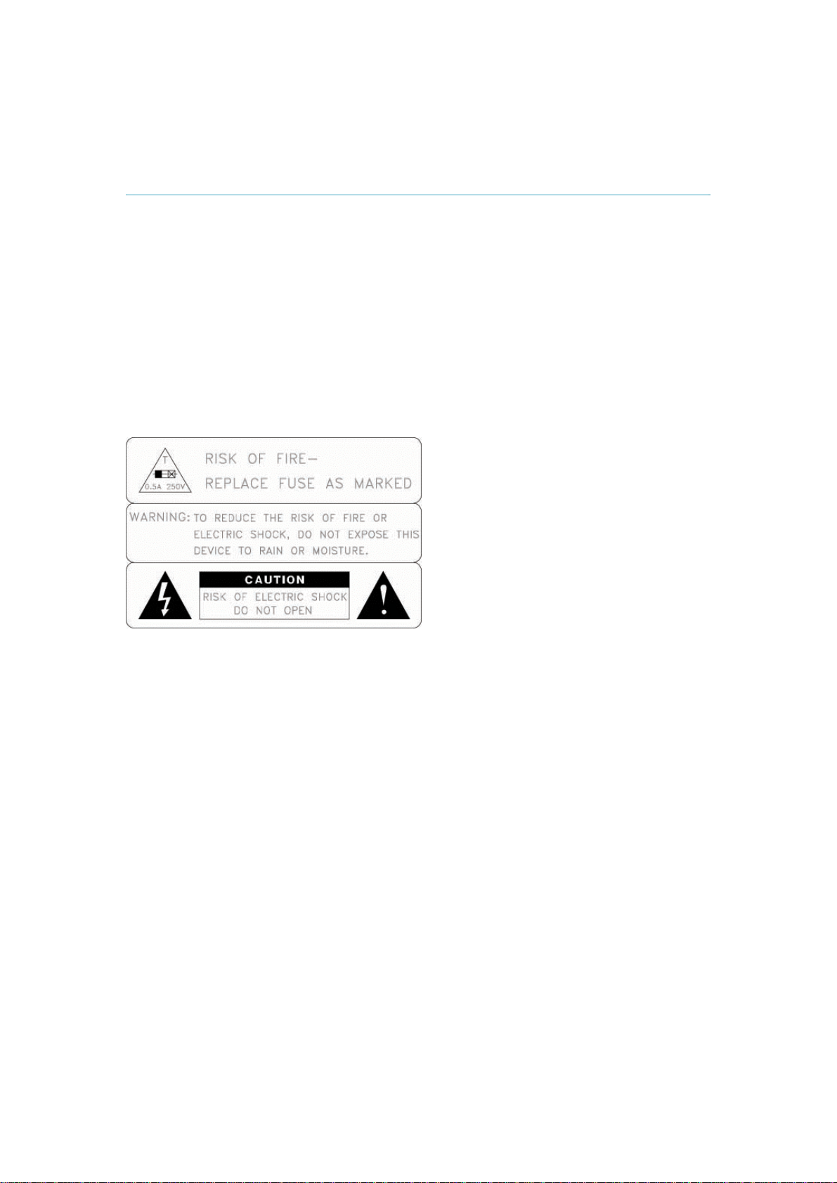
Equipment Markings
The lightning flash symbol within an equilateral triangle is intended to alert the user to the
presence of uninsulated “dangerous voltages” within the product’s enclosure that may be of
sufficient magnitude to constitute a risk of electrical shock.
The exclamation mark within an equilateral triangle is intended to alert the user to the
presence of important operating and maintenance (servicing) instructions within literature
accompanying the equipment.
Warnings
Water and moisture - Do not operate the equipment under or near water - for
example near a bathtub, kitchen sink, or laundry tub, in a wet basement, or near a
swimming pool or in areas with high humidity.
Cleaning - Unplug the apparatus from the wall outlet before cleaning or polishing. Do
not use liquid cleaners or aerosol cleaners. Use a lint-free cloth lightly moistened with
water for cleaning the exterior of the apparatus.
Ventilation - Do not block any of the ventilation openings of the apparatus. Install in
accordance with the installation instructions. Never cover the slots and openings with
a cloth or other material. Never install the apparatus near heat sources such as
radiators, heat registers, stoves, or other apparatus (including amplifiers) that
produce heat.
Grounding or Polarization - Do not defeat the safety purpose of the polarized or
grounding-type plug. A polarized plug has two blades with one wider than the other. A
grounding type plug has two blades and a third grounding prong. The wide blade or
third prong is provided for your safety. If the provided plug does not fit into your outlet,
consult an electrician.
Power-Cord Protection - Route the power cord so as to avoid it being walked on or
pinched by items placed upon or against it, paying particular attention to the plugs,
receptacles, and the point where the cord exits from the apparatus.
Attachments - Only use attachments as recommended by the manufacturer.
Accessories - Use only with a cart, stand, tripod, bracket, or table specified by the
manufacturer, or sold with the apparatus. When a cart is used, use caution when
moving the cart/apparatus combination to avoid injury from tip-over.
3

TANDBERG 1500 MXP
Lightning - Unplug this apparatus during lightning storms or when unused for long
periods of time.
ISDN cables - CAUTION - To reduce the risk of fire, use only No. 26 AWG or larger
telecommunication line cord.
Servicing - Do not attempt to service the apparatus yourself as opening or removing
covers may expose you to dangerous voltages or other hazards, and will void the
warranty. Refer all servicing to qualified service personnel.
Damaged Equipment - Unplug the apparatus from the outlet and refer servicing to
qualified personnel under the following conditions:
When the power cord or plug is damaged or frayed
If liquid has been spilled or objects have fallen into the apparatus
If the apparatus has been exposed to rain or moisture
If the apparatus has been subjected to excessive shock by being dropped, or
the cabinet has been damaged
If the apparatus fails to operate in accordance with the operating instructions
4

1 Introduction
The TANDBERG 1500 MXP system offers superior audio and video quality in a fully featured
unit. MXP stands for Media Experience and indicates the new TANDBERG platform.
Main Features:
Supports videoconferencing via both IP and ISDN networks.
Selection of up to 1,1 Mbps call quality.
Built-in MultiSite
Secure Conference
privacy and security.
Natural Presenter Package* (NPP) consisting of:
Natural VideoTF – provides 60 fields per second true interlaced picture.
DownspeedingTF - if channels are dropped during a videoconferencing session, the
connection is automatically maintained without interruption.
Streaming – allows broadcasting of audio/video via an IP network.
Web-interface for streaming, text chat/closed captioning, system management,
diagnostics and software uploads.
Worldwide compatibility with other standards-based videoconferencing systems.
What's new:
New Graphical User Interface including new Remote Control
High quality audio (MPEG-4 AAC-LD)
SXGA (h)Tj46 0 TD(i)Tj1836 TD(l)Tj18 0D(e)Tj47 0 TD( )Tj23 0 TD(nTD(t)Tj24 0 TD(i)Tj8TD(o)Tj46 0 T87j29 0 TDdr)Tj28 0 TD(f g0 G23 0 T(l)Tjr)Tj28 0 TD(a)Tj46 0 TD(p)Tj47 0 TD(h)Tj46 0 TD7 0 TD(l)Tj183 Tm(!)Tj38 0D( )Tj23 0 TD(s)Tj42TDdrf g0 G23 0 T(l)Tjrd7/F0 83 Tf1 046 0 TD(g)Tj46 0 T(w)Tj59 0 TD(i)To 0 TD(a)Tj46 0 TD bur
TF
*:
A maximum of 4 sites + 3 additional telephone calls can participate in
joint meetings.
Auto Split, Voice Switched, 4 Split and 3+1 Split picture modes
supported.
Any combination of ISDN and IP participants is possible.
Supporting H239, DuoVideo, Encryption and H264
The TANDBERG videoconferencing system can also be used purely
as an audio-bridge (with an ISDN connection).
TF -
Embedded encryption for both Point-to-Point and MultiSite call
Duo VideoTF - allows participants at the far end to simultaneously
watch a presenter on one screen and a live presentation on the
adjoining screen.
Digital ClarityTF - participants enjoy presentations of exceptionally high
quality resolution video.
PC PresenterTF - an easily accessible PC connection over Ethernet
that supports up to XGA resolution.
PC SoftPresenterTF - show PC images via your LAN connection
supporting XGA resolution.
5
TANDBERG 1500 MXP
1.1 At a Glance
6

1 Introduction
The remote control uses 4 AAA batteries. The system will tell you when batteries are running
low. Change batteries from the backside of the remote control.
The reach of the remote control signal is 20 meters. For users sitting in an open plan office,
this can cause problems. Use the little, white switch placed under the batteries to change the
reach of the signal from 20 meters to 2 meters. This will prevent you from unintentionally
controlling your neighbor's video system, when you control your own system.
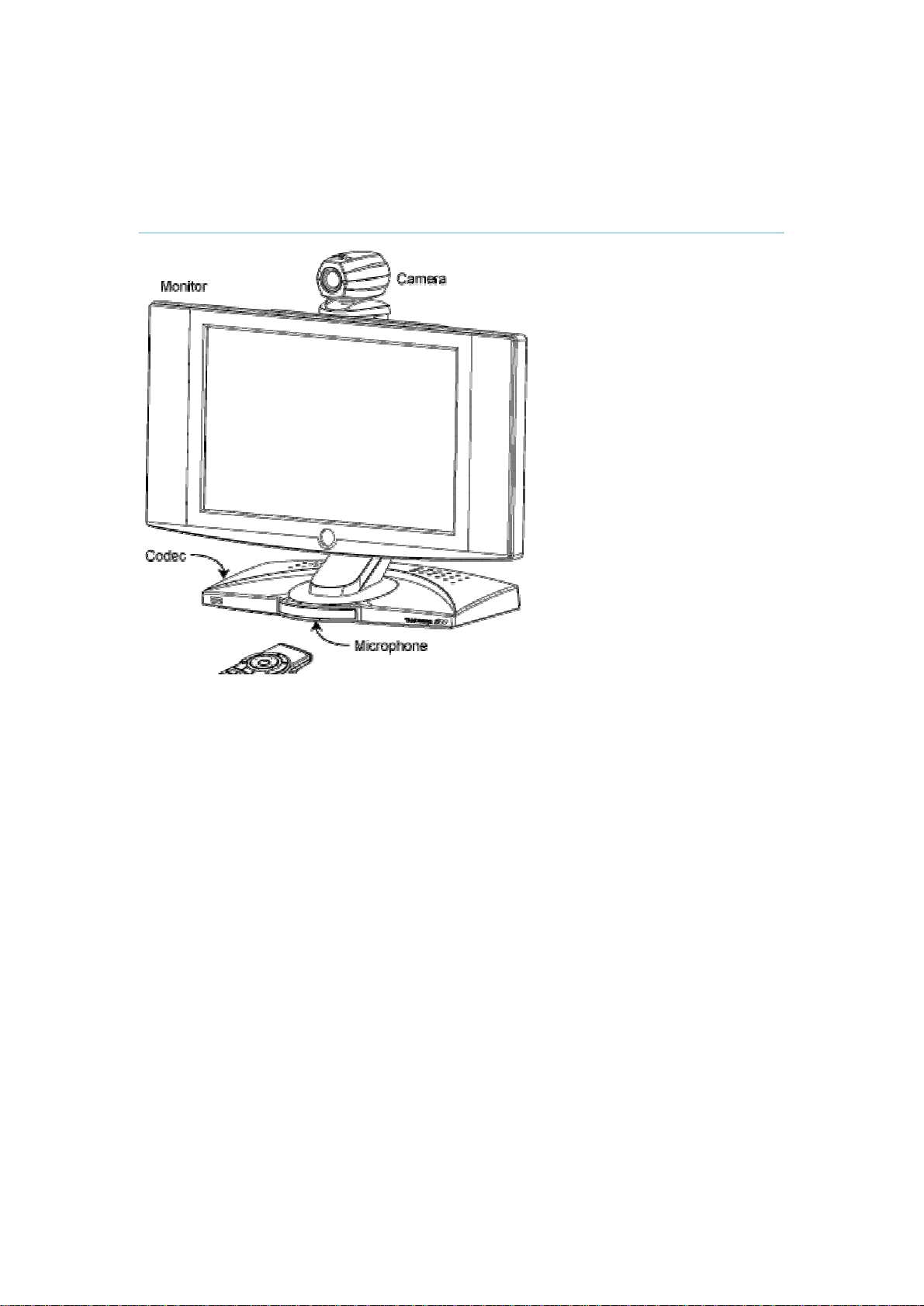
Microphone
The microphone is integrated in the rubber foot supporting the front of the codec. This is an
ideal location for the high quality voice pickup needed during a videoconference. Sound
reaches the microphone through a small hole in the rubber. Care should be taken not to cover
up the hole, as this may lead to deterioration of sound quality. Any liquid spilled should be
cleaned up immediately to avoid damage to the microphone.
7
TANDBERG 1500 MXP
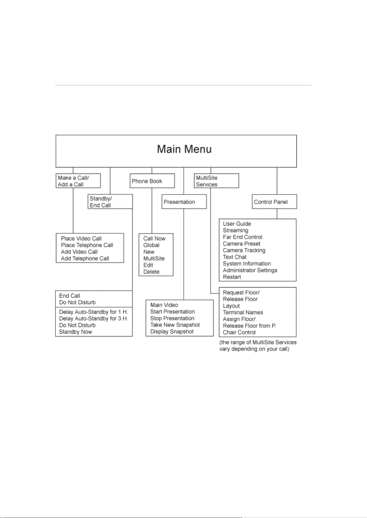
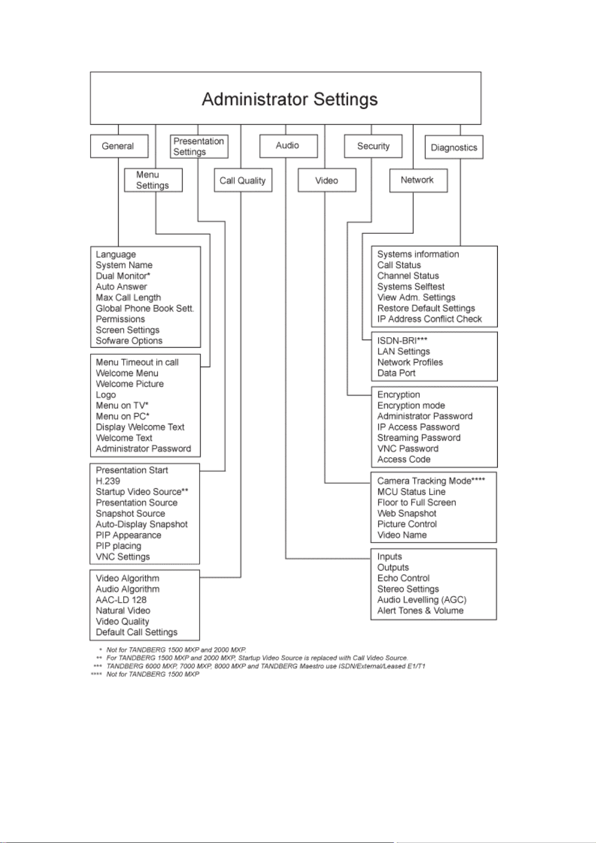
1.2 Menu Structure
The menu structure is divided in two. The Main Menu is available for all users and contains all
functionality of the system. The Administrator Menu contains all the settings of the system.
Enter Administrator Settings from Main Menu - Control Panel. Making changes to the
Administrator Settings will change the behavior of the system. The menu structure for Main
Menu and Administrator Settings is shown below.
8
1 Introduction
9

2 Installation
Precautions:
Never install communication wiring during a lightning storm.
Never install jacks for communication cables in wet locations unless the jack is
specifically designed for wet locations.
Never touch uninstalled communication wires or terminals unless the telephone line
has been disconnected at the network interface.
Use caution when installing or modifying communication lines.
Avoid using communication equipment (other than a cordless type) during an
electrical storm. There may be a remote risk of electrical shock from lightning.
Do not use the communication equipment to report a gas leak in the vicinity of the
leak.
Always connect the product to an earthed socket outlet.
The socket outlet shall be installed near to the equipment and shall be easily
accessible.
Never install cables without first switching the power OFF.
1TR6 network type is not approved for connection directly to the telecommunications
network. This network type is only to be used behind a PABX.
This product complies with directives: LVD 73/23/EC, EMC 89/366/EEC, R&TTE
99/5/EEC
10
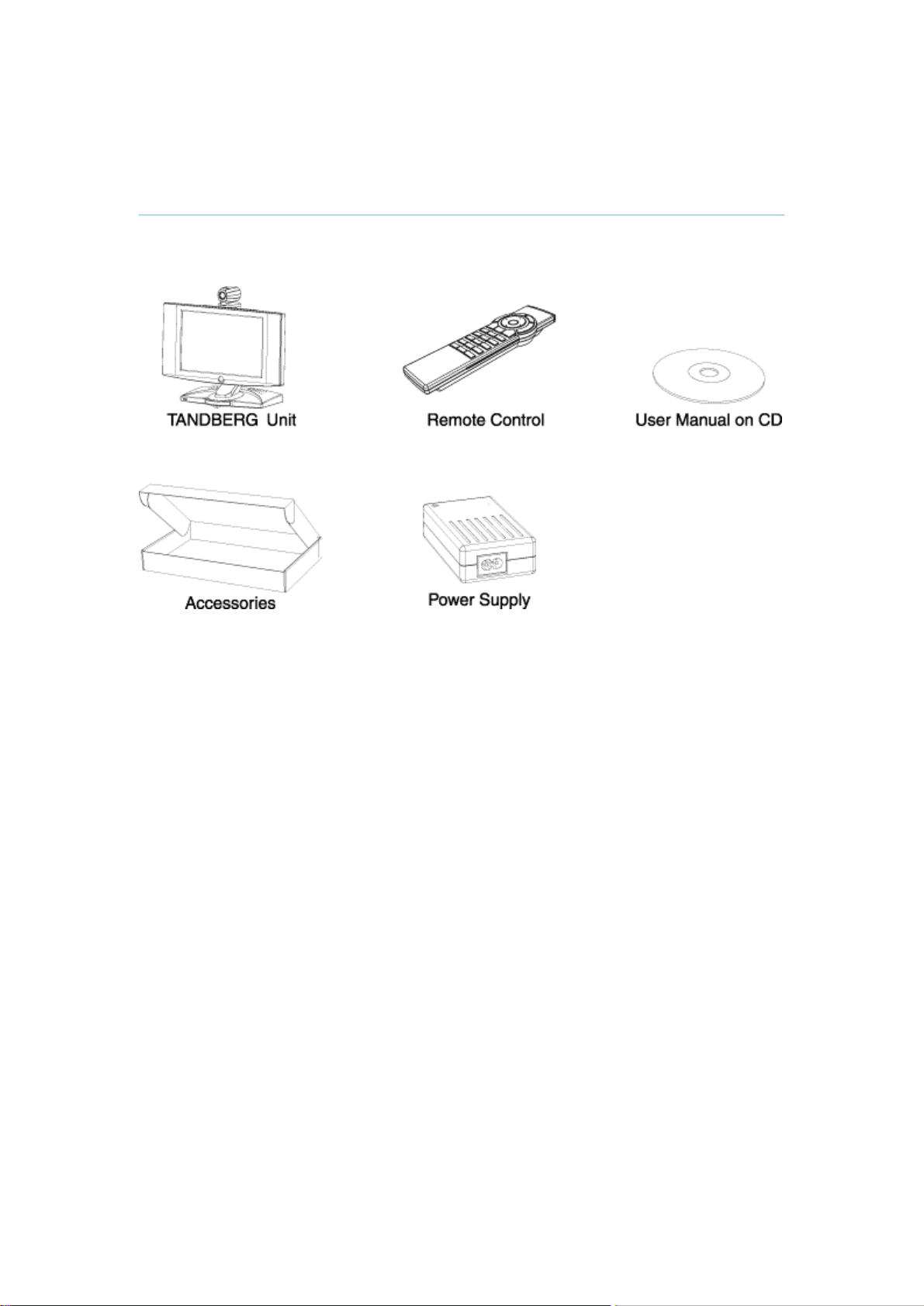
2.1 Unpacking
2 Installation
When unpacking the TANDBERG 1500 MXP, you will find the following items:
11
TANDBERG 1500 MXP
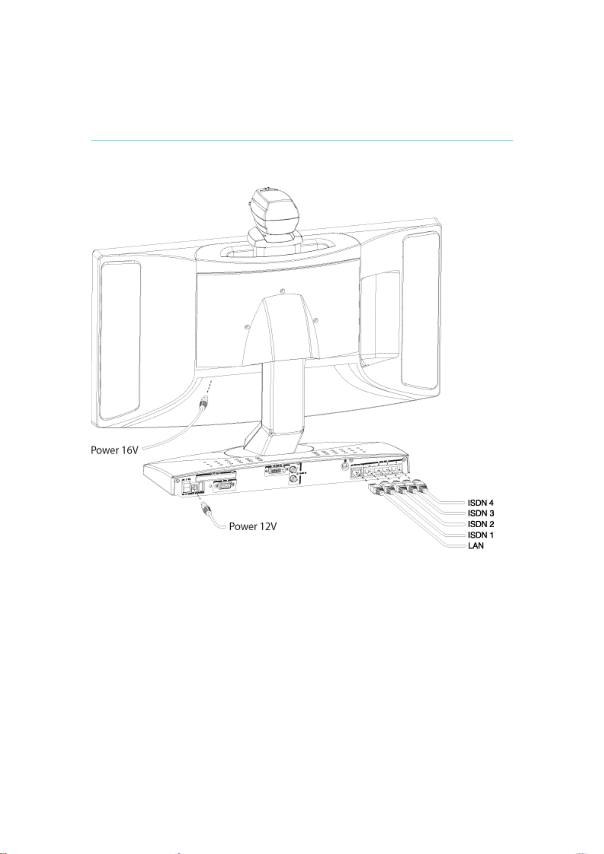
2.2 Connecting Cables
Connect the cables according to the figure below:
12
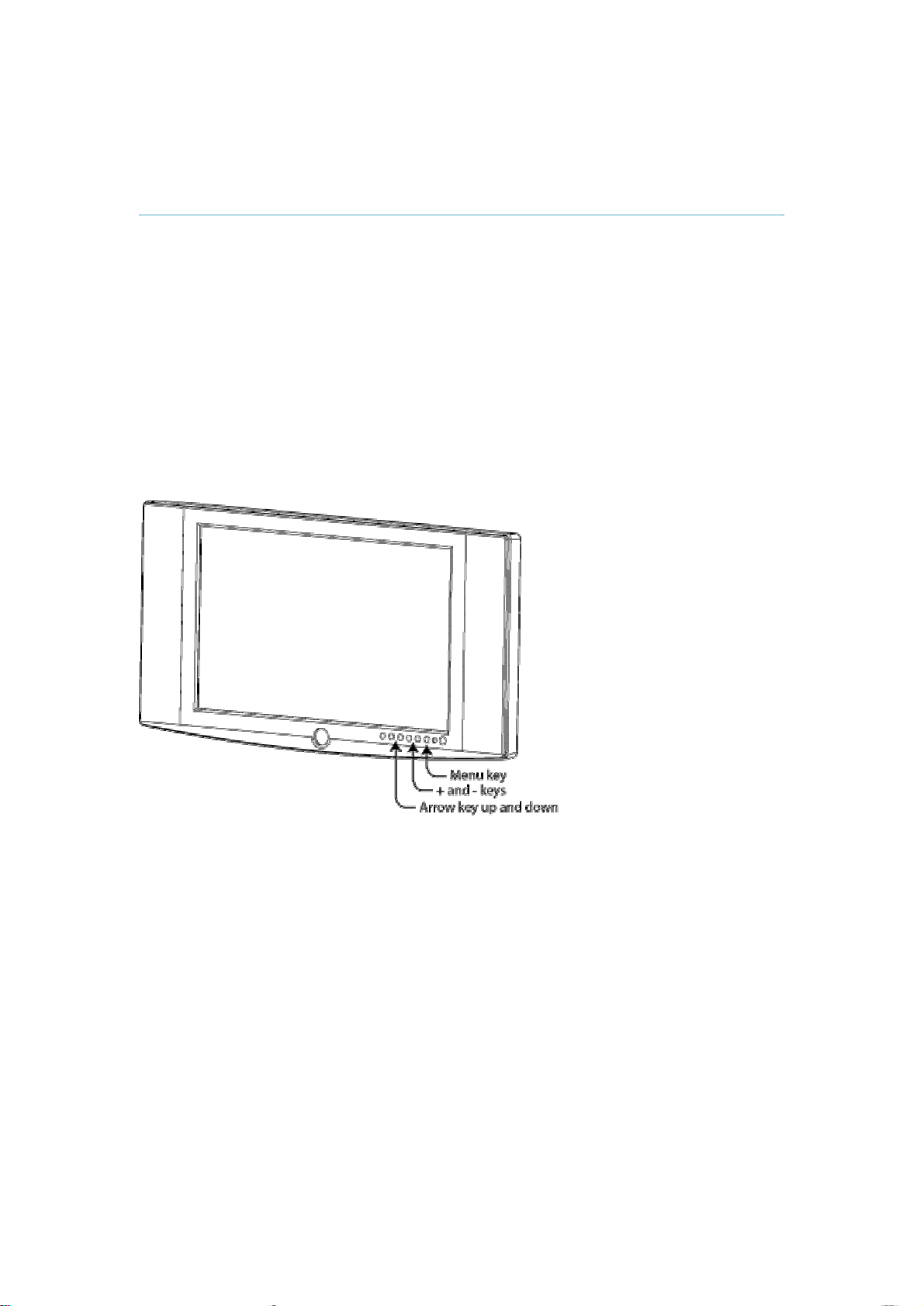
2.3 Monitor Configuration
2 Installation
Before you start using the system, make sure that your monitor uses your desired language.
Also, make sure that surround sound is OFF.
How to change the monitor language:
1. Press the menu key on the monitor to bring up the monitor menu. The menu key is
the 6.th key from the left.
2. Press arrow key down 7 times to select Language. The arrow key down button is the
2.nd key from the left.
3. Press menu key to select Language.
4. User arrow keys to select your desired language.
5. Press menu key to confirm.
6. Press the menu key again to exit the monitor menu.
How to set surround sound to OFF:
1. Press the menu key on the monitor.
2. Choose Audio by pressing arrow down 3 times. Press the menu key to select.
3. Choose Surround by pressing arrow key down 5 times. Change the setting using the
+ and - keys.
4. Press the menu key again to exit the menu.
13
TANDBERG 1500 MXP
2.4 System Configuration
The system must be configured for each installation. Configuration settings can be made via
the system menu.
Navigate through the menu system using the arrow keys and OK. Remember to press the
Save button on the bottom of each menu to save your changes. Press Cancel (x) to return to
the previous Menu. See next section for more information about how to use the menus and
the remote control.
General configuration:
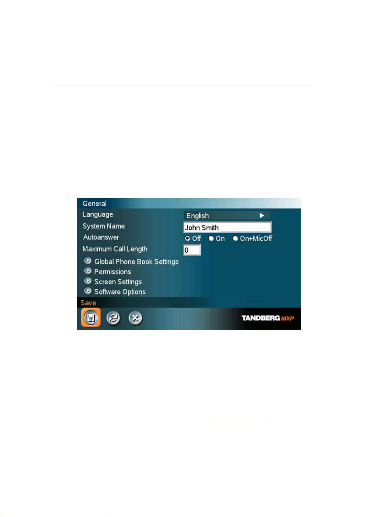
1. Open the General Settings menu
Press OK to open the Main Menu (if it is not already open).
Select Control Panel and then select Administrator Settings. Select General to
open the General Settings menu.
14
2. Language
Press OK in the Language field and select the language you want to use from the
list.
3. System Name
Enter a name in the System Name field using the number keys on the remote
control, as you would do with a mobile or cellular phone.
4. Auto Answer, Max Call Length, Global Phone Book Settings and
Permissions
Leave Auto Answer, Max Call Length, Access code and Permissions unchanged
if no special needs are required. See chapter 4.1 General Settings for more
information.
5. Screen Settings
When using wide screen (16:9) monitors, set TV Monitor Format to Wide (16:9).
TANDBERG also recommends setting Picture Layout to Picture outside Picture
when using 16:9 monitors. Picture outside Picture provides a display layout
optimized for wide screen monitors. The display layout may be changed at any
time using the Layout button on the remote control.
6. Software Options
To activate MultiSite and/or Presenter and bandwidth, you must enter a new
option key in the Software Options menu (see paperwork accompanying your
system). For more information on these options, contact your TANDBERG
representative.
7. Save changes
Remember to save any changes you make in a menu by selecting the Save
button on the Menu line and pressing OK.
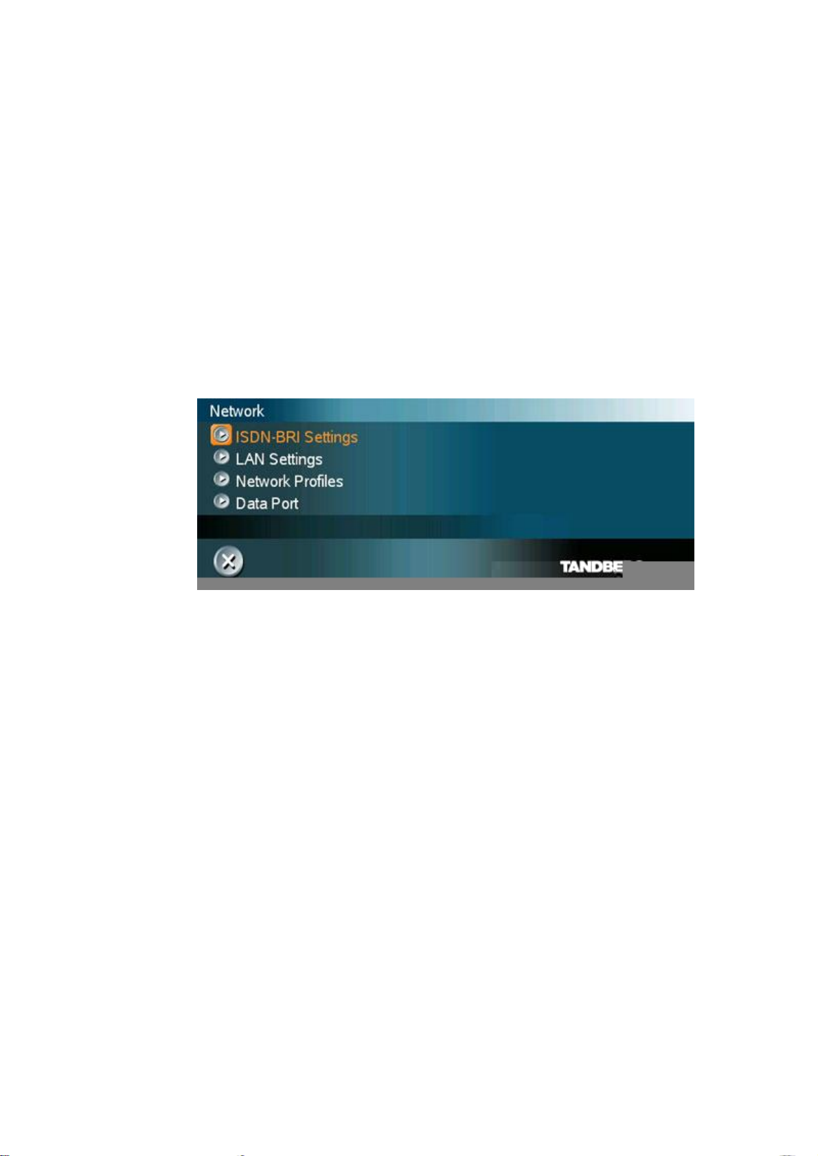
Network configuration:
1. Open the Network menu
Open the Administrator Settings menu and choose Network.
2 Installation
15

3 General Use
Wake up the system
When the system is not in use, it is in standby mode and the screen is black. Wake up the
system by picking up the remote control. An incoming call or pressing any key on the remote
will also wake up the system.
If the system does not respond:
Make sure that the system is switched on by using the On/Off switch located at the
rear of the Codec.
Verify that your monitor is switched on. To switch the monitor on, push the power
button on the front of the monitor (the button on the far right).
16
3.1 The Welcome Screen
3 General Use
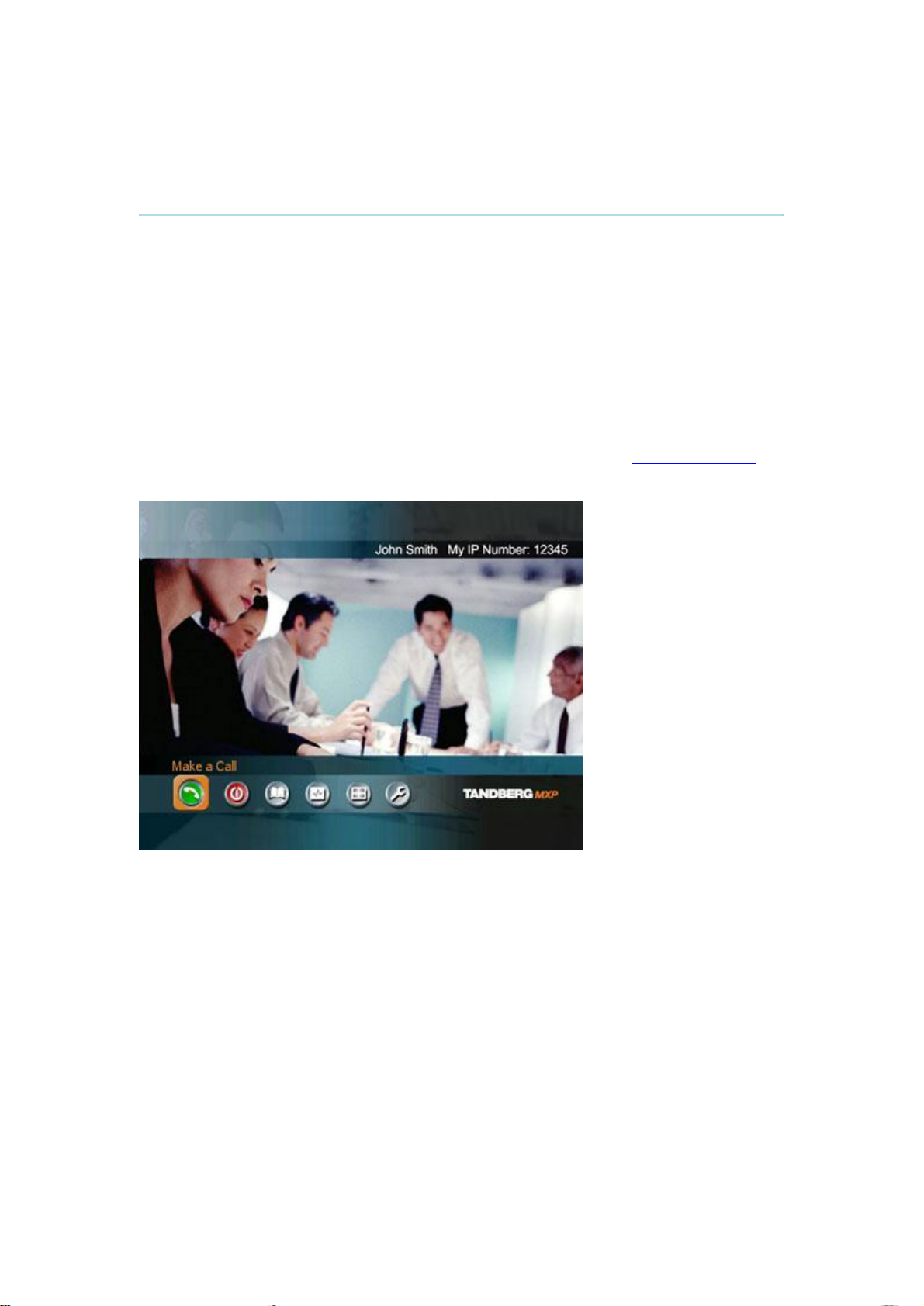
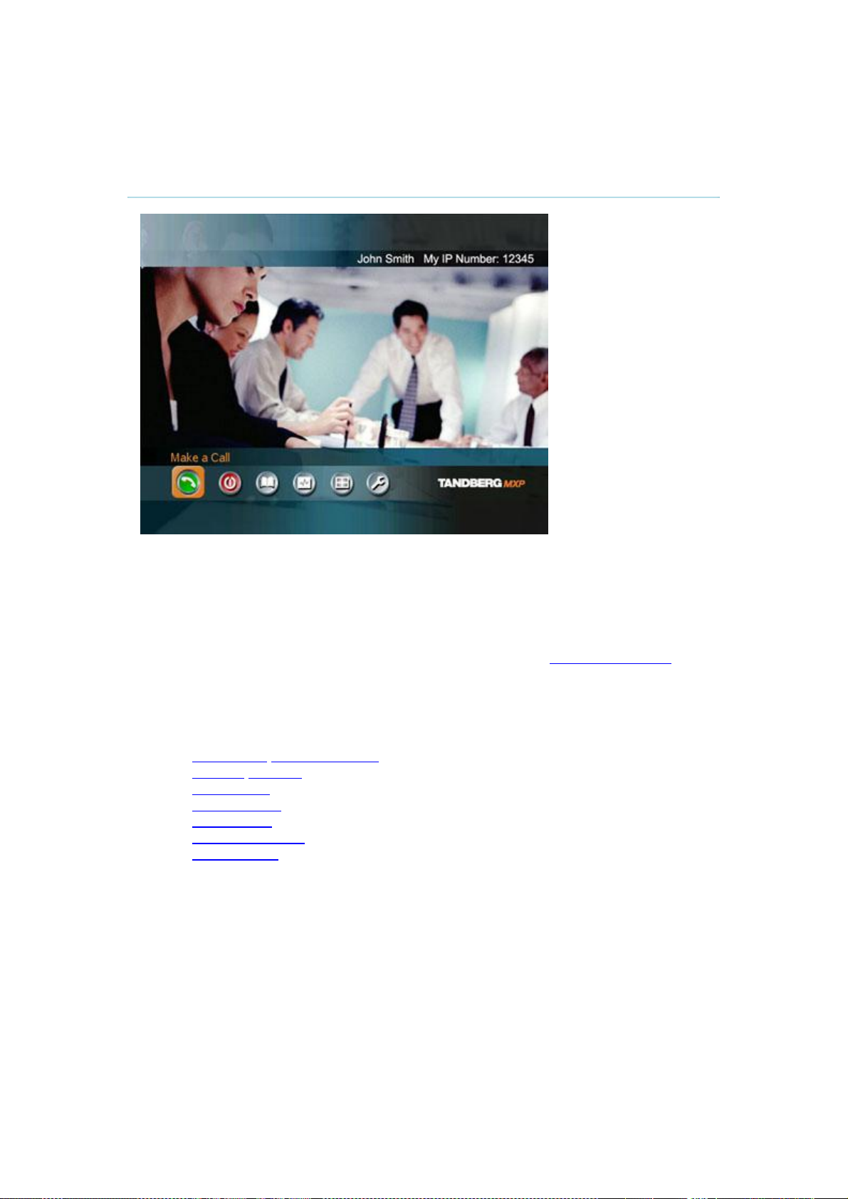
When the system is switched on, you will see the welcome screen. The welcome screen
presents the Main Menu and displays your Main Camera image in the background (Main
Camera is system default). Your dial in numbers and system name are displayed in the upper
right corner. Your ISDN Number and IP Number are the numbers that your contacts need to
place a video call to you.
The welcome screen also provides you with the most important system information:
System Name
Your ISDN Number
Your IP Address or IP Number
It is possible to customize the text on the welcome screen. See chapter 4.2 Menu Settings for
how to edit welcome text.
17
TANDBERG 1500 MXP
3.2 Using the Remote Control
The system is controlled with a remote control. Think of the remote control as a mobile phone
with number keys and call keys. Use the arrow keys and OK to navigate the menu. The
system’s most commonly used functions are also accessible directly from the remote control.
The Infra Red (IR) sensor for the remote control is located in front of the WAVE II Camera.
There is also a second IR-sensor located in the front of the Codec itself, which will be
automatically enabled if the WAVE II Camera is not connected.
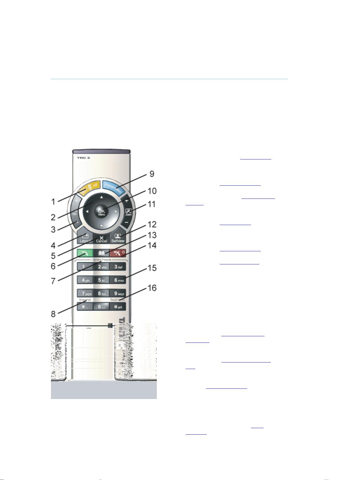
1. Mic Off turns your microphone on
and off. (See chapter 3.2.4 Mic off)
2. Arrow keys are used for navigation
in the menu and for moving the
camera when the menu is hidden.
(See chapter 3.2.1 Navigation)
3. Volume + and – adjusts the system
volume. (See chapter 3.2.5 Volume
+ and -)
4. The Layout key toggles between full
screen and different display layouts.
(See chapter 3.2.3 Layout)
5. Cancel takes you back one step in
the menu system. Use Cancel to
delete characters in an input field.
(See chapter 3.2.1 Navigation)
6. Press the Call key to place a call.
(See chapter 3.5 Make a Call)
7. Camera presets define specific
camera positions. Press and hold a
number key for 1 second to save the
current camera position to that
number key. To activate a preset
whilst in a call, simply press and
release that number key. (See
chapter 3.10.3 Camera Presets)
8. Snapshot takes a snapshot of your
video. (Only while you are in a call)
(See chapter 3.11.6 Take New
Snapshot)
9. The Presentation key switches to a
predefined presentation source.
(See chapter 3.11.1 Presentation
Key)
10. Press OK/Menu to show the menu
and to select menu items. (See
chapter 3.2.1 Navigation)
11. Use Zoom + and – to zoom the
camera in and out. (See chapter
3.10.1 Zoom)
12. Selfview displays your outgoing
video. Press Selfview again to turn
selfview off. (See chapter 3.2.2
Selfview
18

3 General Use
13. Store and recall your video contacts via the system Phone Book for easy placement
of calls. (See chapter 3.9 Phone Book)
14. Use the red End Call key to end the current call. Pressing this key when not in a cTj23 0 TD(B)Tj55 0 TD(o)Tj47 ( )Tj24 0 TD(w)Tj59 0 TD7 a3ll i0 TD7 a3y ement system Pho cTe rh
19
TANDBERG 1500 MXP
3.2.3 Layout
The Layout button has two behaviors depending on the Picture Layout setting in Administrator
Settings (see chapter 4.1.8 Screen Settings). It can provide either a Picture in Picture or a
Picture outside Picture.
3.2.3.1 Picture in Picture
With Picture in Picture (PIP), Layout makes it possible to see an extra picture in a smaller
view. Pressing Layout will bring up a picture in picture in the corner of the screen. Press
Layout again to move it to the other corners of the screen and finally hide it. You can also
hide it directly by pressing and holding Layout for 1 second. Picture in picture will always
appear on the main monitor. Automatic PIP is the system's default setting. That means that
you will automatically show Picture in Picture when it is suitable (see chapter 4.3 Presentation
Settings).
How to use Layout with Picture in Picture:
1. Press Layout once to bring up a picture in picture.
2. Press Layout three more times to move it around in the corners of the screen.
3. The fourth time you press Layout, it will disappear.
4. Pressing and holding Layout for 1 second will hide the small picture directly from any
position.
Example of PIP
3.2.3.2 Picture outside Picture
With Picture outside Picture (POP), pressing Layout will bring up compositions of the pictures
that are optimized for wide screens. Press once to get an extra picture in a smaller view.
Press twice to get side-by-side view. Press again to go back to full screen view. You can also
go back to full screen directly by pressing and holding Layout for 1 second. It is
recommended to use Picture outside Picture for wide screen monitor systems.
How to use Layout (Picture outside Picture):
1. Press Layout once to get the 1+3 layout. You see a big far end picture and a smaller
picture of yourself in the upper right corner. If you use Duo Video, you see a big
picture of the Duo Video and small pictures of the far end and yourself.
2. Press Layout again to get the side-by-side layout (1+1). You see two equally big
images of the far end and yourself.
3. The third time you press Layout you go back to normal full screen view.
4. Pressing and holding Layout for 1 second will bring you back to full screen anytime.
20
3 General Use
Note that if both TV monitor format and VGA format (in Administrator Settings\General\Screen
Settings) is set to Normal, the system will skip the 1+3 layout, which is not beneficial for 4:3
monitors.
Example of POP
21

TANDBERG 1500 MXP
3.2.5 Volume + and -
Press the Volume key to adjust the volume level. An on-screen indicator will show the current
level.
3.2.6 Number and Letter keys
Pressing a number key when you are outside a call will take you to the call menu. When you
are in a call, the number keys are used for Camera Presets. Press a number and you go to
the corresponding Camera Preset (see chapter 3.10.3 Camera Presets). However, when you
are in an input field where numbers are required, the system automatically goes to number
mode and you can dial numbers with the number keys as usual.
When you are in an input field where letters are required, the system automatically goes to
letter mode. Writing letters works like on a mobile phone. Press the key that corresponds to
your desired letter. Press the key as many times as you need to get the right letter. Change to
lower or back to upper case letters with the a/A key, and space with the 0 _ key.
To write numbers in a text input field, press the button through all the letters. Press once more
and the number will appear.
Example: How do I write "System 123" in the System Name input field (in General in
Administrator Settings)?
Press the 7-key four times to get an "S".
Press the #-key once to switch between upper case and lower case letters.
Press the 9-key three times to get a "y".
Press the 7-key four times to get an "s".
Press the 8-key once to get a "t".
Press the 3-key twice to get an "e".
Press the 6-key once to get an "m".
Press the 0-key once to get space.
22
Press the 1-key three times to get a "1".
Press the 2-key four times to get a "2".
Press the 3-key four times to get a "3".
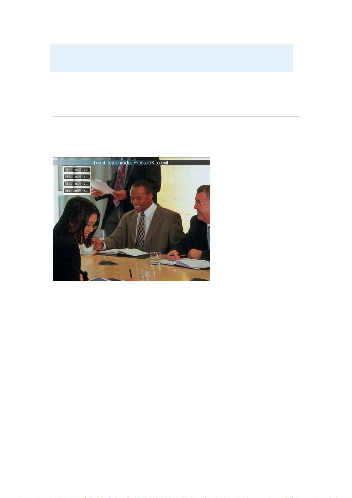
3.2.7 Touch Tones
3 General Use
Sometimes you need to dial extension numbers with the number keys when you are in a call.
Pressing numbers will result in a camera preset. In these cases, press # to enable Touch
tones. An indicator will tell that touch tones are enabled. Now you can enter your extension
number with the number keys. Finish with OK to exit Touch tones mode.
23
TANDBERG 1500 MXP
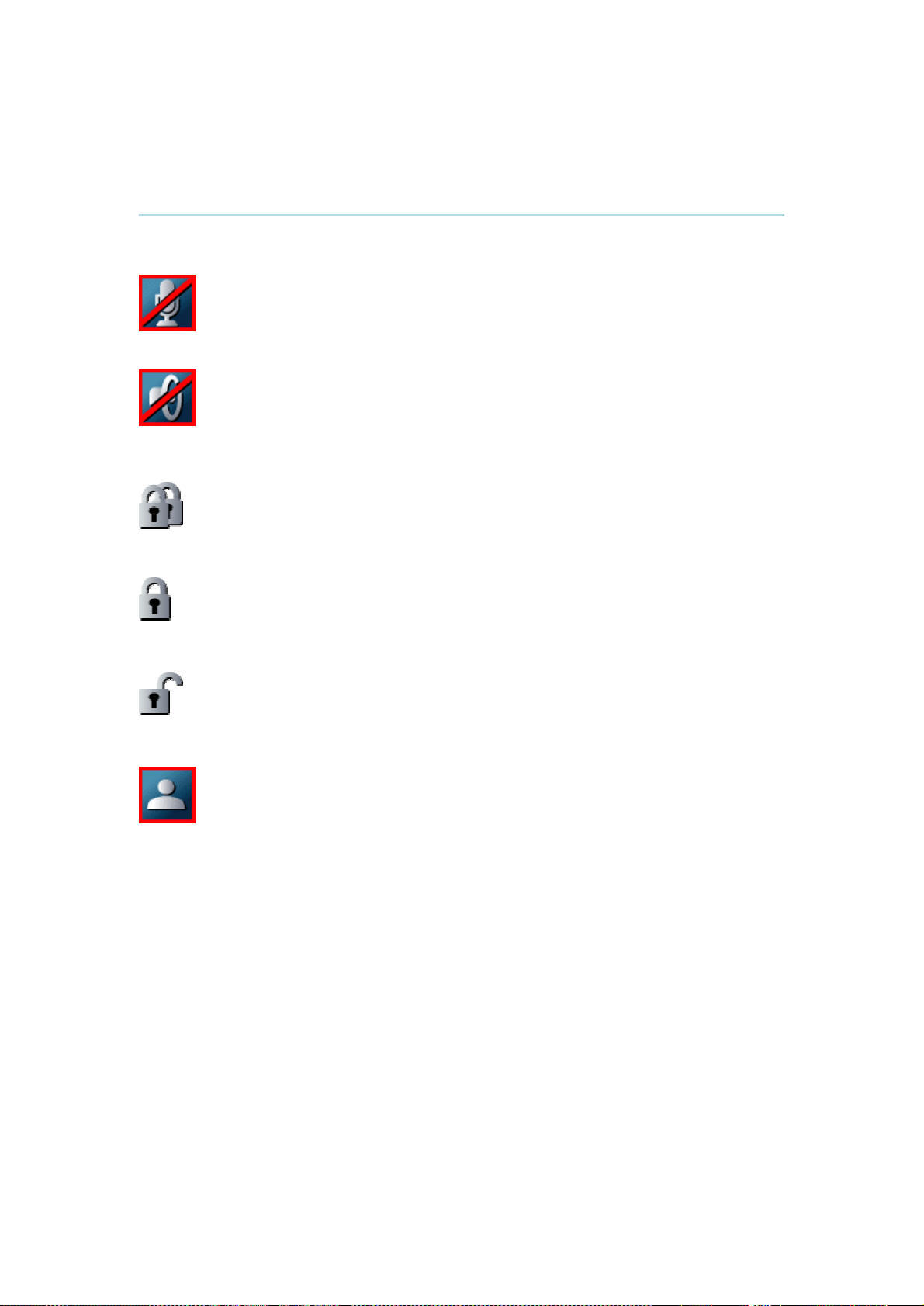
3.3 On Screen Indicators
The system has a number of icons signaling different settings:
Microphone Off
This indicator is shown when the microphone is turned off. Press the Mic off
button again to turn the microphone back on.
Volume Off
This indicator is shown when the volume is turned off. Press Volume + to turn
the volume back on.
Secure Conference, AES
This double padlock indicator is shown when AES encryption (Secure
Conference) is active.
Secure Conference, DES
This padlock indicator is shown when DES encryption (Secure Conference) is
active.
Not Secure Conference
This open padlock indicator is shown during the initialization phase for
encryption. During this period the call is not secure.
Floor
This indicator is shown when you are displayed in full screen in a MultiSite
conference.
24
3.4 Using the Menu
3 General Use
Main menu.
The menu is the Interface you will use to control the system. The main menu contains:
Make a Call, Standby, Phone Book, Presentation, MultiSite Services and Control Panel.
When you are in a call, Add another Call and End Call will be available via the green and
red buttons.
The menu automatically times out after 15 seconds (see chapter 4.2.1 Menu timeout).
Press OK/Menu to bring it back. You can also hide the menu manually by pressing Cancel
(X) in the main menu.
This chapter describes:
Make a Call/Add Another Call
Standby/End Call
Phone Book
Move Camera
Presentation
MultiSite Services
Control Panel
25

TANDBERG 1500 MXP
3.5 Make a Call
26

3 General Use
3.5.2 Place Telephone Call
The TANDBERG system has great audio- as well as video performance. Use the system both
as a videophone and a telephone!
How to place a telephone call:
1. Press the green key on the remote or choose Make a Call from the Main Menu to
open the Call menu.
2. Dial a telephone number with the number keys.
3. Move the yellow selector down to the Place Telephone Call icon and press OK to
start the telephone call.
When you dial a telephone number and press the green key on the remote, the system will in
most cases automatically interpret the number as a telephone number and not a video
number. The interpretation can sometimes take a little while. If you want to make a telephone
call in a quicker way, it is recommended to use the Place Telephone Call button in the menu.
3.5.3 Add Call
(optional feature)
TANDBERG system's built-in MultiSite can handle video calls and telephone calls including
yourself. With the Add Call buttons it is possible to connect to several participants
simultaneously, avoiding dialing each participant one by one, which can be time consuming.
Press Add Call to get the desired amount of participants to your MultiSite call.
How to use Add Call:
1. Press the green key on the remote or choose Make a Call from the Main Menu to
open the Call Menu.
27

TANDBERG 1500 MXP
2. Choose Add Video Call or Add Telephone Call from the menu line. An extra number
field appears. Press the Add button until you have the desired number of participants
(press Cancel inside an empty input field to delete the field).
3. Dial Numbers with the number keys.
4. Press Make Video Call to start the videoconference. If you have a mixed conference
with both video and telephone participants, press Make Video Call. Press the Make
Telephone Call if you want to start a conference with telephones only.
28

3 General Use
Call Type
Network
Bandwidth
Restrict
(56k)
Use Set as
Default
Call Type can be set to Video Call (default) or Telephone Call. Using
Video, the system will try to connect as a video call. Some network
configurations will cause the fallback to a telephone call to fail. In these
cases, you should set the call type to telephone and the call will be placed
as a telephone type only. For MultiSite calls, Call Type enables you to
specify both telephone calls and video calls in the same conference.
The Network alternatives are: Auto, ISDN and H.323 (LAN). The system
will, by default, try to connect using Auto Network. That means that the
system will automatically use the right network depending on the number
you have dialed.
If Auto is selected, the system will select a network based upon the
following criteria:
If an IP-address (e.g. 10.12.34.56 ) is entered, H.323 (LAN) is
selected.
If the first digits in the number match those set in H.323 Prefix
under H.323 Settings, LAN is selected.
In other cases, ISDN (H.320) is selected.
If you need to ensure that you make an H.323 or ISDN call, specify this by
choosing H.323 or ISDN. ISDN indicates ISDN-BRI, ISDN-PRI, Leased
E1/T1 and External Networks. If a gatekeeper is present, you may place
IP-calls using “telephone-style” numbers (an E.164 alias), according to the
numbering plan implemented in the gatekeeper. The gatekeeper will then
translate the dialed number into an IP-address (see chapter 4.8.2.2 H.323
Settings for more information about gatekeepers).
Bandwidth decides the quality of the video picture. The system will, by
default, connect using Auto Bandwidth. This means that the system will
establish a connection using a proper bandwidth for your call.
The typical bandwidths used for ISDN and IP calls are 384kbps and
768kbps respectively. When bandwidth is set to auto, the unit will default
to 384kbps for ISDN calls and 768kbps for IP calls.
A restricted call is a call that uses 56kbps channels rather then the default
unrestricted 64kbps channels. Some older networks (primarily in the USA)
do not support 64kbps channels and require the use of restricted 56kbps
calls. By default the system will dial an unrestricted call and downspeed to
56kbps if necessary. To force a restricted call, choose Restrict (56k) On.
An indicator “(56k)” will be shown beside the number.
If you want to change the default Call Settings, make the desired changes
to the Call Settings and Press Set as Default. Press OK to Save. These
settings will now be the default settings for all future manually dialed calls.
29

TANDBERG 1500 MXP
Type of calls*
Auto: 384 kbps on ISDN/768 kbps on LAN
Max: 512 kbps on ISDN-BRI
2Mbps (1920 kbps, IP only)
1472 kbps = 23B, IP only
1152 kbps = 18B, IP only
768 kbps = 12B, IP only
512 kbps = 8B
384 kbps = 6B
320 kbps = 5B
256 kbps = 4B
192 kbps = 3B
128 kbps = 2B, Bonding/H.221
64 kbps = 1B, H.221
*Some software versions and networks do not support all channel selections.
H.221 or 2x64 (2x56) Calling
Some older or low end video systems do not have the ability to make bonded ISDN calls. In
these cases you may have to dial both ISDN numbers separately to call those systems.
These types of calls are often referred to as H.221 calls, 2x64 calls, or 2x56 calls, as you are
making 2 x 64 kbps or 2 x 56 kbps calls to the same system. To place this type of call, set
bandwidth to 128 kbps and Network to ISDN. A field for 2nd number pops up in Call Settings.
Enter the first number in the call menu and the second number in the Call Settings field. For
128 kbps calls that use bonding, ignore the second number field and just enter one number to
be dialed.
Using sub-address / extension address / MCU password
Sub-address is used to address different systems on the same ISDN line and is primarily
used in European Countries. TCS-4 is used to address different systems on a LAN, when
dialing in via a gateway.
To specify an ISDN sub-address or its LAN equivalent extension address (TCS-4), add a star
(*) after the number and then enter the sub-address/extension address.
Example:
12345678*10 ( <number>*<Sub-address/extension address/MCU password>)
When calling to external MCU’s requiring a password (TSC-1), this password can be added
after the star (*). If no password is specified, a menu will prompt you to enter the password
(after connecting to the MCU).
30

3.6 Answer an incoming Call
3 General Use
You can receive calls anytime, even when the system is in standby mode. But remember to
switch the system on using the On/Off switch located at the rear of the system as described in
chapter 3 General Use.
How to answer an incoming call:
1. To accept an incoming call, press OK or the green key on the remote control.
2. Press the red key on the remote control to reject the incoming call.
3. If you do not want any incoming calls, choose Do Not Disturb. If Do Not Disturb is on,
the system will automatically reject all incoming calls. See Chapter 3.8.3 Do Not
Disturb for further details.
If Auto Answer is set to On, an incoming call will connect automatically. You can set Auto
Answer On, On + Mic Off or Off in Administrator Settings\General Settings, see chapter 4.1.4
Autoanswer.
31

TANDBERG 1500 MXP
3.7 End Call
The remote control works much like a mobile/cellular phone. Press End Call from the main
menu or the red key on the remote control. In the End Call dialog box, press End Call again.
Press Cancel (x) to continue the call.
How to end a call:
1. Press the red key on the remote control or End Call from the main menu.
2. Press the red key on the remote control again or OK to confirm that you want to end
the call.
32

3.8 Standby
3 General Use
The system will automatically go to Standby mode when it is not in use. You can also choose
Standby from the main menu (outside a call) to put the system to standby. In standby mode,
the screen(s) are black. It is however still possible to receive incoming calls.
The monitors should always remain powered on and the stand-by mode of the system should
be used if the system is to be left idle.
Note! You will not turn your system to standby by switching off the monitors.
How to use standby mode:
1. Press the red key on the remote control or choose Standby from the main menu
when you are outside a call.
2. Press the red key again or choose Standby Now from the Standby menu.
3. The screen(s) turns black.
4. To wake up the system again, pick up the remote control, or press any of its keys.
3.8.1 Delay Auto-Standby for 1 hour
Delay Standby for 1 hour postpones the automatic standby mode for 1 hour. Use Delay 1
hour if you want to prevent the system from going to standby automatically. This is useful if
you want to use the monitors for a local presentation and prevent the system from
automatically blanking out the monitors because the video system itself is idle.
3.8.2 Delay Auto-Standby for 3 hours
Delay Standby for 3 hours postpones the automatic standby mode for 3 hours.
33

TANDBERG 1500 MXP
3.8.3 Do Not Disturb
Do Not Disturb means that the system will not accept any incoming calls. The caller will hear
a busy tone when calling this unit. An indicator will indicate when Do Not Disturb is active.
End Do Not Disturb by pressing any key on the remote control. The indicator will disappear.
34

3.9 Phone Book
3 General Use
The local Phone Book stores up to 200 contacts including the last numbers dialed. Using the
Phone Book is time saving and makes sure you do not inadvertently call the wrong number.
The contacts are sorted alphabetically. Navigate the phone book with arrow keys or letter
keys, searching on the first letter (like on a mobile/cellular phone). Press arrow to the left to
select a button. You will see that the last selected contact will be marked. An arrow beside a
contact indicates that this is a MultiSite. The first entry, Last Numbers Dialed, lists your latest
calls. Press arrow key right to see the list.
How to make a call using the phone book:
1. Open the Phone Book from the main menu or press the Phone Book key on the
remote.
2. Find your desired contact using the arrow keys or searching on the first letter with the
letter keys.
3. Press the green call key on the remote or press arrow key left to select the Call Now
icon. Press OK. Alternatively, press OK to select the contact. You will go to the Call
menu, where you may edit the number or call settings before you place the call.
4. Wait for the call to connect.
Note that the number of the selected contact is displayed at the bottom line.
35

TANDBERG 1500 MXP
3.9.1 Global Phone Book
If your system is connected to an external management system like the TANDBERG
Management Suite (TMS), it is possible to use a central contact list from the management
system. These contacts can not be changed locally by the system, only from the management
system. If you need to modify a number before dialing it, you can do so by hitting ok after
selecting the entry, and modifying the number before placing the call. The changes are not
saved in the contact.
The Global Phone Book can contain an unlimited amount of contacts. Using search makes it
easier to find your right contact.
How to search in the Global Phone Book:
Search on first letters with the number keys like on a mobile phone. Press "2" three
times to jump to the letter "c" in the list.
Press the Search button on the left of the Phone Book. Type a name and press OK.
The system will list all entries that contains this letter combination. Press the button
called "Top" to get back to the alphabetical Global Phone Book list.
For contacts you use often, you may consider copying them from the Global Phone Book to
your Local Phone Book. This makes them easier to find if your Global Phone Book is large,
but the local copy would not be updated if the Global Phone Book contact is changed.
How to copy a contact from the Global Phone Book to the Local Phone Book:
1. Move the yellow selector down to the desired contact in the global phone book.
2. Press arrow key left, select the Copy to Local button and press OK.
3. The contact is copied to your local phone book.
36

3.9.2 New
3 General Use
Select the New button to make a new contact. You can store up to 200 contacts in your local
phone book. To make a new contact, you must specify a Name and Number. Use the number
and letter keys on the remote control (in the Name field you will automatically write letters, in
the number field you will automatically write numbers). Call Type, Network, Bandwidth and
Restrict (56k) are put to default if you don’t make changes. Press OK to save.
For bandwidth 2x64 kbps or 2x56 kbps, two numbers are required. Two number fields appear
and both numbers must be specified (see also Calling with two ISDN lines in chapter 3.5.4
Call Settings).
37

TANDBERG 1500 MXP
3.9.3 MultiSite
(optional feature)
It is possible to pre-define MultiSite meetings using the phone book. You can have up to 4
video participants (including yourself) and 3 telephone participants in a meeting. All sites will
then be connected automatically instead of having to add sites one by one. You can store up
to 50 MultiSites in the phone book. MultiSite entries consist of contacts that are already stored
in the phone book. When making a new MultiSite entry, begin with saving all participants one
by one.
How to make a MultiSite entry:
1. Open Phone Book from the menu or from the remote control. Choose MultiSite.
2. Enter a name.
3. Press Add Participants. Pick a contact from the list and press OK.
4. Repeat 3. until you have the desired selection of participants.
5. Press OK to save.
Bandwidth for a MultiSite entry
A MultiSite entry will add the bandwidths from all the participants and try to connect. If this
bandwidth exceeds your systems maximum bandwidth, the system will downspeed and
distribute the available bandwidth equally on the participants.
Example: In a MultiSite entry there is one participant with bandwidth 256 kbps and one
participant with bandwidth 384 kbps. You have 512 kbps as your maximum bandwidth.
The two participants' bandwidth exceeds your maximum bandwidth. The system will
downspeed so that each participant connects with equal bandwidth 512 kbps/2 = 256 kbps
38

3.9.4 Edit
3 General Use
To edit a contact, highlight the contact and press arrow left. Press arrow key down to select
the Edit button. In the edit window you can edit Name, Call Type, Number, Network,
Bandwidth and Restrict (56k). Press OK to save.
When you edit a contact that is part of a MultiSite entry, the contact will be updated in the
MultiSite entry automatically.
3.9.5 Delete
To delete a contact, highlight the contact and press arrow left. Press arrow key down to select
the Delete button and press OK. Confirm by pressing OK again.
39

TANDBERG 1500 MXP
3.10 Move Camera
Manual Camera Control
TANDBERG 1500 MXP has manual camera control. You can zoom the camera using the
handle on top of the camera. Pan and tilt the camera to the desired position.
40

3.11 Presentation
3 General Use
The Presentation Functionality in the system enables you to show PC, Document Camera,
VCR, AUX and VNC in addition to your Main Camera. This is perfect for meetings where you
would like to show a PowerPoint presentation for instance. You can even use arrow keys up
and down on the remote control to activate Page Up/Down on the PC (this only applies when
using VNC).
Use Presentation outside a call to make a local presentation for the people in your own
meeting room. Use Presentation when you are in a call to make a presentation for the far end
as well.
The quickest way to show a presentation is to use the presentation key on the remote control.
The presentation key shows a predefined video source, PC is the default. It is possible to
change the presentation source in Presentations Settings in the Administrator Settings menu.
(See chapter 3.11.1 Presentation Key).
Choose Presentation from the main menu if you want to select a video source manually. The
Presentation menu offers you all available video sources; Main Camera, PC, Document
Camera, VCR, AUX and VNC. (See chapter 3.11.2 Presentation Menu).
3.11.1 Presentation Key
The quickest way to show a presentation is to use the presentation key on the remote control.
The presentation key shows one predefined video source, PC is the default presentation
source. It is possible to change default presentation source in Presentation Settings, see
chapter 4.3 Presentation Settings for more information.
How to show and end a Presentation using the Presentation key:
1. Remember to connect your PC to the codec (see chapter 3.11.3 PC Presenter).
2. Press the Presentation key. PC is displayed in full screen.
3. Press the Presentation key again to end the presentation and go back to main
camera.
41

TANDBERG 1500 MXP
3.11.2 Presentation Menu
The Presentation menu offers you all available video sources; Main Camera, PC and VNC. All
these sources can be used as Main Video or Presentation (Duo Video). Press the Main Video
button to change Main Video, press the Presentation button to choose Presentation Video.
How to change your main video source:
1. Choose Main Video from the Presentation menu.
2. In the Main Video dialog box, choose your desired video source and press OK.
How to show a PC presentation in addition to your main video (Duo Video):
1. Remember to connect your PC to the codec (see chapter 3.11.3 PC Presenter).
2. Choose Start Presentation from the presentation menu.
3. In the Presentation dialog box, choose a presentation source and press OK.
Note that Start Presentation is only available when you are in a call and the video
systems support Duo Video or H.329.
42

How to stop a Presentation (Duo Video):
1. Choose Stop Presentation from the Presentation menu.
2. Press OK to stop the presentation.
3 General Use
3.11.3 PC Presenter (DVI/XGA Input)
(Optional feature)
Users often have their presentations on a laptop that is brought into the meeting room.
Remember to connect your PC to the codec before you press the Presentation button. Note
that the image will appear smoother on the system if your presentation is already displaying in
full screen on your PC prior to connecting your PC to the video system.
Plugging a PC into the system is made extremely simple through the PC Presenter, avoiding
the need for any additional hardware such as a projector, PC/Video converter or extra cables.
How to connect PC to the codec with the DVI/VGA cable:
1. Connect the VGA-DVI cable to the PC Presenter (PC DVI-I in) connector on the
codec.
2. Connect the VGA-DVI cable to your PC (VGA Output).
3. When the PC is connected to the codec, hit the Presentation key to display the PC
image on the system.
If no PC image is displayed on your monitor, make sure that your PC is set to activate your
VGA output. On most laptop PCs you must press a special key combination to switch the PC
image from the PC screen to the video screen.
Note that the DVI/VGA input is complient with VESA Extended Display Identification Data
(EDID) and will be able to reconfigure the PC’s screen settings if it is currently configured to a
VGA format that the system doesn’t support (see 5.12 EDID)
VGA-formats supported on 'DVI-I in'. (VESA compliant)
SVGA 800x600 60,72,75,85 Hz
XGA 1024x768 60,70,75 Hz
SXGA 1280x1024 60Hz
43

TANDBERG 1500 MXP
3.11.4 PC Soft Presenter and VNC
(Optional feature)
PC SoftPresenter is used to display PC images on your system without using a VGA cable
(PC Presenter). The system and your PC must be connected to the same LAN. In addition,
VNC (Virtual Network Computing) server software must be installed on the PC. Free software
can be downloaded from http://www.realvnc.com. Install the software by running the
downloaded file.
How to configure the VNC Server software:
1. Select the following to setup VNC; Windows-Start\All Programs\Highlight
RealVNC\Hightlight VNC Server\Show User Properties
2. Select Accept Socket Connections.
3. Select Auto for Display Number. Display Number in the system must then have the
value 0.
4. Enter a password in the Password-field. This must correspond with the VNC Settings
on your system.
How to show PC using the PC Soft Presenter and VNC:
1. Start the VNC software on your PC.
2. To use VNC, you must configure VNC Settings. Open VNC Settings in the
Presentation Settings menu in Administrator Settings.
3. Fill in the IP address of your PC, Display Number and Password. See chapter 4.3.9
VNC Settings for more information.
4. Press Save.
5. When you now choose VNC as video source in the Presentation menu, you will see
your PC using VNC. VNC settings will go back to default when the system goes to
standby.
44

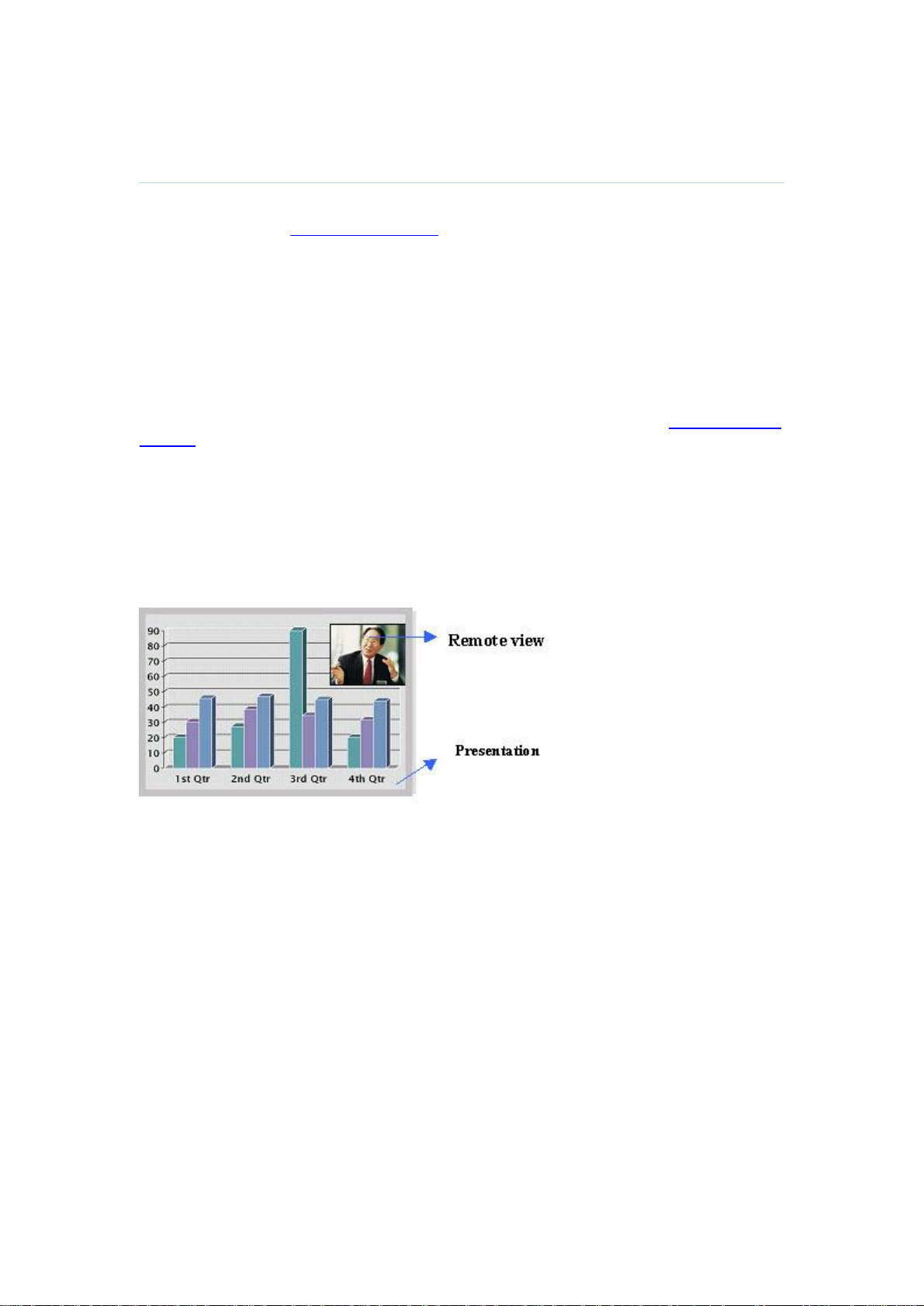
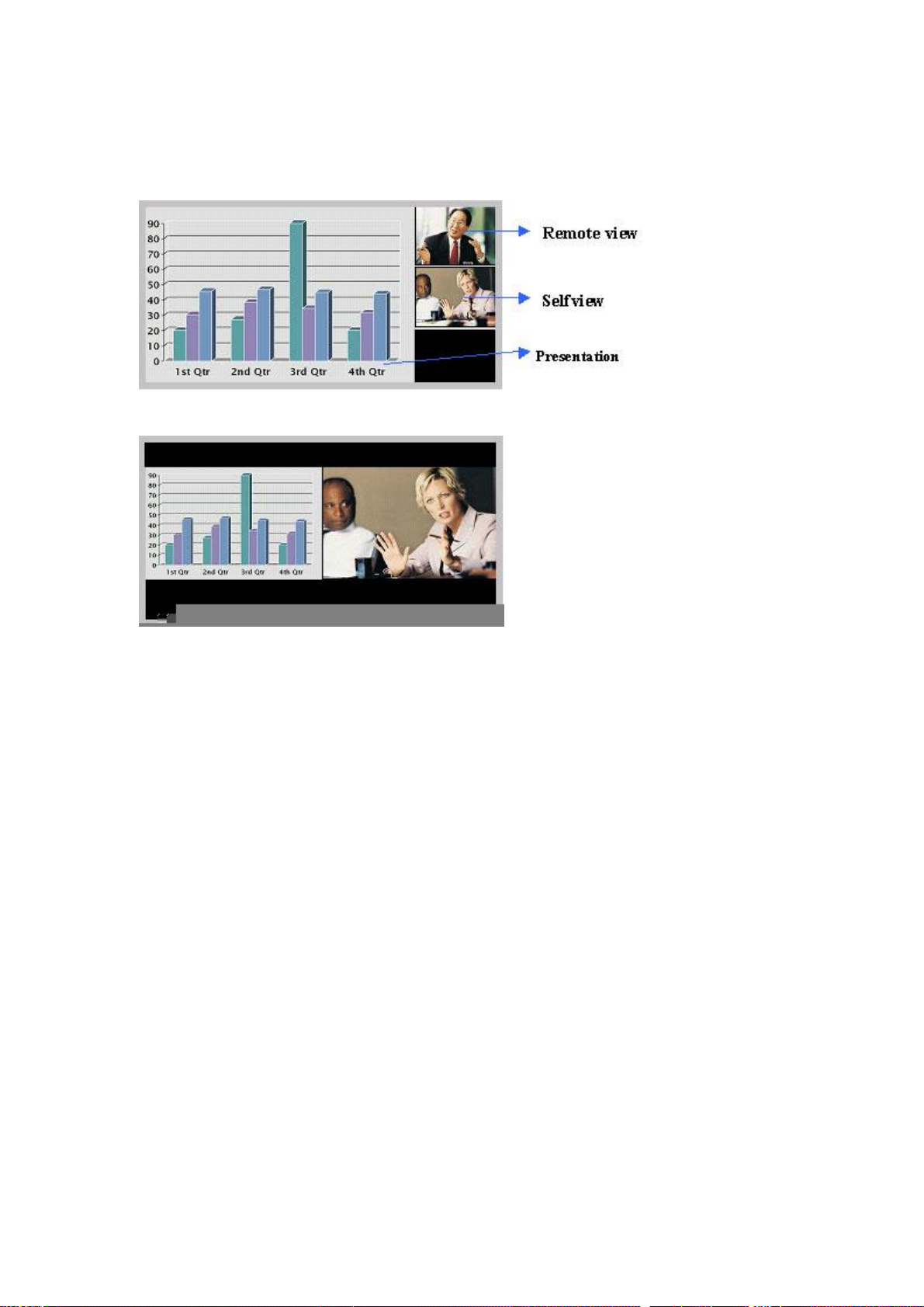
3.11.5 Duo VideoTF/H.239
3 General Use
(Optional feature)
With Duo Video you have the opportunity to show two different live video streams
simultaneously, main video and Duo Video. This is handy when showing a presentation. You
see the live presentation and the live video of the presenter simultaneously. When you start a
presentation, Duo Video starts automatically if both local and remote system supports Duo
Video. If one of the systems does not support Duo Video, no Duo Video will be established
and your presentation will be showed on your main video.
Example:
Start a meeting with main camera as video source. Press the presentation key on the
remote control to start a PC presentation.
PC will appear as Duo Video in addition to main camera. End the Duo Video presentation
by pressing presentation key again.
In Presentation Settings (see chapter 4.3 Presentation Settings), you can put Duo Video to
Manual. That means that Duo Video will not start automatically.
Example:
Start a meeting with main camera as video source. Press the presentation key on the
remote control to start a PC presentation.
A dialog box appears where you can choose to show PC as Duo Video or not. This is
handy if you not always want to use Duo Video.
Duo Video and Bandwidth
Using Duo Video, the quality will automatically downspeed to the optimal bandwidth. This
means that you need higher quality to allocate enough bandwidth for the two video streams.
Duo Video borrows bandwidth from main video. When Duo Video is closed, the bandwidth is
returned to the main video.
Controlling camera, changing video source and camera presets in a Duo Video call.
When selecting the Document Camera or PC, the system will automatically request floor
when connected to a MCU conference as MultiSite host or connected to an external MCU.
The main monitor will display incoming video and the 2nd monitor will display outgoing video
with Duo Video in full. Outgoing main video will be displayed in PIP on main monitor. For a
single monitor system, the Duo Video will be shown in full screen and the incoming video in
PIP. Most Duo Video sources are not possible to control with move camera and presets.
Move camera and presets will therefore work on the main camera also when you have Duo
Video, with one exception. If you use a second camera (aux) as Duo Video, move camera
and presets will work on Duo Video. If you want to control the main camera, press Move
Camera from the main menu and choose Near End Camera.
45

TANDBERG 1500 MXP
3.11.6 Take New Snapshot
The system can take a snapshot of your live video. Snapshot is handy when you are in a call
with a system that does not support Duo Video. Use Snapshot to show a snapshot of your
presentation and continue the meeting with main camera.
How to use snapshot:
You find Take New Snapshot in the Presentation menu. Press OK to take a snapshot.
Snapshot is found on the Star key on the remote control. Press Star and you take a
snapshot of the current video source (current video is default snapshot source). You
can change snapshot source in Control Panel\Administrator Settings\Presentation
Settings, see chapter 4.3 Presentation Settings. Note that snapshot does not work
when you are in an input field in the menu (the star key is then used to write the star
sign).
Note that Take New Snapshot is only available when you are in a call.
3.11.7 Display Snapshot
The system stores the last sent or received Snapshot. The snapshot is deleted automatically
after the call.
How to display snapshot:
To view a stored snapshot, choose Display Snapshot in the Presentation menu.
Press the Display Snapshot button again to deselect it. When disconnecting the call,
the stored snapshot will be erased.
When receiving a snapshot, the snapshot is displayed in full screen. Press OK to
escape from the snapshot. The last sent or received snapshot will be stored in the
graphics memory.
Note that Display Snapshot is only available when you have a stored snapshot.
46

3.12 MultiSite Services
3 General Use
A Multipoint Control Unit (MCU) enables several sites to participate in the same conference.
In TANDBERG's embedded MCU, MultiSite, you can have a maximum of 4video- and 3
telephone-participants including yourself (the host). The participants are tiled up on the
screen and are on display simultaneously in a Split Screen. During a MCU conference, the
status line will provide information about the conference.
You can make a MultiSite conference in different ways. The MultiSite Services vary
depending on how you make the call.
Using the system’s internal MCU, MultiSiteTF
The system has an optional built-in MCU, which is called MultiSite. It supports up to 4 video
calls and 3 telephone calls including yourself. The MultiSite supports both Split Screen and
Voice Switched mode.
With MultiSite, you have the following services:
Request/Release Floor
Assign Floor To Participant/Release Floor From Participant
Terminal Names
Layout (Auto/4 Split/3+1 Split/Voice Switched)
Using an external MCU that supports Chair Control (H.243)
With an external MCU that supports H.243, you have the following services:
Request/Release Floor
View Participant/End View
47

TANDBERG 1500 MXP
Chair Control
If you take Chair control, you get the following services:
Release Chair
Assign Floor To Participant/Release Floor From Participant
Disconnect Participant
Terminate Meeting
Using an external MCU that does not support Chair Control
With an external MCU that does not support H.243, you have the following services:
Request/Release Floor
Terminal Names
3.12.1 Request Floor and Release Floor
When requesting floor, your video will be broadcasted in full screen to all other participants in
the conference. Request Floor is useful when you want to speak or display something in front
of all participants. Therefore, floor will automatically be requested when taking a Snapshot or
Selecting Document Camera or PC.
Release Floor when you are done and make the floor available for other participants in the
conference. An indicator appears when you have floor and disappears when you release
floor.
How to use Request and Release Floor:
1. Open the Main Menu by pressing OK.
2. Choose MultiSite Services and press OK.
3. Choose Request Floor and press OK. A Floor indicator will appear when you have
floor.
4. When done, press the same button again, which now means Release Floor. The
Floor indicator disappears.
48

3.12.2 MultiSite Layout
3 General Use
(Only supported by TANDBERG MultiSite)
With a TANDBERG MultiSite you can choose between the layouts: Auto Split, 4 Split, 5+1
Split and Voice Switched view. Auto Split displays all participants on the screen
simultaneously. 4 Split displays the 4 last speaking Participants. 5+1 Split displays the
speaking participant in a big picture and the other participants in small pictures. Voice
Switched mode displays the participant that is speaking in full screen. Switch between these
picture modes using the MultiSite Layout menu.
49

TANDBERG 1500 MXP
3.12.3 Terminal Names
Choose Terminal Names to see a list of the participants of the MultiSite conference. Press
Cancel to go back.
3.12.4 Chair Control
(Not supported by TANDBERG MCU or MultiSite)
As chairman, you have access to more MultiSite Services. Select Chair Control to assume the
role of chairman of the conference. Select Release Chair to end the role as chairman. A Chair
indicator appears when you have Chair and disappears when chair is released.
3.12.5 Assign Floor and Release Floor from Participant
Assign Floor allows the chairman to select which of the conference participants that is to be
broadcasted to all other participants.
3.12.6 View Site and End View
(Not supported by TANDBERG MCU or MultiSite)
View Site allows you to view any participant in the conference regardless of whom having
floor and chair. Choose End View to go back to normal.
3.12.7 Disconnect Participant
Disconnect Participant allows the chairman to disconnect any participant in the conference. In
a multipoint call, this is equivalent to disconnecting a participant from the end call menu.
3.12.8 Terminate Meeting
Terminate Meeting allows the chairman to terminate the conference altogether. In a MultiSite
call, this is equivalent to pressing End All Calls from the end call menu.
50

3 General Use
3.12.9 More about MultiSite (embedded MCU)
(Optional Feature)
Calling in to a MultiSite
Any system can be part of a MultiSite conference by calling in to a MultiSite. The dial-in
numbers to the MultiSite depends of the network that is used.
To dial in to the MultiSite on IP:
Dial the IP Number or the IP Address of the system. All sites can dial the same
number.
To dial in to the MultiSite on ISDN-PRI:
Dial the ISDN number of the system. All sites can dial the same number.
To dial in to the MultiSite on ISDN-BRI:
The MultiSite has specific numbers for each call that participates in the conference.
To find the dial-in numbers for the MultiSite, choose Information from the main menu
and open System Information from the bottom menu line.
Site 2 must dial MultiSite Number 2.
Site 3 must dial MultiSite Number 3.
Site 4 must dial MultiSite Number 4.
And so forth
Receiving calls to a MultiSite
When the MultiSite receives incoming calls you can accept or reject it. Pressing the green key
is equivalent to pressing Accept. Pressing the red key is equivalent to pressing Reject.
End a MultiSite Call
Ending a MultiSite Call is not very different from ending a normal point-to-point call. Use the
red key on the remote control or End Call from the main menu. The end call menu lists all the
calls that participate in the conference. To end a single call, select the call, press OK or the
red key on the remote control. To end all calls, press the End All Calls button in the menu.
Duo Video in MultiSite calls
In a MultiSite call, the MultiSite can transmit the Duo Video and/or H.329 to the other
participants that support Duo Video and/or H.329. This means that any participant can send
Duo Video and the MultiSite will transmit it to the other participants. The participants that do
not support Duo Video or H.329 will only receive Main Video.
Mix ISDN/LAN
A conference can consist of any combination of ISDN/IP sites.
51

TANDBERG 1500 MXP
3.13 Control Panel
The Control Panel contains the features:
User Guide
Streaming
Far End Control
Camera Preset
Camera Tracking
Text Chat
System Information
Administrator Settings
Restart
3.13.1 User Guide
The on screen user guide takes you through a quick step-by-step introduction to
videoconferencing. It gives the user basic skills in how to use the system.
52

3.13.2 Streaming
3 General Use
Streaming lets you broadcast your meeting to participants on web. The web participants can
listen to the meeting, see snapshots, but not participate themselves. Snapshots of current
stream (if MultiSite), selfview, far end and DuoVideo streams are accessible via http. See
Appendix 7 for descriptions of the possible snapshot files.
How to use Streaming:
1. Choose Streaming from the Control Panel to open the Streaming menu.
2. Press Start Streaming from the menu line.
3. Press Stop Streaming to end streaming. Streaming will also end when you disconnect
the call.
4. Press Streaming Settings if you want to change streaming settings (see Streaming
Settings below)
How to view streaming from a PC:
1. After streaming is started, an easy way to view the streamed audio/video is to start
your Web browser and enter the IP-address of the streaming system.
2. After the Web page of the system is shown, click on Streaming. Alternatively, enter
http://<codec ip-address>/stream.sdp
Streaming Settings
Address
Address Port
TTL/Router
Hops
Streaming
Source
Address is defined as the IP-address of a streaming client,
streaming server or a multicast address. Giving an address in the
range 224.0.0.1-239.255.255.255 will broadcast the stream to any
host that has joined the specified multicast group. Specifying normal
broadcast address 255.255.255.255 will broadcast to any members
on the LAN.
If several codec’s are streaming to the same IP-address, different
ports have to be used in order for the client to know which stream to
receive. If the first codec streams on port 2240 and the second
codec on port 2250, the client has to specify which port to listen to.
Video is transmitted on the specified port; audio is transmitted on the
port number 4 above the specified video port, in this case 2244 and
2254.
This is used for streaming data to limit how many routers the data
should pass before it is rejected. If TTL is set to 2, data will not
traverse more than 2 router hops.
Auto: Enables streaming of both local and far end video.
Selection of which site to be streamed is done using voice
switching (the site that speaks is streamed).
Local: Only the local video will be streamed.
53

TANDBERG 1500 MXP
Local and far end audio is always streamed.
Allow Remote
Start
Announcements
Video Rate
Streaming
Password
Defines the Video streaming rate from the system. Range is 16 kbps
- 320 kbps. In addition, audio (G.711) streaming rate is 64 kbps,
providing a maximum streaming rate of 384 kbps.
Set password so that only participants entering correct password will
be able to view the streaming session. Entering a password will
prevent unauthorized people from accessing the streaming session.
Remote: Only the far end video will be streamed.
On: Streaming can be started from external user interfaces
like the Web-browser or Telnet session.
Off: Streaming can only be started from the Video
Conferencing System using the remote control, or by using
the Data port. This will prevent activation of streaming using
Web browser or Telnet sessions. See also Password
section below
On: The codec will announce to the network that it is
streaming. This enables a streaming client (e.g. a PC) to
connect to the codec’s streaming session. Used by Cisco
IP/TV.
Off: No announcement packets will be transmitted.
3.13.3 Far End Control
It is possible to get some control of the far end system. This means that you can control your
conference partner’s camera, video sources and presets. You can also request a snapshot
from the far end side. Enabling Far End Control in the Control Panel will put the system in Far
End mode and camera control, camera preset, presentation, and snapshot will work on the far
end camera.
Far End Control only works when you are in call and if the far end side supports H.281 (Far
End Camera Control). You can prevent others from controlling your system by setting Allow
Far End Camera Control to Off in Control Panel\Administrator Setting\General\Permissions
(chapter 4.1.7 Permissions).
How to use Far End control:
1. Open the Control Panel.
2. Enable Far End Control by selecting the Far End button in the Control Panel. A green
circle indicates that the Far End button is activated.
3. Now you are in Far End mode and can use camera control, camera preset,
presentation and snapshot for the far end.
4. To turn Far End control off, go to the control panel again and press Far End again.
The green circle disappears.
54

3 General Use
Far End Camera Presets
Far End Camera Presets works just like your own camera presets. When Far End is on, use
the number keys to activate far end camera presets. You are however not allowed to save far
end camera presets.
Far End Presentation
Pressing the Presentation key or choosing a presentation from the presentation menu while
Far End is on, will result in opening a far end presentation. Be aware of that the far end video
sources may not correspond with the buttons in the presentation menu. If you press
Document Camera, the far end side might have another video source on this input.
Request snapshot from the Far End
You can request a snapshot from the far end side. Put the system in Far End mode and press
Snapshot on the remote control to take a snapshot of the current far end video (current is
default snapshot source).
3.13.4 Camera Preset
(not for TANDBERG 1500 MXP)
In the Display menu you find Display Presets and Save Preset
Display Presets displays camera presets 0-9 in a menu. The disabled
buttons represent camera presets that are not saved yet. Use arrow keys to
select a camera preset.
Save Preset will take you to the save presets menu. Enter a number and
you will save the current camera position. Note that you can save camera
presets by pressing a number for 1 second. Use the Save Preset menu if
you need to save presets 10-14 (see chapter 3.10.3 Camera Presets).
3.13.5 Camera Tracking
(not for TANDBERG 1500 MXP)
Through Camera Tracking and the use of two or three microphones, the camera can
automatically position itself on the current speaker. Before using camera tracking, the camera
positions used must be stored at Preset 7 (Mic1) and/or Preset 8 (Mic2).
How to use Camera Tracking:
1. Open the Control Panel.
2. Enable Camera Tracking by choosing Camera Tracking in the Control Panel. An
indicator will appear as you enable Camera Tracking.
3. End Camera tracking by deselecting the button. Camera Tracking will also end if you
activate a Camera Preset or move the camera manually with the arrow keys.
55

TANDBERG 1500 MXP
Example: You have placed Microphone 1 on the table. Where should you position the
camera for Preset 7?
The camera position stored at Preset 7 must be related to Microphone 1. Therefore all
participants who are located closest to Mic1 should be included in the Preset 7 camera
position etc. When camera tracking is activated and a person close to Mic1 speaks, Preset
7 will be automatically selected.
When activating another video source (for instance document camera), camera tracking will
be temporarily disabled until you re-select Main Camera or a Main Camera Preset.
The camera tracking speeds may be altered in the Video Settings menu in Administrator
Settings, see chapter 4.6.1 Camera Tracking Mode for further details.
A Voice Detector makes the system more tolerant of noise and ensures the camera not to be
moved by noise such as paper shuffling, etc.
Note that pressing Mic Off will temporarily disable camera tracking until you turn on the
microphone again.
3.13.6 Text Chat
While in an ISDN or IP call to another system supporting Text Chat (T.140), select Text Chat
from the Control Panel. Enter text in the displayed window.
How to use Text Chat:
1. Choose Text Chat from the Control Panel to open the Text Chat window.
2. Enter text with the number keys like on a mobile phone. The text is sent to the far end
continuously letter by letter.
3. Press OK to end Text Chat and escape from the text chat window.
3.13.7 System Information
In System Information you find all information about the system.
The most useful information for users is listed first:
System Name
My ISDN Number
My IP Number
My IP Address
MultiSite Number(s)
Software Version
Option Installed
Serial No
MAC address
Ethernet Speed
56

Network
In system information you also find:
Call Status
Channel Status
View Administrator Settings
For more information, see chapter 4.9 Diagnostics.
3.13.8 Administrator Settings
3 General Use
Administrator Settings contains the configuration of the whole system. It is recommended to
password protect Administrator Settings to prevent occasional users to make changes to the
system. See Chapter 4 Administrator Settings for further details.
3.13.9 Restart
Restart the system by pressing the Restart button. You are prompted with a dialog box
saying: Do you want to restart the system? Press OK to restart, press Cancel (X) to abort.
57

4 Administrator Settings
Administrator Settings contain all the settings of the system. Making changes to Administrator
Settings will change the behavior of the system. It is recommended to password protect the
access to Administrator Settings to prevent occasional users from making crucial changes to
the system, see chapter 4.2.9 Administrator Password.
Administrator Settings contain:
General
Menu Settings
Presentation Settings
Call Quality
Audio
Video
Security
Network
Diagnostics
58

4.1 General Settings
4 Administrator Settings
When installing the system, go through the General Settings menu to ensure that you have
the right settings for your system, see chapter 2.4 System Configuration.
General Settings contain:
Language
System Name
Autoanswer
Max Call Length
Global Phone Book Settings
Permissions
Screen Settings
Software Options
4.1.1 Language
The system supports 13 different languages for its on-screen menus; English, German,
French, Norwegian, Swedish, Italian, Spanish, Portuguese, Chinese Simplified, Chinese
Traditional, Japanese, Russian and Korean. Select the preferred language and press OK to
save.
59

TANDBERG 1500 MXP
4.1.2 System Name
System Name identifies the system:
on the welcome page.
during an MCU conference call.
when using the Web-interface.
when the codec is acting as an SNMP Agent.
towards a DHCP server.
as an H323 ID. Other systems can call in using this name instead of IP-number/IP-
address.
System Name is blank by default. System name can be alphanumeric and up to 50
characters long. Follow the installation procedure to enter a System Name.
4.1.3 Dual Monitor
(not for TANDBERG 1500 MXP and 2000 MXP)
TANDBERG systems can be used with both one or two monitors. If you use two monitors,
make sure that Dual Monitor is set to On.
On
Off
Selfview, snapshots and Duo Video will be displayed on the second monitor.
The second monitor shows selfview only.
4.1.4 Autoanswer
The auto answer setting decides whether an incoming call is put through automatically or
manually.
On
On+MicOff
Off
The system will automatically answer all incoming calls.
The system will automatically answer all incoming calls and switch the
microphone off when the call is connected. Press Mic Off to switch the
microphone on.
You must manually answer all incoming calls by pressing OK or the Call
key.
60

4.1.5 Max Call Length
4 Administrator Settings
This feature will automatically end both incoming and outgoing calls when the call time
exceeds the specified Max Call Length. Max Call Length can have the following values: 0-999
(minutes), where 0 means off.
4.1.6 Global Phone Book Settings
Global
On
Off
IP address
Enter the IP address of the management system that provides the Phone Book.
Path
The Path indicates the function of the management system.
Global Phone Book is available in the menu.
Global Phone Book is hidden from the menu and is unavailable for users.
4.1.7 Permissions
Permissions contains settings for incoming MCU Calls, incoming telephone Calls, Far End
Control and Fallback to Telephony.
Access Code
An access code will help you control the use of the system. All users must enter a code to
identify themselves and the call will be charged on their account. Access Codes are handy for
group systems where there are more users or divisions that share the costs of using the
system. Access Code can be put to On and Off.
On
Off
When making a call, an Access Code dialog box will be shown. The user must
enter the correct password in order to put the call through.
No password is necessary to make a call.
61

TANDBERG 1500 MXP
Incoming MCU Calls
On
Off The system will not accept incoming calls when you are in a call.
Incoming Telephone Calls
On
Off
Far End Control
On
Off
Fallback to Telephony
When dialing a number and the system fails to place a video call to the number dialed, the
system will attempt to place a telephone call if Fallback to Telephony is enabled.
On
Off
When you are in a call, the system will provide visual and audible indications of
an incoming call and ask you to accept/reject the call.
The system will accept incoming telephone calls.
The system will not accept incoming telephone calls. This is useful to prevent
incoming calls from systems other than videoconferencing systems.
The far end will be able to:
• Control your camera
• Select your video sources
• Activate your camera presets
• Request snapshots
The far end can access none of the four features above on the local system. You
will however still be able to control the camera on the far end.
Enables fallback from video calls to telephone calls.
Disables fallback.
4.1.8 Screen Settings
Picture Layout
The Advanced Picture Layout is related to the Layout button on the remote control and it can
be used at any time to change the screen layout. For wide screen systems POP mode is
recommended. You will get optimized picture layouts for wide screen by pressing the Layout
button on the remote.
Picture in
Picture (PIP)
62
Pressing the Layout button on the remote will result in an extra picture in
smaller view (Picture in Picture. Press the Layout button to move it and

finally hide it.
Picture
outside
Picture
(POP)
Pressing the Layout button on the remote will result in a smaller view
placed outside the big picture. Press Layout once more to get emulated
dual monitor view. Press Layout again to go back to normal full screen
view.
Pressing the Layout button on the remote will result in one large image
and one or two smaller pictures placed outside the big picture. Press
Layout once more to get a side by side view. Press Layout again to go
back to normal full screen view.
4 Administrator Settings
Example of Picture in Picture.
Example of Picture outside Picture (wide screen).
63

TANDBERG 1500 MXP
VGA Monitor Format
To fully leverage your wide screen display, activate the Native 16:9 format by setting the VGA
Monitor Format to Wide. Note that you should only change this setting if your VGA monitor is
a wide screen (16:9) monitor or projector. The VGA and DVI output will then be optimized for
Wide Screen VGA display.
Normal
Output format is optimized for Normal VGA monitors (4:3)
Wide
Output format is optimized for Wide VGA monitors (16:9)
Wide screen VGA or TV monitor in Normal (stretched) mode.
Wide screen VGA or TV monitor In Wide (native) mode.
VGA Out Quality
The supported range of VGA formats will be optimized for the VGA display monitor based on
the source image.
VGA Out Quality enables the user to change the preferred format for the DVI/VGA output. It is
recommended to keep this setting in Auto unless your screen doesn’t support some of the
XGA or SVGA formats the system is using. Note that the VGA Out port support VESA Power
Management.
Auto
VGA output format will be optimized dependant of the video source
format, refresh and of the EDID information available.
Supported formats are:
SVGA (800x600) 75Hz
SVGA (800x600) 90Hz
XGA (1024x768) 60Hz
XGA (1024x768) 75Hz
SVGA
VGA output format is forced to SVGA format (800x600) 75Hz
64

4 Administrator Settings
800x600 75Hz
XGA
1024x768
VGA output format is forced to XGA format (1024x768) 60Hz
60Hz
PC Picture Format
PC Picture Format setting only takes effect when TV or VGA Monitor Format is set to Wide.
Use this setting to determine if you want your PC presentations to be shown stretched in full
screen, or with correct aspect ratio using part of the widescreen display
Normal
VGA output will have 4:3 aspect ratio on wide screen monitor.
Wide
VGA output will utilize the wide screen monitor at full.
PC presentation shown in Normal (correct ratio) mode.
PC Presentation shown in Wide (stretched) mode.
65

TANDBERG 1500 MXP
4.1.9 Software Options
The system requires a valid option key to activate MultiSite and/or Presenter functionality. In
order to activate additional bandwidth, you need to enter a bandwidth key. A restart of the
system is required after entering a new option and/or bandwidth keys. If the key is invalid, the
original key will be used.
The following options are available:
1. No option
2. Presenter
3. MultiSite + Presenter
4. Bandwidth options
66

4.2 Menu Settings
4 Administrator Settings
Menu Settings contain the settings:
Menu Timeout In Call
Welcome Menu
Welcome Picture
Logo
Display Welcome Text
Welcome Text
Administrator Password
4.2.1 Menu Timeout In Call
Main menu appears on the bottom line of the screen. Set Menu Timeout In Call to On if you
want the menu to time out automatically when you are in a call.
On
Off
The menu will time out automatically after 15 seconds if there is no activity on the
remote control. Menu timeout does only apply when you are in a call. Outside a
call, the menu will not time out.
The menu will not time out automatically. Press Cancel (X) to hide the main
menu manually.
67

TANDBERG 1500 MXP
4.2.2 Welcome Menu
The Welcome Menu contains the Main Menu, System Status, your System Name and dial in
numbers.
On
Off
The Welcome Menu is shown when the system wakes up from standby mode.
The Welcome Menu is not shown when the system wakes up from standby
mode. Press the OK button to open the welcome menu.
4.2.3 Welcome Picture
The Welcome Picture is what you see in the background of the welcome menu.
Selfview
Off
Selfview is shown in the background of the welcome menu. In most cases this
means that main camera is displayed and you can see the video image of
yourself.
No picture is shown in the background of the welcome menu.
4.2.4 Logo
It is possible to upload a company logo to the system. For more information about how to
upload a Logo, see Appendix 7. Put the Logo settings to On to display the logo.
On
Off
Choose On if you want the company logo to appear in the background of the
welcome menu.
The logo is not displayed.
68

4.2.5 Menu on TV
4 Administrator Settings
(not for TANDBERG 1500 MXP and 2000 MXP)
The Menu on TV setting decides if the menu shall be displayed on the TV screen or not. For
optimal layout of the menu, 'Menu on TV' should be Off if 'Menu on PC' is On and vice versa.
On
Off
The menu is available on the TV screen.
The menu is not available on the TV screen.
4.2.6 Menu on PC
(not for TANDBERG 1500 MXP and 2000 MXP)
The Menu on PC setting decides if the menu shall be displayed on the PC (VGA screen)
screen or not. For optimal layout of the menu, 'Menu on TV' should be Off if 'Menu on PC' is
On and vice versa.
On
Off
The menu is available on the PC screen.
The menu is not available on the PC screen.
4.2.7 Display Welcome Text
The welcome text displays your system name and dial in numbers by default. It is possible to
hide this information by choosing Display Welcome Text Off.
On
Off
Welcome text is displayed on the welcome menu.
Welcome text is not displayed on the welcome menu.
69

TANDBERG 1500 MXP
4.2.8 Welcom
70

4.3 Presentation Settings
4 Administrator Settings
Presentation Settings contain:
Presentation Start
H.239
Call Video Source
Presentation Source
Snapshot Source
Auto-Display Snapshot
PIP Appearance
PIP Placing
VNC Settings
4.3.1 Presentation Start
If your system has Duo Video capabilities, you can show two video streams at the same time
(see also chapter 3.11.5 Duo Video). Presentation Start is Auto by default. This means that
you will start Duo Video (a second video stream) automatically when starting a presentation.
Duo Video requires the Presenter Option and H.263 video. To check which options are
installed, see the System Information menu in Control Panel.
Manual means that you manually choose if you want to start Duo Video or not every time you
start a presentation.
Auto
Duo Video starts automatically when you start a presentation (in other words,
when you choose a second video source). If your system or the far end system
is not capable of Duo Video, you will not use Duo Video, but rather send the
presentation source as your Main Video
71

TANDBERG 1500 MXP
Manual
When starting a presentation, a dialog box appears asking if you want to start
Duo Video. In this way you can choose manually if you want to use Duo Video
or not.
4.3.2 H.239
H.239 supports transmission of two video streams. It combines elements of Duo Video and
People+Content. If H.239 is disabled you will still be able to start TANDBERG Duo Video.
Enabled:
Disabled:
Enables H.239
Disables H.239
4.3.3 Call Video Source
The Call Video Source is the default video source you would like to use in a call. If you use
Main Camera as Call Video Source, the system will start with Main Camera every time you
make a call, regardless of what the previous video source was.
Example: What is the advantage of setting Call Video Source to Main Camera?
When you are not in a call, you can work with the screen as a normal PC screen. When
you make a video call, the system will automatically change to Main Camera. When you
receive a call, the system will also automatically change to Main Camera, preventing
that the caller will see your PC image.
You can change Call Video Source to Main Camera, PC or Current. Choosing Current will
result in the last used video source.
4.3.4 Presentation Source
The Presentation Source is connected to the Presentation button on the remote. Pressing the
Presentation button will put the Presentation Source on display. Presentation Source is PC by
default. You can change the Presentation Source to any video source and none. Choosing
none results in opening the Presentation menu when pressing the Presentation key.
72

4.3.5 Snapshot Source
4 Administrator Settings
When you take a Snapshot, you get a snapshot of the Snapshot Source. Current is the
default Snapshot Source. This means that you take a snapshot of the video source that is
currently active.
You can change the Snapshot Source to any video source. In this way you can program the
snapshot key to apply only for PC for instance. Press Snapshot and you will take a PC
snapshot regardless of what video source that is currently active.
4.3.6 Auto-Display Snapshot
Select Auto to automatically display a received snapshot. Turn Auto-Display Snapshot Maual
if you wish not to have them displayed on the screen when they are sent or received. The
snapshots will be sent and received, but not displayed. With Auto-Display Snapshot set for
Manual, you must enter the Presentation menu to display a snapshot.
Auto
Manual
A sent or received snapshot will automatically be displayed on the screen.
A sent or received snapshot will not be displayed on the screen. To see the
snapshot, choose Display Snapshot in the Presentation menu.
4.3.7 PIP Appearance
A Picture in Picture (PIP) is a smaller picture placed in one of the corners of the screen. The
PIP enables you to see an extra picture in your video conference.
Auto
On
Off
PIP Auto means that Picture In Picture will appear automatically when it is
suitable. A picture in picture is nice when you use Duo Video and you need an
extra window to see all the pictures. You can of course show or hide the PIP with
the Layout button on the remote anytime.
PIP On means that a Picture in Picture will always be displayed.
PIP Off means that PIP is not displayed automatically.
73

TANDBERG 1500 MXP
4.3.8 PIP Placing
PIP Placing lets you decide where the PIP shall appear. You can of course move the PIP with
the Layout button on the remote anytime.
Top
Right
Bottom
Right
Bottom
Left
Top
Left
PIP is placed in the Top Right corner.
PIP is placed in the Bottom Right corner.
PIP is placed in the Bottom Left corner.
PIP is placed in the Top Left corner.
4.3.9 VNC Settings
VNC Settings is necessary when using a VNC presentation. See chapter 3.11.4 PC Soft
Presenter and VNC for more about how to use VNC.
Address
Display
Number
Password
The IP-address of the PC with the VNC software installed. To find the IPaddress of the PC, place the mouse pointer on the VNC program icon in the
lower right corner of the Windows taskbar. You can also select Command
Prompt from the Startup-menu\Run and type cmd then enter. This will open
a command window and from here. Type “ipconfig” and press enter.
The display number for VNC is 0 and upwards. If you are using WinVNC,
double-click on the icon on the taskbar to view WinVNC properties. This
number should correspond with Display Number in this menu.
Enter the same password as specified in WinVNC properties. The
password will be shown as asterisk signs (*) the next time you enter the
menu.
74

4.4 Call Quality
4 Administrator Settings
Call Quality contains the settings:
Video Algorithm
Audio Algorithm
AAC-LD 128kbps
Natural Video
Video Quality
Default Call Settings
4.4.1 Video Algorithm
The system will automatically select the best video algorithm based on the video source and
the capabilities of the remote system. Use this menu to disable video algorithms in case you
have interoperability issues calling other systems.
H.264
H.263
H.261
Bandwidth efficient video compression and decompression.
Normal video compression and decompression.
Legacy video compression and decompression. The system will always have
H.261 enabled. Therefore it is impossible to uncheck H.261.
75

TANDBERG 1500 MXP
4.4.2 Audio Algorithm
The system will automatically select the best audio algorithm based on the call rate and the
capabilities of the remote system. Use this menu to disable audio algorithms in case you want
to remove “low quality” audio, or if you have interoperability issues calling other systems.
G.722
G.728
G.711
G.722.1
AAC_LD
Call Rate vs Audio algorithms selected
Modify/remove algorithms used by uncheck the different audio algorithms
Automatically preferred audio algorithms on call rates up to and including 192kbps
1. G.722.1 (24kbps or 32kbps)
2. G.728 (16kbps)
3. AAC-LD (56kbps or 64kbps)
4. G.722 (48kbps, 56kbps or 64kbps)
5. G.711 (48kbps, 56kbps or 64kbps)*
6. AAC-LD (48kbps or 128kbps)
Automatically preferred audio algorithms on call rates above 192kbps
1. AAC-LD (128kbps)**
2. AAC-LD (64kbps or 56kbps)
3. G.722 (64kbps, 56kbps or 48kbps)
4. G.722.1 (32kbps or 24kbps)
5. G.728 (16kbps)
6. G.711 (64kbps, 56kbps, 48kbps)*
7. AAC-LD (48kbps)
* AAC-LD, G722 and G711 at 64kbps are used for audio in H323 (IP) calls only
** Dependent that the call rate is above the AAC-LD 128 threshold.
High quality audio (7 kHz at 48kbps, 56kbps or 64kbps)
Compressed normal quality audio (telephone quality, 3.1 kHz at 16kbps)
Normal quality audio (telephone quality 3.1kHz at 64kbps). This audio
algorithm is mandatory for video conferencing equipment and is impossible to
uncheck.
Compressed high quality audio (7 kHz at 24kbps and 32kbps).
CD-quality audio, MPEG-4 Advanced Audio Coding Low Delay (20 kHz,
stereo at 128kbps20kHz, mono at 64kbps).
76

4 Administrator Settings
4.4.3 AAC-LD 128kbps (stereo audio)
Specify a call rate for 128kbps AAC-LD. From this call rate and above, "128kbps AAC-LD" is
available. On lower call rates "64kbps AAC-LD" is available.
Stereo audio requires twice the bandwidth as mono CD-quality audio. Therefore we
recommend to enable stereo audio on high call rates only. To enable stereo CD-quality audio
you need to specify a call rate for when stereo automatically should be enabled. On lower call
rates, mono CD-quality audio "64kbps AAC-LD" will be enabled.
4.4.4 Natural Video
Choosing Natural Video will enable 60 fields per second true interlaced picture for high motion
video.
Auto:
Off:
Custom:
Natural Video Auto will enable transmission of Natural Video from 768 kbps
and above. Reception of Natural Video is in this case always enabled.
Natural Video Off will disable both transmission and reception of Natural
Video.
384 kbps and above to 1920 kbps and above
4.4.5 Video Quality
The different video sources need different Video Quality Settings. Main Camera, VCR, AUX
and Split Screen have Motion as default. PC, Document Camera and VNC have Sharpness
as default.
Motion:
Sharpness:
Auto:
Optimized for smooth motion video (CIF/SIF for low bandwidths, iCIF/iSIF
for high bandwidths).
Optimized for sharp video (4CIF/4SIF, SVGA, XGA).
The system chooses the best of Motion or Sharpness depending on
picture layout and bandwidth.
77

TANDBERG 1500 MXP
4.4.6 Default Call Settings
Default Call Settings are connected with Call Settings in the call menu. If you leave Call
Settings unchanged when making a call, the system will use the Default Call Settings in the
call. See chapter 3.5.4 Call Settings for more information.
In addition to the call Settings Call Type, Net, Bandwidth and Restrict (56k), you also find
settings for H.320 Auto bandwidth and H.323 Auto bandwidth in Default Call Settings.
78

4.5 Audio
4 Administrator Settings
Audio contains the settings:
Inputs
Outputs
Echo Control
Stereo Settings
Audio Levelling (AGC)
Alert Tones and Volume
4.5.1 Inputs
Mic and Audio input L-R (VCR Left/Right)
By default, all inputs are enabled. Just plug in an audio source and it is active. Audio inputs
that are On will automatically be mixed. Unconnected inputs will automatically be muted.
Select Off to prevent audio/noise from connected but unused inputs.
Audio inputs L-R (VCR Left/Right) are intended for connection to a VCR, DVD player or PC
audio output. They can also be connected to other external playback devices. As there is no
acoustic echo canceller on these inputs they should not be connected to any microphones.
The audio entering these inputs will be heard from the local speaker as well.
VCR Ducking
If VCR Ducking is activated, the VCR audio level will be attenuated if someone talks
into the microphone or at the far end.
Level Settings
It is possible to adjust the audio input levels according to which audio equipment that is
connected. The on-screen audio level indicator will make it easier to set the correct input level
settings. The input level should be adjusted so that the average level reaches the preferred
level marker. The audio inputs are adjustable in steps of +1.5 dB from 0 dB to +22.5 dB.
79

TANDBERG 1500 MXP
The default level for the microphone is set to +3 dB.
Audio inputs VCR Left/Right are set to a default level which is adhered to by most
manufacturers of audio-visual equipment and is a level at which most audio-visual equipment
(CD-players, VCRs or DVDs) will work.
4.5.2 Outputs
(not for TANDBERG 1500 MXP and 2000 MXP, software version F1)
Audio Out
Audio out is internally connected to the monitor loudspeakers. The signal is a mix of audio
from far end and local end Audio in (VCR Left/Right).
If an output is Off, no audio will be sent to that output.
Level Settings
Adjust the audio output level to the loudspeakers.
The volume keys on the remote control also adjust the level of the audio output.
4.5.3 Echo Control
Microphone
The microphone input has an acoustic echo canceller. In addition to echo cancellation, the
system has built-in noise reduction (NR). NR reduces constant background noise (e.g. noise
from air-conditioning systems, cooling fans etc.). In addition, a high pass filter (Humfilter)
reduces very low frequency noise.
On:
Off:
On+NR:
Note that it is your echo canceller that improves the audio quality experienced by the other
site. When you hear an echo of your own audio it is most likely the far end’s echo
canceller that is malfunctioning.
Echo control is normally set to On to prevent the far end from hearing their
own audio. Once selected, echo cancellation is active at all times. The echo
canceller continuously adjusts itself to the audio characteristics of the room
and compensates for any changes it detects in the audio environment. If the
changes in the audio conditions are very significant the echo canceller may
take a second or two to re-adjust.
Turns off the echo canceller.
Activates both Echo Control and Noise Reduction.
80

4 Administrator Settings
Tips for improving the echo canceller performance:
It is recommended to place the microphone between 1 and 2 meters away from the
persons speaking.
Place the microphone as far as possible from noise sources.
Reduce the volume setting. Ensure that the loudspeakers do not distort the audio.
The echo canceller tries to estimate the echo path from the speaker system to the
microphones. Moving objects change this path, therefore try to avoid moving objects.
Be especially aware of large objects and objects placed close to either the
microphone or the speaker system as these objects will cause severe changes to the
echo path.
Avoid putting paper sheets etc. on the microphone.
Avoid moving the microphone or loudspeaker.
In the presence of low frequency noise, enable the noise reduction (NR).
4.5.4 Stereo Settings
(not for TANDBERG 1500 MXP and 2000 MXP, software version F1)
Stereo Input mode (stereo audio)
If Stereo Input mode is on, Audio in L/R (VCR Left/Right) will behave as a stereo input pair.
The VCR Ducking and AGC setting for Audio in R will in this case apply to both Audio in L
and R.
Audio out to the left loudspeaker will be a mix of Audio in L (VCR Left), the microphones and
the far end signal (left or mono), and Audio out to the right loudspeaker will be a mix of Audio
in R (VCR Right), the microphones and the far end signal (right or mono).
If Stereo Input Mode is off, Audio out to both loudspeakers will be a mix of Audio in L and R,
the microphones and the far end (mono or left+right).
4.5.5 Audio Levelling (AGC)
On
Off
Note that to ensure correct behaviour of the AGC, it is crucial that the levels on the input
connectors are adjusted correctly using the audio input level settings. The AGC will not
compensate for severe maladjustment of input levels.
When applying a weak signal in the presence of strong background noise, the AGC might
amplify the background noise as well as the signal. Therefore, in noisy environments, it is
advisable to turn the AGC off.
Select On to allow automatic adjustments (Automatic Gain Control) of audio
levels. When On, the AGC maintains the audio signal level at a fixed value by
attenuating strong signals and amplifying weak signals. Very weak signals, i.e.
noise alone, will not be amplified.
Audio levelling is not activated.
81

TANDBERG 1500 MXP
Example:
In most conferences, the participants will speak at different levels, and be at different
distances from the microphones. As a result, some of the participants would be harder to
hear than others. The AGC corrects this problem by automatically increasing the
microphone levels when “quiet” or “distant” people speak, and by decreasing the
microphone levels when “louder” people speak.
4.5.6 Alert Tones and Volume
Video Call Alert Tone and Telephone Alert Tone
To help distinguish between incoming video calls and ordinary telephone calls, it is
recommended to use different ringing tones for video calls and telephone calls.
Alert Volume
You may change the volume level for the selected ringing tone.
Alert Speaker
The system also has an internal, call-alerting speaker.
On
Off
Key Sound
On
Off
The internal speaker will warn you of an incoming call even though the monitor
may not be switched on.
The internal speaker is switched off.
There will be a sound indicator when pressing keys on the remote control.
There will be no sound when pressing keys on the remote control.
82

4.6 Video
4 Administrator Settings
Video contains the settings:
MCU Status Line
Floor to Full Screen
Web Snapshots
MultiSite Picture Mode
Video Name
4.6.1 Camera Tracking Mode
(not for TANDBERG 1500 MXP)
Slow:
Normal:
Fast:
Note that the Camera Tracking Mode entry will not be available if not using the WAVE
Camera.
The system waits a while before zooming in on a single person speaking.
Suitable when wide-angle images are preferred over close-up images.
Should be used in regular meetings.
The system quickly zooms in on a single person speaking. Suitable when
close-ups are preferred over wide-angle images.
83

TANDBERG 1500 MXP
4.6.2 MCU Status Line
On
Off
Auto
The MultiSite/MCU/DuoVideo indicators will be displayed and provide information
about the conference.
The MultiSite/MCU/DuoVideo indicators will not be displayed.
The MultiSite/MCU/DuoVideo indicators will be displayed for a few seconds and
then timed out. When grabbing the remote control, the indicators will be shown
again.
4.6.3 Floor to Full Screen
When Floor to Full Screen is enabled, someone who request floor will be seen by all
participants as full screen. When Floor to Full Screen is off, someone who request floor in a
MultiSite conference using the 5+1 layout will be seen in the large square, rather than full
screen.
On:
Off:
The participant that has floor is displayed in full screen regardless of what
MultiSite layout that is used.
The participant that has floor is displayed in the MultiSite layout that is used.
4.6.4 Web Snapshots
The system is able to generate JPEG snapshots and provide them to the world outside by
request (as ‘http get’ or via ftp). See Appendix 7 for descriptions of the possible snapshot
files.
On:
Off:
Note that web snapshots are not generated if the conference is encrypted.
Snapshots generation is enabled.
Snapshots generation is disabled.
84

4.6.5 MultiSite Picture Mode
4 Administrator Settings
MultiSite Picture Mode decides the default layout of a MultiSite call. Choose between the
layouts: Auto Split, Voice Switched, 4 Split and +1 Split. You can change the layout during a
call using the layout option in MultiSite Services.
Auto Split
Voice
Switched
4 Split
5+1 Split
Auto Split displays all participants on the screen simultaneously. A
MultiSite call with 3 and 4 video participants is displayed with 4 Split. A
MultiSite call with 5 or 6 video participants is displayed with 5+1 Split.
Voice Switched mode displays the participant that is speaking in full
screen.
4 Split displays the 4 last speaking Participants.
5+1 Split displays the speaking participant in a big picture and the other
participants in small pictures.
Continuous Presence layout 4 split
nce Continuous Presence yout r
85

TANDBERG 1500 MXP
4.6.6 Picture Control
(not for TANDBERG 1500 MXP)
Focus, Brightness and White balance are set for auto focus, auto brightness and auto white
balance by default. If you need to set focus, brightness and white balance manually, go to
Picture Control in Video Settings.
Focus
Auto
Manual
Brightness
Auto
Manual
White balance
Auto
Manual:
In Auto mode the focus is continuously updated. When moving the camera, the
system will use auto focus for 5 seconds to set the right focus of the new
camera position. After 5 seconds auto focus is turned off to prevent continuous
focus adjustments of the camera.
Use the arrow keys to manually adjust the focus.
In Auto mode the brightness is continuously updated.
Use the arrow keys to manually adjust the brightness.
In Auto mode the white balance is continuously updated.
To update the white balance manually, select Manual and press OK. A white
object should be held in front of the camera a few seconds before and after
selecting Manual white balance.
4.6.7 Video Name
As a default, each video input is given the name: Main Cam, PC and VNC. The video names
cannot exceed eight characters. The names correspond to the video names in the
Presentation Menu (Choose Presentation from the main menu and open the Main Video or
Presentation Video pop up menu). If video names are changed, you will see the changed
name appear in the Main Video and Presentation Video menus.
86

4.7 Security
4 Administrator Settings
87

TANDBERG 1500 MXP
On
Off
Technical encryption information like encryption algorithm and encryption check code can be
found in the Call Status menu.
The system will only send and receive encrypted data. The call will not be
established if not all participants support encryption.
The system will not send or receive encrypted data.
4.7.2 Encryption Mode
Auto
AES
DES
Both AES and DES Encryption are supported for mixed ISDN/IP calls. In addition AES -and
DES Encrypted sites can be connected at the same time.
The system will try to use the most secure encryption - AES, dependent on the
capabilities of the other sites. If all the other sites do not support AESencryption, DES encryption will be tried.
The system will try to use AES with 128 bits encryption when setting up calls. If
AES is not supported by the other site(s), no other type of encryption will be
initiated.
The system will always try to set up the call using DES with 56 bits encryption on
ISDN and IP. If all other sites do not support DES, no other type of encryption
will be initiated.
4.7.3 Passwords
Administrator Password, IP Access Password, Streaming Password, VNC Password and
Access Code are duplicated from their respective menus. Using the Security menu gives you
a quick way to change all passwords of the system.
88

4.8 Network
4 Administrator Settings
The network menu contain:
ISDN-BRI Settings
LAN Settings
Network Profiles
Data Port
4.8.1 ISDN-BRI Settings
To make sure your system will work properly using ISDN-BRI, make the following
settings:
1. Set ISDN switch type
2. Enter ISDN line numbers (+ SPIDs if required)
3. Disable unused lines
Some software versions do not support 6 ISDN lines, therefore some of the Line Setup
entries may be grayed out.
4.8.1.1 ISDN switch type
Select the type of ISDN network connected to your unit. Note that 1TR6 should only be used
if you are operating the system behind a PABX.
4.8.1.2 Line setup
This menu allows you to program the numbers associated with your ISDN line. If you want to
use this ISDN line, you need to set Enabled On and enter the numbers of your ISDN line. If
some of the ISDN lines are not to be used, set Enabled Off. Line 1 should always be enabled.
National ISDN and AT&T Custom ISDN might require SPID numbers associated with your
ISDN numbers. If you have received two different SPID (Service Profile IDentifier) numbers
for each ISDN line from your network provider, you must program both.
89

TANDBERG 1500 MXP
Example:
ISDN BRI 1:
ISDN BRI 2:
ISDN BRI 3:
ISDN BRI 4:
Numbers SPIDS
67838498
67838498
23478060
23478070
23478420
23478430
23478520
23478530
016783849800
016783849810
012347806000
012347807000
012347842000
012347843000
012347852000
012347853000
4.8.1.3 Advanced ISDN Settings
Sub address
Using a sub address enables you to connect up to eight ISDN terminals to the same ISDN
telephone number and line. The terminals are addressed by using different sub addresses. To
call a terminal with a sub address, separate the ISDN telephone number and the sub address
with a ‘*’. Note that this service has limited access on some ISDN networks.
Example: 12345678*2 (up to four digit sub addresses are possible).
Validate Numbers / MSN (Multiple Subscriber Number)
The use of MSN (Multiple Subscriber Number) enables you to attach different ISDN terminals,
with different numbers, to the same physical ISDN telephone line. If Validate Numbers is set
to On only calls to those numbers specified in the Line Setup menus will be answered. This
service can be ordered from your telephone company.
Parallel dial
On
Off
Send Own Numbers
On
Off
Channels will be dialed and connected in parallel when setting up a BONDING
call.
Channels will be dialed one by one, which may increase the dialing time.
The system will send its own numbers to the far end.
The system will not send its own numbers to the far end, but please note that the
network may still send your numbers to the far end.
90

Sending Complete
On
Off
The system will send the ISDN message information element Sending Complete.
The system will not send Sending Complete.
4.8.2 LAN Settings
4 Administrator Settings
LAN Settings contain:
IP Settings
H.323 Settings
SNMP Settings
Wireless LAN Settings
4.8.2.1 IP Settings
Remember to restart the system after making changes to IP Settings. Changes in IP Settings
menu will not have any effect before the system is restarted.
IP-assignment
DHCP (Dynamic Host Configuration Protocol) can be selected when a DHCP server is
present.
DHCP
Static
IP-address
IP-address defines the network address of the codec. This address is only used in static
mode. In DHCP-mode, the assigned IP-address can be found on the Welcome Menu.
IP-subnet mask
IP-subnet mask defines the type of network. This address is only used in static mode. Your
LAN-administrator will provide the correct value for this field.
Gateway
When using DHCP, the default gateway will be set automatically. If the LAN utilizes static IP
addresses, IP address, subnet mask, and default gateway must be specified by the LAN
administrator.
IP-address, IP-subnet mask and Gateway are not used because the DHCP
server assigns these parameters.
The system’s IP-address, IP-subnet mask and Gateway must be specified in the
IP-address field.
91

TANDBERG 1500 MXP
Ethernet Speed
Auto
10/Half
10/Full
100/Half
100/Full
IP Access Password
By setting an IP Access Password on the system, all access to the system using IP (Telnet,
FTP and WEB) requires a password. The default IP Access Password is “TANDBERG”.
The codec will auto-detect the speed/duplex on the LAN.
The codec will connect to the LAN using 10Mbps speed/Half Duplex.
10 Mbps speed/Full Duplex.
100 Mbps speed/Half Duplex.
100 Mbps speed/Full Duplex.
4.8.2.2 H.323 Settings
4.8.2.2.1 E.164 alias
This is the E.164 address of the system. The E.164 address is equivalent to a telephone
number, sometimes combined with access codes. Valid characters are 0-9,* and #. When
using a gatekeeper, the system will send a message to the gatekeeper containing both the
E.164 address and the system name of the system. The system will not register with the
gatekeeper if the E.164 alias is not set.
4.8.2.2.2 H.323 Call Setup
Direct
Gatekeeper
Call
Manager
An IP-address must be used in order to make a H.323 call. The system will
not use a gatekeeper or call manager
The system will use a gatekeeper to make a H.323 call (the system will still
be able to place calls directly to an IP-address without using the
gatekeeper).
The system will use a call manager to make a H.323 call (the system will
still be able to place calls directly to an IP-address without using the call
manager).
4.8.2.2.3 Gatekeeper Discovery
Auto
92
The system will automatically try to register on any available gatekeeper. If a
gatekeeper responds to the request sent from the codec within 30 seconds this
specific gatekeeper will be used. If no gatekeeper responds, the system will not

4 Administrator Settings
use a gatekeeper for making H.323 calls and hence an IP-address must be
specified manually.
Manual
The system will use a specific gatekeeper identified by Gatekeeper IP-address.
4.8.2.2.4 Gatekeeper IP
This is the gatekeeper IP-address that is used if you specify H.323 Call Setup: Gatekeeper
and Gatekeeper Discovery: Manual.
4.8.2.2.5 CallManager IP
This is the CallManager IP-address that is used if you specify H.323 Call Setup: Call
Manager.
4.8.2.2.6 H.323 Prefix
When dialing a number prefixed with digits specified by H.323 Prefix, and with Net: Auto, an
H.323 call will be placed.
Example:
H.323 Prefix is "555". Dialing "55582" with "Net:Auto" will select LAN.
4.8.2.2.7 Advanced H.323 Settings
The Advanced H.323 Settings only have an effect if they are supported by your IP
infrastructure.
NAT
NAT, Network Address Translation, is used in small LAN’s, often home offices, when a PC
and a videoconferencing system is connected to a router with NAT support. NAT support in
the videoconferencing system enables proper exchange of audio/video data when connected
to an external videoconferencing system (when the IP traffic goes through an NAT router).
When NAT is On, the NAT Server Address will be shown in the startup-menu: "My IP
Address: 10.0.2.1 (NAT)".
93

TANDBERG 1500 MXP
NAT Address
This must be the external/global IP-address to the router with NAT support. Packets sent to
the router will then be routed to the codec. In the router, the following ports must be routed to
the codec’s IP-address:
Port 1720
Port 5555-5560
Port 2326-2365
Please contact your TANDBERG representative for further information.
RSVP
Auto
Off
QoS Type
Off
Diffserv
IP
Precedence
IP Precedence Video
Used to define which priority audio, video, data and signaling should have in the network. The
higher the number, the higher the priority. The priority ranges from 0(off) - 7 for each type of
packets.
Auto will provide the following priority:
Audio
Video
Data
Signaling
IP Type of Service (TOS) helps a router select a routing path when multiple paths are
available.
Delay
Throughput
Resource Reservation Protocol enables the systems to request the optimal
amount of bandwidth for the duration of an IP videoconference.
Resource Reservation Protocol is switched off.
No QoS is used.
Diffserv QoS method is used. Please see below for details.
IP Precedence QoS method is used. Please see below for details.
4
4
3
6
Tells the router to minimize the delay.
Tells the router to maximize the throughput.
94

4 Administrator Settings
Reliability
Cost
IP Precedence Telephony
Used to define which priority audio should have in the network for telephone calls. The higher
the number, the higher the priority. The priority ranges from 0(off) - 7 for each type of packets.
Auto will provide the following priority:
Audio
Diffserv Video
Used to define which priority Audio, Video, Data and Signaling packets should have in an IP
network. The priority ranges from 0 to 63 for each type of packets.
Diffserv Telephony
Used to define which priority Audio packets should have in an IP network for telephone calls.
The priority ranges from 0 to 63 for each type of packets.
H.323 Ports
Static
Dynamic
4
Tells the router to maximize the reliability.
Tells the router to minimize the cost.
When selecting static H.323 ports for TCP connections the ports 5555 or
5556 will be used for Q.931 and H.245 respectively.
The system will allocate which ports to use when opening a TCP connection.
The reason for doing this is to avoid using the same ports for subsequent
calls as some firewall consider this as a sign of attack.
4.8.2.3 SNMP Settings
SNMP Settings
SNMP Trap Host identifies the IP-address of the SNMP manager. SNMP (Simple Network
Management Protocol) is used for monitoring and configuring of different entities in a network.
The system's SNMP Agent responds to requests from SNMP Managers (a PC program etc.).
SNMP traps are generated by the agent to inform the manager about important events.
Traps can be sent to multiple SNMP Trap Hosts. Enter the IP address of up to three SNMP
managers. All traps will then be sent to the hosts listed.
SNMP Community names are used to authenticate SNMP requests. SNMP requests must
have a ‘password’ in order to receive a response from the SNMP agent in the codec. Note
that the SNMP Community name is case sensitive. The default password is "public".
95

TANDBERG 1500 MXP
4.8.2.4 Wireless LAN Settings
SSID (Service Set Identification)
Example “WLANNETWORK”. Defines a local network id for this wireless region. It must be
the same for all end points and the access point. An endpoint will find the access point if the
SSID is correct, however if the encryption key is faulty it will not transmit any data.
Community (optional)
Community can be used when connecting to an access point where the SSID is the same.
Example “Unit2”.
WLAN Mode
AdHoc:
Managed:
Make sure the corresponding settings are programmed into the access point. Press “Restart”
from Control Panel in order to activate the settings.
Required cards
• Compaq WL110 11 Mbps Wireless LAN
• Lucent Orinoco 11 Mbit/s SILVER
• Lucent Orinoco 11 Mbit/s GOLD
• Cisco Aironet 350 series (AIR-PCM 350 series)
• Enterasys Networks RoamAbout 802.11 DS High Rate
• Melco Buffalo WLI-PCM-L11G
Recommended access point
• Compaq WL410 base station
Note! The PC card/PCMCIA-card used must compy with the relevant regulations for such
cards in the country where it is used. The unit must be supplied by power suppoy (AC-DC
adapter) powerbox SPN-270-12, which complies with the requirements for limited power
source according to IEC/EN 60950.
Used when not communicating with an access point.
Used when communication is made through an access point.
96
 Loading...