

ENTRYPOINT
TANDBERG ENTRYPOINT
USER GUIDE
Table of
Contents
D 14050.04
10.2007
Trademarks &
Copyright
Patents &
Disclaimers
Safety/
Environmental
ADMINIST RAT OR
GUIDE
Software version EP1.0
D14050.04
OCTOBER 2007
To Get You
Up and Going
Using the
Entrypoint
Viewing the
System Status
1
Configuring
the Entr ypoint
Maintenance
& Upgrade
Services
Dial Plan
Examples
Contact
Information
ENTRYPOINT
Trademarks and Copyright
Trademarks and Copyright .................................................. 3
Disclaimer, License Agreements, and Patent Information
Disclaimer, License Agreements, and Patent Information ..... 5
Operator Safety / Environmental Issues
Safety Instructions ............................................................. 7
Environmental Issues ......................................................... 8
To get You Up and Going
Unpacking and Installation ............................................... 11
Entrypoint Features at a Glance ........................................ 12
The Front and Rear Panels................................................ 13
Configuring Your Entr ypoint via the RS 232 ........................ 14
Configuring the IP Address via the Front Panel ................... 15
Using the Entrypoint
Star ting Up the Entrypoint ................................................ 17
An Over view of the Management Menu System ................. 18
Service Call Details .......................................................... 19
Call Setup via Default Services ......................................... 20
Dialling from UMTS – Using Phone Book ............................ 21
Viewing the System Status
ISDN/PRI Status (PRI Versions only) ................................. 23
ISDN/BRI Status (BRI Versions only) ................................. 24
H.323 Gatekeeper Status ................................................ 25
Services .......................................................................... 26
System Information .......................................................... 27
System Resources ........................................................... 28
Maintenance and Upgrade
Maintenance – General ...................................................38
Maintenance – Upgrading the System ............................... 39
Maintenance – Option Keys, Password and Restart ...........40
TANDBERG ENTRYPOINT
Services
Default Services .............................................................. 42
Dial Plan Configuration .....................................................43
Argument Details for the Default DID Ser vice .................... 44
Argument Details for a Default IVR Service ........................ 45
Argument Details for a Default Menu Ser vice ....................46
Argument Details for a Default TMS Corporate
Directory (Phone Book Service) ......................................... 47
Dial Plan Examples
Some Dial Plan Examples (I) ............................................. 49
Some Dial Plan Examples (II) ............................................ 50
Secretary Service ............................................................ 51
TMS Corporate Director y .................................................. 52
Contact Information .........................................................53
USER GUIDE
Table of
Table of
Contents
Contents
D 14050.04
10.2007
What’s in this
User Guide?
Trademarks &
Copyright
Patents &
Disclaimers
Configuring the Entrypoint
ISDN/PRI Configuration (ISDN/PRI Versions only) .............. 30
ISDN/BRI Configuration (ISDN/BRI Versions only).............. 31
IP Configuration ............................................................... 32
H.323 Conf iguration ......................................................... 33
SIP Configuration ............................................................. 34
SNMP Configuration ......................................................... 35
System ............................................................................ 36
Safety/
Environmental
To Get You
Up and Going
Using the
Entrypoint
Viewing the
System Status
2
Configuring
the Entr ypoint
Maintenance
& Upgrade
Services
Dial Plan
Examples
Contact
Information
Trademarks and Copyright
All rights reserved. This document contains information
that is proprietary to TANDBERG. No part of this publication
may be reproduced, stored in a retrieval system, or
transmitted, in any form, or by any means, electronically,
mechanically, by photocopying, or otherwise, without the
prior written permission of TANDBERG. Nationally and
internationally recognized trademarks and trade names
are the property of their respective holders and are hereby
acknowledged.
TANDBERG ENTRYPOINT
TANDBERG ENTRYPOINT
USER GUIDE
USER GUIDE
Table of
Contents
D 14050.04
10.2007
COPYRIGHT © 2007, TANDBERG
Trademarks &
Trademarks &
Copyright
Copyright
Patents &
Disclaimers
Environmental
Safety/
To Get You
Up and Going
Using the
Entrypoint
Viewing the
System Status
3
Configuring
the Entr ypoint
Maintenance
& Upgrade
Services
Dial Plan
Examples
Contact
Information

Disclaimer, License Agreements, and Patent Information
TANDBERG ENTRYPOINT
TANDBERG ENTRYPOINT
USER GUIDE
USER GUIDE
Table of
Contents
D 14050.04
10.2007
Trademarks &
Copyright
Patents &
Patents &
Disclaimers
Disclaimers
Safety/
Environmental
To Get You
Up and Going
Using the
Entrypoint
Viewing the
System Status
4
Configuring
the Entr ypoint
Maintenance
& Upgrade
Services
Dial Plan
Examples
Contact
Information
Disclaimer, License Agreements, and Patent Information
Disclaimer & License Agreements
TANDBERG ENTRYPOINT
TANDBERG ENTRYPOINT
USER GUIDE
USER GUIDE
Disclaimer
The information in this document is furnished for informational
purposes only, is subject to change without prior notice, and should
not be construed as a commitment by TANDBERG.
TANDBERG reserves the right to amend any of the information given
in this document in order to take account of new develop ments.
Every effor t has been made to supply complete and accurate
information, however, TANDBERG assumes no responsibility or
liabilit y for any errors or inaccuracies that may appear in this
document, nor for any infringements of patents or other rights of
third parties resulting from its use. No license is granted under any
patents or patent rights of TAND BERG.
License Agreements Patent Information
All rights reser ved. This document contains information that
is proprietar y to TANDBERG. No par t of this publication may
be reproduced, stored in a retrieval system, or transmitted,
in any form, or by any means, electronically, mechanically, by
photocopying, or otherwise, without the prior written permission of
TANDBERG. Nationally and internationally recognized trademarks
and trade names are the prop ert y of their respective holders and
are hereby acknowledged.
Copyright © 1992, 1993, The Regents of the University of
California. All rights reserved.
This code is derived from sof tware contributed to Berkeley by
Christos Zoulas of Cornell University. Redistribution and use in
source and binar y forms, with or without modification, are permitted
provided that the following conditions are met:
•
Redistributions of source code must retain the above copyright notice,
this list of conditions and the following disclaimer.
•
Redistributions in binar y form must reproduce the above
copyright notice, this list of conditions and the following
disclaimer in the documentation and/or other materials provided
with the distribution.
•
All advertising materials mentioning features or use of this
soft ware must display the following acknowledgement:
•
This product includes sof tware developed by the Universit y
of California, Berkeley and its contributors.
•
Neither the name of the University nor the names of its
contributors may be used to endorse or promote products
derived from this software without specific prior written
permission.
TANDBERG technology described in this manual is protected by one
or more of the following U.S. Patent Nos. 5,584,077 - 5,838,664
- 5,600,646 - 7,010,119 - 7,034,860 and other patents are p ending
in the United States and/or other countries.
Table of
Contents
D 14050.04
10.2007
Trademarks &
Copyright
Patents &
Patents &
Disclaimers
Disclaimers
Safety/
Environmental
To Get You
Up and Going
Using the
Entrypoint
Viewing the
System Status
5
Configuring
the Entr ypoint
Maintenance
& Upgrade
Services
Dial Plan
Examples
Contact
Information
Operator Safety / Environmental Issues
For your own protection, please read the overleaf safety
instructions completely, before operating the equipment
and keep this manual for future reference. The information
in this summary is intended for operators. Carefully
observe all warnings, precautions and instructions both on
the apparatus and in the operating instructions.
TANDBERG ENTRYPOINT
TANDBERG ENTRYPOINT
USER GUIDE
USER GUIDE
Table of
Contents
D 14050.04
10.2007
Trademarks &
Copyright
Patents &
Disclaimers
Safety/
Safety/
Environmental
Environmental
To Get You
Up and Going
Using the
Entrypoint
Viewing the
System Status
6
Configuring
the Entr ypoint
Maintenance
& Upgrade
Services
Dial Plan
Examples
Contact
Information
Safety Instructions
TANDBERG ENTRYPOINT
TANDBERG ENTRYPOINT
USER GUIDE
USER GUIDE
For your protection please read these safety
instructions completely before you connect
the equipment to the power source. Carefully
obser ve all warnings, precautions and
instructions both on the apparatus and in these
operating instructions.
Retain this manual for future reference.
Water and Moisture
Do not operate the apparatus under or near •
water – for example near a bathtub, kitchen
sink, or laundry tub, in a wet basement, near
a swimming pool or in other areas with high
humid it y.
Never install jacks for communication
•
cables in wet locations unless the jack is
specifically designed for wet locations.
Do not touch the product with wet hands.
•
Cleaning
Unplug the apparatus from communication •
lines, mains power-outlet or any power
source before cleaning or polishing. Do not
use liquid cleaners or aerosol cleaners. Use
a lint-free cloth lightly moistened with water
for cleaning the exterior of the apparatus.
Unplug the apparatus from communication
•
lines before cleaning or polishing. Do not
use liquid cleaners or aerosol cleaners. Use
a lint-free cloth lightly moistened with water
for cleaning the exterior of the apparatus.
Ventilation
Do not block any of the ventilation openings •
of the apparatus. Never cover the slots and
openings with a cloth or other material.
Never install the apparatus near heat
sources such as radiators, heat registers,
stoves, or other apparatus (including
amplifiers) that produce heat.
Do not place the product in direct sunlight or
•
close to a sur face directly heated by the sun.
Lightning
Never use this apparatus, or connect/
disconnect communication cables or power
cables during lightning storms.
Dust
Do not operate the apparatus in areas with high
concentration of dust.
Vibration
Do not operate the apparatus in areas with
vibration or place it on an unstable surface.
Power Connection and Hazardous
Voltage
The product may have hazardous voltage •
inside. Never attempt to open this product,
or any peripherals connected to the product,
where this action requires a tool.
This product should always be powered from
•
an earthed power outlet.
Never connect attached power supply cord
•
to other products.
In case any parts of the product has visual
•
damage never attempt to connect mains
power, or any other power source, before
consulting service personnel
The plug connecting the power cord to the
•
product/power supply serves as the main
disconnect device for this equipment.
The power cord must always be easily
accessible.
Route the power cord so as to avoid it being
•
walked on or pinched by items placed upon
or against it. Pay par ticular attention to the
plugs, receptacles and the point where the
cord exits from the apparatus.
Do not tug the power cord.
•
If the provided plug does not fit into your •
outlet, consult an electrician.
•
Never install cables, or any peripherals,
without first unplugging the device from it's
power source.
Servicing
Do not attempt to ser vice the apparatus •
yourself as opening or removing covers may
expose you to dangerous voltages or other
hazards, and will void the warranty. Refer all
servicing to qualified service personnel.
Unplug the apparatus from its power source
•
and refer servicing to qualified personnel
under the following conditions:
If the power cord or plug is damaged or
•
frayed.
If liquid has been spilled into the
•
apparatus.
If objects have fallen into the apparatus.
•
If the apparatus has been exposed to rain •
or moisture
If the apparatus has been subjected to
•
excessive shock by being dropped.
If the cabinet has been damaged.
•
If the apparatus seems to be overheated. •
If the apparatus emits smoke or abnormal •
od ou r.
If the apparatus fails to operate in
•
accordance with the operating instructions.
Accessories
Use only accessories specified by the
manufacturer, or sold with the apparatus.
Communication Lines
Do not use communication equipment to report
a gas leak in the vicinity of the leak.
Electromagnetic Compatibility (EMC)
This is a Class A product. In a domestic
environment this product may cause radio
interference in which case the user may be
required to take adequate measures.
EC Declaration of Conformity
MANUFACTURER: TANDBERG Telecom AS
PRODUCT NAME: TANDBERG Entrypoint
TYPE NUMBER: TTC2-03
DESCRIPTION: Network unit
This product complies with Commission Directives:
LVD 73/23/EEC
EMC 89/336/EEC
R&TTE 99/5/EEC
This product complies with harmonized
Standards:
EN 60950-1 : 2001, A11
EN 55022 : 1994, A1/A2
EN 55024 : 1998, A1/A2
EN 61000 -3-2 : 2000
EN 61000 -3-3 : 1995, A1
TBR 3 Layer 1, 2 and 3
TBR4 Layer 1, 2 and 3
TECHNICAL CONSTRUCTION FILE NO.: X13526
YEAR WHICH THE CE-MARK WAS AFFIXED: 2005
For an official, signed version of this document,
or details regarding documentation from the
technical construction file, please contact
TANDBERG.
Table of
Contents
D 14050.04
10.2007
Trademarks &
Copyright
Patents &
Disclaimers
Safety/
Safety/
Environmental
Environmental
To Get You
Up and Going
Using the
Entrypoint
Viewing the
System Status
7
Configuring
the Entr ypoint
Maintenance
& Upgrade
Services
Dial Plan
Examples
Contact
Information
Environmental Issues
TANDBERG ENTRYPOINT
TANDBERG ENTRYPOINT
USER GUIDE
USER GUIDE
Thank you for buying a product which contributes to a reduction
in pollution, and thereby helps save the environment. Our
products reduce the need for travel and transport and thereby
reduce pollution. Our products have either none or few
consumable parts (chemicals, toner, gas, paper). Our products
are low energy consuming products.
TANDBERG’s Environmental Policy
Environmental stewardship is important to TANDBERG’s culture.
As a global company with strong corporate values, TANDBERG
is commit ted to following international environmental legislation
and designing technologies that help companies, individuals and
communities creatively address environmental challenges.
TANDBERG’s environmental objectives are to:
Develop products that reduce energy consumption, CO
•
emissions, and traf fic congestion
Provide products and ser vices that improve quality of life for •
our customers
Produce products that can be recycled or disposed of safely •
at the end of product life
Comply with all relevant environmental legislation.•
2
European Environmental Directives
As a manufacturer of electrical and electronic equipment
TANDBERG is responsible for compliance with the requirements
in the European Directives 2002/96/EC (WEEE) and 2002/95/
EC (RoHS).
The primary aim of the WEEE Directive and RoHS Directive is
to reduce the impact of disposal of electrical and electronic
equipment at end-of-life. The WEEE Directive aims to reduce
the amount of WEEE sent for disposal to landfill or incineration
by requiring producers to arrange for collection and recycling.
The RoHS Directive bans the use of certain heavy metals and
brominated flame retardants to reduce the environmental impact
of WEEE which is landfilled or incinerated.
TANDBERG has implemented necessary process changes to
comply with the European RoHS Directive (2002/95/EC) and the
European WEEE Directive (2002/96/EC).
Waste Handling
In order to avoid the dissemination of hazardous substances
in our environment and to diminish the pressure on natural
resources, we encourage you to use the appropriate take-back
systems in your area. Those systems will reuse or recycle most
of the materials of your end of life equipment in a sound way.
TANDBERG products put on the market after August 2005 are
marked with a crossed-out wheelie bin symbol that invites you to
use those take- back systems.
Please contact your local supplier, the regional waste
administration, or http://www.tandberg.net/recycling if you need
more information on the collection and recycling system in your
area.
Information for Recyclers
As part of compliance with the European WEEE Directive,
TANDBERG provides recycling information on request for all
types of new equipment put on the market in Europe af ter
August 13th 2005.
Please contact TANDBERG and provide the following details
for the product for which you would like to receive recycling
information:
Model number of TANDBERG product
•
Your company’s name •
Contact name •
Address •
Telephone number •
E-mail. •
Digital User Guides
TANDBERG is pleased to announce that we have replaced the
printed versions of our User Guides with a digital CD version.
Instead of a range of dif ferent user manuals, there is now one
CD – which can be used with all TANDBERG products – in a
variety of languages. The environmental benefits of this are
significant. The CDs are recyclable and the savings on paper
are huge. A simple web-based search feature helps you directly
access the information you need. In addition, the TANDBERG
video systems now have an intuitive on-screen help function,
which provides a range of useful features and tips. The contents
of the CD can still be printed locally, whenever needed.
Table of
Contents
D 14050.04
10.2007
Trademarks &
Copyright
Patents &
Disclaimers
Safety/
Safety/
Environmental
Environmental
To Get You
Up and Going
Using the
Entrypoint
Viewing the
System Status
8
Configuring
the Entr ypoint
Maintenance
& Upgrade
Services
Dial Plan
Examples
Contact
Information
TANDBERG ENTRYPOINT
TANDBERG CONTENT SERVER
USER GUIDE
TANDBERG ENTRYPOINT
USER GUIDE
USER GUIDE
Table of
Contents
D 14050.04
10.2007
Trademarks &
Copyright
Patents &
Disclaimers
Safety/
Safety/
Environmental
Environmental
To Get You
Up and Going
Using the
Entrypoint
Viewing the
System Status
9
Configuring
the Entr ypoint
Maintenance
& Upgrade
Services
Dial Plan
Examples
Contact
Information
To get You Up and Going
Before you start using the system we recommend that
you take your time to read through this section of the
User Guide to get you up and going.
This section outlines how to connect the system and
the basic operating principles.
TANDBERG ENTRYPOINT
USER GUIDE
Table of
Contents
D 14050.04
10.2007
Trademarks &
Copyright
Patents &
Disclaimers
Safety/
Environmental
To Get You
To Get You
Up and Going
up and Going
Using the
Entrypoint
Viewing the
System Status
10
Configuring
the Entr ypoint
Maintenance
& Upgrade
Services
Dial Plan
Examples
Contact
Information
Unpacking and Installation
TANDBERG ENTRYPOINT
USER GUIDE
What’s in the Box?
To avoid damage to the unit during transportation, the
Entrypoint is delivered in a special shipping box, which should
contain the following components:
Entrypoint Server
•
Network cables•
ISDN cables (5m) (Qty 4) – only if the 3G/Audio GW 4xBRI •
option is chosen
ISDN cables (5m) (Qty 1) – only if the 3G/Audio GW 1xPRI
•
option is chosen
Ethernet cable (5m).
•
Power Cables•
Install Sheet•
User Manual CD•
Registration Card•
Accessories bag (Console cable, rack ears, rubber feet)•
Please report any discrepancies to your TANDBERG
representative immediately.
A brief, yet detailed presentation of the procedure to get
you up and going can be found in the Installation Sheet
accompanying your TANDBERG product.
Installation Site Preparations General Installation Precautions
Make sure that the Entrypoint is accessible and that all •
cables can be easily connected.
For ventilation: Leave a space of at least 10cm (4 inches)
•
behind the Entrypoint’s rear panel and 10cm (4 inches) in
front of the front panel.
The room in which you install the Entrypoint should have
•
an ambient temperature between 0ºC and 35ºC (32ºF and
95ºF) and between 10% and 90% non-condensing relative
humid it y.
Do not place heavy objects directly on top of the Entrypoint.
•
Do not place hot objects directly on top, or directly beneath •
the Entr ypoint.
Use a grounded AC power outlet for the Entr ypoint.
•
You will need a CSU (Channel Ser vice Unit) between your •
system and the PRI line from your network provider.
Make sure that it is possible to receive and to make mobile
•
(H.324M) video calls from behind this line. Check this with
your network operator!
If you are behind a PABX make sure that the PABX is capable
•
of routing mobile (H.324M) video calls.
Connecting the Cables
Never install telephone wiring during a lightning storm.•
Never install telephone jacks in wet locations unless the •
jack is specifically designed for wet locations.
Never touch uninstalled telephone wires or terminals unless
•
the telephone line has been disconnected at the network
interface.
Use caution when installing or modifying telephone lines.
•
Avoid using a telephone (other than a cordless type) during •
an electrical storm. There may be a remote risk of electrical
shock from lightning.
Do not use the telephone to repor t a gas leak in the vicinity
•
of the leak.
The socket outlet shall be installed near to the equipment
•
and shall be easily accessible.
Never install cables without first switching the power OFF.
•
This product complies with directives: LVD 73/23/EC, EMC •
89/366/EEC, R&TTE 99/5/EEC.
This product complies with the standards GR- 63 -CORE and
•
GR-1089 -CORE and is NEBS approved by UL. For NEBS
compliance, there should be a clearance of 9.1 cm between
the product and any other product mounted in the rack.
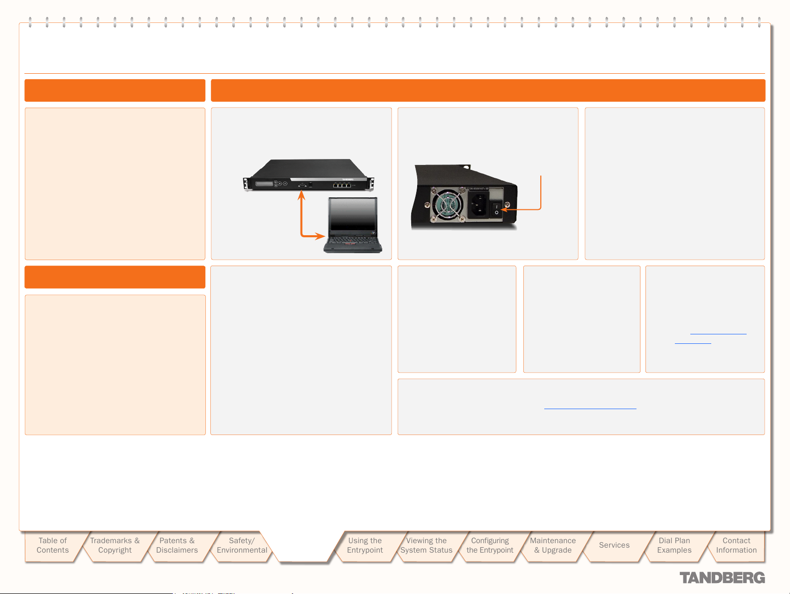
RS 232 cable. To control
the Entr ypoint using the
data port, connect an
RS 232 cable between
the Entr ypoint’s RS 232
connector and the
COM-por t on a PC. See
Entrypoint Configuration
and the Data Port
Command Interface User
Guide (available separately)
for more on this.
Table of
Contents
D 14050.04
10.2007
Trademarks &
Copyright
Patents &
Disclaimers
Safety/
Environmental
To Get You
To Get You
Up and Going
up and Going
LAN cable. To use
the Entr ypoint on
IP, connect a LAN
cable from the LAN
1 connector on the
Entrypoint to your
network. The LAN 2, 3
and 4 connectors are
not used and should be
left open.
Using the
Entrypoint
Viewing the
System Status
11
ISDN PRI or BRI cables. The E1/T1 cable should be
connected to a CSU (Channel Ser vice Unit). You will
need a CSU between your Entr ypoint and the PRI line
from your network provider.
Configuring
the Entr ypoint
Maintenance
& Upgrade
Services
Power cable. Connect
the system power
cable to an electrical
distribution socket.
Dial Plan
Examples
Contact
Information
Entrypoint Features at a Glance
TANDBERG ENTRYPOINT
USER GUIDE
About the Entrypoint
The TANDBERG Entrypoint enables sites on IP and UMTS
Handsets to participate in meetings with each other with the
quality and reliability found in all TANDBERG equipment. An
Entrypoint system opens up a wide range of interactive video
and call routing ser vices.
Entrypoint Capacity – Typical Scenarios
Due to the fixed bandwidth of UMTS video telephony every
call will be limited to 64 Kbits/s. This offers a capacity of 30
simultaneous calls through an E1 PRI, 23 simultaneous calls
through a T1 PRI, or 8 calls through a 4 × BRI. Due to audio
transcoding (AMR to G.711) the bandwidth at IP side is 109
Kbits/s per session, 64 Kbits/s G.711 audio and 45 Kbits/s
H.263 video calling 3G to H.323 or SIP endpoints. For calls
between H.323 endpoints it is possible to set up 60 sessions
between 768 and 192 kbit.
Features Highlights
IP Services and Procedures
H.324m, SIP and H.323 support•
Service Prefix•
Load balance.•
UMTS Services
The TANDBERG Entrypoint of fers a variety of UMTS dial-in
services:
Direct Inward Dialling (DID) – the destination endpoint is
•
determined from the dialled number
Interactive Video Response (IVR) – the destination endpoint
•
can be selected via touch tones.
TMS Corporate Director y – the destination end point can be
•
selected via a search in a TMS phonebook.
Menu – the destination end point or service can be selected
•
via a menu.
Security
Secure Access - support XML/SOAP over HTTPS, Web (HTTP) •
encrypted password and the services that can be disabled.
Video Quality
H.263 video compression.•
Audio Quality
AMR, G.711 audio compression•
Suppor t AMR bit rate 4.75 Kbit – 12.2 Kbit.•
Interoperability
Worldwide compatibility with standards-based •
videoconferencing systems
Compatible with all available WCDMA H.324M video telephony
•
capable handsets supporting DTMF tones.
Management Interfaces
SOAP (Simple Object Access Protocol) is a lightweight protocol
for exchange of information in a decentralized, distributed
environment.
XML (Extensible Markup Language) is a flexible way to create
common information formats and share both the format and
the data on the World Wide Web, intranets, and elsewhere.
This functionality can be used by management systems like the
TANDBERG Management Suite to control the Entrypoint
HTTP Web-inter face for system management, call management
such as diagnostics and software uploads
HTTPS Hypertex t Transfer Protocol over Secure Socket Layer is
a Web protocol that encrypts and decrypts user page requests
as well as the pages that are returned by the Web ser ver. It uses
Secure Socket Layer (SSL) as a sublayer under its regular HT TP
application layering. HTTPS uses port 443 instead of HTTP port
80 in its interactions with the lower layer, TCP/IP. SSL uses a
40-bit key size for the RC4 stream encryption algorithm, which
is considered an adequate degree of encr yption for commercial
exchange.
Network and Features
Call rate of 64 kbit on ISDN side and 768 kbps on IP side for •
each call is supported through the Entrypoint.
Interactive Video and voice Response (IVR).
•
Default Entrypoint ser vice when calling Border Controller IP •
number
Suppor t voice only calls (VoIP gatewaying)
•
Video IVR
Selecting IP endpoint from address book.•
Table of
Contents
D 14050.04
10.2007
Trademarks &
Copyright
Patents &
Disclaimers
Safety/
Environmental
To Get You
To Get You
Up and Going
up and Going
Using the
Entrypoint
Viewing the
System Status
12
Configuring
the Entr ypoint
Maintenance
& Upgrade
Services
Dial Plan
Examples
Contact
Information
The Front and Rear Panels
TANDBERG ENTRYPOINT
USER GUIDE
About the Rear Panel LED Operation
G r e e n : Normal operation.
•
Red Alarm or Loss of Signal (LoS) indicates that there is no
•
signal and thus no framing information received. A defective
or unplug ged PRI cable will produce the same effect.
Yellow Alarm or Remote Alarm Indicator (RAI) means that
•
the Entrypoint is receiving framing info, but in this framing
info the other side tells the Entr ypoint that it is not reading
the Gateway’s transmitted framing information. Typically, this
may be a broken connector in the transmit (TX) part of the
PRI cable. This could also indicate weak or noisy signal in the
transmit (TX) part of the PRI cable.
Blue Alarm indicates that the received frames are not
•
synchronized properly.
No LED’s illuminate, indicates that layer one framing is
•
working (right protocol like for example EURO ISDN selected),
however, there is a problem at layer 2 caused by for example
a CRC4 configuration mismatch.
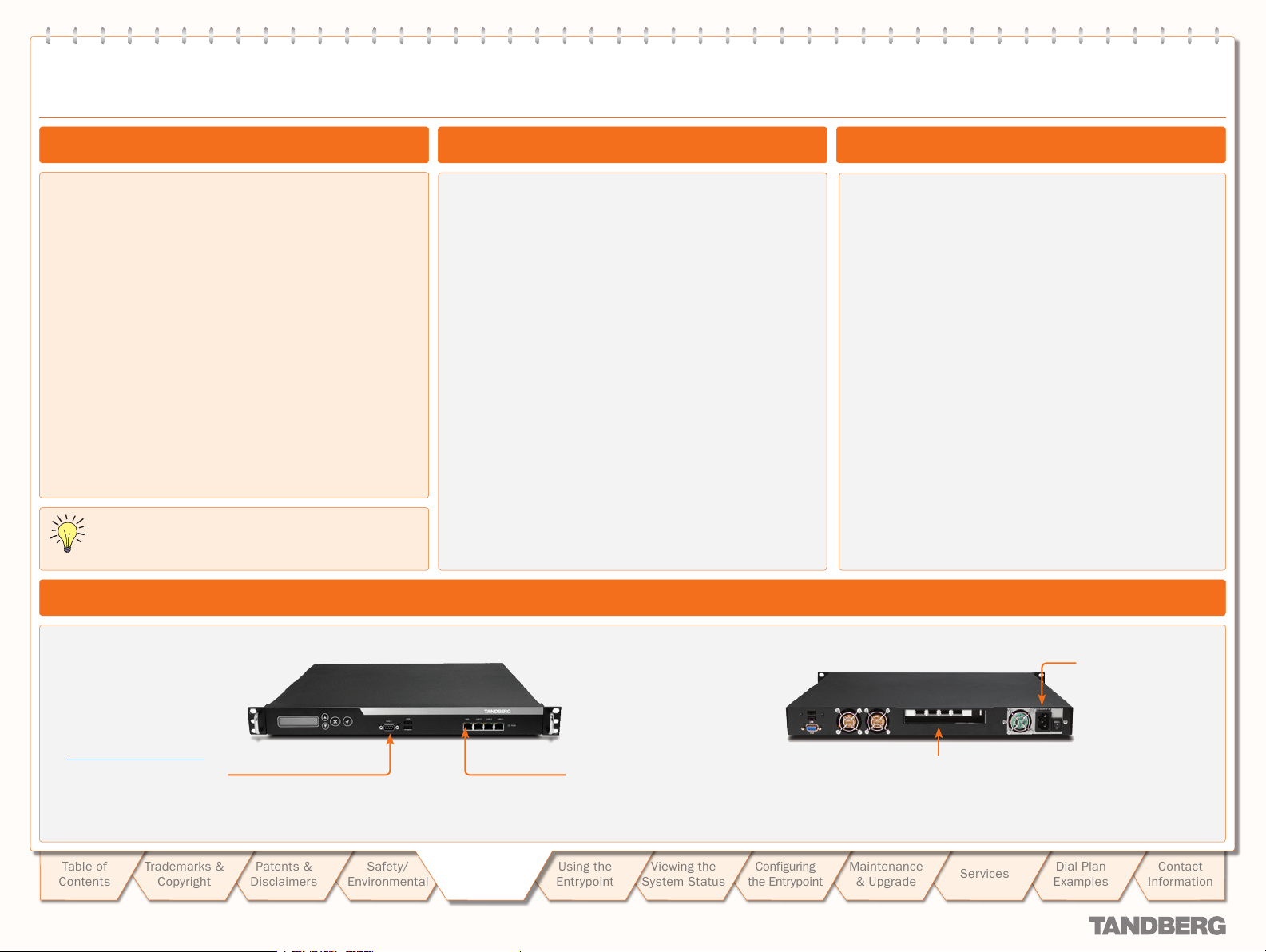
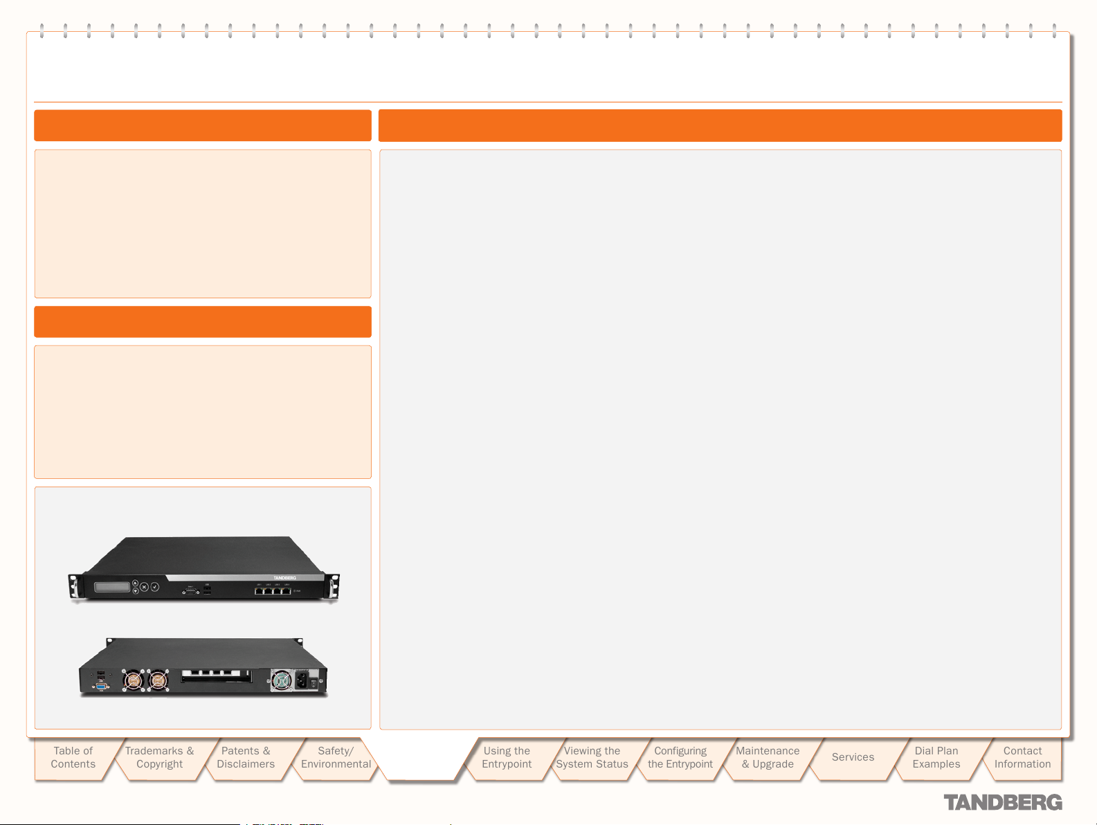
Entrypoint Start-up
To start the Entrypoint, simply connect the power cable, and
press the power switch button at the back side to position 1.
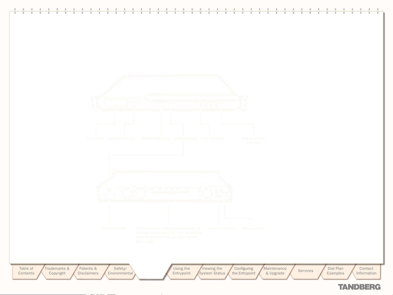
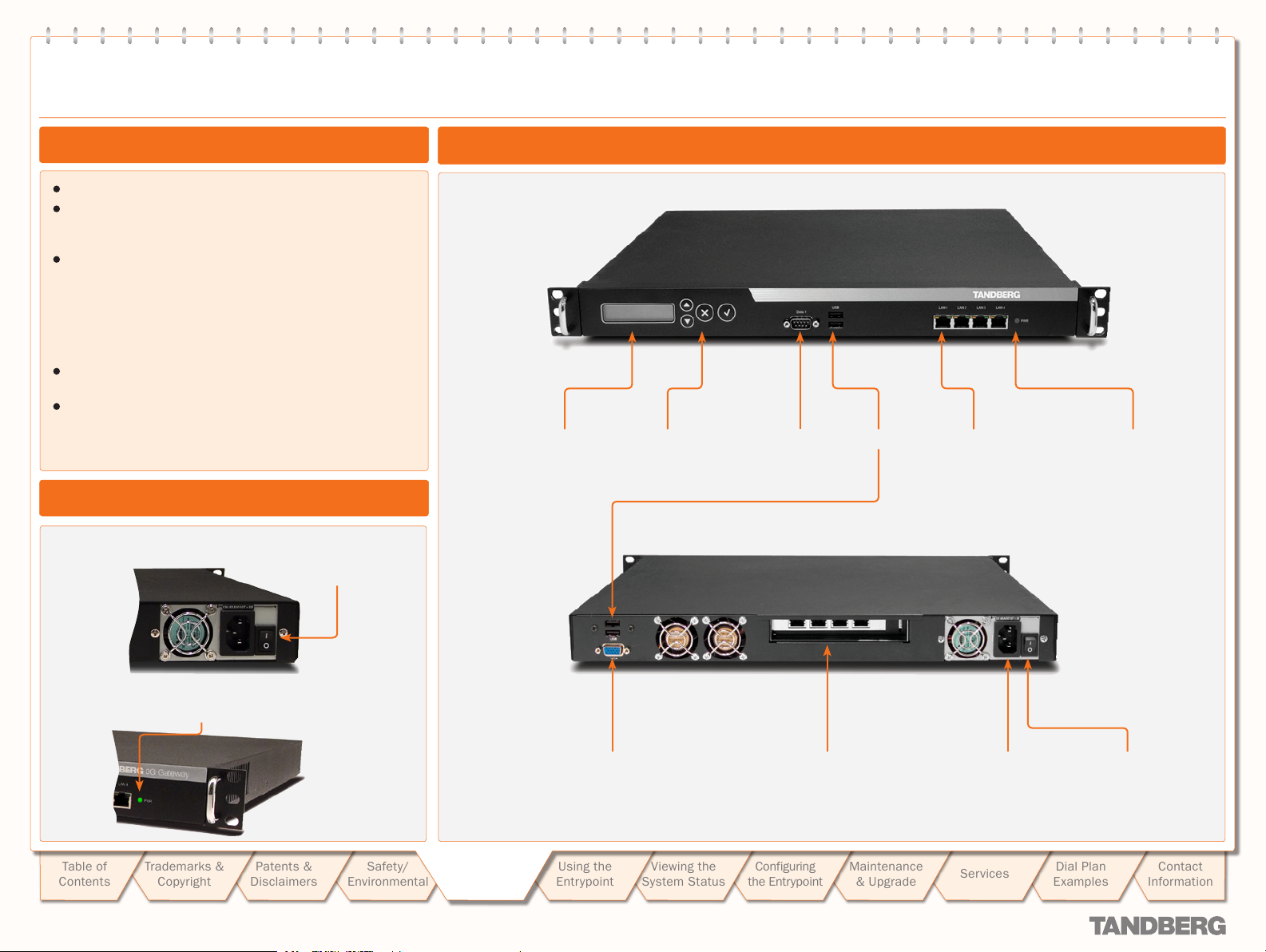
Power switch
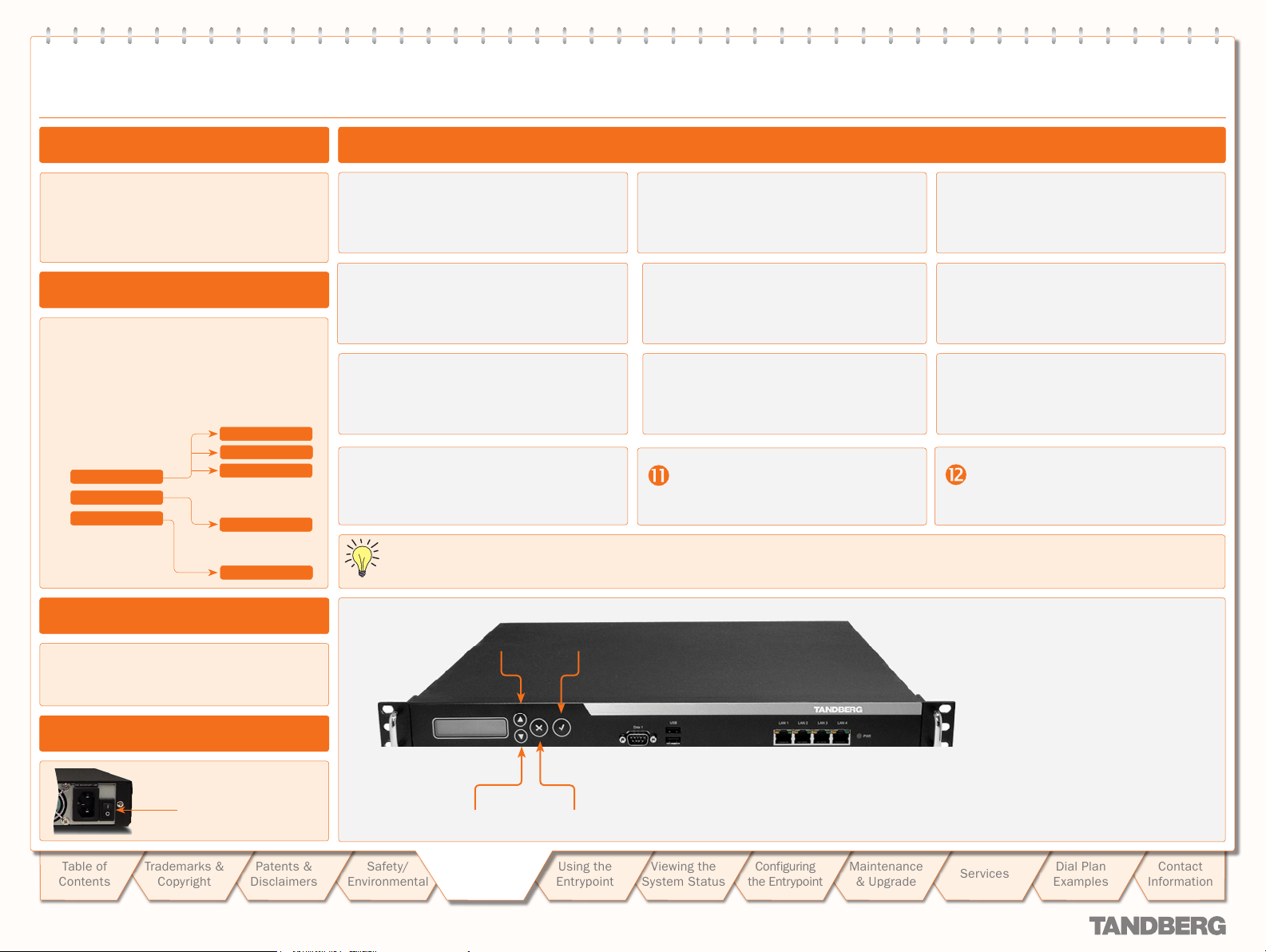
Connectors, Switches, Display, and Buttons
LCD panel Control buttons RS 232 interface LAN interfaceUSB inter face Power On/Off
indicator
On the front panel of the system the power indicator LED,
marked Pwr, will turn GREEN.
Table of
Contents
D 14050.04
10.2007
Trademarks &
Copyright
Patents &
Disclaimers
Environmental
Safety/
To Get You
To Get You
Up and Going
up and Going
VGA connector Power connector Power switch
Using the
Entrypoint
Viewing the
System Status
1 PRI inter face or 4 BRI inter faces
depending on the configuration ordered,.
Configuring
the Entr ypoint
Maintenance
& Upgrade
Services
Dial Plan
Examples
13
Contact
Information
Conguring Your Entrypoint via the RS 232
TANDBERG ENTRYPOINT
USER GUIDE
About Gateway Configuration
The Entr ypoint requires some basic
configurations before it can be used. It will be
necessary to find the IP -address and to create
the dial-in and dial-out services to program
the ISDN-PRI Line numbers.
Configuration via the Front Panel
As an alternative to the configuration via
RS 232 you may use the LCD panel to
configure and check the IP settings, as well as
to reboot the system. This is outlined on the
next page.
Make sure the Entrypoint is Off and
connect an RS232 cable between the
Entrypoint and a PC.
To assign a static IP-address, t ype
Xconf ip Assigment: “Static”
and
Xconf ip address <IPAddr>
To assign an IP Subnetmask, type
Xconf ip address subnetmask
<subnet ma sk>
Configuring via the RS 232
Switch on the Entrypoint.
Restar t the Entrypoint.
Power switch
Star t a WEB browser
and enter the
IP-address of the
Entrypoint. Default
password: TANDBERG
Note the case sensitivity!
Star t a terminal program on the PC and
configure it to:
115200, 8, 1, None
To configure the
Entrypoint for UMTS
dial-in, enter PRI or BRI
numbers and dial in
number(s). For details,
see Configuring the
Entrypoint.
Table of
Contents
D 14050.04
10.2007
Trademarks &
Copyright
Patents &
Disclaimers
To assign an IP Gateway address, type
Xconf ip address gateway
<gateway IP-address>
Safety/
Environmental
To Get You
To Get You
Up and Going
up and Going
Using the
Entrypoint
Viewing the
System Status
14
To configure the Entrypoint for IP dial in, register the Entrypoint to a Gatekeeper and enter
H.323 ser vices. For details, see Configuring the Entrypoint
Configuring
the Entr ypoint
Maintenance
& Upgrade
Services
Dial Plan
Examples
Contact
Information
Conguring the IP Address via the Front Panel
TANDBERG ENTRYPOINT
USER GUIDE
About Entrypoint Configuration
The Entr ypoint requires some basic
configurations before it can be used. It is
necessary to configure the IP-address and
to create the dial-in and dial-out services to
program the ISDN-PRI Line numbers.
Configuring via the Front Panel
The LCD panel makes it possible to configure
and check the IP set tings as well as to reboot
the system. The front panel LCD menu items
are as follows:
Menu Hierarchy
Main Menu
IP Settings
IP Information
Commands
IP Settings
IP Address
IP Netmask
IP Default GW
IP Information
IP Address
Commands
Reboot
Configuring the IP Address via the Front Panel
Switch on and press any key to produce
the Main Menu. Use UP/DOWN to navigate
to the IP Settings, if needed.
In addition to configure the IP address you
must also configure the default-gateway,
netmask and set IP assignment to static.
Use ENTER to enter Digit Altering Mode.
When finished editing use ESC to go to
the Conf irm change menu.
DHCP assigned IP-addresses are supported by the TANDBERG Entr ypoint (factor y default).
Press ENTER to access the IP Settings
submenu.
Press ENTER again to produce the
curs or.
Use UP/DOWN to alter the digit value.
Use the UP/DOWN key to select yes or
no and ENTER to confirm.
Use the UP/DOWN keys to select IP
Address.
Use UP/DOWN keys to navigate
between the digits of the number.
Press ENTER as many times as needed
to move to the next digit to be altered
and alter this digit.
Use ESC key to navigate back to the
main menu.
Configuration via RS 232
As an alternative to the configuration via the LCD
panel you may use RS 232 to configure and the
system. This is treated on the previous page.
Switching On the Unit
Power switch
Table of
Contents
D 14050.04
10.2007
Trademarks &
Copyright
Patents &
Disclaimers
Safety/
Environmental
UP key
DOWN key ESC key
To Get You
To Get You
Up and Going
up and Going
ENTER key
Using the
Entrypoint
Viewing the
System Status
15
Configuring
the Entr ypoint
Maintenance
& Upgrade
Services
Dial Plan
Examples
Contact
Information
Using the Entrypoint
This section of the Entrypoint User Guide shows you how
to gain access to the system, how to get an overview of
ongoing calls, the menu operating principles, and how to
dial from UMTS as well as from IP. Examples are provided
for your convenience.
TANDBERG ENTRYPOINT
TANDBERG ENTRYPOINT
USER GUIDE
USER GUIDE
Table of
Contents
D 14050.04
10.2007
Trademarks &
Copyright
Patents &
Disclaimers
Safety/
Environmental
To Get You
Up and Going
Using the
Using the
Entrypoint
Entrypoint
Viewing the
System Status
16
Configuring
the Entr ypoint
Maintenance
& Upgrade
Services
Dial Plan
Examples
Contact
Information

Starting Up the Entrypoint
TANDBERG ENTRYPOINT
TANDBERG ENTRYPOINT
USER GUIDE
USER GUIDE
Entrypoint Start-up
To start the Entrypoint, simply connect the
power cable, and set the power switch button
(both at the rear) to position I.
Power switch
On the front panel of the system the power
indicator LED, marked PWR, will turn GREEN.
You may access the
Entrypoint by entering the
IP-address of the Entr ypoint
in a standard WEB-browser.
You will then be asked to
enter a password. You will
need to enter admin as
user name. The default
password for the Entrypoint
is TANDBERG. Remember
that the password is case
sensitive. Note that you may
also use SSH and Telnet to
configure the Entrypoint.
Accessing the Entrypoint
USER NAME is admin
PASSWORD. Default
password is TANDBERG (NB!
case sensitive)
Forgot the Password?
Table of
Contents
D 14050.04
10.2007
Trademarks &
Copyright
Patents &
Disclaimers
Reboot the Entrypoint.
Connect to the Entrypoint via the serial inter face once it has
restarted.
Login with User Name pwrec.
No password is required.
Safety/
Environmental
To Get You
Up and Going
Using the
Using the
Entrypoint
Entrypoint
System Status
17
Viewing the
Configuring
the Entr ypoint
You will be prompted for a new password.
The pwrec account is active for one minute following a restar t.
Beyond that time, the system will have to be restarted to
change the password.
Maintenance
& Upgrade
Services
Dial Plan
Examples
Contact
Information

An Overview of the Management Menu System
The Overview Window
TANDBERG ENTRYPOINT
TANDBERG ENTRYPOINT
USER GUIDE
USER GUIDE
The System Status windows
of the Entrypoint can be
accessed via the default
URL: http://Entrypoint_IP_
Address/overview.
Remote Number. This is the
inbound number.
Net. Indicates the net type,
i.e. H.323, H.324m, SIP or
Streaming.
Service. Indicates the
service type, i.e. DID, IVR,
TMS phonebook, Menu.
Duration. Duration of the
call in hours, minutes and
seconds.
Log out and Help. Click on
the little key icon to log
out and on the question
mark to gain access to Help
features.
Actions. Clicking on view
details reveals both
incoming and outgoing call
leg information.
The Overview window
presents information about
all calls routed through the
Entrypoint.
How to access the
Management Menu
System is described
on the previous page.
Table of
Contents
D 14050.04
10.2007
Trademarks &
Copyright
Patents &
Disclaimers
Safety/
Environmental
To Get You
Up and Going
Using the
Using the
Entrypoint
Entrypoint
Viewing the
System Status
18
Configuring
the Entr ypoint
Maintenance
& Upgrade
Services
Clicking on a service
call entr y shows the
service call details
of the respective call, like
e.g. inbound and outbound
numbers – see the nex t page
for more on this.
Dial Plan
Examples
Contact
Information

Service Call Details
TANDBERG ENTRYPOINT
TANDBERG ENTRYPOINT
USER GUIDE
USER GUIDE
About Service Call Details
The View Call Details tab
presents information about
all calls routed through the
Entrypoint, i.e. inbound and
outbound numbers, duration
of the calls and call status
– i.e. ringing (alerting),
connecting and connected.
Incoming. Indicates the
information belonging to the
call leg of the calling party.
Outgoing. Indicates the
information belonging to the
call leg of the called party/
service.
Status. Either alerting,
connected or disconnected.
The Service Call Details Window
Incoming number. The service number,
i.e. the number an external user dialed
to get access to a portal ser vice.
Service. Indicates the service name, i.e.
DID, IVR, TMS Phonebook, Menu.
Duration. Indicates the duration of the
call in hours, minutes and seconds.
Details. Remote numbers of the
Incoming calls are the numbers
of the calling party and remote
numbers of the Out going calls are
the numbers of the called par ty
or service. Clicking View details
reveals the Call Details, i.e. details
belonging to the respective call leg.
When View Details Has Been Selected
Remote Number. For inbound call
legs it represents the number of the
calling party, for outbound call legs it
represents the number of the called
party or ser vice
Net. Indicates the net t ype,
i.e. H.323, H.324m, SIP or
Streaming.
Incoming Number. Ser vice
number; can only be
represented for inbound call
legs.
Table of
Contents
D 14050.04
10.2007
Trademarks &
Copyright
Patents &
Disclaimers
Safety/
Environmental
To Get You
Up and Going
Using the
Using the
Entrypoint
Entrypoint
Viewing the
System Status
19
Configuring
the Entr ypoint
Maintenance
& Upgrade
Duration. Duration of this call leg in
hours, minutes and seconds.
Services
Dial Plan
Examples
Contact
Information

Call Setup via Default Services
TANDBERG ENTRYPOINT
TANDBERG ENTRYPOINT
USER GUIDE
USER GUIDE
About Default Services
The Entr ypoint is equipped with a number
of persistent default services, i.e. ser vices
stored in the on- board non-volatile memory.
Therefore, these services will always
be available after a system restart. The
following persistent default services can be
distinguished:
Direct Inwards Dialling (DID)
• – Defines a
one- on-one relation bet ween an inbound
and an outbound number.
Dial Ex tension (IVR)
• – Also known as
Interactive Voice/Video Response (IVR),
defines a relation between an inbound
number and an interactive ser vice, i.e. a
menu, via which an outbound ser vice can
be connected to. The outbound service
can be an audio or video service or an
externally connected endpoint.
Menu ser vice
• – A menu based call
directo ry.
TMS Corporate Director y
• (phone book) – A
connection with the installed TANDBERG
Management System (TMS) phone book
is set up. Via the phone book menu an
outbound call to another endpoint, e.g. a
3G Mobile, H.323 or SIP endpoint, can be
set up.
DID – Direct Inward Dialling
Example Hotline
Entry details:
Enabled: Check
Name: H.324m-H.323
Net Type: H.324m
Prefix: 67890000
Suffix:
Service Type: Direct Inwards Dialling
Arguments:
Net Type: H.323
AV Mode: Auto + fallback to audio
Prefix: 51234
Suffix
Use Remainder: No
Allow For warding: No
When dialling number 67890000 this will match without leaving a
remainder. The H.323 number that will be connected to will be: 51234
(construction: prefix). When dialling number 67894321 there will be no
match. When dialling number 678900009876 one is also connected to
the same H.323 endpoint, since there is a match on 67890000 and the
remainder, i.e. 9876, is discarded. Note that Use Remainder is set to No!
Dial Extension (IVR) Example
Example
A 3G handset user calls a Dial Extension ser vice number.1.
The Entr ypoint activates the 2. Welcome screen and sound.
The Entr ypoint, when set in the dial plan, shows the DTMF Information screen.3.
The 3G handset user enters the extension (H.324m, H.323 or SIP alias) followed by the 4. # (pound-sign) to indicate end of number.
The Entr ypoint starts to call the endpoint and the 5. Connecting picture and sound are activated.
When the call is connected audio and video are transmitted through the Entrypoint. 6.
Table of
Contents
D 14050.04
10.2007
Trademarks &
Copyright
Patents &
Disclaimers
Safety/
Environmental
To Get You
Up and Going
Using the
Using the
Entrypoint
Entrypoint
Viewing the
System Status
20
Configuring
the Entr ypoint
Maintenance
& Upgrade
Services
Dial Plan
Examples
Contact
Information

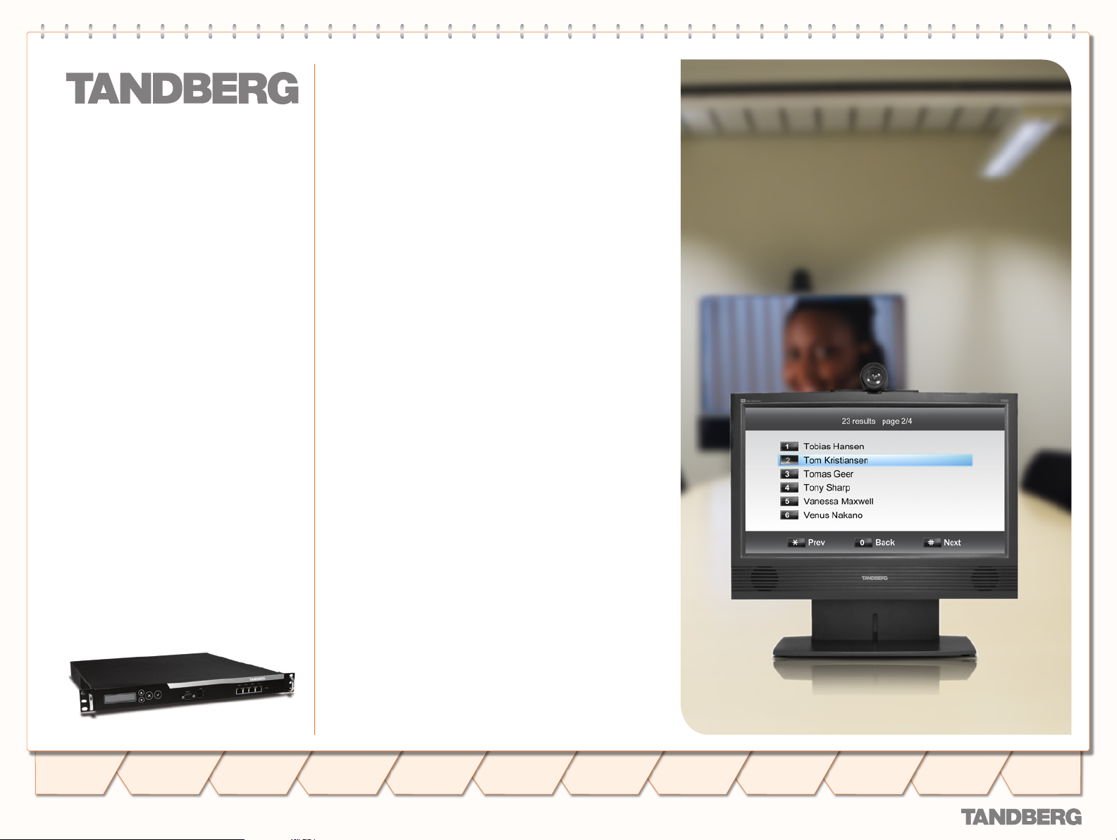
Dialling from UMTS – Using Phone Book
TANDBERG ENTRYPOINT
TANDBERG ENTRYPOINT
USER GUIDE
USER GUIDE
About TMS Corporate Directory
The TMS Corporate Directory ser vice allows
one Endpoint, i.e. a UMTS phone, H.323 or
SIP, to dial another Endpoint directly, without
knowing or having to (manually) enter the
extension number via DTMF. TMS Corporate
Directory is a menu based dial -in method,
which combines a directory listing from TMS
with IVR. In this mode the user can search
in the global address book provided via TMS
using the alphanumeric part of the keypad.
The TMS Corporate Directory ser vice searches
and displays entries matching the user input
string.
Example of IVR – Using the Phone Book
Example 1
Pressing 1. 8 once, twice and three times in a row followed by a # sign, will result in a list with names star ting with a letter t, u or v respectively.
Pressing 2. 8 once, thereafter pressing 6 three times results in the search string to. Pressing 8 twice and 6 once, results in um. Pressing 8 three time
and 6 three times results in vo. If one wants to reach Tom Arne press 8 followed by three times 6, i.e. search string to.
To select the person you wish to dial, press the corresponding key to place a call to that person.3.
The star (
) key on the keypad is used as backspace.
*
Table of
Contents
D 14050.04
10.2007
Trademarks &
Copyright
Patents &
Disclaimers
Safety/
Environmental
To Get You
Up and Going
Using the
Using the
Entrypoint
Entrypoint
Viewing the
System Status
21
Configuring
the Entr ypoint
Maintenance
& Upgrade
Services
Dial Plan
Examples
Contact
Information

Viewing the System Status
To view the current status of the system, hover with the
mouse pointer over Status to produce a drop-down menu
as shown here. This section discusses the respective
menu items.
TANDBERG ENTRYPOINT
TANDBERG ENTRYPOINT
USER GUIDE
USER GUIDE
Table of
Contents
D 14050.04
10.2007
Trademarks &
Copyright
Patents &
Disclaimers
Safety/
Environmental
To Get You
Up and Going
Using the
Entrypoint
Viewing the
Viewing the
System Status
System Status
22
Configuring
the Entr ypoint
Maintenance
& Upgrade
Services
Dial Plan
Examples
Contact
Information

ISDN/PRI Status (PRI Versions only)
TANDBERG ENTRYPOINT
TANDBERG ENTRYPOINT
Select PRI Status to access the PRI Status pane.
The PRI status indication consist of 3 fields (see About the Rear
Panel LED Operation below for PRI status):
Active – Indicates weather the PRI por t is active or not.
•
Total number of channels – indicates the maximum available •
number of simultaneous ISDN slots (calls) per por t; typically
30 for an E1 PRI and 8 for an E1 BRI.
Number of free channels – indicates the number of free B-
•
channels on ISDN.
To view the ISDN PRI status, select the
• ISDN status item of
the Status tab.
USER GUIDE
USER GUIDE
About the Rear Panel LED Operation
In addition to the web page indications, the ISDN inter face also
contains 4 LEDs, located at the the Entrypoint rear panel.
These LEDs indicate the following PRI status:
G r e e n : Normal operation
•
Red Alarm or Loss of signal (LOS) indicates that there is
•
no signal and thus no framing info received. A defect or
unplug ging the PRI cable will produce the same effect.
Yellow Alarm or Remote Alarm Indicator (RAI) means that the
•
Entrypoint is receiving framing info, but in this framing info
the other side tells the Entrypoint that it is not reading the
Gateway’s transmitted framing info. Typically, this may be a
broken connector in the transmit (TX) part of the PRI cable.
This could also indicate weak or noisy signal in the transmit
(TX) part of the PRI cable.
Blue Alarm indicates that the received frames are not
•
synchronized properly.
No LED’s illuminate, indicates that layer one framing is
•
working (right protocol like for example EURO ISDN selected),
however there is a problem at layer 2 caused by for example
a CRC4 configuration mismatch.
Table of
Contents
D 14050.04
10.2007
Trademarks &
Copyright
Patents &
Disclaimers
Safety/
Environmental
To Get You
Up and Going
Using the
Entrypoint
Viewing the
Viewing the
System Status
System Status
23
Configuring
the Entr ypoint
Maintenance
& Upgrade
Services
Dial Plan
Examples
Contact
Information

ISDN/BRI Status (BRI Versions only)
TANDBERG ENTRYPOINT
TANDBERG ENTRYPOINT
Select ISDN/BRI Status to access the ISDN/BRI Status pane.
BRI hardware status indication
The screenshot shows the status page of a BRI version of the
Entrypoint. The BRI status displays the conditions of ISDN
layer 1 and 2 separately. Green indicates up and in sync. Red
indicates not in sync and indicate probably a disconnected
ISDN line.
Besides the indications on the webpage each ISDN BRI
interface located at the back-side of the Entrypoint has a green
and orange LED. The meanings of these LEDs are:
Green: Layer 1 of the ISDN signalling is up.
•
Green and Orange. This indicates that both layers 1 and 2
••
are up. In some countries the orange LED can blink on a
regular interval, or is turned on when there is an active call.
No LED’s illuminate. This indicates that there is no
•
connection or a wrongly wired connection.
USER GUIDE
USER GUIDE
Table of
Contents
D 14050.04
10.2007
Trademarks &
Copyright
Patents &
Disclaimers
Safety/
Environmental
To Get You
Up and Going
Using the
Entrypoint
Viewing the
Viewing the
System Status
System Status
24
Configuring
the Entr ypoint
In some countries layer 2 can be down when there is no
activity (ongoing connections).
However, layer 2 should become active once a call is
made or received.
In case the BRI Entrypoint is connected with less than 4
BRI lines, the BRI interfaces with the highest number(s)
should be left open. For example when only 2 ISDN lines
are used they should be connected with interface 1 and 2.
Maintenance
& Upgrade
Services
Dial Plan
Examples
Contact
Information

H.323 Gatekeeper Status
TANDBERG ENTRYPOINT
TANDBERG ENTRYPOINT
USER GUIDE
USER GUIDE
About H.323 Status
H.323 Gatekeeper Status
shows the current status of
the Gatekeeper registration.
To view H.323 gatekeeper
status, as indicated in the
screenshot shown here,
select H.323 Status item of
the Status tab.
Registration Status Registered
Registration Status. If Registered, the
Entrypoint is registered to the Gatekeeper with
below mentioned Address and Port.
IP Address. Shows the IP address of the
Gatekeeper.
Port. Shows the destination port number on
the Gatekeeper.
Registration Status Inactive
In case the Entrypoint is in direct mode or
in case the gatekeeper IP address is filled
in incorrectly, the Entrypoint will not be
registered with the Gatekeeper, and the
Registration status is stated as Inactive.
Note that, since this
target system is not
an endpoint it is not
possible to use its IP
address to place calls to or
through the Entr ypoint!
Table of
Contents
D 14050.04
10.2007
Trademarks &
Copyright
Patents &
Disclaimers
Safety/
Environmental
To Get You
Up and Going
Using the
Entrypoint
Registration Status Rejected
Viewing the
Viewing the
System Status
System Status
Configuring
the Entr ypoint
25
Maintenance
& Upgrade
Registration status will show Rejected when:
Gatekeeper unreachable; the Entrypoint’s
•
H.323 stack returns this reject message in
case the gatekeeper is down.
Duplicate alias; a system with an identical
•
name has already been registered.
Authentication failure; Authentication
•
ID and/or Authentication Password are
incorrect.
Services
Dial Plan
Examples
Contact
Information

Services
TANDBERG ENTRYPOINT
TANDBERG ENTRYPOINT
The default services, which
come standard with an
Entrypoint system, are:
Direct Inwards Dialling
•
IVR•
TMS Corporate Director y•
Entrypoint Service•
USER GUIDE
USER GUIDE
Table of
Contents
D 14050.04
10.2007
Trademarks &
Copyright
Patents &
Disclaimers
Safety/
Environmental
To Get You
Up and Going
Using the
Entrypoint
Viewing the
Viewing the
System Status
System Status
26
Configuring
the Entr ypoint
Maintenance
& Upgrade
Services
Dial Plan
Examples
Contact
Information

System Information
TANDBERG ENTRYPOINT
TANDBERG ENTRYPOINT
Select System Information
to access the System
Information pane.
This pane provides an
overview of installed
software and hardware.
USER GUIDE
USER GUIDE
Table of
Contents
D 14050.04
10.2007
Trademarks &
Copyright
Patents &
Disclaimers
Safety/
Environmental
To Get You
Up and Going
Using the
Entrypoint
Viewing the
Viewing the
System Status
System Status
27
Configuring
the Entr ypoint
Maintenance
& Upgrade
Services
Dial Plan
Examples
Contact
Information

System Resources
TANDBERG ENTRYPOINT
TANDBERG ENTRYPOINT
To view available resources
of the Entrypoint, open
System Resources of the
Status tab, as shown here.
This menu item shows the
amount of active sessions,
i.e. video and audio calls on
this system. The system load
percentage indicates the
processor load.
These figures depend on the
system’s use of resources.
The use of Call Forwarding
in dial plans reduces system
load and therefore increases
the number of simultaneous
calls.
USER GUIDE
USER GUIDE
Table of
Contents
D 14050.04
10.2007
Trademarks &
Copyright
Patents &
Disclaimers
Safety/
Environmental
To Get You
Up and Going
Using the
Entrypoint
Viewing the
Viewing the
System Status
System Status
28
Configuring
the Entr ypoint
Maintenance
& Upgrade
Services
A System Load of 0 %
indicates no load on
the Entr ypoint!
Dial Plan
Examples
Contact
Information

Configuring the Entrypoint
To configure the Entrypoint, hover with the mouse pointer
over the System configuration to produce a drop-down
menu. The drop -down menu consists of 6 items, i.e. ISDN,
IP, H.323, SIP, SNMP and System, to configure respective
system parts.
Changing settings in the menus belonging to the ISDN, IP
and System items only become effective after a system
reboot, therefore these items all contain Restart buttons.
Every configuration item is supported with a ? button for
information about this specific item.
TANDBERG ENTRYPOINT
TANDBERG ENTRYPOINT
USER GUIDE
USER GUIDE
Table of
Contents
D 14050.04
10.2007
Trademarks &
Copyright
Patents &
Disclaimers
Safety/
Environmental
To Get You
Up and Going
Using the
Entrypoint
Viewing the
System Status
29
Configuring
Configuring
the Entr ypoint
the Entr ypoint
Maintenance
& Upgrade
Services
Dial Plan
Examples
Contact
Information

ISDN/PRI Conguration (ISDN/PRI Versions only)
TANDBERG ENTRYPOINT
TANDBERG ENTRYPOINT
USER GUIDE
USER GUIDE
PRI Inter face Configuration.
Indicates the lowest
numbered E1/T1 B-channel
the system is allowed to
use for each PRI-line when
selecting channels for
outgoing calls. Not in use in
this version.
Enable CRC-4. Used for most
E1-PRI configurations. If your
network equipment does not
suppor t this feature, switch
off PRI CRC-4.
Fractional line operation:
Low Channel. Indicates
the lowest numbered E1/
T1 B-channel the system is
allowed to use for each PRIline when selecting channels
for outgoing calls. Presently,
this setting has no ef fect.
Save. When all settings are
entered, click on Save to
store the new settings.
Note that changing from E1
to T1 configuration requires
a restar t of the unit (click
Restart to restart the unit).
PRI Protocol. Select between the following PRI
protocols:
NI (National ISDN)
•
ATT (AT&T Custom)•
Euro (ETSI = Euro ISDN)•
Japan (Japan/Taiwan ISDN)•
Outgoing Bearer capability
Within ISDN different bearer capabilities are
used to signal the type of data (Voice, Data,
H320, H.324M), which is used by telephony
switches and other equipment to determine
how to handle data or calls (compressing voice
data neglect etc). The outgoing bearer capability
sets the ISDN bearer capability for the outgoing
telephone (voice only) and video telephone calls.
H.324M:
• This ITU standardized capability is
selected for outgoing calls by default.
UDI:
• In some situations the switch does
not accept calls which use the correct
H.324M capability. This set ting makes it
possible to use the Entrypoint in these
situations via selecting UDI.
Prefix on National/International Numbers•
Specifies the prefix, which has to be added •
to National and International numbers,
respectively.
The signalling specifies whether the
•
call is national or international. Since
these prefixes are removed from inbound
telephone numbers, the correct prefixes
have to be added on call -backs.
These settings only apply if the Service
providers network uses prefixes for national
and international calls.
All incoming calls are accepted
independent of their bearer
capabilities, consequently audio calls
are accepted as well.
Table of
Contents
D 14050.04
10.2007
Trademarks &
Copyright
Patents &
Disclaimers
Safety/
Environmental
To Get You
Up and Going
Using the
Entrypoint
Viewing the
System Status
30
Configuring
Configuring
the Entr ypoint
the Entr ypoint
Maintenance
& Upgrade
Services
Dial Plan
Examples
Contact
Information

ISDN/BRI Conguration (ISDN/BRI Versions only)
TANDBERG ENTRYPOINT
TANDBERG ENTRYPOINT
USER GUIDE
USER GUIDE
Select BRI to access the BRI
Configuration pane.
Save. When all settings
are entered, click on Save
to make the new settings
become effective.
You cannot configure
ISDN BRI lines for
special functions like
dial out only! The Gateway
will automatically select a
free BRI line for H.323 to
3G calls and possibly block
a DiD or an IVR menu when
the BRI lines have different
numbers. Consequently, we
strongly recommend that
all ISDN BRI lines have the
same number range!
Contact your ISDN or
telecom supplier about
numbering plans of ISDN
lines.
BRI Protocol. Select between the following BRI
protocols:
ETSI (Euro ISDN)
•
National ISDN•
AT&T Custom•
Japan/Taiwan ISDN•
Outgoing Bearer capability. Within ISDN
different bearer capabilities are used to signal
the type of data ( Voice, Data, H320, H.324M),
which is used by telephony switches and other
equipment to determine how to handle data
or calls (compressing voice data neglect etc).
The out going bearer capability sets the ISDN
bearer capability for the outgoing telephone
(voice only) and video telephone calls.
H.324M: This ITU standardized capability
•
is selected for outgoing calls by default.
UDI: In some situations the switch does
•
not accept calls which use the correct
H.324M capability. This set ting makes it
possible to use the Entrypoint in these
situations via selecting UDI.
Table of
Contents
D 14050.04
10.2007
Trademarks &
Copyright
Patents &
Disclaimers
Safety/
Environmental
To Get You
Up and Going
Using the
Entrypoint
Viewing the
System Status
31
Configuring
Configuring
the Entr ypoint
the Entr ypoint
Maintenance
& Upgrade
All incoming calls are accepted
independent of their bearer
capabilities, therefore audio calls are
accepted as well.
Services
Dial Plan
Examples
Contact
Information

IP Conguration
TANDBERG ENTRYPOINT
TANDBERG ENTRYPOINT
USER GUIDE
USER GUIDE
Select IP from the
Configuration to access the IP Configuration pane.
DNS Inter face
Up to five Domain Name
Server IP addresses can be
specified here. Your LAN
administrator will provide
the correct values for these
fields. By default these fields
are set to 127.0.0.1
Date and Time Settings. An
NTP ser ver address can be
specified here to provide the
Entrypoint with up-to- date
time and date information.
Save. When ready to store
the new settings, press
Save. These settings will
take effect when the system
has been restarted.
IP Address Assignment is DHCP or Static:
DHCP:
• Dynamic Host Configuration Protocol
can be selected when a DHCP server
is present. Static IP Address, Static IP
Subnet Mask and Static IP Gateway are
ignored because these parameters are
assigned by the DHCP server.
Static:
• If Static assignment is used, the
Entrypoint’s IP address, IP subnet mask, and
the Gateway’s IP address must be specified
in the respective IP address fields.
IP Ethernet Speed provides five settings to
choose from:
Auto
• The Gateway will negotiate detect the
speed and duplex on the LAN.
10Half
• The Gateway will connect to the LAN
using 10 Mbps/Half Duplex.
10Full
• The Gateway will connect to the L AN
using 10 Mbps/Full Duplex.
100Half
• The Gateway will connect to the
LAN using 100 Mbps/Half Duplex.
100Full
• The Gateway will connect to the
LAN using 100 Mbps/Full Duplex.
IP Address.The Static IP Address defines
the network address of the Entrypoint. This
address is only used in static mode. Your LAN
administrator will provide you with the correct
address for this field.
Restar t. This button will
restar t the Entrypoint.
Any changes made in the
IP Configuration of the
Entrypoint will take effect
after the system has been
restarted.
Table of
Contents
D 14050.04
10.2007
Trademarks &
Copyright
Patents &
Disclaimers
Safety/
Environmental
To Get You
Up and Going
Using the
Entrypoint
Viewing the
System Status
32
Configuring
Configuring
the Entr ypoint
the Entr ypoint
Maintenance
& Upgrade
IP Subnet Mask.The Static IP Subnet Mask defines
the type of network. Your LAN administrator will
provide the correct value for this field.
IP Gateway.The Static Gateway IP address is
set to 127.0.0.1 by default. In case of a router
enter its address here. Your LAN administrator
will provide the correct value for this field.
Services
Dial Plan
Examples
Contact
Information

H.323 Conguration
TANDBERG ENTRYPOINT
TANDBERG ENTRYPOINT
USER GUIDE
USER GUIDE
Select H.323 to access the
H.323 Conf iguration pane.
When registered with
a gatekeeper, the
H.323 Status shows
Registered, the gatekeeper’s
IP address and the Port used
(see also Status, H.323
Status).
Dialling out from IP to
IP or ISDN, through
the Entr ypoint,
requires the use of H.323
numbers (E.164 aliases and
service prefixes). This means
that the Entrypoint must be
registered to a gatekeeper;
select the H.323 menu item
in the Configuration menu.
Save. When ready to store
the new settings, press
Save.
In case password is not
set/configured/inserted,
the Entrypoint will still
use the Authentication ID to
register with the gatekeeper.
However, when the Authentication ID is left “unused”, the
System Name field. will be used
to register the Entrypoint with
the gatekeeper instead. In case
both the Authentication ID field
and the System Name field
are “unused” the Entrypoint
can not be registered with the
gatekeeper.
Mode. Enables the Entrypoint to register with a
gatekeeper or leave it unregistered, i.e. in direct
mode. Make sure that System Name is always
set in direct mode. When registered with a
gatekeeper, the H.323 Status shows Registered,
the gatekeeper’s IP address and the Port used.
When the registration fails, the Registration status
will be rejected. Three cases can be distinguished:
Gatekeeper unreachable
• ; the Entrypoint’s H.323
stack returns this reject message in case the
gatekeeper is down.
Duplicate alias
• ; a system with an identical name
has already been registered.
Authentication failure
• ; Authentication ID and/or
Authentication Password are incorrect.
Selecting direct mode will result in no gatekeeper
registration; hence it is not possible to dial through
the Entr ypoint via alias names. The H.323 Status
shows Inactive.
IP Address.Enter the Gatekeeper IP address that
the Entr ypoint should register to. Leaving this
empty will result in direct dialling without the use
of aliases.
Authentication Mode is Off or Auto.
Of f.
• Register to the Gatekeeper without
authentication.
Auto.
• Register to the Gatekeeper with H.235
authentication using ID/Password given below.
Authentication ID and Password. Enter the ID and pass-
word required to perform H.235 authentication at the
Gatekeeper. To register with a Gatekeeper that requires
authentication, an NTP ser ver has to be configured.
If the Gatekeeper is configured with an
alternative Gatekeeper, the Status area
may report a registration to the IP address
of the alternative Gatekeeper.
Table of
Contents
D 14050.04
10.2007
Trademarks &
Copyright
Patents &
Disclaimers
Safety/
Environmental
To Get You
Up and Going
Using the
Entrypoint
Viewing the
System Status
33
Configuring
Configuring
the Entr ypoint
the Entr ypoint
Maintenance
& Upgrade
Services
Dial Plan
Examples
Contact
Information

SIP Conguration
TANDBERG ENTRYPOINT
TANDBERG ENTRYPOINT
USER GUIDE
USER GUIDE
Select SIP to access the SIP
Configuration pane.
Save. When ready to store
the new settings, press
Save. These settings will
take effect when the system
has been restarted.
SIP settings
Enabled.Entrypoint will use
this Proxy for call setup.
SIP prox y address. Enter
the IP Address of the
proxy server to which the
Entrypoint will use for call
setups.
SIP prox y port. Enter the port
number belonging to that SIP
proxy IP address.
Table of
Contents
D 14050.04
10.2007
Trademarks &
Copyright
Patents &
Disclaimers
Safety/
Environmental
To Get You
Up and Going
Using the
Entrypoint
Viewing the
System Status
34
Configuring
Configuring
the Entr ypoint
the Entr ypoint
Maintenance
& Upgrade
Services
Setting Mode to Off
will not hide the SIP
proxy address and
port settings!
Dial Plan
Examples
Contact
Information

SNMP Conguration
TANDBERG ENTRYPOINT
TANDBERG ENTRYPOINT
USER GUIDE
USER GUIDE
SNMP (Simple Network
Management Protocol) is
used for monitoring and
configuring dif ferent units in
a network. The Entrypoint’s
SNMP Agent responds
to requests from SNMP
Managers (a PC program
etc.). SNMP traps are
generated by the agent to
inform the manager about
impor tant events.
Select SNMP to access the
SNMP Configuration pane.
SNMP Mode. The SNMP operation modus can
be set to:
On
• . Turns SNMP On
Off
• . Turns SNMP O ff
ReadOnly
• . Do not send SNMP information
to the host
Tra ps Only
• . Only send SNMP information
identified as TRAPS to the host.
SNMP Community name. SNMP Community
names are used to authenticate SNMP
requests. SNMP requests must have this
‘password’ in order to receive a response from
the SNMP agent in the Entrypoint.
The SNMP Community name is case
sensitive!
System contact. Used to identify the system
contact via SNMP tools such as HPOpenView
or TANDBERG Management Suite.
Location. Used to identify system location
via SNMP tools such as HPOpenView or
TANDBERG Management Suite.
Save. Press Save to activate
new settings.
Table of
Contents
D 14050.04
10.2007
Trademarks &
Copyright
Patents &
Disclaimers
Safety/
Environmental
To Get You
Up and Going
Using the
Entrypoint
Viewing the
System Status
35
Configuring
Configuring
the Entr ypoint
the Entr ypoint
Maintenance
& Upgrade
Host IP Address (1, 2 and 3). Identifies the
IP-address of the SNMP manager. Up to three
different SNMP Trap Hosts can be defined.
Your LAN administrator should provide the
correct values for these fields.
Services
Dial Plan
Examples
Contact
Information

System
TANDBERG ENTRYPOINT
TANDBERG ENTRYPOINT
USER GUIDE
USER GUIDE
To configure the miscellaneous
settings on the Entrypoint,
select the System
Configuration item.
Save. When ready to store
the new settings, press
Save. These settings will
take effect when the system
has been restarted.
Configuration. To change the system name of
the Entr ypoint, enter the new system name in
the System Name field.
Note that when the Authentication ID in the
H.323 link is left empt y, the System Name
field will be used to register the Entrypoint
with the gatekeeper in stead. In case both the
Authentication ID field and the System Name
field are left empty the Entrypoint can not be
registered with the gatekeeper.
Services. The different IP services on the
Entrypoint – Telnet, SSH, HTTP and HTTPS,
can be disabled independently to prevent
access to the system. Moreover, with Session
Time Out, a maximum login time can be set.
External Manager settings. To enable
cooperation between the Entrypoint and an
external TANDBERG Management System (TMS)
enter both its IP address and its path.
Restar t. This button will
restar t the Entrypoint.
Any changes made in the
IP Configuration of the
Entrypoint will take effect
after the system has been
restarted.
Table of
Contents
D 14050.04
10.2007
Trademarks &
Copyright
Patents &
Disclaimers
Safety/
Environmental
To Get You
Up and Going
Using the
Entrypoint
Viewing the
System Status
36
Configuring
Configuring
the Entr ypoint
the Entr ypoint
Maintenance
& Upgrade
Services
Dial Plan
Examples
Contact
Information

Maintenance and Upgrade
The Maintenance section describes how the system
software can be upgraded, how new options can be made
available via the installation of option keys, how the
system password can be changed, and how the system is
restarted.
TANDBERG ENTRYPOINT
TANDBERG ENTRYPOINT
USER GUIDE
USER GUIDE
Table of
Contents
D 14050.04
10.2007
Trademarks &
Copyright
Patents &
Disclaimers
Safety/
Environmental
To Get You
Up and Going
Using the
Entrypoint
Viewing the
System Status
37
Configuring
the Entr ypoint
Maintenance
Maintenance
& Upgrade
& Upgrade
Services
Dial Plan
Examples
Contact
Information

Maintenance – General
TANDBERG ENTRYPOINT
TANDBERG ENTRYPOINT
USER GUIDE
USER GUIDE
Under the Maintenance tab
the system software can be
upgraded, new options can
be made available via the
installation of option keys,
the system password can
be changed, and the system
can be restarted.
The Entr ypoint’s system
software can be upgraded
via the Upgrade item in the
Maintenance menu. It also
shows current software
version and the Entr ypoint’s
hardware serial number. For
new software versions a
release key must be entered
before the upgrade can be
activated.
System Information
Soft ware Version.
• Shows the currently
installed Software version.
Hardware Serial Number.
• This unique
identifier number for the Entrypoint must
be provided when ordering Software
Upgrades and Option Keys.
Release Key. Needed to upgrade a system to
a new version. Dot releases do not require an
option key.
To upgrade the
Entrypoint, a valid
Release key and
Soft ware file are
required. However,
for dot-release upgrades
a Release Key won’t be
needed.
To expand software options
additional Option keys
are required. Contact your
TANDBERG representative
for more details.
Table of
Contents
D 14050.04
10.2007
Trademarks &
Copyright
Patents &
Disclaimers
Safety/
Environmental
To Get You
Up and Going
Using the
Entrypoint
Viewing the
System Status
38
Configuring
the Entr ypoint
Maintenance
Maintenance
& Upgrade
& Upgrade
Services
Dial Plan
Examples
Contact
Information

Maintenance – Upgrading the System
Once you have entered the release key in the Release Key field
(see the previous page) and pressed Install Software a new window will appear, which enables the entry of the software package,
i.e. a .pkg, file to be uploaded For dot release upgrades a Release
Key won’t be needed.
After the .pkg file has been selected, this will be uploaded
into the flash memory of the Entrypoint.
After the upload has been completed, this message is
shown.
Upgrading the System
TANDBERG ENTRYPOINT
TANDBERG ENTRYPOINT
USER GUIDE
USER GUIDE
This screen appears after clicking the Restart System
button.
Table of
Contents
D 14050.04
10.2007
Trademarks &
Copyright
Patents &
Disclaimers
Safety/
Environmental
To Get You
Up and Going
Using the
Entrypoint
Viewing the
System Status
39
Configuring
the Entr ypoint
Maintenance
Maintenance
& Upgrade
& Upgrade
Services
Dial Plan
Examples
Contact
Information

Maintenance – Option Keys, Password and Restart
TANDBERG ENTRYPOINT
TANDBERG ENTRYPOINT
USER GUIDE
USER GUIDE
Option Keys
To expand software options additional Option keys are required.
Contact your TANDBERG representative for more details.
Add Option key.
Enter the supplied
option keys and
press Add Option.
New options take effect after the nex t restart only.
Key. Shows
the option-key
numb er.
Description. Shows
the software
function belonging
to the key number.
Password
Forgot the password? Use the following procedure to set a new
password:
Reboot the Entrypoint and connect to the Entr ypoint via the
•
serial interface once it has restar ted.
Login with User Name • pwrec. No password is required.
You will be prompted for a new password.•
The pwrec account is only active for one minute following a
restar t. Beyond that time the system will have to be restarted
again to change the password.
Restart
The Entr ypoint can be restarted either via the Restart System
menu item in the System configuration menu or via the Restart
System buttons in the ISDN, IP, Misc and Upgrade System
menus.
Table of
Contents
D 14050.04
10.2007
Trademarks &
Copyright
Patents &
Disclaimers
Safety/
Environmental
To Get You
Up and Going
Using the
Entrypoint
Viewing the
System Status
40
Configuring
the Entr ypoint
Maintenance
Maintenance
& Upgrade
& Upgrade
Services
Dial Plan
Examples
Contact
Information

Services
On Entrypoint systems dial plans can be configured with default
services. Four default services can be distinguished:
• Direct Inwards Dialling
• Dial Extension (IVR)
• Menu
• TMS Corporate Directory
These services can be found under the Service Configuration tab.
Each default service has a specific number of parameters which can
be set by the user.
A dial plan can be configured around one of the default services. To
configure a dial plan select the Dialplan Configuration item.
TANDBERG ENTRYPOINT
TANDBERG ENTRYPOINT
USER GUIDE
USER GUIDE
Table of
Contents
D 14050.04
10.2007
Trademarks &
Copyright
Patents &
Disclaimers
Safety/
Environmental
To Get You
Up and Going
Using the
Entrypoint
Viewing the
System Status
41
Configuring
the Entr ypoint
Maintenance
& Upgrade
Services
Services
Dial Plan
Examples
Contact
Information

Default Services
About Default Services The Service Configuration Window
The Entr ypoint is equipped with a number
of persistent default services, i.e. ser vices
stored in the on- board non-volatile memory.
Therefore, these services will always
be available after a system restart. The
following persistent default services can be
distinguished:
Direct Inwards Dialling
• (DID). Defines a
one- on-one relation bet ween an inbound
and an outbound number.
Dial Ex tension
• (IVR). Also known as
Interactive Voice/Video Response (IVR),
defines a relation between an inbound
number and an interactive ser vice, i.e. a
menu, via which an outbound ser vice can
be connected to. The outbound service
can be an audio or video service or an
externally connected endpoint.
Menu Ser vice
• . A menu based call directory.
TMS Corporate Director y
• (phone book). A
connection with the installed TANDBERG
Management System (TMS) phone book
is setup. Via the phone book menu an
outbound call to another endpoint, e.g. a
3G Mobile, H.323 or SIP endpoint, can be
setup.
To view all service entries select the Ser vice
Configuration menu from the Service tab.
TANDBERG ENTRYPOINT
TANDBERG ENTRYPOINT
USER GUIDE
USER GUIDE
Table of
Contents
D 14050.04
10.2007
Trademarks &
Copyright
Patents &
Disclaimers
Safety/
Environmental
To Get You
Up and Going
Using the
Entrypoint
Viewing the
System Status
42
Configuring
the Entr ypoint
Maintenance
& Upgrade
Services
Services
Dial Plan
Examples
Contact
Information

Dialplan Conguration
TANDBERG ENTRYPOINT
TANDBERG ENTRYPOINT
USER GUIDE
USER GUIDE
About Dialplan Configuration
To view all dialplan configuration entries or create a new dial plan select the Dialplan configuration menu item from the Services tab.
In the dialplan: When the Net Type is set to All make sure that the
prefix and/or suffix is a valid H.323 prefix.
Setting it to All means that the prefix will be registered to the
gatekeeper.
Example:
An existing dialplan entry:
name: Test 123
nettype: SIP
prefix: 12@10.47.8.74”
service: FOO
Is changed to:
name: Test 123
nettype: All
prefix: ”12@10.47.8.74”
service: FOO
The H.323 registration will now fail, because”12@10.47.8.84” is not a
valid H.323 prefix
Dialplan DetailsDialplan Configuration Window
To view the dialplan entry details, click on the
dialplan entry or on View/Edit of the respective
dial plan. As has been discussed on the previous
page four default services can be distinguished:
Direct Inwards Dialling
•
Dial Ex tension (IVR)•
Menu•
TMS Corporate Director y (Phone book)•
For each default service the dialplan setup will
be illustrated with an example on the following
pages.
Note: Number matching is performed on dial
plans from the top to bottom.
Each dial plan has the following general fields,
i.e. Dialplan entry details:
Enabled.
• If the box is checked the service
becomes available.
Name.
• The name of the dial plan as represented
in the Dialplan Configuration overview.
Net type.
• Inbound call net type; either H.324m,
H.323, SIP or All. All means that independent
of the net type the call is accepted on a match
with the predefined Prefix and Suf fix.
Prefix.
• Number to which the first part of the
inbound number (bnr) is matched. The prefixis
specified in the dial plan entry. The prefix is
stripped from the inbound number.
Suffix.
• Number to which the last part of the
inbound number (bnr) is matched. The suffix
is specif ied in the dial plan entry. The suf fix
is also stripped from the inbound number.
The par t of the number which remains af ter
stripping both prefix and suffix is called
remainder (See also the “useremainder”
option in a DID service).
Service.
• Select one of the services as
configured in the Services menu item (see the
previous page for more on this).
Table of
Contents
D 14050.04
10.2007
Trademarks &
Copyright
Patents &
Disclaimers
Safety/
Environmental
To Get You
Up and Going
Using the
Entrypoint
Viewing the
System Status
43
Configuring
the Entr ypoint
Maintenance
& Upgrade
Services
Services
Dial Plan
Examples
Contact
Information

Argument Details for the Default DID Service
DID Argument Details
TANDBERG ENTRYPOINT
TANDBERG ENTRYPOINT
USER GUIDE
USER GUIDE
Use Remainder. Specifies whether a particular part,
i.e. the remainder, of the inbound number will be used
to form a part of the outbound number.
For a remainder to become non-zero a specified
inbound Prefix has to match the first par t and/
or a specified inbound Suffix has to match the last
part of an inbound number, however individually or
combinations of both never fully match the complete
inbound number.
Both inbound Prefix and Suf fix can be defined under
Dialplan entry details. When Use Remainder, is
active the previously mentioned “remainder” will be
appended to and precede the Prefix and the Suffix
of the outbound number, respectively. The outbound
Prefix and Suffix precede and append, respectively,
the “remainder” as to form the complete outbound
numb er.
The latter prefix and suffix can be defined under
Arguments. Prefixes and suffixes are standard
parameters of dial plans.
Suppose, as an example, in the Dialplan entry details
the inbound Prefix equals 9876 and inbound suf fix
equals 54. In the Arguments settings the outbond
prefix equals 1234. For an inbound connection to
phone number 9876154 the Entrypoint will strip the
prefix 9876 and the suffix 54 from the called number,
hence the remainder equals 1. For the outbound
connection the Entrypoint will add the prefix (configured
in arguments) in front of the remainder, hence the
outbound number equals 12341.
For the same settings with an inbound number
9876254 results in an outbound number 12342.
In case the prefix and/or suffix fully match the
inbound number the remainder will be empt y and the
useremainder value will be ignored.
Allow for warding must be switched off
when using the Secretary functionality! The
Secretary functionality will be discussed in
the examples.
Suffix. Specifies the last par t, i.e. the part
appended to the remainder, of the Outbound
number. The outbound suffix can be def ined
under Arguments.
Allow forwarding. After call setup the
call is offloaded from the Entrypoint
system, i.e. not routed via the Entrypoint
system any longer, to free resources.
Use sub number. The sub number is a number
extension following the main number separated from
the main number by an *. In this way a number plan
behind a main number can be reached directly.
Prefix. Specifies the first par t, i.e. the par t
preceding the remainder, of the outbound
number. The outbound prefix can be
defined under Arguments.
No Media Sources can be added to DID
service.
Net type. Either H.324m, H.323 or SIP of the
outbound call.
AV mode. This mode determines the outbound audio
and video call settings. It is either Audio Only, Audio +
Video, Auto(matic) no fallback to audio, Auto + fallback
to audio and Auto + always fallback to audio.
In the
• Audio Only mode a voice call is being setup,
even when all endpoints support both audio and
video capabilities. Note that this setting will be
overruled in case Allow Forwarding is set to Yes
and both endpoints possess audio and video
capabilities.
In the
• Audio + Video mode a call is only being setup
when endpoints support both audio and video
capabilities and a call with both these capabilities
can be set up.
In the
• Auto mode a call is being setup according to
the capabilities of the endpoints. Of the latter, 3
versions can be distinguished: no fallback to audio,
fallback to audio or always fallback to audio.
In the
• no fallback to audio case either an audio +
video or an audio only call is being setup, depending
on the capabilities choice of the initiating endpoint,
i.e. when an audio + video call is being set up,
whereas the receiving endpoint only supports audio,
the call is terminated.
In the
• fallback to audio case capabilities can be
changed to an audio only call when the receiving
endpoint suppor ts only audio, even when an audio +
video call is being set up by the initiating endpoint.
The
• always fallback to audio case is used in case
the telephony switch interferes or cannot handle
capability renegotiation, therefore when an audio
+ video call fails automatically an audio call will be
set up.
Table of
Contents
D 14050.04
10.2007
Trademarks &
Copyright
Patents &
Disclaimers
Safety/
Environmental
To Get You
Up and Going
Using the
Entrypoint
Viewing the
System Status
44
Configuring
the Entr ypoint
Maintenance
& Upgrade
Services
Services
Dial Plan
Examples
Contact
Information

Argument Details for a Default IVR Service
IVR Argument Details
TANDBERG ENTRYPOINT
TANDBERG ENTRYPOINT
Net type. Identical to DID service (see the
previous page for details).
AV mode. Identical to DID service (see the
previous page for details).
Prefix. Identical to DID ser vice (see the
previous page for details).
Suffix. Identical to DID service (see the
previous page for details).
Allow for warding. Identical to DID service (see
the previous page for details).
USER GUIDE
USER GUIDE
Table of
Contents
D 14050.04
10.2007
Trademarks &
Copyright
Patents &
Disclaimers
Safety/
Environmental
To Get You
Up and Going
Using the
Entrypoint
Viewing the
System Status
45
Configuring
the Entr ypoint
Maintenance
& Upgrade
Show DTMF Information Screen. This is a
screen used within the service to draw the
attention of the user to activate DTMF tones
on its endpoint. This screen can be turned on
(default value) or off.
Media Sources. Some of the default Media
Sources, like the Welcome Screen and the
DTMF Information Screen as mentioned under
the Media Sources of this service, can be
replaced by the user.
Note that the Dial Extension number can
also be used in audio only mode.
Services
Services
Dial Plan
Examples
Contact
Information

Argument Details for a Default Menu Service
Menu Service Argument Details
TANDBERG ENTRYPOINT
TANDBERG ENTRYPOINT
Allow for warding. Identical to DID service –
see two pages back for details.
Entry [1 - 5]. For each of the five entries in
the menu a number of three items can be
configured:
Name.
• Name of the service as depicted in
the menu.
Net type.
• Call type of the outbound call
Service number.
• The outbound call number
dialled on selection of the respective menu
item.
USER GUIDE
USER GUIDE
Table of
Contents
D 14050.04
10.2007
Trademarks &
Copyright
Patents &
Disclaimers
Safety/
Environmental
To Get You
Up and Going
Using the
Entrypoint
Viewing the
System Status
46
Configuring
the Entr ypoint
Maintenance
& Upgrade
Media Sources. Some of the default Media
Sources, like the Welcome Screen the
DTMF Information Screen and the audio file
belonging to the main menu, as mentioned
under the Media Sources of this service, can
be replaced by the user. Replacing the latter
mentioned audio file enable the possibility to
use the Menu service in audio only mode as
well. The entries within a Menu ser vice can
also be used to link to another Menu ser vice.
Services
Services
Dial Plan
Examples
Contact
Information

Argument Details for a Default TMS Corporate Directory (Phone Book Service)
TMS Corporate Directory Argument Details
TMS address. IP address of Tandberg
Management System (TMS).
Allow for warding. Identical to DID service – for
details, see three pages back.
Show DTMF Information Screen. Identical to
Dial Ex tension (IVR) service.
TANDBERG ENTRYPOINT
TANDBERG ENTRYPOINT
USER GUIDE
USER GUIDE
Table of
Contents
D 14050.04
10.2007
Trademarks &
Copyright
Patents &
Disclaimers
Safety/
Environmental
To Get You
Up and Going
Using the
Entrypoint
Viewing the
System Status
47
Configuring
the Entr ypoint
Maintenance
& Upgrade
AV mode. Identical to DID service – for details,
see three pages back.
Media Sources. Some of the default Media
Sources, like the Welcome Screen, the DTMF
Information Screen and the Please wait movie
as mentioned under the Media Sources of this
service, can be replaced by the user.
Services
Services
Dial Plan
Examples
Contact
Information

Dial Plan Examples
Example 1: Number-plan mapping
Entry details: Enabled: Check
Name: H.324m-H.323
Net Type: H.324m
Prefix: 6789
Suffix: Service: Direct Inwards Dialling
Arguments: Net Type: H.323
A V Mode: Auto + fallback to audio
Prefix: 5
Suffix: Use Remainder: Yes
Allow Forwarding: No
When dialling the number 67890000 there will be a match with
“0000” as the remaining number. The H.323 number that will be
connected to will be: 50000 (construction: Prefix + Use remainder
number). When dialling number 67894321 this will match with
“4321” as the remaining number. The H.323 number to call will be:
54321. In this way a range of ISDN numbers can be mapped onto
for instance a range of H.323 numbers.
Given the supported net types, H.324m, H.323
and SIP, 9 unique inbound and outbound net
type combinations for both DID and IVR dial
plans can be defined
Some of these combinations will be discussed
in a few examples.
TANDBERG ENTRYPOINT
TANDBERG ENTRYPOINT
USER GUIDE
USER GUIDE
Table of
Contents
D 14050.04
10.2007
Trademarks &
Copyright
Patents &
Disclaimers
Safety/
Environmental
To Get You
Up and Going
Using the
Entrypoint
Viewing the
System Status
48
Configuring
the Entr ypoint
Maintenance
& Upgrade
Services
Dial Plan
Dial Plan
Examples
Examples
Contact
Information

Some Dial Plan Examples (I)
TANDBERG ENTRYPOINT
TANDBERG ENTRYPOINT
USER GUIDE
USER GUIDE
About the Examples
Given the suppor ted net types, H.324m, H.323
and SIP, 9 unique inbound and outbound net type
combinations for both DID and IVR dial plans can be
defined:
H.324m– SIP1.
H.324m– H.324m2.
H.324m–H.3233.
H.323– SIP4.
H.323– H.324m5.
H.323– H.3236.
SIP–SIP7.
SIP –H.324m8.
SIP–H.3239.
Some of the above combinations will be discussed
in a few examples. Examples on this page deal with
DID dial plans, whereas examples on the next page
describe IVR scenarios.
DID Dial Plan Examples
Example 1: Number-plan mapping
Entry details: Enabled: Check
Name: H.324m- H.323
Net Type: H.324m
Prefix: 6789
Suff ix: Service: Direct Inwards Dialling
Arguments: Net Type: H.323
A V Mode: Auto + fallback to audio
Prefix: 5
Suff ix: Use Remainder: Yes
Allow Forwarding: No
When dialling the number 67890000 there will be a match with
“0000” as the remaining number. The H.323 number that will be
connected to will be: 50000 (construction: Prefix + Use remainder
number). When dialling number 67894321 this will match with
“4321” as the remaining number. The H.323 number to call will be:
54321. In this way a range of ISDN numbers can be mapped onto
for instance a range of H.323 numbers.
Example2:Hotline
Entry details: Enabled: Check
Name: H.324m-H.323
Net Type: H.324m
Prefix: 67890000
Suff ix: Service: Direct Inwards Dialling
Arguments: Net Type: H.323
A V Mode: Auto + fallback to audio
Prefix: 51234
Suff ix Use Remainder: No
Allow Forwarding: No
When dialling number 67890000 this will match without leaving
a remainder. The H.323 number that will be connected to will be:
51234 (construction: prefix). When dialling number 67894321 there
will be no match. When dialling number 678900009876 one is also
connected to the same H.323 endpoint, since there is a match on
67890000 and the remainder, i.e. 9876, is discarded.
Note that Use Remainder is set to No!
Example3:H.323toH.323SecretaryFunctionality
Entry details: Enabled: Check
Name: Secretary
Net Type: H.323
Prefix: 986521
Suff ix: Service: Direct Inwards Dialling
Arguments: Net Type: H.323
A V Mode: Auto + fallback to audio
Prefix: (See note below)
Suff ix: Use Remainder: No
Allow Forwarding: No (Must be “No” for the secretary
option to work properly
For example when dialling number 986521 on an H.323 endpoint, one
is connected to a secretary. She or he can connect you to another
endpoint by dialling this endpoint number terminated with the # sign.
Note: The E.164 alias to the secretaries video system has to be
configured in the prefix field in arguments for this service to work
Table of
Contents
D 14050.04
10.2007
Trademarks &
Copyright
Patents &
Disclaimers
Safety/
Environmental
To Get You
Up and Going
Using the
Entrypoint
Viewing the
System Status
49
Configuring
the Entr ypoint
Maintenance
& Upgrade
Services
Dial Plan
Dial Plan
Examples
Examples
Contact
Information

Some Dial Plan Examples (II)
TANDBERG ENTRYPOINT
TANDBERG ENTRYPOINT
USER GUIDE
USER GUIDE
Dial Extension (IVR) Examples
Interactive Video Response (IVR), also called
extension dial-in, is an automated answering
system that directs the call to the IP endpoint
indicated by the caller. The caller uses
telephone tones (DTMF) to enter the H.323/
SIP alias or ex tension.
IVR is useful in case a limited amount of
numbers, e.g. ISDN PRI or BRI lines, is
available.
An example shall be provided:
An endpoint user calls a Dial Extension 1.
service number.
The Entr ypoint activates the 2. Welcome
picture and sound.
The Entr ypoint, when set in the dial plan, 3.
shows the DTMF Information screen.
The endpoint user enters the extension 4.
(H.324m/H.323/SIP alias) followed by the
# (pound -sign) to indicate end of number.
The Entr ypoint starts to call the endpoint 5.
and the Connecting picture and sound are
activated.
When the call is connected audio and video 6.
are transmitted through the Entr ypoint (SIP
to SIP calls and H323 to H323 calls will
only go through the Entrypoint when Allow
Forwarding is set to No).
It is not possible to configure ISDN BRI
lines for special functions like dial out
only. The Entrypoint will automatically
select a free BRI line for H.323 to 3G
calls and possibly block a DID or an
IVR menu when the BRI lines have
different numbers.
Consequently, we strongly recommend
that all ISDN BRI lines have the same
number range.
Dial Extension (IVR) Dial Plan Examples
Example 4: 3G to H.323 IVR
Entry details: Enabled: Check
Name: 3G-H.323 -IVR
Net Type: H.324m
Prefix: 123478
Suff ix: Service Type: Dial Extension
Arguments: Net Type: H.323
A V Mode: Auto
Prefix:
Suff ix: Allow Forwarding: No
When dialling number 123478 on a 3G handset, one is connected to an
IVR ser vice, from which an H.323 endpoint number can be entered.
Example 6: 3G to SIP IVR
Entry details: Enabled: Check
Name: 3G-SIP-IVR
Net type: H.324m
Prefix: 1234790
Suff ix: Service type: Dial Ex tension
Arguments: Net Type: SIP
A V Mode: Auto
Prefix:
Suff ix: @<SIP_Prox y_Address or Registrar_Address>
Allow Forwarding: No
When dialling number 1234790 on a 3G handset, one is connected to
<UserInputNumber>@<SIP_Proxy_ Address or Registrar_ Address>, where
UserInputNumber is the number keyed in by the user from within the IVR
menu.
Example 5: 3G to H.323 via a Phone book
Entry details: Enabled: Check
Name: 3G-H.323 - Phonebook
Net Type: H.324m
Prefix: 123489
Suff ix: Service Type: TMS Corporate Directory
Arguments: Net Type: e.g. H.323
A V Mode: Auto
Prefix:
Suff ix: Allow Forwarding: No
When dialling number 123489 on a 3G handset, one is connected
to an TMS Corporate Directory, from which an H.323 or SIP endpoint
can be selected. Note that the Net Type to be selected in arguments
is irrelevant, since the endpoint to be called is selected from a phone
book.
Table of
Contents
D 14050.04
10.2007
Trademarks &
Copyright
Patents &
Disclaimers
Safety/
Environmental
To Get You
Up and Going
Using the
Entrypoint
Viewing the
System Status
50
Configuring
the Entr ypoint
Maintenance
& Upgrade
Services
Dial Plan
Dial Plan
Examples
Examples
Contact
Information

Secretary Service
Allow Forwarding = OFF !
Alice
Bob
(12345)
Secretary
9876
1. Alice dials 9876
2. Secretary dials 12345#
3. Alice is connected to Bob
via the Entrypoint system
Allow Forwarding = OFF
Allow Forwarding = OFF !
Alice
Bob
(12345)
Secretary
9876
Call Setup via:
- DID
- Dial Extension (IVR)
- Menu
- Phonebook
Entrypoint System
Entrypoint System
Offloading the Entrypoint system:
Allow Forwarding = OFF !
Alice
Bob
(12345)
Secretary
9876
1. Alice dials 9876
2. Secretary dials DID service 3112345#
Pre fix = 31, Allow Forwarding = ON
and Use Remainder = ON
3. Alice is connected to Bob
directly
Entrypoint System
TANDBERG ENTRYPOINT
TANDBERG ENTRYPOINT
USER GUIDE
USER GUIDE
The secretary service enables a caller (Alice)
to be relayed to a callee (Bob) via a third party
(Secretary).
Alice calls either via a DID, Dial Extension,
Menu or Phone book service a secretar y (No.
9876 in this example).
Make sure that for the inbound call party,
i.e. Alice, the Allow Forwarding is set to Off,
otherwise the call will be offloaded from the
system, i.e. Alice is connected to the secretar y
directly, which disables the influence of the
Entrypoint system on this service.
The secretary relays the call to Bob by dialling
Bob’s number followed by the pound sign, i.e.
#. In this example 12345# Now the call is
automatically redirected to Bob. In case for the
outbound call Allow Forwarding is also set to Off
Alice is connected to Bob via the Entrypoint box
and therefore using resources, i.e. increasing
processor load.
The processor load can be reduced by
offloading the call from the system. Alice will be
connected to Bob directly, without inter vention
of the Entrypoint system, by setting Allow
Forwarding and Use Remainder to On for a
specially for this purpose configured outbound
did service; let this DID service start with a
Prefix (31 in this example). To connect Alice with
Bob the secretary therefore has to dial Prefix +
Bob’s number (3112345 in the example).
Table of
Contents
D 14050.04
10.2007
Trademarks &
Copyright
Patents &
Disclaimers
Safety/
Environmental
To Get You
Up and Going
Using the
Entrypoint
Viewing the
System Status
51
Configuring
the Entr ypoint
Maintenance
& Upgrade
Services
Dial Plan
Dial Plan
Examples
Examples
Contact
Information

TMS Corporate Directory
The TMS Corporate Directory ser vice allows one Endpoint, i.e. a UMTS
phone, H323 or SIP, to dial another Endpoint directly, without knowing
or having to (manually) enter the extension number via DTMF.
TMS Corporate Director y is a menu based dial- in method, which
combines a directory listing from TMS with IVR. In this mode the user
can search in the global address book provided via TMS using the
alphanumeric par t of the keypad.
The TMS Corporate Directory ser vice searches and displays entries
matching the user input string. A maximum of 6 entries per page are
displayed.
One can browse back and forth through the pages by pressing the
button or the # but ton, respectively. With the 0 but ton one can go
*
back to a previous stage in the ser vice or even back to the previous
service when the phone book is entered via the entry point or dial
extension service.
A menu option is available when text is present next to the respective
button. In case access to multiple phone books is available, the user
can select one in the f irst stage. In the second stage, either a search
string can be entered by the user, or one can use DTMF to search
alphabetically.
All names matching the search string will be displayed up to a
maximum of 10 pages, where each page contains a maximum of 6
names. Pressing the # button will commence the search. Entering an
empty search string, i.e. pressing the # button without entering any
character, will show a two -stage alphabetical menu structure providing
the first letter of the search string only.
In the third stage one of the matched names can be selected by
pressing the number preceding the name. When multiple numbers
are provided with the selected name one can select the number of
choice and the dialling of the outbound number will be commenced
immediately.
TANDBERG ENTRYPOINT
TANDBERG ENTRYPOINT
USER GUIDE
USER GUIDE
Table of
Contents
D 14050.04
10.2007
Trademarks &
Copyright
Patents &
Disclaimers
Safety/
Environmental
To Get You
Up and Going
Using the
Entrypoint
If the above left search field is left empty and Search
(lower right corner) is clicked on, the alphabetical
search as shown to the right will be displayed.
Viewing the
System Status
Configuring
the Entr ypoint
Maintenance
& Upgrade
52
Services
Dial Plan
Dial Plan
Examples
Examples
Contact
Information

Contact Information
EUROPEAN HEADQUARTERS
Philip Pedersens vei 20, 1366 Lysaker, Norway
Telephone: +47 67 125 125
Fax: +47 67 125 234
Video: +47 67 126 126
E-mail: tandberg@tandberg.com
TANDBERG ENTRYPOINT
TANDBERG ENTRYPOINT
USER GUIDE
USER GUIDE
Table of
Contents
D 14050.04
10.2007
Trademarks &
Copyright
Patents &
Disclaimers
Safety/
Environmental
U.S. HEADQUARTERS
1212 Avenue of the Americas, 24th Floor, New York, NY 10036
Telephone: +1 212 692 6500
Fax: +1 212 692 6501
Video: +1 212 692 6535
E-mail: tandberg@tandberg.com
To Get You
Up and Going
Using the
Entrypoint
Viewing the
System Status
Configuring
the Entr ypoint
53
Maintenance
& Upgrade
Services
Dial Plan
Examples
Contact
Contact
Information
Information
 Loading...