How it Works
Log In / Sign Up
Buy Points
How it Works
FAQ
Contact Us
Questions and Suggestions
Users
Datasheet
Loading...
I
ILD250
ILD251
ILD252
ILD255
ILD256
ILD30
ILD31
ILD32
ILD5
2
ILD55
ILD610
ILD615
2
ILD620
ILD620GB
ILD621
ILD621GB
ILD66
ILD74
2
ILD755
ILD766
ILH002V1
ILH004V1
ILH100
ILH200
ILL002V3
ILL002V4
ILL003V1
ILL003V2
ILL005V1
ILL006V1
ILL009V1
ILL009V3
ILL009V5
ILL010V1
ILL011V1
ILL013V1
ILL014V1
ILL015V1
ILL016V2
ILL017V1
ILL019V1
ILL020V1
ILL021V1
ILL023V1
ILL025V1
ILL026V1
ILL027V2
ILL028V1
ILL029V1
ILL030V1
ILL031V1
ILL032V1
ILL033V1
ILL034V1
ILL037V1
ILL038V1
ILL039V1
ILL039V2
ILL041V1
ILL042V1
ILL3A0001
ILL5A0002
ILM001V1
ILQ1
2
ILQ2
2
ILQ2X
ILQ2XSM
ILQ3
ILQ30
ILQ31
ILQ32
ILQ5
2
ILQ55
ILQ615
2
ILQ620
ILQ620GB
ILQ621
ILQ621GB
ILQ66
ILQ74
2
ILX103A
ILX115LA
ILX128MA
ILX503A
ILX505A
ILX506
ILX508A
ILX510
ILX511
ILX514
ILX516K
ILX518K
ILX520K
ILX521A
ILX521AA
ILX522K
ILX523A
ILX524K
ILX524KA
ILX526A
Loading...
Loading...
Nothing found
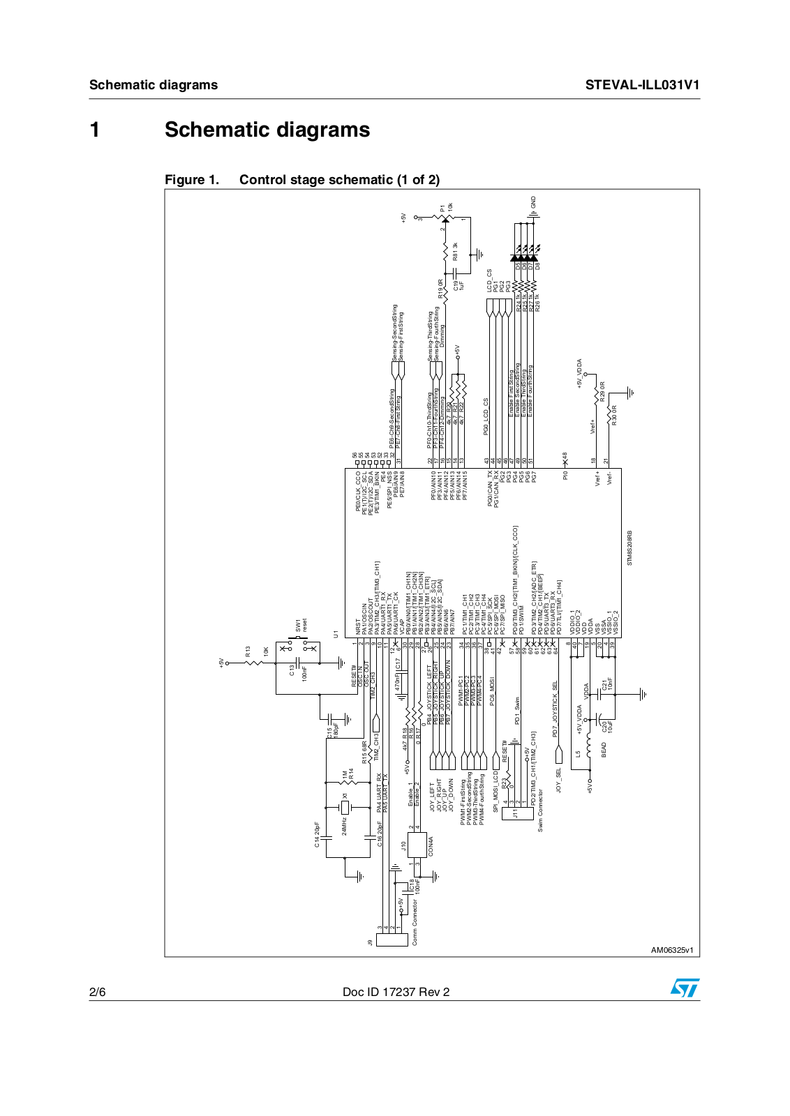
ILL031V1
Datasheet (ST)
6 pgs
142.92 Kb
0
Table of contents
Loading...
Datasheet ILL031V1 Datasheet (ST)
...
Datasheet Datasheet (ST)
Download
Specifications and Main Features
Frequently Asked Questions
User Manual
Download
Loading...
+
hidden pages
Unhide
You need points to download manuals.
1 point = 1 manual.
You can buy points or you can get point for every manual you upload.
Buy points
Upload your manuals
 Loading...

")