


PCG-F360

– 2 –PCG-F340/F350/F360 (UC)
Information in this document is subject to change without
notice.
Sony and VAIO are trademarks of Sony. Intel logo and Intel
Inside logo are registered trademarks of Intel Corporation.
Pentium MMX is a trademark of Intel Corporation. Microsoft,
MS-DOS, Windows, the Windows 95 and Windows 98 logo
are trademarks of Microsoft Corporation.
All other trademarks are trademarks or registered trademarks
of their respective owners. Other trademarks and trade names
may be used in this document to refer to the entitles claiming
the marks and names or their produces. Sony Corporation
disclaims any proprietary interest in trademarks and trade names
other than its own.
Service and Inspection Precautions
1. Obey precautionary markings and
instructions
Labels and stamps on the cabinet, chassis, and components identify
areas requiring special precautions. Be sure to observe these
precautions, as well as all precautions listed in the operating manual
and other associated documents.
2. Use designated parts only
The set’s components possess important safety characteristics, such
as noncombustibility and the ability to tolerate large voltages. Be
sure that replacement parts possess the same safety characteristics as
the originals. Also remember that the ! mark, which appears in
circuit diagrams and parts lists, denotes components that have
particularly important safety functions; be extra sure to use only the
designated components.
3. Always follow the original design when
mounting parts and routing wires
The original layout includes various safety features, such as inclusion
of insulating materials (tubes and tape) and the mounting of parts
above the printer board. In addition, internal wiring has been routed
and clamped so as to keep it away from hot or high-voltage parts.
When mounting parts or routing wires, therefore, be sure to duplicate
the original layout.
4. Inspect after completing service
After servicing, inspect to make sure that all screws, components,
and wiring have been returned to their original condition. Also check
the area around the repair location to ensure that repair work has caused
no damage, and confirm safety.
5. When replacing chip components...
Never reuse components. Also remember that the negative side of
tantalum capacitors is easily damaged by heat.
6. When handling flexible print boards...
•The temperature of the soldering-iron tip should be about 270C.
•Do not apply the tip more than three times to the same pattern.
•Handle patterns with care; never apply force.
Caution: Remember that hard disk drives are easily damaged by
vibration. Always handle with care.
Caution Markings for Lithium/Ion Battery - The following or
similar texts shall be provided on battery pack of equipment or
in both the operating and the service instructions.
CAUTION: Danger of explosion if battery is incorrectly
replaced. Replace only with the same or equivalent type
recommended by the manufacturer. Discard used batteries
according to the manufacturer’s instructions.
CAUTION: The battery pack used in this device may present a
fire or chemical burn hazard if mistreated. Do not disassemble,
heat above 100°C (212°F) or incinerate.
Dispose of used battery promptly.
Keep away from children.
ATTENTION AU COMPOSANT AYANT RAPPORT
À LA SÉCURITÉ!
LES COMPOSANTS IDENTIFÉS P AR UNE MARQUE ! SUR LES
DIAGRAMMES SCHÉMA TIQUES ET LA LISTE DES PIÈCES SONT
CRITIQUES POUR LA SÉCURITÉ DE FONCTIONNEMENT. NE
REMPLACER CES COMPOSANTS QUE PAR DES PIÈSES SONY
DONT LES NUMÉROS SONT DONNÉS DANS CE MANUEL OU
DANS LES SUPPÉMENTS PUBLIÉS PAR SONY.

– 3 – PCG-F340/F350/F360 (UC)
TABLE OF CONTENTS
CHAPTER 1. REMOVAL
1-1. Flowchart ......................................................................... 1-1
1-2. Main Electrical Parts Location Diagram ......................... 1-1
1-3. Removal ...........................................................................1-2
1. Hinge Cover .....................................................................1-2
2. Keyboard Unit, Palm Rest Housing Assy,
Assy Hood Keyboard....................................................... 1-2
3. Display Assy, CD-ROM Drive......................................... 1-3
4. DC Fan, SWX-28 Board ..................................................1-3
5. HDD Assy, PWS-5 (-2) Board, Latch Detector Unit,
SWX-30 (-2) Board ......................................................... 1-4
6. PC Card Connector, IFX-56 Board, CNX-50 Board,
MPM-12 Board, MBX-15 (-2) Board.............................. 1-4
7. Battery, Lithium............................................................... 1-5
8. Speaker Unit, SWX-29 Board ......................................... 1-5
9. LCD Section (F350/F360 MODEL)
(Made by Samsung) ......................................................... 1-6
1. Bezel Housing Assy, LCD Unit (14 inch),
Display Housing Assy, Inverter Assy ......................... 1-6
2. Hinge Left, Hinge Right, LCD Cable......................... 1-7
10.LCD Section (F350/F360 MODEL)
(Made by Hitachi) ............................................................ 1-8
1. Bezel Housing Assy, LCD Unit (14 inch),
Display Housing Assy, Inverter Assy ......................... 1-8
2. Hinge Left, Hinge Right, LCD Cable......................... 1-9
11.LCD Section (F340 MODEL) ........................................ 1-10
1. Bezel Housing Assy, LCD Unit (13 inch),
Display Housing Assy, Inverter Assy ....................... 1-10
2. Hinge Left, Hinge Right, LCD Cable....................... 1-11
(to 1-11)
Section Title Page
• Abbreviations
UC : US model / Canadian model
Section Title Page
CHAPTER 2. SELF DIAGNOSTICS
2-1. Required Tools and Peripheral Devices ........................... 2-1
2-2. Tools and Peripheral Device Connection......................... 2-3
2-3. How to Start the Diagnostics ........................................... 2-4
2-4. Test Items......................................................................... 2-4
1. Start Menu ....................................................................... 2-4
2. PCG-F3 Series Diagnostics ............................................. 2-4
3. Short Descriptions of the Test Items................................ 2-5
2-5. About the PASSWORD Bypass....................................... 2-8
(to 2-8)
CHAPTER 3. BLOCK DIAGRAM............................... 3-1
(to 3-2)
CHAPTER 4. FRAME HARNESS DIAGRAM........ 4-1
(to 4-2)
CHAPTER 5. EXPLODED VIEWS AND
PARTS LIST............................................ 5-1
5-1. Main Section ....................................................................5-2
5-2. LCD Section (F350/F360 MODEL) ................................5-5
1. LCD Made by Samsung ................................................... 5-5
2. LCD Made by Hitachi ..................................................... 5-7
5-3. LCD Section (F340 MODEL) ......................................... 5-9
(to 5-10)
1-1 PCG-F340/F350/F360 (UC)
CHAPTER 1.
REMOVAL
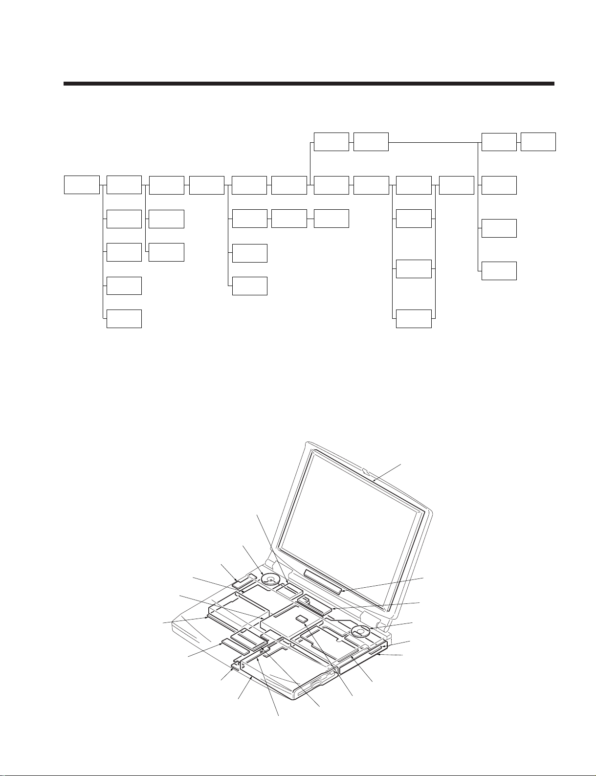
1-1. Flowchart
• P XX means pages that appears in this manual.
• Remember that hard disk drives are easily damaged by vibration. Always handle with care.
1-2. Main Electrical Parts Location Diagram
POWER
OFF
ASSY HOOD
KEYBOARD
BATTERY
LITHIUM
BATTERY
PACK
HINGE
COVER
KEYBOARD
UNIT
P 1-2P 1-2
P 1-5P 1-5
P 1-5
P 1-2
P 1-2 P 1-3
P 1-4
1 through 4
P 1-3
P 1-4
P 1-4
5 through 7
9 through !º
P 1-4
P 1-4
P ALM RESET
HOUSING
ASSY
CD-ROM
DRIVE
SWX-28
BOARD
P 1-3
DC
FAN
HDD
MPM-12
BOARD
PC CARD
CONNECTOR
BRACKET
BOTTOM
MBX-15 (-2)
BOARD
∗P 1-6
(P 1-8)
〈P 1-10〉
∗P 1-7
(P 1-9)
〈P 1-11〉
∗P 1-7
(P 1-9)
〈P 1-11〉
∗P 1-7
(P 1-9)
〈P 1-11〉
∗P 1-6
(P 1-8)
〈P 1-10〉
∗P 1-6
(P 1-8)
〈P 1-10〉
∗P 1-6
(P 1-8)
〈P 1-10〉
FDD
SPEAKER
UNIT
SWX-29
BOARD
P 1-3
DISPLAY
ASSY
P 1-4
5 through 7
!™ through !£
IFX-56
BOARD
P 1-4
5 through 8
!¡ through !™
CNX-50
BOARD
P 1-4
LCD
CABLE
INVERTER
ASSY
HINGE
LEFT
HINGE
RIGHT
DISPLAY
HOUSING
ASSY
BEZEL
HOUSING
ASSY
LCD
UNIT
PWS-5 (-2)
BOARD
P 1-4
LA TCH
DETECTOR
P 1-4
SWX-30 (-2)
BOARD
∗ : F350/F360 MODEL (Samsung)
( ) : F350/F360 MODEL (Hitachi)
〈 〉 : F340 MODEL
LCD Unit
Inverter Assy
Speaker Assy
CNX-50 Board
CD-ROM Drive (F340 Model)
or
DVD-ROM Drive
(F350/F360 Model)
IFX-56 Board
RO-27 Board
PWS-5 (-2) Board
FD Drive
SWX-30 (-2) Board
CNX-64 Board
MBX-15 (-2) Board
MPM-12 Board
SWX-28 Board
Speaker Assy
DC Fan
HDD
SWX-29 Board
Track Pad
1-2PCG-F340/F350/F360 (UC)
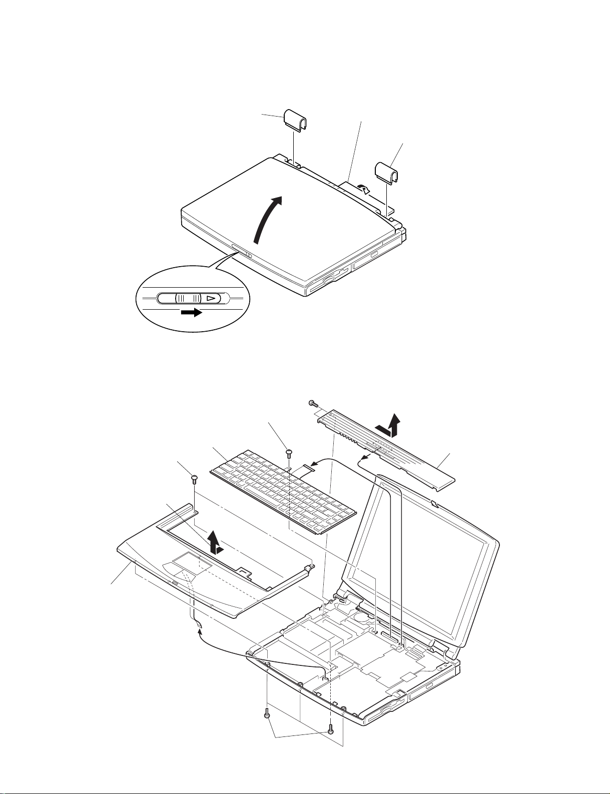
1-3.Removal
1. Hinge Cover
2. Keyboard Unit, Palm Rest Housing Assy, Assy Hood Keyboard
2Hinge Cover
1Door I/O
3
4
2Hinge Cover
Assy Hood Keyboard
Keyboard Unit
Palm Reset
Housing Assy
1M2X5 Special Head (X2)
4
3M2X4
6M2X4 Special Head
(X2)
5+P 2X16 (X4)
7Pull it to the front slightly
and raise to remove it.
2Pull it up sliding it
to the right.
1-3 PCG-F340/F350/F360 (UC)
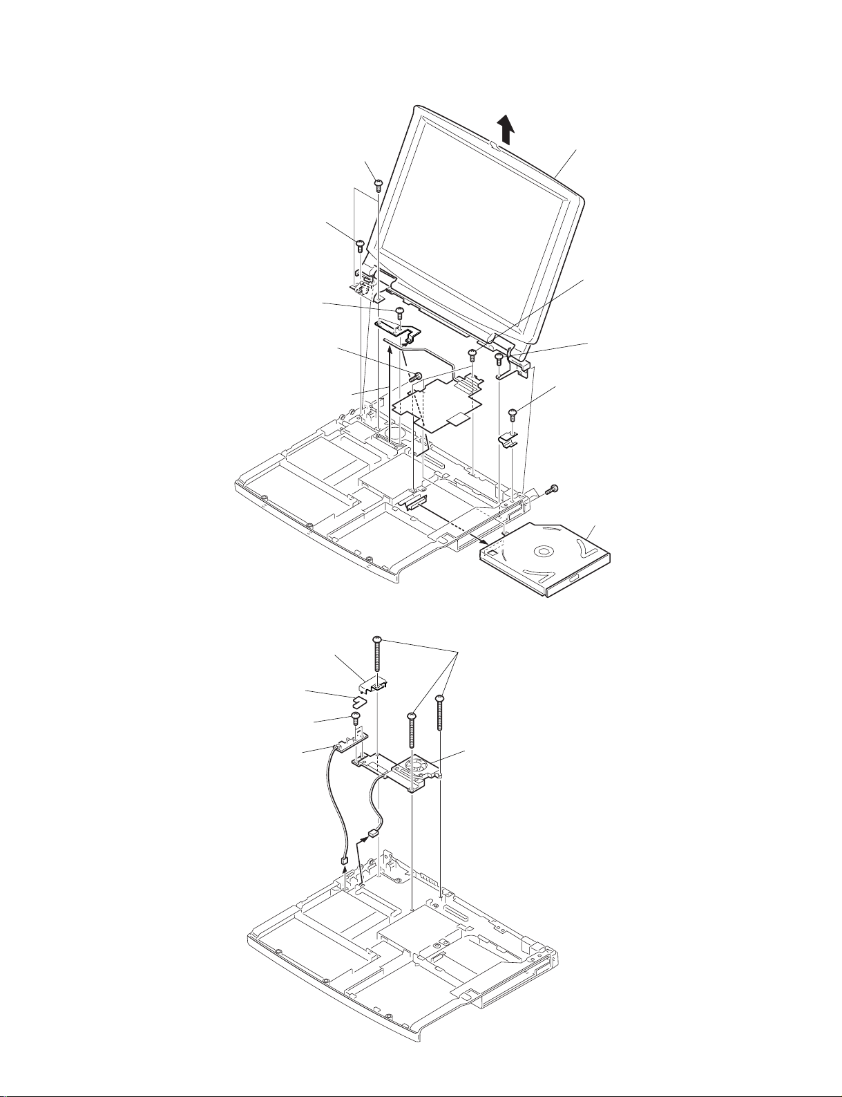
3. Display Assy, CD-ROM Drive
4. DC Fan, SWX-28 Board
Display Assy
CD-ROM Drive
4
6+PS 2X6
7+B 2.6X5
7+B 2.6X5
3
1Bolt (M2X2)
Spring (X3)
1Bolt (M2X2)
Spring
2M2X4 (X3)
5+PS 2X6
(X2)
6+PS 2X6
8
DC Fan
PW Sheet
IrDA Bracket
SWX-28 Board
3+B 2X16 (X3)
1M2X4 (X2)
4
2
1-4PCG-F340/F350/F360 (UC)
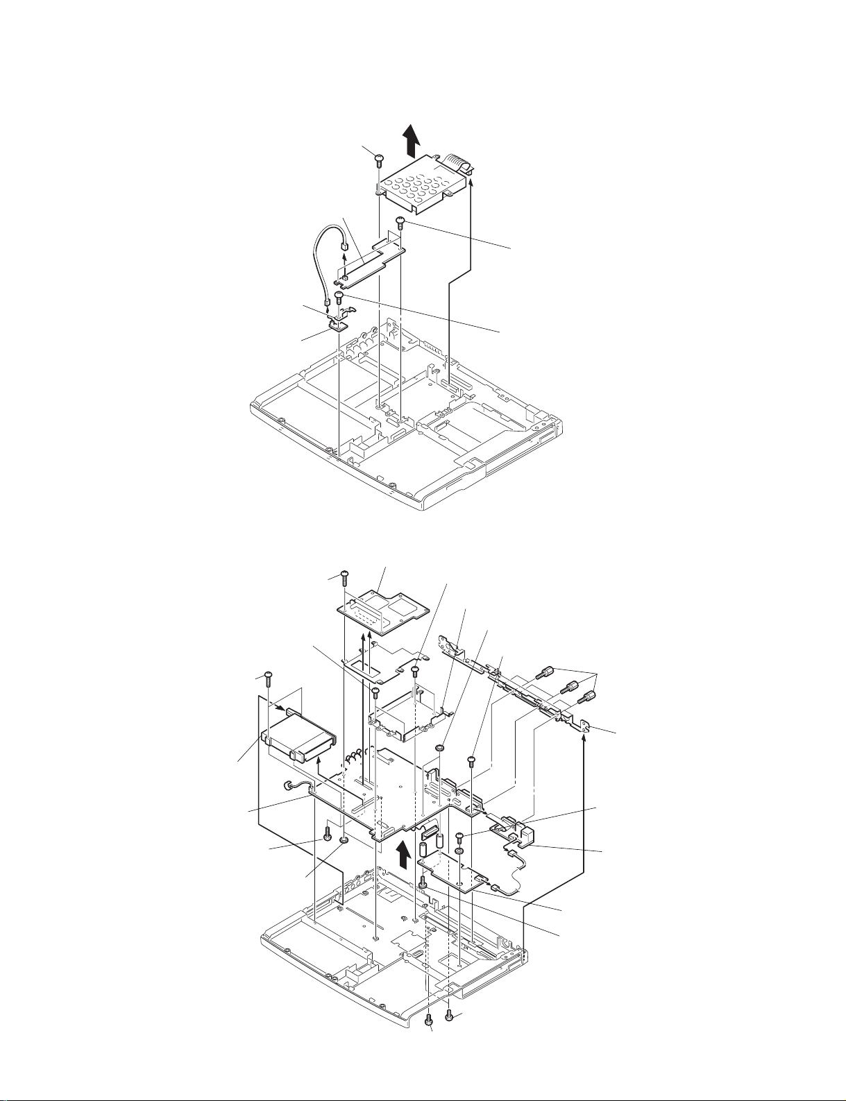
5. HDD Assy, PWS-5 (-2) Board, Latch Detector Unit, SWX-30 (-2) Board
6. PC Card Connector, IFX-56 Board, CNX-50 Board, MPM-12 Board, MBX-15 (-2) Board
6Flexible Connector
4PWS-5 (-2) Board
2SWX-30 (-2) Board
2Latch Detector Unit
7HDD Assy
5M2X4
3M2X4
1M2X4
MBX-15 (-2) Board
CNX-50 Board
IFX-56 Board
MPM-12 Board
4PC Card Connector
7+P 2X2.5 Type3
8M2X4 Special Head (X2)
!™Nut M2
(X2)
3+B 2X16 (X2)
!º+B 2X10 (X2)
2Bracket HDD
1+B M2 (X2)
1+B M2
6M2X4
5M2X4
I/O Bracket
!§Nut M2 (X2)
!¡Screw (HEX)
(X6)
9
!£
!™M2X9 (X2)
!§M2X6.5 (X2)
!∞
!¢
!∞
1-5 PCG-F340/F350/F360 (UC)
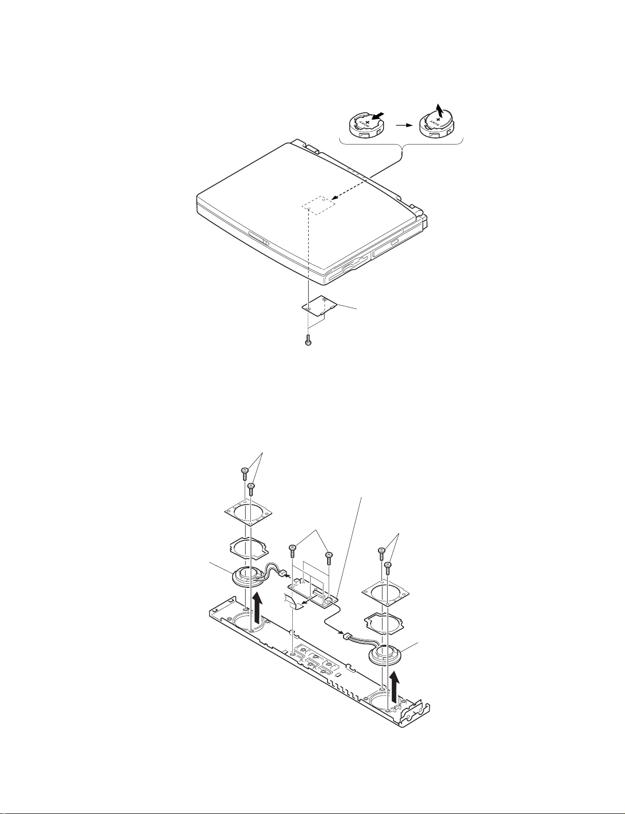
7. Battery, Lithium
8. Speaker Unit, SWX-29 Board
CR2025
CR2025
Flash Door
1+P 2X2.5 TYPE3 (X2)
Speaker Unit
SWX-29 Board
Speaker Unit
2M2X4 (X5)
1
1
1
3M2X4 (X2)
3M2X4 (X2)
1-6PCG-F340/F350/F360 (UC)
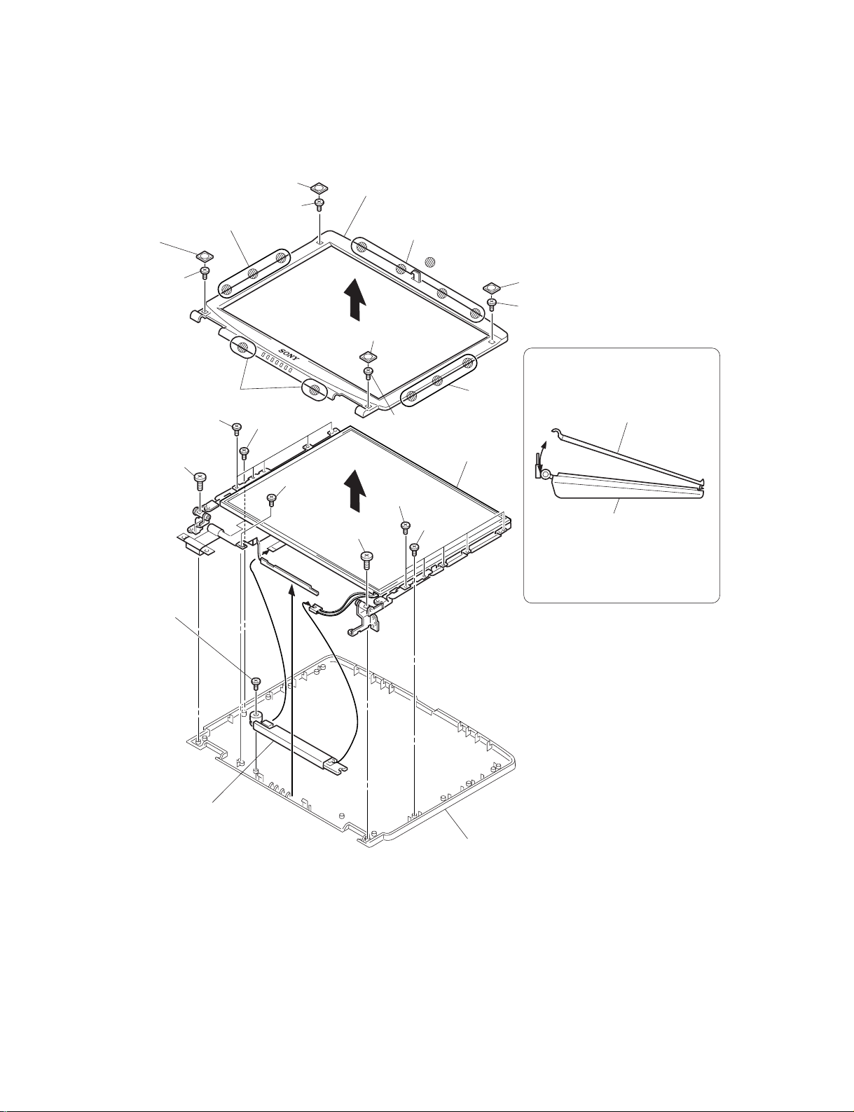
9. LCD Section (F350/F360 Model) (Made by Samsung)
1. Bezel Housing Assy, LCD Unit (14 inch), Display Housing Assy, Inverter Assy
Display Housing Assy
Inverter Assy
Bezel Housing Assy
LCD Unit
: claw part
a
b
c
b
!º
9
8
7
3
1Upper Screw Cover
1Upper Screw Cover
1Lower Screw
Cover
1Lower Screw
Cover
2M2X4
2M2X4
2M2X4
2M2X4
6+PS 2.6X5
6+PS 2.6X5
!¡M2X4
5M2X4
5M2X4 (X5)
5M2X4
4M2X4
Display Housing Assy
Bezel Housing Assy
a
Order of releasing the claws c → b → a
Order of locking the claws a → b → c
How to release the claw a
Turn the Bezel Housing
Assy as shown to release
the claw a.
5M2X4 (X5)
1-7 PCG-F340/F350/F360 (UC)
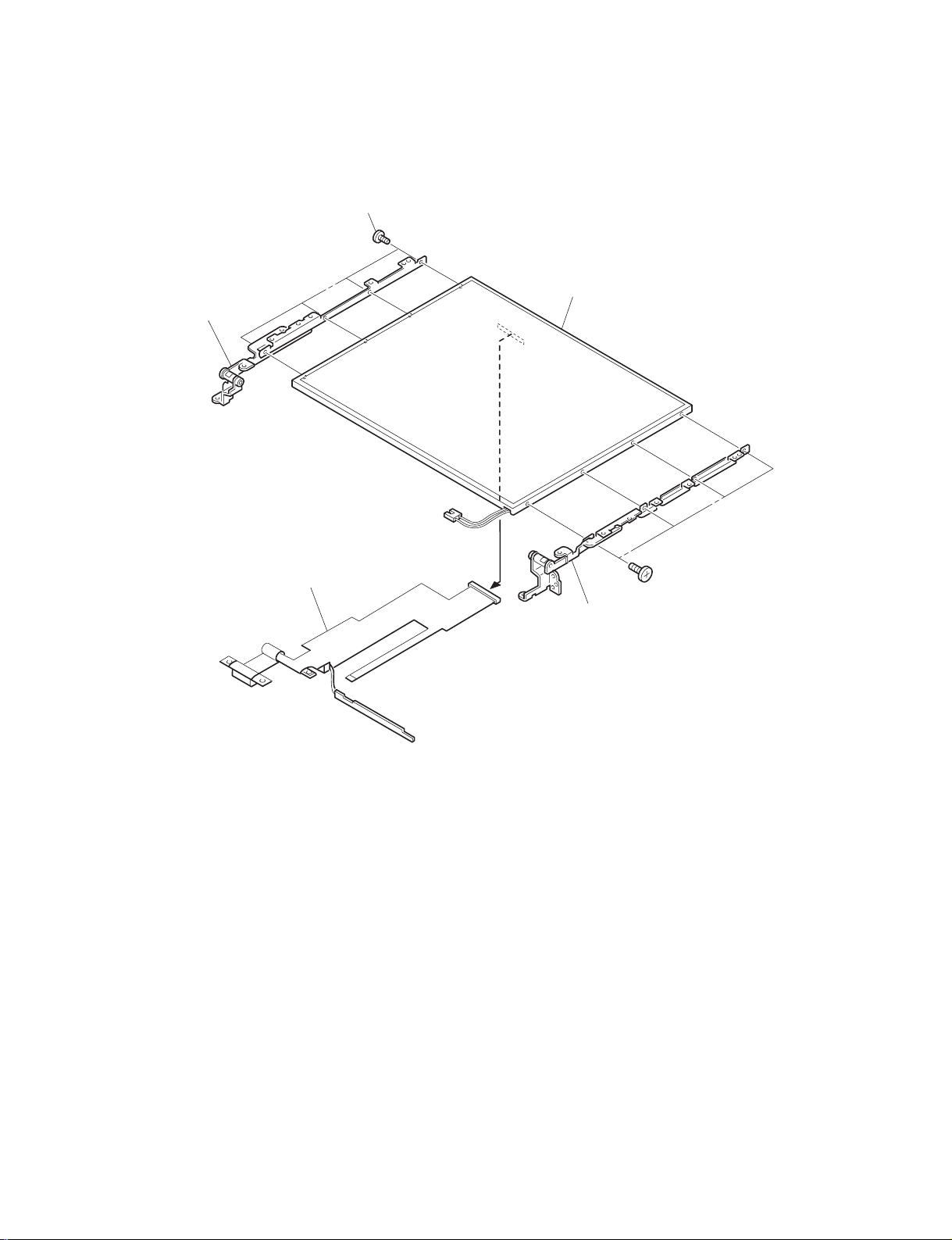
2. Hinge Left, Hinge Right, LCD Cable
Hinge Left
LCD Cable
LCD
Hinge Right
1M2X4 Special Head (X4)
1M2X4 Special Head (X4)
2
 Loading...