


IXS-6600
Table of contents
 Loading...
Sony IXS-6600, IXS-6600-C, IKS-A6012, IKS-A6013, IKS-A6015 Installation Manual
...
INTEGRATED ROUTING SYSTEM PACK
IXS-6600-C
IXS-6700-C
INTEGRATED ROUTING SYSTEM
IXS-6600
IXS-6700
IKS-6030M IKS-A6011 IKS-A6012
IKS-A6013 IKS-A6015 IKS-A6050
IKS-A6061 IKS-A6062 IKS-A6063
IKS-V6010M IKS-V6010SD IKS-V6050M
IKS-V6050SD IKS-V6060M IKS-V6060SD
IKS-RS6010 IKS-RS6060 IKS-TC6010
IKS-TC6060
INSTALLATION MANUAL
1st Edition (Revised 7)

! WARNING
This manual is intended for qualified service personnel only.
To reduce the risk of electric shock, fire or injury, do not perform any servicing other than that
contained in the operating instructions unless you are qualified to do so. Refer all servicing to
qualified service personnel.
! WARNUNG
Die Anleitung ist nur für qualifiziertes Fachpersonal bestimmt.
Alle Wartungsarbeiten dürfen nur von qualifiziertem Fachpersonal ausgeführt werden. Um die
Gefahr eines elektrischen Schlages, Feuergefahr und Verletzungen zu vermeiden, sind bei
Wartungsarbeiten strikt die Angaben in der Anleitung zu befolgen. Andere als die angegeben
Wartungsarbeiten dürfen nur von Personen ausgeführt werden, die eine spezielle Befähigung
dazu besitzen.
! AVERTISSEMENT
Ce manual est destiné uniquement aux personnes compétentes en charge de l’entretien. Afin
de réduire les risques de décharge électrique, d’incendie ou de blessure n’effectuer que les
réparations indiquées dans le mode d’emploi à moins d’être qualifié pour en effectuer d’autres.
Pour toute réparation faire appel à une personne compétente uniquement.
IXS-6700 Serial No. 10001 and Higher
IXS-6600 Serial No. 10001 and Higher
IKS-6030M Serial No. 10001 and Higher
IKS-A6011 Serial No. 10001 and Higher
IKS-A6012 Serial No. 10001 and Higher
IKS-A6013 Serial No. 10001 and Higher
IKS-A6015 Serial No. 10001 and Higher
IKS-A6050 Serial No. 10001 and Higher
IKS-A6061 Serial No. 10001 and Higher
IKS-A6062 Serial No. 10001 and Higher
IKS-A6063 Serial No. 10001 and Higher
IKS-V6010M Serial No. 10001 and Higher
IKS-V6010SD Serial No. 10001 and Higher
IKS-V6050M Serial No. 10001 and Higher
IKS-V6050SD Serial No. 10001 and Higher
IKS-V6060M Serial No. 10001 and Higher
IKS-V6060SD Serial No. 10001 and Higher
IKS-RS6010 Serial No. 10001 and Higher
IKS-RS6060 Serial No. 10001 and Higher
IKS-TC6010 Serial No. 10001 and Higher
IKS-TC6060 Serial No. 10001 and Higher
IXS-6600/6700

Attention-when the product is installed in Rack:
(For IXS-6600/IXS-6700)
For the customers in the Netherlands
Voor de klanten in Nederland
1. Prevention against overloading of branch circuit
When this product is installed in a rack and is
supplied power from an outlet on the rack, please
make sure that the rack does not overload the supply
circuit.
2. Providing protective earth
When this product is installed in a rack and is
supplied power from an outlet on the rack, please
confirm that the outlet is provided with a suitable
protective earth connection.
3. Internal air ambient temperature of the rack
When this product is installed in a rack, please make
sure that the internal air ambient temperature of the
rack is within the specified limit of this product.
4. Prevention against achieving hazardous
condition due to uneven mechanical loading
When this product is installed in a rack, please make
sure that the rack does not achieve hazardous
condition due to uneven mechanical loading.
5. Install the equipment while taking the operating
temperature of the equipment into consideration
For the operating temperature of the equipment, refer
to the specifications of the Operation Manual.
Hoe u de batterijen moet verwijderen, leest u in de
Onderhoudshandleiding.
Gooi de batterij niet weg maar lever deze in als klein
chemisch afval (KCA).
Für Kunden in Deutschland
Entsorgungshinweis: Bitte werfen Sie nur entladene
Batterien in die Sammelboxen beim Handel oder den
Kommunen. Entladen sind Batterien in der Regel dann,
wenn das Gerät abschaltet und signalisiert “Batterie
leer” oder nach längerer Gebrauchsdauer der Batterien
“nicht mehr einwandfrei funktioniert”. Um
sicherzugehen, kleben Sie die Batteriepole z.B. mit
einem Klebestreifen ab oder geben Sie die Batterien
einzeln in einen Plastikbeutel.
6. When performing the installation, keep the rear of
the unit 10 cm (4 inches) or more away from walls
in order to obtain proper exhaust and radiation of
heat.
For safety, do not connect the connector for peripheral
device wiring that might have excessive voltage to the
following port(s).
: NETWORK A, B connector
Follow the instructions for the above port(s).
IXS-6600/6700
1 (P)


Table of Contents
Manual Structure
Purpose of this manual ................................................................. 3
Related manuals ........................................................................... 3
Trademarks ................................................................................... 3
Terminology ................................................................................. 4
Contents ........................................................................................ 4
1. Installation
1-1. Installation Procedure ..................................................... 1-1
1-2. Operating Environment ..................................................1-2
1-3. Power Supply ..................................................................1-2
1-3-1. Power Specifications .............................................1-2
1-3-2. Recommended Power Cord ................................... 1-2
1-4. Installation Space (External dimensions) ....................... 1-3
1-4-1. IXS-6700 ............................................................... 1-3
1-4-2. IXS-6600 ............................................................... 1-4
1-5. Installing the Options ...................................................... 1-5
1-5-1. Installing the Plug-in Boards ................................. 1-7
1-5-2. Installing the Connector Board .............................1-9
1-5-3. Installing IKS-A6015 .......................................... 1-10
1-6. Rack Mounting ............................................................. 1-11
1-6-1. Precautions for Rack Mounting ........................... 1-11
1-6-2. Rack Mounting Procedure ................................... 1-11
1-7. Matching Connectors ....................................................1-13
1-8. Input and Output Signals of Connectors ....................... 1-14
1-8-1. IXS-6700, IXS-6600 ........................................... 1-14
1-8-2. IKS-A6011 .......................................................... 1-15
1-8-3. IKS-A6013 .......................................................... 1-17
1-8-4. IKS-A6061 .......................................................... 1-19
1-8-5. IKS-A6063 .......................................................... 1-20
1-8-6. IKS-RS6010/IKS-RS6060 ..................................1-22
1-9. System Connection ....................................................... 1-23
1-9-1. S-BUS Data Link ................................................1-23
1-9-2. Network Connection ........................................... 1-26
1-9-3. Synchronous Signal for the Audio Signal ...........1-27
1-10. Setting the On-Board Switches and
Description of LEDs .....................................................1-28
1-11. Setting the IP Address .................................................. 1-41
2. Service Information
2-1. Error Display .................................................................. 2-1
2-1-1. Front Panel Status .................................................. 2-1
2-1-2. Error Indications and Countermeasures ................ 2-4
2-1-3. CA Board Error Display ........................................ 2-7
2-2. Periodic Inspection and Maintenance .............................2-9
2-2-1. Cleaning ................................................................ 2-9
2-3. Lithium Battery ............................................................. 2-10
2-4. Data Backup .................................................................. 2-11
2-4-1. Connection .......................................................... 2-11
2-4-2. Installing BZR-20/BZR-25 ................................. 2-12
2-4-3. Uploading the Data .............................................. 2-13
2-4-4. Downloading the Data ......................................... 2-14
2-5. Troubleshooting ............................................................2-15
Appendix A Terminal No. Quick Reference List
IXS-6600/6700
1


Purpose of this manual
Related manuals
Manual Structure
This manual is the installation manual of Integrated Routing System IXS-6700/IXS6600 and the optional boards.
This manual is intended for use by trained system and service engineers, and
deicribes the information on installing the IXS-6700/IXS-6600.
Besides this Installation Manual, the following manuals are prepared for the IXS6700/IXS-6600 and the optional boards.
..
. Operation Manual (Supplied with IXS-6700/IXS-6600)
..
This manual describes the application and operation of IXS-6700/IXS-6600.
..
. System Setup Manual (Supplied with IXS-6700/IXS-6600)
..
This manual describes the software initialization or operation confirmation.
..
. Maintenance Manual (Available on request)
..
This manual describes the information that premises the parts level service
(adjustment, parts list, diagrams, etc.).
If this manual is required, please contact your local Sony Sales Office/Service
Center.
Trademarks
..
. Protocol Manual (Available on request)
..
This manual describes the protocol for controlling this unit.
The manual below is provided for the protocol that this unit can support.
If this manual is required, please contact your local Sony Sales Office/Service Center.
SONY ROUTING SWITCHER SYSTEM
REMOTE1 (S-BUS/ROT16) PROTOCOL and COMMAND SPECIFICATIONS
Part No.: 9-977-477-xx
SONY ROUTING SWITCHER SYSTEM
REMOTE2 (Cart++) PROTOCOL and COMMAND SPECIFICATIONS
Part No.: 9-967-261-2x
Trademarks and registered trademarks used in this manual are follows.
. Ethernet is a registered trademark of Xerox Corporation.
. IBM and AT are registered trademarks of International Business Machines
Corporation.
. Pentium is a registered trademark of Intel Corporation.
. Windows is a registered trademark of Microsoft Corporation.
IXS-6600/6700
3

Terminology
Contents
. Routing Switcher
Indicates the name of the product category.
. Integrated Routing Switcher (IXS-6600/IXS-6700)
This is the product name of IXS-6600/IXS-6700. The product category of the
Integrated Routing Switcher belongs to Routing Switcher.
. Routing Switcher System
Indicates the configuration where multiple devices are connected to the Routing
Switcher. (Refer to “1-9. System Connection”.)
The following is a summary of all the sections of this manual.
Section 1 Installation
This section describes the installation procedure, operating environment, power
supply, installation space, installing the options, rack mounting, connectors, input
and output signals of connectors, system connection, and on-board switch/LED.
Section 2 Service Information
This section describes the error display, periodic inspection and maintenaance,
lithium battery, data backup, troubleshooting.
Appendix A Terminal No. Quick Reference List
This section describes the terminal No. quick reference list for each I/O connector.
4
IXS-6600/6700
Section 1
Installation
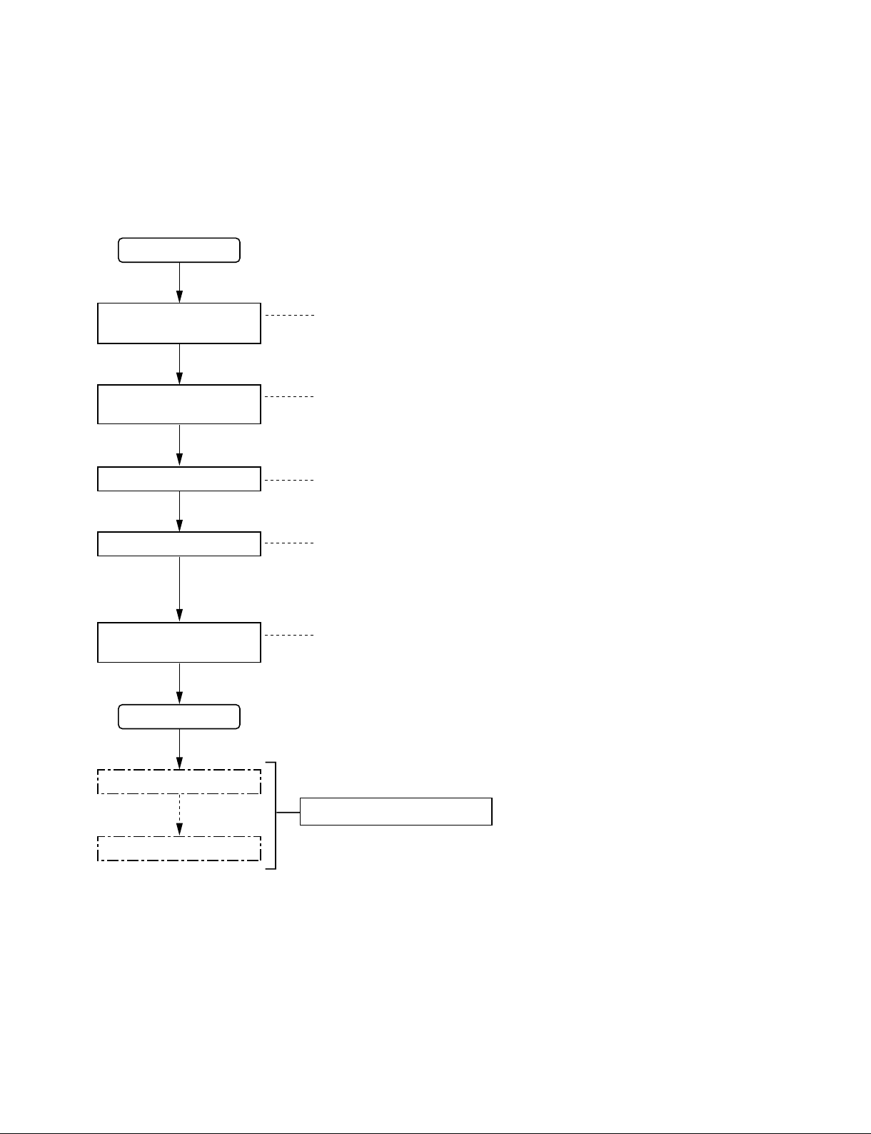
1-1. Installation Procedure
The following chart shows the procedure for installing the unit.
For details of the following chart, refer to the relevant section or related manual.
Start
Operating Environment
Selection of installation
place
Installation of optional
boards
1-2.
Power Supply
1-3.
Installation Space
1-4.
Installing the Options
1-5.
Rack mounting
Connection
Setting the On-Board
Switches
End
Initial setting
Operation check
Rack Mounting
1-6.
Matching Connectors
1-7.
Input and Output Signals of Connectors
1-8.
System Connection
1-9.
Setting the On-Board Switches and
1-10.
Description of LEDs
System Setup Manual
IXS-6600/6700
1-1
1-2. Operating Environment
Operating guaranteed temperature : +5 dC to +40 dC
Performance guaranteed temperature : +10 dC to +35 dC
Operating humidity : 10 % to 90 %
(relative humidity)
Storage temperature : _20 dC to +60 dC
Mass (when all options are installed) :
IXS-6700 : Approx. 41 kg
IXS-6600 : Approx. 24 kg
Prohibited locations for installation
. Areas where the unit will be exposed do direct sunlight
or any other strong lights.
. Dusty areas
. Areas subject to vibration.
. Areas with strong electric or magnetic fields.
. Areas near heat sources.
. Areas subject to electrical noise.
. Areas subject where is subjected to static electricity.
m
. As the inrush current at turn-on is a maximum of 145 A
(at 100 V)/110 A (at 240 V) with the IXS-6700, or a
maximum of 100 A (at 100 V)/100 A (at 240 V) with the
IXS-6600, the capacity of the AC power source must be
commensurate with this load.
If the capacity of the AC power is not adequately large,
the AC power source breaker will operate or the unit will
abnormally operate.
. The IXS-6700 contains the four power supply units as
the standard configuration.
The units A1 and B1, and the units A2 and B2 perform
the backup operation for the two main power supply
systems respectively totaling four power supply systems.
Therefore, turn ON the power of all four units when
starting up the system.
. The IXS-6600 contains the two power supply units as
the standard configuration.
The units A and B perform the backup operation for the two
main power supply systems respectively. Therefore, turn
ON the power of all two units when starting up the system.
Ventilation
The inside of the IXS-6700-C/IXS-6600-C (IXS-6000
series hereafter) is cooled by a fan (both sides).
The power supply can be damaged if the exhaust vent
(both sides) and air intake (front panel) are blocked or the
fan is stopped.
Therefore, leave a blank space of more than 10 cm in the
front and both sides of the IXS-6000 series.
1-3. Power Supply
1-3-1. Power Specifications
A switching regulator is used for the power supply of this
unit. The voltage within the range of 100 V to 240 V can
be used without changing the supply voltage.
Power requirements : AC 100 to 240 V
Power frequency : 50/60 Hz
Current consumption (at the time of full options installation) : IXS-6700 : 9.8 to 4.5 A
IXS-6600 : 6 to 2.5 A
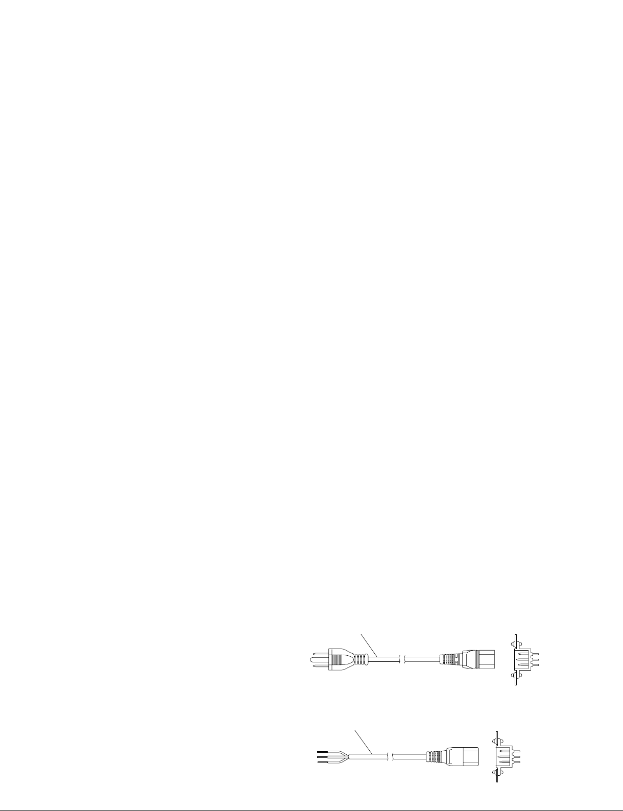
1-3-2. Recommended Power Cord
w
. Use the approved Power Cord (3-core mains lead)/Appli-
ance Connector/Plug with earthing-contacts that conforms
to the safety regulations of each country if applicable.
. Use the Power Cord (3-core mains lead)/Appliance
Connector/Plug conforming to the proper ratings (Voltage, Ampere).
If you have questions on the use of the above Power Cord/
Appliance Connector/Plug, please contact your local Sony
Sales Office/Service Center.
c
. Never use an injured power cord.
. Plugging the power cord in the AC inlet, push as far as it
will go.
For customers in the U.S.A. and Canada
1 Power cord, 125 V 10 A, 2.4 m (8 ft) : ! 1-557-377-11
1
For customers in the all European countries
1 Power cord, 250 V 10 A, 2.4 m (8 ft) : ! 1-782-929-22
AC inlet
1-2
1
AC inlet
IXS-6600/6700
1-4. Installation Space (External dimensions)
1-4-1. IXS-6700
B3
B3
18
B3
B3
52010
B3
B3
33
B3B3
144.5 115.5 115.5
61 370
339
482
465
440
4
37.6279.4
4
IXS-6600/6700
354(8U)
4
4
375
17.5
Unit : mm
1-3

1-4-2. IXS-6600
18
482
465
440
520
7
10
37.2101.6
176(4U)
161
380
ø26
144.5 115.5 115.5
61
1-4
375
482
17.5
Unit : mm
IXS-6600/6700

1-5. Installing the Options
The IXS-6700-C/IXS-6600-C is shipped from the factory with the necessary option boards (refer to the
following table) already installed in accordance with the specified system configuration.
c
The usable optional board is different depending on the type of signal to handle.
. The IKS-xxxxM series are the optional boards that can support the multi-bit rate signal including the
HDTV SDI signal. When a system has a chance to handle the HDTV SDI signal, be sure to use the
IKS-xxxxM series for all of the optional boards starting from INPUT through OUTPUT.
Signal type INPUT board Processor board Matrix board OUTPUT board
HDTV SDI signal IKS-V6010M IKS-V6050M IKS-6030M IKS-V6060M
SDTV SDI signal IKS-V6010SD IKS-V6050SD IKS-6030M IKS-V6060SD
AES/EBU signal IKS-A6011 IKS-A6050 IKS-6030M IKS-A6061
IKS-A6012 IKS-A6062
IKS-A6015
ANALOG AUDIO signal IKS-A6013 IKS-A6050 IKS-6030M IKS-A6063
RS-422A signal IKS-RS6010 IKS-A6050 IKS-6030M IKS-RS6060
TIME CODE (LTC) signal IKS-TC6010 IKS-A6050 IKS-6030M IKS-TC6060
* : This board cannot be used stand-alone. Be sure to use the IKS-A6015 board together with IKS-A6011 or IKS-A6012. This board
cannot be used for IKS-A6013.
*
IKS-V6050M
IKS-V6050SD
IXS-6600/6700
1-5

IXS-6700/IXS-6600 Option List
The following options are available for the IXS-6700/IXS-6600.
Model name Board configuration
Plug-in board
IKS-6030M MX-112 Board _
Matrix Board
IKS-V6050M DVP-39A Board _
HD/SD Video Router Processor Board
IKS-V6050SD DVP-39B Board _
SD Video Router Processor Board
IKS-V6010M _ CNI-24A Board
16 HD/SD Digital Video Input Board
IKS-V6060M _ CNO-26A Board
17 HD/SD Digital Video Output Board
IKS-V6010SD _ CNI-24B Board
16 SD Digital Video Input Board
IKS-V6060SD _ CNO-26B Board
17 SD Digital Video Output Board
IKS-A6050 DAP-39 Board _
Audio/Data Router Processor Board
IKS-A6011 _ CNI-26 Board
32 D-sub AES/EBU Input Board
IKS-A6012 _ CNI-28 Board
16 BNC AES/EBU Input Board
IKS-A6013 _ CNI-30 Board
Analog Audio Input Board
IKS-A6015 _ CNI-27 Board
32 Sampling Rate Converter Board
IKS-A6061 _ CNO-28 Board
34 D-sub AES/EBU Output Board
IKS-A6062 _ CNO-29 Board
17 BNC AES/EBU Output Board
IKS-A6063 _ CNO-31 Board
Analog Audio Output Board
IKS-RS6010 _ CNI-29 Board
7 RS-422 Input Board
IKS-RS6060 _ CNO-30 Board
7 RS-422 Output Board
IKS-TC6010 _ CNI-31 Board
16 Time Code Input Board
IKS-TC6060 _ CNO-32 Board
17 Time Code Output Board
Connector board
1-6
IXS-6600/6700
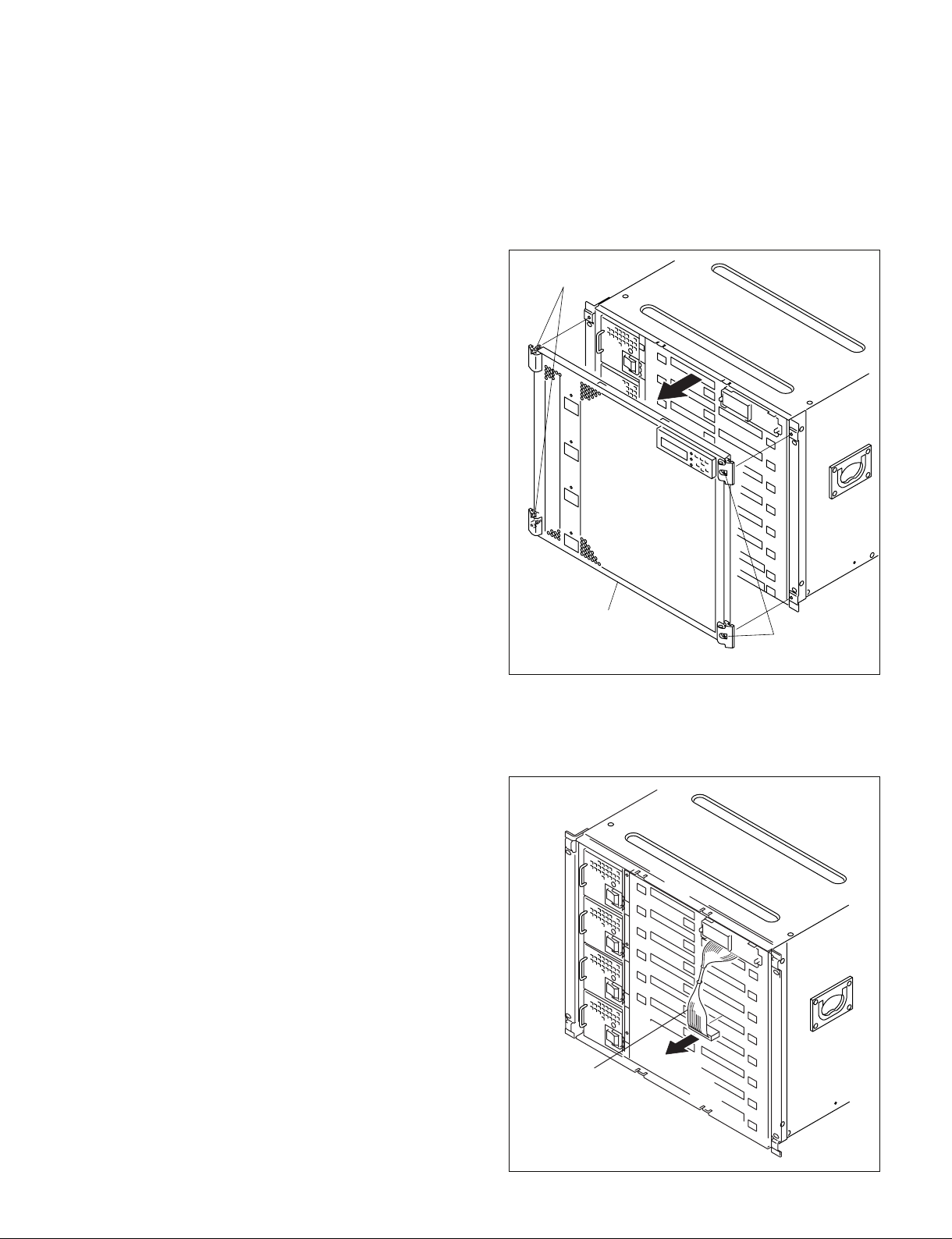
1-5-1. Installing the Plug-in Boards
Screws
(with drop-safe)
Front panel
Screw (with
drop-safe)
(The illustration shows the IXS-6700.)
c
Be sure to turn off the POWER switch before starting
installation work.
If installation work is started with the POWER switch left
on, it may cause electrical shock or damage to printed
circuit boards.
Each plug-in board of the Integrated Routing System IXS6700/IXS-6600 is allocated to a specific slot into which
they must be installed. Check to see that the respective
plug-in boards are installed in their respective slots.
The name of the board is shown near the eject lever at the
right-most end of each plug-in board.
Names of the printed circuit boards and the slot numbers,
to which the plug-in boards are allocated, are shown on the
Extract PWB stopper
IXS-6700/IXS-6600. Install the respective plug-in boards
according to this instruction.
m
Check that connectors of the plug-in boards are securely
inserted into the mother board (IXS-6700 : MB-1085
board, IXS-6600 : MB-1086 board) without loose contact.
If any plug-in board is inserted into the incorrect slot, it
causes a system error and the system will not work correctly.
assembly inside the front panel of the
Installation Procedure
1. Turn off the main power of this unit (IXS-6700 or
IXS-6600) and disconnect the AC power cord from the
outlet.
2. Loosen the four screws (with drop-safe) and remove
the front panel to the arrow.
3. Remove the harness connecting between the front display
and the IF-20.
IXS-6700 IF-20 Slot 4
IXS-6600 IF-20 Slot 2
IXS-6600/6700
Harness
(The illustration shows the IXS-6700.)
1-7
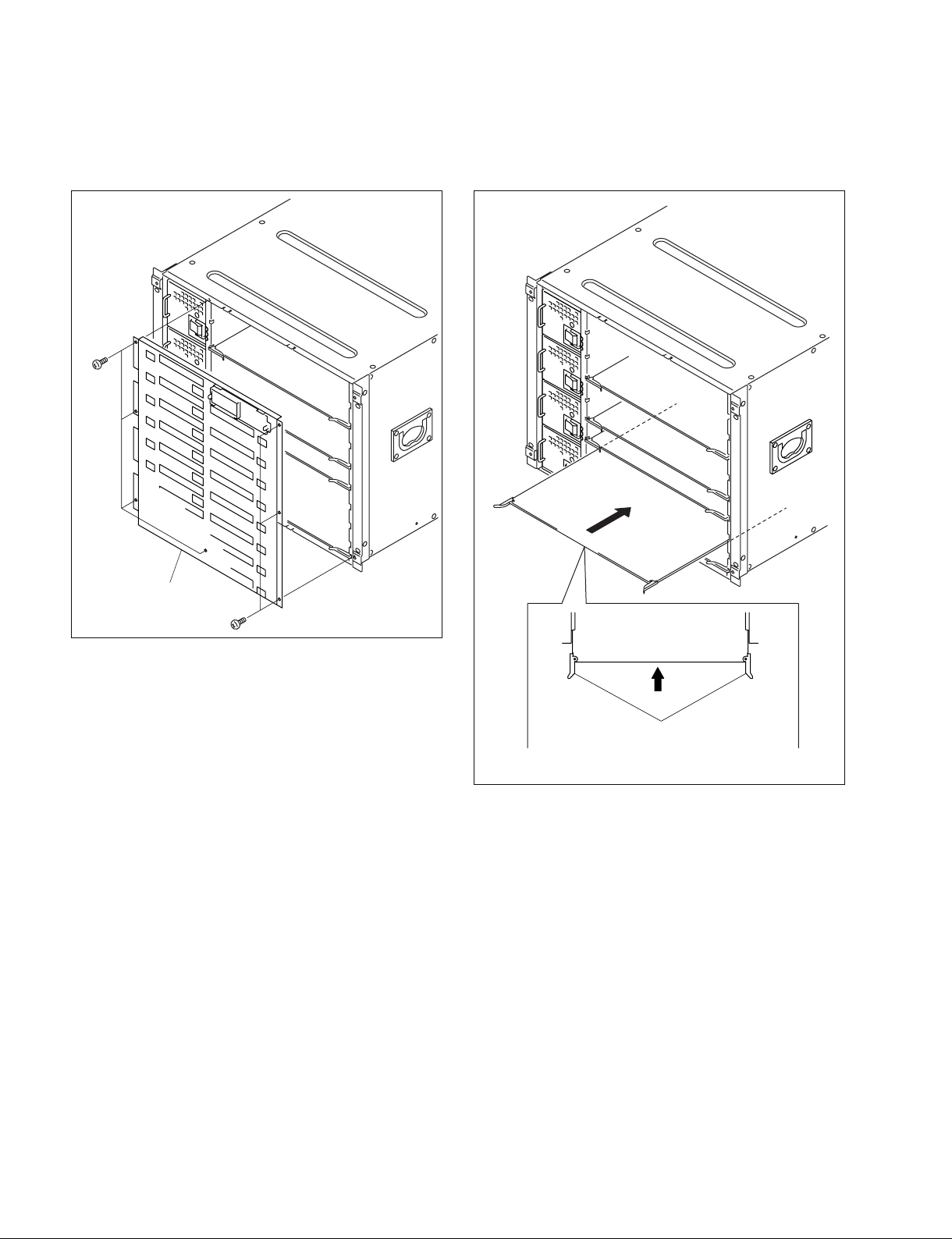
4. Remove the fixing screws (IXS-6700: 7 screws,
: 5 screws) and remove the Extract PWB stopper
6600
IXS-
assembly.
B3 x 5
5. While the eject levers are opened as shown in the
illustration, insert the plug-in board into the board
guide rail.
Extract PWB stopper
assembly
B3 x 5
(The illustration shows
the IXS-6700.)
Eject levers
(The illustration shows the IXS-6700.)
1-8
IXS-6600/6700

B3 x 5
B3 x 5
Blank panel
(The illustration shows the IXS-6700.)
Connector board
Screw
(with drop-safe)
Screw
(with drop-safe)
(The illustration shows the IXS-6700.)
6. While closing the eject levers in the direction of arrow
1, push in the plug-in board.
1-5-2. Installing the Connector Board
1. Remove the two screws and remove the blank panel.
n
Store the removed blank panel in a safe place.
1
Eject lever Eject lever
(The illustration shows the IXS-6700.)
1
7. Attach the Extract PWB stopper assembly and the
front panel by reversing the installation steps of 2, 3.
IXS-6700 option
Name of option Name of board
IKS-V6050M DVP-39A board 1, 3, 5, 7
IKS-V6050SD DVP-39B board 1, 3, 5, 7
IKS-A6050 DAP-39 board 1, 3, 5, 7
IKS-6030M MX-112 board 2, 6
Slot on the front side
IXS-6600 option
Name of option Name of board
IKS-V6050M DVP-39A board 1, 4
IKS-V6050SD DVP-39B board 1, 4
IKS-A6050 DAP-39 board 1, 4
IKS-6030M MX-112 board 3
IXS-6600/6700
Slot on the front side
2. Insert the connector board horizontally and secure it
with the two fixing screws.
1-9

IXS-6700 option
1-5-3. Installing IKS-A6015
Name of option Name of board
IKS-V6010M CNI-24A board IN1 to IN8
IKS-V6060M CNO-26A board OUT1 to OUT8
IKS-V6010SD CNI-24B board IN1 to IN8
IKS-V6060SD CNO-26B board OUT1 to OUT8
IKS-A6011 CNI-26 board IN1 to IN8
IKS-A6012 CNI-28 board IN1 to IN8
IKS-A6013 CNI-30 board IN1 to IN8
IKS-A6015
IKS-A6061 CNO-28 board OUT1 to OUT8
IKS-A6062 CNO-29 board OUT1 to OUT8
IKS-A6063 CNO-31 board OUT1 to OUT8
IKS-RS6010 CNI-29 board IN1 to IN8
IKS-RS6060 CNO-30 board OUT1 to OUT8
IKS-TC6010 CNI-31 board IN1 to IN8
IKS-TC6060 CNO-32 board OUT1 to OUT8
*
CNI-27 board _
Slot on the rear side
IXS-6600 option
Name of option Name of board
IKS-V6010M CNI-24A board IN1 to IN4
IKS-V6060M CNO-26A board OUT1 to OUT4
IKS-V6010SD CNI-24B board IN1 to IN4
IKS-V6060SD CNO-26B board OUT1 to OUT4
IKS-A6011 CNI-26 board IN1 to IN4
IKS-A6012 CNI-28 board IN1 to IN4
IKS-A6013 CNI-30 board IN1 to IN4
IKS-A6015
IKS-A6061 CNO-28 board OUT1 to OUT4
IKS-A6062 CNO-29 board OUT1 to OUT4
IKS-A6063 CNO-31 board OUT1 to OUT4
IKS-RS6010 CNI-29 board IN1 to IN4
IKS-RS6060 CNO-30 board OUT1 to OUT4
IKS-TC6010 CNI-31 board IN1 to IN4
IKS-TC6060 CNO-32 board OUT1 to OUT4
* : Install the CNI-27 board (IKS-A6015) to the CNI-26 board (IKS-A6011)
or the CNI-28 board (IKS-A6012).
*
CNI-27 board _
Slot on the rear side
IKS-A6015 is used by being mounted on IKS-A6011
(CNI-26 board) or IKS-A6012 (CNI-28 board).
1. Connect the IKS-A6015 to the connector (CN501) on
the IKS-A6011 or IKS-A6012.
n
Insert it to the deep end securely.
2. Fix the IKS-A6015 securely with the four screws
supplied.
PSW3 x 6
CN1
IKS-A6015
CN501
IKS-A6011
(The illustration shows the IKS-A6011.)
1-10
IXS-6600/6700

1-6. Rack Mounting
PS4 x 8
PS4 x 8
Feet
Feet
(The illustration shows the IXS-6700.)
B4 x 6
B4 x 6
Rack tool
Rack tool
(The illustration shows the IXS-6700.)
1-6-2. Rack Mounting Procedure
The IXS-6700/IXS-6600 is mounted in the 19-inch standard
rack. To mount the IXS-6700/IXS-6600 in the rack, use the
specified rack mount kit and follow the procedure described
below.
Specified rack mount kit : RMM-10
n
If a rack mount kit other than the one specified is used, the
unit may not be able to be mounted in the 19-inch standard
rack.
Parts of the RMM-10N
. Rack tool 2 pcs
. Right rack mount adapter 1 pc
. Left rack mount adapter 1 pc
. Rack tool attaching screw 6 pcs
(B4 x 6 : 7-682-560-09)
. Adapter attaching screw 6 pcs
(B4 x 10 : 7-682-560-10)
Other required parts
To mount the unit in the rack, rack mount kit RMM-10 and
the following part are required.
. Screw for rack mounting 4 pcs
(B5 x 12 : 7-682-576-04)
1-6-1. Precautions for Rack Mounting
w
.
To prevent the rack from falling or moving, fix the rack on
a flat and steady floor and the like using bolts or others.
If the rack falls due to the weight of the equipment, it may
cause death or serious injury.
. Be sure to use the specified rack mount kit.
If not, injury may result and the equipment may fall due
to insufficient strength.
. After rack mounting, be sure to tighten the screws on the
rack angle and fix the unit in the rack.
If the screws on the rack angle are not tightened, the unit
may slip from the rack and fall, causing injury.
This section describes the rack mounting procedure using
the RMM-10 rack mount kit.
1. Loosen the four screws (PS4 x 8) and remove the four
feet from the bottom of the equipment.
2. Attach the rack tool to the side of the equipment using
the specified six screws.
n
Use B4 x 6 screws.
Tighten the screws to the following torque.
Tightening torque : 120 x 10_2 N.m {12.2 kgf.cm}
c
When mounting the unit in the rack, note the following:
. Be sure to mount in the rack with two persons or more.
. Be careful not to catch your fingers or hands in the rack
mount rail or others.
. Mount in the rack in a steady posture.
n
If several units are mounted in a rack, it is recommended to
install a ventilation fan to prevent temperature rise inside
the rack.
IXS-6600/6700
1-11

3. Loosen the screws on the rear of the right and left
adapters and adjust the length of the adapter according
to the depth of the rack.
(The illustration below shows the left adapter.)
Adapter
7. Align the groove of the rack tools at the sides of the
equipment with the rail, and slide the equipment to the
rear.
n
The rack tools are hooked on the rails as shown below.
Portion of
the rail
B4 x 6
B4 x 6
n
Maximum depth of adapter : 750 mm
Minimum depth of adapter : 595 mm
4. Attach the right and left adapters to the rack completely using the specified six screws.
(The illustration below shows the left adapter.)
Rack tool
Rail Rail
Rack tool
8. Fix the rack angle in the rack using the specified
screws.
B5 x 12
8U
B4 x 10
4U
1U
31.75
31.75
B4 x 10
Unit : mm
5. Tighten the screws (B4 x 6 : two screws each on the
right and left) for adjusting the length of the adapter
completely (the screws that were loosened in step 3).
6. Remove the front panel of the equipment.
(Refer to Section 1-5-1.)
1-12
(The illustration shows the IXS-6700.)
B5 x 12
9. Attach the front panel to the equipment.
(Refer to Section 1-5-1.)
IXS-6600/6700

1-7. Matching Connectors
Use the following connectors and cables, or equivalents when connecting cables to the unit.
Model name Panel indication Connector name Matching connector and cable
Name Sony part No.
IKS-6010M INPUT 1 to 16 BNC, 75 Z Belden 8281 coaxial _
IKS-6060M OUTPUT 1 to 17 cable (SDTV system)
IKS-6010SD INPUT 1 to 16 BNC, 75 Z Belden 8281 coaxial _
IKS-6060SD OUTPUT 1 to 17 cable (SDTV system)
IKS-A6011 AES/EBU INPUT 1 to 12, 13 to 24 D-sub 37-pin, Female Digital audio cable
IKS-A6061 AES/EBU OUTPUT 1 to 12, 13 to 24 (110 Z) Canare Electric
AES/EBU INPUT 25 to 32 D-sub 25-pin, Female Digital audio cable
AES/EBU OUTPUT 25 to 32 (110 Z) Canare Electric
AES/EBU OUTPUT 33 to 34 D-sub 9-pin, Female Digital audio cable
IKS-A6012 AES/EBU INPUT 1 to 16 BNC, 75 Z Belden 8281 coaxial _
IKS-A6062 AES/EBU OUTPUT 1 to 17 cable (SDTV system)
IKS-A6013 ANALOG AUDIO INPUT 1 to 4, D-sub 25-pin, Female D-sub 25-pin, Male
5 to 8, 9 to 12, 13 to 16 Connector 25-pin, Male 1-566-356-11
IKS-A6063 ANALOG AUDIO OUTPUT 1 to 4, Junction Shell 25-pin
5 to 8, 9 to 12, 13 to 16
IKS-RS6010 RS-422 INPUT 1 to 7 D-sub 9-pin, Female D-sub 9-pin, Male
IKS-RS6060 RS-422 OUTPUT 1 to 7 Connector 9-pin, Male 1-566-354-21
IXS-6700 REF IN A, B BNC, 75 Z Belden 8281 coaxial _
IXS-6600 WORD SYNC IN A, B
WORD SYNC IN
*5
*6
REMOTE-1A, 1B*6, 1B1*5, 1B2*5, 1C Belden 1694 coaxial
TIMECODE IN cable (HDTV system)
REMOTE 2A, 2B
REMOTE 2
REMOTE 2/ALARM
*5
*6
*6
D-sub 9-pin, Female D-sub 9-pin, Male
REMOTE 3 D-sub 9-pin, Male D-sub 9-pin, Female
*5
ALARM
NETWORK A, B RJ-45 modular jack
D-sub Mini 15-pin, Female D-sub Mini 15-pin, Male _
*4
IKS-TC6010 TIMECODE INPUT 1 to 16 BNC, 75 Z Belden RG-59U coaxial _
IKS-TC6060 TIMECODE OUTPUT 1 to 17 cable
or
Belden 1694 coaxial
cable (HDTV system)
DA202 or equivalent
*7
D-sub 37-pin, Male
Connector 37-pin, Male 1-566-357-11
Junction Shell 37-pin
DA202 or equivalent
*7
*8*9
1-563-378-11
D-sub 25-pin, Male
Connector 25-pin, Male 1-566-356-11
Junction Shell 25-pin
(110 Z) Canare Electric
DA202 or equivalent
*7
*8*9
1-563-377-11
D-sub 9-pin, Male
Connector 9-pin, Male 1-566-354-21
Junction Shell 9-pin
Junction Shell 9-pin
*8*9
*8
*8, *10
1-563-375-11
1-563-377-11
1-563-375-11
cable (SDTV system)
or
Connector 9-pin, Male 1-566-354-21
Junction Shell 9-pin
Connector 9-pin, Female 1-563-815-21
Junction Shell 9-pin
*8
*8
1-563-375-11
1-563-375-11
__
*10
*1
*1
*2
*2
*2
*2
*3
*1 : The following crimp contact is required for the plug.
AWG#18 to #22 : 1-566-493-21
AWG#22 to #24 : 1-564-774-11
AWG#24 to #30 : 1-564-775-11
*2 : The following crimp contact is required for the plug.
AWG#20 to #24 : 1-566-352-11
AWG#24 to #28 : 1-566-353-11
*3 : The following crimp contact is required for the plug.
AWG#24 to #26 : 1-563-814-11
*4 : Conforms to the IEEE 802.3 Ethernet 100BASE-TX standards.
IXS-6600/6700
*5, *6 : Only IXS-6700
*7 : For the digital audio cable (110 Z), DA202 manufactured by Canare
Electric or equivalent is recommended.
• Shield (braided) density: 95% or more
• Shield DCR: 2.0 Z or less/100m
• Outer diameter: 5 mm or less
*8 : Use a junction shell of height 15 mm or less.
*9 : DC24660 manufactured by JAE or equivalent is recommended.
*10 : For BNC-XLR connector conversion, directly connecting the connector
shells (frame GND) is recommended.
1-13

1-8. Input and Output Signals of
_ EXT VIEW _
1
5
11
15
6
10
Connectors
The input and output signals of the connectors at the rear
panel are as follows.
ALARM
(*1)
: D-sub Mini 15-pin, Female
1-8-1. IXS-6700, IXS-6600
(*2)
(*1)
:RS-422A (D-sub 9-pin, Female)
:
5
_ EXT VIEW _
1
69
REMOTE2 A/B
REMOTE2
Pin No. Signal name Input/Output Function
1FG _ Frame ground
2 TX (_) O Transmitted data (_)
3 RX (+) I Received data (+)
4 GND _ Common ground
5 __No connection
6 GND _ Common ground
7 TX (+) O Transmitted data (+)
8 RX (_) I Received data (_)
9 __No connection
The Frame ground pin and the Common ground pin are
connected each other internally in the IXS machine.
*1 : IXS-6700
*2 : IXS-6600
Pin No. Signal name Input/Output Function
1 ALARM-3 O Alarm drive-3
2 ALARM-1 O Alarm drive-1
3 ALARM-4 O Alarm drive-4
4 GND _ Ground
5 ALARM-5 O Alarm drive-5
6 to 8 GND _ Ground
9 ALARM-6 O Alarm drive-6
10 GND _ Ground
11 GND _ Ground
12 ALARM-2 O Alarm drive-2
13 to 15 GND _ Ground
*1 : IXS-6700
n
ALARM output electrical specifications
Open-collector output
Terminal applicable voltage: 0 to 20 V
Terminal draw-out current:
The maximum draw-out current is 50 mA when the
output transistor is in the saturated state (output
terminal voltage of 1 V or less)
In the un-saturated state, [output terminal voltage]
x [draw-out current] < 50 mA.
REMOTE3 : RS-232C (D-sub 9-pin, Male)
1
_ EXT VIEW _
Pin No. Signal name Input/Output Function
1 __No connection
2 RX I Received data
3 TX O Transmitted data
4 DTR O Data terminal ready
5 GND _ Signal ground
6 DSR I Date set ready
7 RTS O Request to send
8 CTS I Clear to send
9 __No connection
1-14
5
96
100BASE-TX (RJ-45 8-pin Modular jack)
1
_ EXT VIEW _
Pin No. Signal name Input/Output Function
1 TDB O Transmitted data B
2 TDA O Transmitted data A
3 RDB I Received data B
4 BI_D3+_ (*3)
5 BI_D3__ (*3)
6 RDA I Received data A
7 BI_D4+_ (*3)
8 BI_D4__ (*3)
*3 : This signal line is not used in this system. It is connected to the
termination circuit inside the system.
8
IXS-6600/6700
NETWORK A, B:

REMOTE2/ALARM
**
(
*2)
**
: D-sub 9-pin, Female
5
1
69
1-8-2. IKS-A6011
AES/EBU INPUT 1 to 12 : D-sub 37-pin, Female
_ EXT VIEW _
When it is set as REMOTE2
Pin No. Signal name Input/Output Function
1FG _ Frame ground
2 TX (_) O Transmitted data (_)
3 RX (+) I Received data (+)
4 GND _ Common ground
5 __ No connection
6 GND _ Common ground
7 TX (+) O Transmitted data (+)
8 RX (_) I Received data (_)
9 __ No connection
The Frame ground pin and the Common ground pin are
connected each other internally in the IXS machine.
When it is set as ALARM.
Pin No. Signal name Input/Output Function
1FG _ Frame ground
2 ALARM-1 O Alarm drive-1
3 ALARM-2 O Alarm drive-2
4 GND _ Common ground
5 __ No connection
6 GND _ Common ground
7 ALARM-3 O Alarm drive-3
8 ALARM-4 O Alarm drive-4
9 __ No connection
The Frame ground pin and the Common ground pin are
connected each other internally in the IXS machine.
n
ALARM output electrical specifications
Open-collector output
Terminal applicable voltage: 0 to 12 V
Terminal draw-out current:
The maximum draw-out current is 50 mA when the
output transistor is in the saturated state (output
terminal voltage of 1 V or less)
In the un-saturated state, [output terminal voltage]
x [draw-out current] < 50 mA.
For the procedure of setting up REMOTE2 and ALARM,
refer to Section 1-10 “1. CA-65 On-board Switch S1202BIT7 -Description”.
*2 : IXS-6600
IXS-6600/6700
19
37
_ EXT VIEW _
Pin No. Signal name Function
1 AES/EBU IN 1 (+) AES/EBU INPUT
2 AES/EBU IN 1 (_)
3 GND Ground
4 AES/EBU IN 3 (+) AES/EBU INPUT
5 AES/EBU IN 3 (_)
6 GND Ground
7 AES/EBU IN 5 (+) AES/EBU INPUT
8 AES/EBU IN 5 (_)
9 GND Ground
10 AES/EBU IN 7 (+) AES/EBU INPUT
11 AES/EBU IN 7 (_)
12 GND Ground
13 AES/EBU IN 9 (+) AES/EBU INPUT
14 AES/EBU IN 9 (_)
15 GND Ground
16 AES/EBU IN 11 (+) AES/EBU INPUT
17 AES/EBU IN 11 (_)
18 GND Ground
19 GND Ground
20 GND Ground
21 AES/EBU IN 2 (+) AES/EBU INPUT
22 AES/EBU IN 2 (_)
23 GND Ground
24 AES/EBU IN 4 (+) AES/EBU INPUT
25 AES/EBU IN 4 (_)
26 GND Ground
27 AES/EBU IN 6 (+) AES/EBU INPUT
28 AES/EBU IN 6 (_)
29 GND Ground
30 AES/EBU IN 8 (+) AES/EBU INPUT
31 AES/EBU IN 8 (_)
32 GND Ground
33 AES/EBU IN 10 (+) AES/EBU INPUT
34 AES/EBU IN 10 (_)
35 GND Ground
36 AES/EBU IN 12 (+) AES/EBU INPUT
37 AES/EBU IN 12 (_)
1
20
1-15
Loading...