


3-869-888-16 (1)
Network
Surveillance
Recorder
User’s Guide
Before operating the unit, please read this manual thoroughly and retain it for future reference.
NSR Series
© 2006 Sony Corporation. All rights reserved.

Contents |
|
Introduction |
|
Overview....................................................................... |
5 |
Features and Functions .............................................. |
8 |
Front ................................................................................ |
8 |
Rear ............................................................................... |
11 |
System Requirements............................................... |
14 |
Initial Configuring the System |
|
Overview..................................................................... |
15 |
Configuration Flow.................................................... |
15 |
System Configuration |
|
(First Time: Basic Initial Setup) ......................... |
16 |
Basic Configuration ...................................................... |
16 |
Camera IP Address Configuration and Registration |
|
to NSR ................................................................. |
22 |
Modifying the System Configuration....................... |
25 |
Reconstructing Data Volume (Changing RAID Types) |
|
(Only the NSR-100/50) ........................................ |
36 |
Basic Operation
Overview..................................................................... |
39 |
Logging On to the NSR ............................................. |
40 |
Basic Window Operations ........................................ |
42 |
Changing the Password............................................ |
44 |
Logging Off From the NSR ....................................... |
45 |
Locking the NSR........................................................ |
46 |
Shutting Down and Restarting the NSR .................. |
47 |
Saving and Restoring Configuration Data .............. |
47 |
Saving Configuration Data............................................ |
47 |
Restoring Configuration Data ....................................... |
48 |
Exporting Log Files ................................................... |
50 |
Starting Up the Setup Menu ..................................... |
51 |
Monitoring Live Images
Overview..................................................................... |
53 |
Monitoring Window Functions and Operation........ |
53 |
Monitoring Window (Monitor 1).................................. |
54 |
Monitoring Window (Monitor 2).................................. |
57 |
Monitor Window........................................................... |
57 |
Selecting the Live Images......................................... |
59 |
Selecting the Live Images ............................................. |
59 |
Controlling Cameras ..................................................... |
60 |
2

Monitoring in Sequence Mode ................................. |
62 |
Displaying Camera Images in the Hot Spot Monitor |
|
Window ................................................................ |
63 |
Displaying Images in the Hot Spot Monitor Window |
|
When There is Sensor Input or an Alarm ........... |
63 |
Monitoring Audio From Cameras............................. |
63 |
Muting Sound From Cameras ....................................... |
63 |
Recording Live Images ............................................. |
64 |
Starting Recording ........................................................ |
64 |
Stopping Recording....................................................... |
64 |
Selecting a Camera From Recording Status and |
|
Stopping Recording ............................................. |
65 |
Playing Back Recorded Images ............................... |
65 |
Selecting a Monitor Window and Starting Playback .... |
65 |
Quick Search ................................................................. |
67 |
Selecting From Recording List ..................................... |
67 |
Searching for Recorded Images to Play Back............... |
68 |
Exporting.................................................................... |
71 |
Exporting Movies.......................................................... |
71 |
Exporting Still Images .................................................. |
75 |
Option Window (Auxiliary Function Area) .............. |
77 |
Alarm Log ..................................................................... |
77 |
System Log ................................................................... |
79 |
Alarm Output ................................................................ |
80 |
Sensor Input .................................................................. |
81 |
VMD (Recorder) ........................................................... |
81 |
Manual Trigger ............................................................. |
82 |
Settings
Overview..................................................................... |
83 |
Configuration Window Basic Operation.................. |
83 |
Advanced Configuration........................................... |
84 |
General .......................................................................... |
84 |
Camera ....................................................................... |
93 |
Setting IP Addresses after Detecting Cameras |
|
Automatically (Camera IP Setup)........................ |
93 |
Detecting Cameras on the Network Automatically and |
|
Registering Multiple Cameras ............................. |
97 |
Specifying the IP Address or Host Name of a Camera. 99 |
|
Deleting a Camera....................................................... |
101 |
Configuring the Advanced Settings of Cameras......... |
101 |
Sensor Input............................................................. |
121 |
Adding a Sensor Input Pin to the NSR ....................... |
121 |
Deleting a Sensor Input Pin Created on the NSR ....... |
122 |
Modifying Sensor Input Pin Settings on the NSR and |
|
the Camera......................................................... |
123 |
Setting a Video Motion Detection (Camera) Pin ........ |
124 |
Alarm Output............................................................ |
130 |
Modifying Alarm Output Pin Settings ........................ |
130 |
3

Controlling Alarm Outputs Manually |
......................... 131 |
Action ....................................................................... |
131 |
Recording Schedule................................................ |
135 |
Creating a New Recording Schedule .......................... |
136 |
Modifying Schedule Settings ...................................... |
142 |
Monitor ..................................................................... |
145 |
Adding a Monitoring Sequence .................................. |
149 |
User........................................................................... |
151 |
Creating a User............................................................ |
151 |
Miscellaneous
Functions Supported by the Remote Control |
|
Keys ................................................................... |
154 |
User Permissions .................................................... |
157 |
System Setup Menu Items ...................................... |
159 |
Monitoring Setting Items ........................................ |
160 |
STATUS LED ............................................................ |
168 |
I/O Port...................................................................... |
170 |
Pin Assignment of I/O Port......................................... |
170 |
Using the I/O Receptacle ............................................ |
171 |
Wiring Diagram 1 for Sensor Input ............................ |
171 |
Wiring Diagram 2 for Sensor Input ............................ |
171 |
Wiring Diagram for Alarm Output ............................. |
172 |
Notes and Limitations ............................................. |
173 |
Camera Resolution Details.......................................... |
173 |
Camera Frame Rate Details ........................................ |
175 |
Important Precautions (Read Carefully) ..................... |
175 |
Notes ........................................................................... |
176 |
Troubleshooting ...................................................... |
181 |
Specifications .......................................................... |
184 |
Program ©2006 Wistron Corporation
Documentation ©2006 Sony Corporation
©2006 Sony Corporation
Trademarks
•“IPELA” and  are trademarks of Sony Corporation.
•Microsoft and Windows are either registered trademarks or trademarks of Microsoft Corporation in the United States and/or other countries.
•Linux is either a registered trademark or trademark of Linus Torvalds in the United States and/or other countries.
•Red Hat is a registered trademark or trademark of Red Hat, Inc. in the United States and/or other countries.
•NFS is trademark of Sun Microsystems, Inc. in the United States and/or other countries.
•Adobe, Acrobat, and Acrobat Reader are either registered trademarks or trademarks of Adobe Systems Incorporated in the United States and/or other countries.
•Ethernet is a registered trademark of Fuji Xerox Co., Ltd.
•Other products or system names appearing in this document are trademarks or registered trademarks of their respective owners. Further, the → or ™ symbols are not used in the text.
4
 User Manual")
Introduction Chapter 1
Overview
The NSR series is a dedicated surveillance recorder equipped with preinstalled surveillance software that runs on their dedicated operating system. The NSR allows you to monitor and record network camera images (JPEG or MPEG4). It also allows you to play back the recorded images and search through them, making the NSR a truly versatile monitoring tool.
Machine room
Monitor
Keyboard
Surveillance room
RealShot Manager Controller is used for surveillance and configuration.
Mouse
Network |
Installing |
NSR
Windows PC |
RealShot Manager |
|
Controller Software |
Surveillance cameras
Notes
•When using RealShot Manager as a remote controller for the NSR, select [Controller] during installation of RealShot Manager.
•With two monitors connected to the NSR, you can perform settings and monitoring operations on monitor 1 and hot spot monitoring on monitor 2.
Chapter 1 Introduction |
5 |
|
|
Control compatible cameras from remote locations
You can pan, tilt, and perform zoom operations of compatible cameras from the NSR network. The NSR provides control of focus and bright level, and also supports audio recording from network cameras.
* Microphones and speakers sold separately.
Compatible with analog cameras
You can monitor and record images from analog cameras when you purchase and install an optional camera server (SNT-V704).
The network ports supporting for gigabit (1000 Base-T)
As the NSR-100/50 is equipped with three network ports, you can configure the system so that the camera network is kept separate, preventing the camera network data from being affected by the other network data. There is more than enough space to receive data from multiple cameras because the three ports support gigabit transfer rates.
The NSR-25 is equipped with one network port supporting gigabit transfer rates.
Large-capacity hard disks allow recording for long periods of time
The NSR is equipped with large-capacity hard disks. The NSR-100 can record up to approximately 920 GB1) of data, the NSR-50 can record up to approximately 460 GB1) of data, and the NSR-25 can record up to approximately 230GB1) of data. For example, if you record images from 16 cameras at 1 fps2) (VGA, JPEG; one frame equals about 31 KB) with the NSR-100, you can record approximately a month’s worth of images (15 hours a day)3).
1)Includes the database capacity managed by the internal software.
2)fps: frames per second.
3)When set to RAID 0.
Slim type (2U), space-saving 19-inch rack mounting model
With the optional rack mounting kit (sold separately), the recorder can be installed in a standard universal pitch EIA 19-inch rack.
High-resolution up to 480 fps (VGA, JPEG) recording
The NSR-100 can support up to 64 cameras, the NSR-50 can support up to 32 cameras, and the NSR-25 can support up to 20 cameras1). The NSR-100 records images at a total frame rate of 480 fps2) (240 fps with the NSR-50, 120 fps with the NSR-25), VGA (640 × 480 pixels) resolution, JPEG (1 frame approx.
31 KB) image format, for a crisp image quality.
1)For cameras that support image sizes of 1,280 × 960 pixels or more, the NSR-100 can support up to 8 cameras, and the NSR-50/NSR-25 can support up to 4 cameras.
2)Maximum frame rate when 16 cameras are connected to the recorder. Each camera has a frame rate of approximately 30 fps. This frame rate may become less because of fragmentation on the internal hard disks. Values are based on Sony measurements. These values are not guaranteed, as performance may change due to the user’s operating environment.
High reliability
The NSR-100/50 offers high reliability through:
•NSR-100: RAID 0, 1+0, and 5
•NSR-50: spanning1) and RAID 1
When used with a RAID 1, 1+0 or 5, the system can continue functioning even if one of the hard disks develops a malfunction. Similarly, because the system software and settings are stored on the internal flash memory of the NSR, if the system software develops a malfunction, lightning-quick restoration of the system is possible. The NSR also supports uninterruptible power supplies (UPS)2), making them extremely reliable systems.
1)Spanning: Function allowing several hard disks to be virtually seen as one.
2)Sony recommendation only.
Chapter 1 Introduction |
6 |
|
|

Notes
•When you use RAID 0 with the NSR-100, spanning with the NSR-50, or the NSR-25 there is no data redundancy. Also, storage capacity varies according with the RAID level.
•RAID is not available for the NSR-25.
Easy monitoring operation by remote control
In addition to using your keyboard and mouse to operate the NSR, but you can also use the joystick and buttons of the optional RM-NS10 remote control unit. Furthermore, the screen layout is based on equally split screen segments, and can be used seamlessly with a conventional recorder.
Note
You will need to use your keyboard and mouse to make initial NSR settings.
Other features
•You can monitor, record, play back, and operate images from cameras that support 1,280 × 960 pixel size.
•You can display the images from up to 64 cameras (8 × 8 images) on one screen.
•The NSR is capable of manual, scheduled, and alarm recording, among others.
•The NSR is equipped with a motion detection function1) (Video Motion Detection (Recorder)).
•Run searches for recorded images by camera name, date, alarm, and other methods.
•Create privacy zones by using the dynamic masking functions2). Dynamic masking covers pan, tilt, and zoom.
•Precise alarm processing is made possible by performing the various types of filtering3) that use the image processing results sent from the camera in the form of object information metadata. Because filtering can be applied to metadata that has already been recorded, you can also search for areas of interest after recording is finished.
•With an internal drive, the NSR-100/50 is capable of writing data to DVD-R, DVD+R, or CD-R/RW media.
The NSR-25 is capable of writing data to CD-R/RW media.
•Audio recording and playback4) are also supported for compatible cameras.
1)Some functions are limited depending on the number of cameras connected.
2)Some functions are limited depending on which camera models are connected.
3)To perform motion detection and object detection using metadata, a camera that supports motion detection by metadata is required. The use of metadata is supported for up to 32 cameras.
4)The optional active speakers are required.
Chapter 1 Introduction |
7 |
|
|

Features and Functions
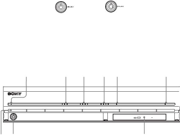
Front
NSR-100/50
1 |
2 |
3 |
4 |
5 |
6 |
POWER |
NETWORK 1 2 3 |
HDD 1 2 3 4 |
STATUS 1 2 3 4 |
ERROR |
REC |
qg qf |
qd |
qs qa 0 9 |
8 |
7 |
A Power LED
Alternates between green and amber lights when the unit is starting up.
Lights green when startup is complete.
Lights amber when it is on standby.
B Network LED (1 to 3)
Lights green when there is activity at the corresponding LAN connector at the rear of the NSR.
C HDD LED
Blinks green when the internal hard disks are accessed.
Lights amber when an error occurs with a hard disk.
D Status LED (1 to 4)
Lights in sequence (1, 2, 3, 4) when the NSR starts.
When an error occurs, the corresponding status LED lights together with the error LED, which lights or blinks to indicate the type of error.
For details, see “STATUS LED” (page 168).
E Error LED
Lights or blinks when an error occurs.
F REC LED
Lights when recording images.
G DVD/CD drive
Use this drive to write data from the NSR hard disks to DVD and CD.
* For details on compatible media, refer to “Notes and Limitations” (page 173).
H USB connector
Use this connector to connect a USB keyboard, mouse, USB flash memory or the RM-NS10 remote control unit to the NSR.
Chapter 1 Introduction |
8 |
|
|
I Audio input connector*
Use this connector to input audio from a peripheral audio device, such as a microphone.
J Audio output connectors (L and R)
Use these connectors to output audio to a peripheral audio device.
K Video output connector
Use this connector to output video to a peripheral video device, such as a VCR.
The displayed images are the same as those for monitor connector 1.
L Monitor connector 1
Use this connector to connect a monitor.
M CompactFlash card slot
Use this slot to save configuration data from the NSR hard disks to a
CompactFlash card.
N Lock
Use this in conjunction with the supplied front panel key to lock the front bezel. When the front bezel is locked, you cannot pull out the front bezel. Also, do not lock the front bezel when the front bezel is pulled out. You can distinguish the locked position from the unlocked position by looking at the lock, as illustrated below.
The front bezel is |
The front bezel is |
locked |
unlocked |
O Vent holes
These openings allow air to flow from the front of the NSR to the rear.
Do not block the vent holes, allow dust to accumulate in the inner mesh of the vent holes, or obstruct the airflow in any way. Obstructing the airflow allows heat to build up inside the NSR and may result in fire or damage.
* This feature is not currently supported.
NSR-25
1 |
2 |
3 |
4 |
5 |
6 |
POWER |
NETWORK 1 2 3 |
HDD 1 2 3 4 |
STATUS 1 2 3 4 |
ERROR |
REC |
9 8 |
7 |
Chapter 1 Introduction |
9 |
|
|

A Power LED
Alternates between green and amber lights when the unit is starting up. Lights green when startup is complete.
Lights amber when it is on standby.
B Network LED
Lights green when there is activity at the corresponding LAN connector at the rear of the NSR.
C HDD LED
Blinks green when the internal hard disks are accessed.
Lights amber when an error occurs with a hard disk.
D Status LED (1 to 4)
Lights in sequence (1, 2, 3, 4) when the NSR starts.
When an error occurs, the corresponding status LED lights together with the error LED, which lights or blinks to indicate the type of error.
For details, see “STATUS LED” (page 168).
E Error LED
Lights or blinks when an error occurs.
F REC LED
Lights when recording images.
G Combo drive
Use this drive to write data from the NSR hard disks to CD.
H Lock
Use this in conjunction with the supplied front panel key to lock the front bezel. When the front bezel is locked, you cannot pull out the front bezel. Also, do not lock the front bezel when the front bezel is pulled out. You can distinguish the locked position from the unlocked position by looking at the lock, as illustrated below.
The front bezel is |
The front bezel is |
locked |
unlocked |
I Vent holes
These openings allow air to flow from the front of the NSR to the rear.
Do not block the vent holes, allow dust to accumulate in the inner mesh of the vent holes, or obstruct the airflow in any way. Obstructing the airflow allows heat to build up inside the NSR and may result in fire or damage.
Chapter 1 Introduction |
10 |
|
|
Rear
NSR-100/50
1 |
2 |
3 |
45 |
|
6 |
|
|
|
|
|
7 |
|
|
8 |
|
|
|
||||||||||||
|
|
|
|
|
|
|
|
|
|
|
|
|
|
|
|
|
|
|
|
|
|
|
|
|
|
|
|
|
|
|
|
|
|
|
|
|
|
|
|
|
|
|
|
|
|
|
|
|
|
|
|
|
|
|
|
|
|
|
|
|
|
|
|
|
|
|
|
|
|
|
|
|
|
|
|
|
|
|
|
|
|
|
|
|
|
|
|
|
|
|
|
|
|
|
|
|
|
|
|
|
|
|
|
|
|
|
|
|
|
|
|
|
|
|
|
|
|
|
|
|
|
|
|
|
|
|
|
|
|
|
|
|
|
|
|
|
|
|
|
|
|
|
|
|
|
|
|
|
|
|
|
|
|
|
|
|
|
|
|
|
|
|
|
|
|
|
|
|
|
|
|
|
|
|
|
|
|
|
|
|
|
|
|
|
|
|
|
|
|
|
|
|
|
|
|
|
|
|
|
|
|
|
|
|
|
|
|
|
|
|
|
|
|
|
|
|
|
|
|
|
|
|
|
|
|
|
|
|
|
|
|
|
|
|
|
|
|
|
|
|
|
|
|
|
|
|
|
|
|
|
|
|
|
|
|
|
|
|
|
|
|
|
|
|
|
|
|
|
|
|
|
|
|
|
|
|
|
|
|
|
|
|
|
|
|
|
|
|
|
|
|
|
|
|
|
|
|
|
|
|
|
|
|
|
|
|
|
|
|
|
|
|
|
|
|
|
|
|
|
|
|
|
|
|
|
|
|
|
|
|
|
|
|
|
|
|
|
|
|
|
|
|
|
|
|
|
|
|
|
|
|
|
|
|
|
|
|
|
|
|
|
|
|
|
|
|
|
|
|
|
|
|
|
|
|
|
|
|
|
|
|
|
|
|
|
|
|
|
|
qf qd qs qa 0 9
A Fan
Take care not to obstruct the fan grille. If the grille is obstructed, heat may build up in the unit, leading to damage and/or fire.
B Power switch
Press the switch in the a position to turn on the unit.
C Video output connector
Use this connector to output video to a peripheral video device, such as a VCR.
The displayed images are the same as those for monitor connector 1.
D S-video output connector
Use this connector to output video to a peripheral video device equipped with an S-video connector.
The displayed images are the same as those for monitor connector 1.
E Serial connector (RS-232C)
Use this connector to connect the control line of the uninterruptible power supply (UPS).
F Sensor input connector
Use this connector to connect the sensor input lines.
For connection details and wiring diagrams for sensor inputs, see the “I/O Port” (page 170).
G Alarm output connector
Use this connector to connect the alarm output lines.
For connection details and a wiring diagram for alarm output, see the “I/O Port” (page 170).
H Audio input connector*
Use this connector to input audio from a peripheral audio device, such as a microphone.
I SCSI connector*
Use this connector to connect a peripheral SCSI device.
Chapter 1 Introduction |
11 |
|
|

J USB connector
Use this connector to connect a USB keyboard, mouse, USB flash memory or the RM-NS10 remote control unit to the NSR.
K LAN connectors (1 to 3)
Use these connectors to connect 10 Base-T, 100 Base-TX, or 1000 Base-T network cables to the NSR.
NIC1: Network cameras NIC2: Remote Clients
NIC3: External storage devices**
L Monitor connectors (1 and 2)
Use these connectors to connect a monitor.
M Audio output connectors (L and R)
Use these connectors to output audio to a peripheral audio device.
N Power supply connector
Use this connector to connect the power cord.
*This feature is not currently supported.
**External storage devices may not be supported depending on the software version. For details, consult your dealer.
NSR-25
1 |
2 |
3 |
4 |
|
5 |
|
6 |
|
|
|
||||||||||
|
|
|
|
|
|
|
|
|
|
|
|
|
|
|
|
|
|
|
|
|
|
|
|
|
|
|
|
|
|
|
|
|
|
|
|
|
|
|
|
|
|
|
|
|
|
|
|
|
|
|
|
|
|
|
|
|
|
|
|
|
|
|
|
|
|
|
|
|
|
|
|
|
|
|
|
|
|
|
|
|
|
|
|
|
|
|
|
|
|
|
|
|
|
|
|
|
|
|
|
|
|
|
|
|
|
|
|
|
|
|
|
|
|
|
|
|
|
|
|
|
|
|
|
|
|
|
|
|
|
|
|
|
|
|
|
|
|
|
|
|
|
|
|
|
|
|
|
|
|
|
|
|
|
|
|
|
|
|
|
|
|
|
|
|
|
|
|
|
|
|
|
|
|
|
|
|
|
|
|
|
|
|
|
|
|
|
|
|
|
|
|
|
|
|
|
|
|
|
|
|
|
|
|
|
|
|
|
|
|
|
|
|
|
|
|
|
|
|
|
|
|
|
|
|
|
|
|
|
|
|
|
|
|
|
|
|
|
|
|
|
|
|
|
|
|
|
|
|
|
|
|
|
|
|
|
|
|
|
|
|
|
|
|
|
|
|
|
|
|
|
|
|
qa 0 9 8 7
A Fan
Take care not to obstruct the fan grille. If the grille is obstructed, heat may build up in the unit, leading to damage and/or fire.
B Power switch
Press the switch in the a position to turn on the unit.
C Serial connector (RS-232C)
Use this connector to connect the control line of the uninterruptible power supply (UPS).
D Sensor input connector
Use this connector to connect the sensor input lines.
For connection details and wiring diagrams for sensor inputs, see the “I/O Port” (page 170).
Chapter 1 Introduction |
12 |
|
|
E Alarm output connector
Use this connector to connect the alarm output lines.
For connection details and a wiring diagram for alarm output, see the “I/O Port” (page 170).
F Audio input connector*
Use this connector to input audio from a peripheral audio device, such as a microphone.
G USB connector
Use this connector to connect a USB keyboard, mouse, USB flash memory or the RM-NS10 remote control unit to the NSR.
H LAN connectors
Use these connectors to connect 10 Base-T, 100 Base-TX, or 1000 Base-T network cables to the NSR.
I Monitor connectors (1 and 2)
Use these connectors to connect a monitor.
J Audio output connectors (L and R)
Use these connectors to output audio to a peripheral audio device.
K Power supply connector
Use this connector to connect the power cord.
* This feature is not currently supported.
Chapter 1 Introduction |
13 |
|
|

System Requirements
The hardware required in order to use this recorder are as follows.
•Sony network cameras
Contact your dealer for details about compatible Sony network cameras.
•Monitor1)
•USB keyboard2)
•USB mouse3)
•Network switch
•1000Base-T/100Base-TX/10Base-T cable
•CF (CompactFlash) card or USB memory device4)
1)For details about monitors supported by the NSR, contact your retailer. The following “Generic” type monitors can be selected.
Frequency is indicated at the end of each line.
-Generic LCD Display; LCD Panel 1024×768; 40-70
-Generic LCD Display; LCD Panel 1280×1024; 50-75
-Generic LCD Display; LCD Panel 1600×1200; 60
-Generic CRT Display; Monitor 1024×768; 50-70
-Generic CRT Display; Monitor 1280×1024; 50-90
-Generic CRT Display; Monitor 1600×1200; 50-90
The following resolutions can be specified.
-XGA (1024×768)
-SXGA (1280×1024)
-UXGA (1600×1200)
2)Use a USB keyboard with a cable. However, keys other than the standard may not function. Wireless or infrared USB keyboards may also not function properly.
3)Use a USB mouse with a cable. However, three-button or wheel mice may not function properly. Wireless or infrared USB mice may also not function properly.
4)Required when backing up system information such as logs.
-For CF, use a card that has been formatted in advance with VFAT.
-For USB memory, use a device that supports general USB Mass Storage Class specifications.
-CF cards are not compatible with the NSR-25.
Chapter 1 Introduction |
14 |
|
|

Initial Configuring the |
Chapter 2 |
System |
Overview
When you first start the NSR, the system configuration window automatically appears. Refer to the section below and configure the necessary settings.
Configuration Flow
Initial configuration |
Modification |
Turn on the NSR.
The system configuration window automatically appears.
See “System Configuration”
System Wizard (page 16).
See below for additional settings
The NSR restarts automatically.
Logon screen
For further configuration
See below for additional settings
Monitoring windw |
|
Modify the system settings. (page 25) |
|
Chapter 2 Initial Configuring the System |
15 |
|
|

Initial configuration settings
•Language
•EULA
•Keyboard Layout
•Time Zone
•Day and Time
•Network Device
•Monitor Model
•Video Settings (only the NSR-100/50)
•Host Name
Additional settings
•NTP
•SNMP
•UPS
Note
You can also modify the settings that you configured during the initial configuration. For details, see “Modifying the System Configuration” (page 25).
System Configuration (First Time: Basic Initial Setup)
When the NSR starts for the first time, you must perform the following procedure.
Caution
The remainder of this manual uses illustrations and screens of the NSR-100/50.
Basic Configuration
1 Connect the USB keyboard and USB mouse to the unit, and turn on the power.
The following screen appears, and a progress bar for hardware startup appears.
Chapter 2 Initial Configuring the System |
16 |
|
|

Then the following screen appears, and a progress bar for software startup appears.
The unit starts and the system settings screen (Setup Wizard) appears.
2 Click [Next].
The [Select Language] screen appears.
3 Select the desired display language from the list, and then click [Next].
The [EULA] screen appears.
4 Read the user license agreement, click [Accept], and then click [Next].
The [Keyboard Layout] screen appears.
Chapter 2 Initial Configuring the System |
17 |
|
|

5 Select the type of USB keyboard connected to the unit from the list, and then click [Next].
The [Time Zone] screen appears.
6 Select the desired time zone from the list, and then click [Next].
*There is no option for enabling or disabling summer time. If you select a time zone in which time is adjusted for summer time, the time is adjusted for summer time automatically.
The [Date and Time] screen appears.
7 Verify the date and time, and configure the correct date and time if necessary, then click [Next].
The [General Network Setting] screen appears.
Chapter 2 Initial Configuring the System |
18 |
|
|

8 Perform the following steps to configure the network settings.
(1)Enter an IP address for each server in the [General Network Setting] screen, and click [Next].
Primary DNS
Enter the primary DNS (Domain Name Server) IP address.
When there is no primary DNS or one is not necessary, do not enter an IP address.
Secondary DNS
Enter the secondary DNS IP address.
When there is no secondary DNS or one is not necessary, do not enter an IP address.
Default Gateway
Enter the default gateway IP address.
When only the local network is used or connection to other networks is not necessary, do not enter an IP address.
The [Network Device #1] screen appears.
(2)Configure the [Network Device] settings for each of the LAN ports. When using the NSR-100/50, configure the settings for each of the three LAN ports (LAN1, LAN2, and LAN 3).
When using the NSR-25, configure the settings for the single LAN port (LAN1).
Note
When using the NSR-100/50, connect the following devices to each of the LAN ports.
LAN1: Network cameras LAN2: Remote clients
LAN3: External storage devices (This may not be supported depending on the software version. For details, consult your dealer.)
Chapter 2 Initial Configuring the System |
19 |
|
|
When using a DHCP server to configure address settings automatically
Select [DHCP].
When configuring addresses manually
(1)Select [Static].
(2)Enter the following information.
IP Address
Enter the desired IP address.
Caution
•Before you enter the desired IP address, make sure that it is not already otherwise used on the network. Entering an IP address already in use may lead to erratic operation of the unit, but no error messages appear to indicate the fact.
•Because of IP address attribution rules, setting an invalid address such as the ones below is not allowed. Example: 224.0.0.0 to 255.255.255.255
0.0.0.0 127.0.0.1, etc.
Netmask
Enter the subnet mask address.
Note
The default settings for network devices are as follows.
IP Address: 192.168.[0/1/2]*.1
Netmask: 255.255.255.0
*The settings for each of the network devices #1, #2, and #3 (only network device #1 for the NSR-25).
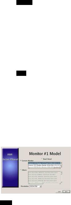
The [Monitor Model] screen appears.
9 Perform screen size settings depending on each monitor port, and then click [Next].
When two monitors are connected, clicking [Dual Head] displays the second monitor configuration screen.
Select the appropriate monitor type and resolution (pixels) for your monitor.
Notes
•The default setting for monitors is as follows.
Generic LCD Display; LCD Panel 1600×1200; 31.5-90; 60 Resolution 1024×768
•Most monitors will operate with [Generic Monitor], but you can select [Others] as required.
Chapter 2 Initial Configuring the System |
20 |
|
|
Caution
When configuring settings for the second monitor, the second monitor must be connected when the NSR restarts.
When using the NSR-100/50, the [Video Setting] screen appears. Proceed to step 10.
When using the NSR-25, the [Host Name] screen appears. Proceed to step 11.
10 Select the appropriate video format, depending on your region, [NTSC] or [PAL], and then click [Next].
* This screen only appears when using the NSR-100/50.
The [Host Name] screen appears.
11 Perform settings for each item, and then click [Next].
Host Name
Enter the host name.
Note
Use only alphanumeric characters, underscores (_), and hyphens (-).
Domain Name
Enter the network domain name according to your network. Example: xxx.sony.co.jp
When you do not register the NSR to the DNS, you do not need to change the default settings.
The [Summary] screen appears.
Chapter 2 Initial Configuring the System |
21 |
|
|

12 Confirm the settings and then click [Next].
The [Warning] screen appears.
13 Click [Finish].
The NSR restarts automatically.
Camera IP Address Configuration and Registration to NSR
After restarting, the logon screen appears.
Next, configure the IP addresses for cameras and register them to the NSR.
1 Enter your user name and password, and then click [Log On].
Default User Name: admin
Default Password: admin
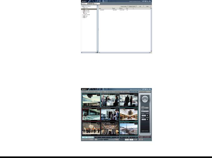
The Camera screen appears in the Configuration window.
Chapter 2 Initial Configuring the System |
22 |
|
|
2
3
Click [Camera IP Setup].
If the IP addresses for the cameras have already been set, click [Register All] and proceed to Step 5.
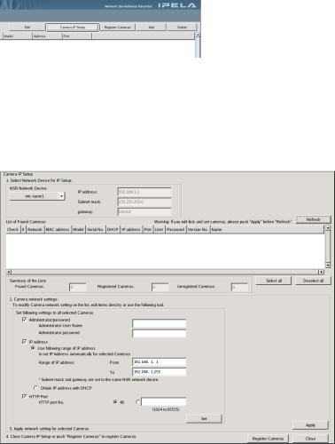
The Camera IP Setup window appears.
Perform the following settings.
In the Camera IP Setup window, you can search for cameras on the same network by MAC address and configure their IP addresses all at once.
(1)Select the network to search in the field labeled “1. Select Network Device for IP Setup.”
Normally, Network 1 is selected as the camera network, and a list of the cameras found appears in the “Found Camera List.” The check boxes of all found cameras are selected.
(2)Enter the following information in the field labeled “2. Set Camera network setting.”
•The user name and password of the camera you are configuring settings for.
•The range of IP addresses on the same network (default: 0 to 254) for which to perform automatic assignment.
•The http port number (default: 80) for communicating with cameras.
*If there is a fixed range of IP addresses that can be assigned to cameras, make sure to specify the correct range.
Chapter 2 Initial Configuring the System |
23 |
|
|
(3)Click [Set].
The information you entered is reflected in the “Found Camera List.” IP addresses are assigned within the specified range. Because the list does not expand to compensate if there are not enough IP addresses, make sure the list is set correctly by directly changing addresses in the list as needed.
At this stage, the settings have not yet been applied to the camera.
(4)Click [Apply].
This configures the camera settings using the information developed in the list.
It takes a few moments for the settings to complete.
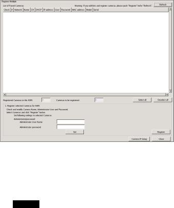
4 When the settings for each camera are complete, click [Register All].
The Register Cameras window appears.
5 Perform the following settings.
In the Register Cameras window, a list of cameras that have not been registered to the NSR appears with the check box for each selected.
(1)Verify the number of cameras selected for registration in the column labeled “Cameras to be registered”, and confirm the user name and password for each camera.
Caution
The user name and password for the cameras are not set by default. You can set the user name and password for the selected cameras simultaneously under “Register selected Cameras for NSR.”
(2)Click [Register].
The selected cameras are registered to the NSR.
*By clicking [Camera IP Setup], you can also return to the previous Camera IP Setup window.
6 When registration is complete, click [Close].
The Configuration window returns to the Camera screen. The registered cameras are listed.
Chapter 2 Initial Configuring the System |
24 |
|
|
7
8
If necessary, configure the individual settings for each camera.
For details about settings, see “Settings” (page 83), Chapter 5.
When you have verified the settings for each camera, click [Monitoring].
The “Monitoring” window appears.
By clicking [Configure], you can switch to the “Configuration” screen and make changes to the settings.
Modifying the System Configuration
1 Click [System] at the top left of the Monitoring window, and then click [Setup Menu] in the [Setup Menu] screen that appears.
The [Setup Menu] screen appears.
Chapter 2 Initial Configuring the System |
25 |
|
|
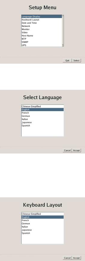
2 Select the [Language Display], and then click [Select].
The [Select Language] screen appears.
3 Select one of the languages displaying in the screen, and then click [Accept].
When you click [Accept], the [Setup Menu] screen returns.
4 Select the [Keyboard Layout], and then click [Select]. The [Keyboard Layout] screen appears.
5 Select the language for the USB keyboard connected to the NSR, and then click [Accept].
When you click [Accept], the [Setup Menu] screen returns.
Chapter 2 Initial Configuring the System |
26 |
|
|

6 Select the [Date and Time], and then click [Select]. The [Date and Time] screen appears.
7
8
Configure the date and time, and then click [Accept].
Year/Month/Day
Enter the date.
Hour/Min
Enter the correct time, and then select [AM] or [PM].
Time Zone
Select the time zone where you are located.
*There is no option for enabling or disabling summer time. If you select a time zone in which time is adjusted for summer time, the time is adjusted for summer time automatically.
When you click [Accept], the [Setup Menu] screen returns.
Select the [Network], and then click [Select].
The [Network Device Menu] screen appears.
9 Select the desired network device, and then click [Select].
The network settings consist of a “General Network Setting” and a “Network Device” that provides LAN ports.
When using the NSR-25, only “Network Device 1” can be set.
Chapter 2 Initial Configuring the System |
27 |
|
|

Note
When using the NSR-100/50, connect the following devices to each of the LAN ports.
LAN 1: Network cameras LAN 2: Remote clients
LAN 3: External storage devices (This may not be supported depending on the software version. For details, consult your dealer.)
10 To configure general settings, click [General Setting] and then [Select].
The [General Network Setting] screen appears.
11 Configure each item below, and then click [Accept].
Primary DNS
Enter the IP address for the primary DNS (Domain Name Server). Skip this entry if a primary DNS is not available or not required.
Secondary DNS
Enter the IP address of the secondary DNS. Skip this entry if a secondary DNS is not available or not required.
Default Gateway
Enter the IP address of the default gateway. Skip this entry when only a local network is used or when connections to other networks are not required.
Hosts Setting
If a host name needs to be registered in the hosts file, enter the IP address and corresponding host name, and then click [Add] to add it to the list.
12 To configure each LAN port, click [Network Device] and then [Select].
Configure the “Network Device” settings for each of the LAN ports. The [Network Device] screen appears.
Chapter 2 Initial Configuring the System |
28 |
|
|

13 Configure each item, and then click [Accept].
Configure the settings depending on your network.
When using a DHCP server to configure address settings automatically
Select [DHCP].
When wanting to configure addresses manually
(1)Select [Static].
(2)Enter the following information.
IP Address
Enter the desired IP address.
Notes
•Before you enter the desired IP address, make sure that it is not already used on the network. Entering an IP address already in use may lead to erratic operation of the unit, but no error messages appear to indicate the fact.
•Because of IP address attribution rules, setting invalid addresses such as the ones below are not allowed.
Example: 224.0.0.0 to 255.255.255.255 0.0.0.0
127.0.0.1, etc.
Netmask
Enter the subnet mask address.
Note
The default settings for network devices are as follows.
IP Address:192.168.[0/1/2]*.1
Netmask: 255.255.255.0
*The settings for each of the network devices #1, #2, and #3 (only network device #1 for the NSR-25).
Chapter 2 Initial Configuring the System |
29 |
|
|
14
15
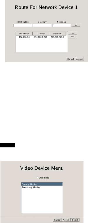
Route Setting
Click if you need to configure a route to another network.
Make the following settings on the [Route For Network Device 1] screen that appears.
(1)Enter the network address, gateway, and net mask, and then click [Add] to add the new network to the list.
For details, consult the network administrator.
(2)Click [Accept].
When you click [Accept], the [Setup Menu] screen returns.
Select the [Monitor], and then click [Select].
The [Video Device Menu] screen appears.
Select the desired monitor, and then click [Select].
When two monitors are connected, the second monitor can be configured if [Dual Head] is clicked.
Caution
When configuring settings for the second monitor, the second monitor must be connected when the NSR restarts.
The [Monitor Model] screen appears.
Chapter 2 Initial Configuring the System |
30 |
|
|
 Loading...