


HCD-GS10
Table of contents
 Loading...
HCD-GS10/GS30DAB
SERVICE MANUAL
Ver. 1.3 2007.05
HCD-GS10/GS30DAB are the Amplifier, CD player
and Tuner section in CMT-GS10/GS30DAB.
Amplifier section
Canadian model:
Continuous RMS power output (reference): 50 + 50 W (6 ohms at
1 kHz, 10% THD)
European and Russian models:
DIN power output (rated): 45 + 45 W (6 ohms at 1 kHz, DIN)
Continuous RMS power output (reference): 50 + 50 W (6 ohms at
1 kHz, 10% THD)
Music power output (reference): 75 + 75 W
Other models:
220 V AC, 50/60 Hz (Argentine model),
127 V AC, 60 Hz (Mexican model)
120 V or 240 V AC, 50/60 Hz (other models)
DIN power output (rated): 45 + 45 W (6 ohms at 1 kHz, DIN)
Continuous RMS power output (reference): 50 + 50 W (6 ohms at
1 kHz, 10% THD)
Inputs
AUDIO IN (stereo mini jack): Sensitivity 775 mV, impedance 22 kilohms
Outputs
PHONES (stereo mini jack): Accepts headphones with an impedance of
8 ohms or more
SPEAKER: Accepts impedance of 6 ohms
CD player section
System: Compact disc and digital audio system
Laser Diode Properties
Emission duration: continuous
Laser Output*: Less than 44.6µW
*This output is the value measurement at a distance of 200mm from the
objective lens surface on the Optical Pick-up Block with 7mm aperture.
Frequency response: 20 Hz – 20 kHz
Signal-to-noise ratio: More than 90 dB
Dynamic range: More than 90 dB
Tuner section
DAB tuner section (UK model):
Frequency range
Band-III: 174.928 (5A) – 239.200 (13F) MHz
* For details, see “DAB frequency table”.
Antenna: FM/DAB lead antenna
Antenna terminal: 75 ohms, F female
Photo : HCD-GS10
SPECIFICATIONS
FM stereo, FM/AM superheterodyne tuner
Antenna:
FM tuner section:
AM tuner section:
DAB frequency table (Band-III)
Frequency Label Frequency Label
174.928 MHz 5A 197.648 MHz 8B
176.640 MHz 5B 199.360 MHz 8C
178.352 MHz 5C 201.072 MHz 8D
180.064 MHz 5D 202.928 MHz 9A
181.936 MHz 6A 204.640 MHz 9B
183.648 MHz 6B 206.352 MHz 9C
185.360 MHz 6C 208.064 MHz 9D
187.072 MHz 6D 209.936 MHz 10A
188.928 MHz 7A 211.648 MHz 10B
190.640 MHz 7B 213.360 MHz 10C
192.352 MHz 7C 215.072 MHz 10D
194.064 MHz 7D 216.928 MHz 11A
195.936 MHz 8A 218.640 MHz 11B
Canadian Model
AEP Model
HCD-GS10
UK Model
HCD-GS30DAB
E Model
HCD-GS10
Model Name Using Similar Mechanism HCD-EC55
Base Unit Name BU-K6BD90-WOD
Optical Pick-up Name KSM-213DCP
FM/DAB lead antenna (UK)
FM lead antenna (Except UK)
AM loop antenna
Tuning range
Canadian model: 87.5 – 108.0 MHz (100 kHz step)
Other models: 87.5 – 108.0 MHz (50 kHz step)
Intermediate frequency: 10.7 MHz
Tuning range
Canadian model: 530 – 1,710 kHz (with 10 kHz tuning interval)
531 – 1,710 kHz (with 9 kHz tuning interval)
European and Russian models: 531 – 1,602 kHz
(with 9 kHz tuning interval)
Other models: 530 – 1,710 kHz (with 10 kHz tuning interval)
531 – 1,602 kHz (with 9 kHz tuning interval)
Intermediate frequency: 450 kHz
(UK model)
Frequency Label
220.352 MHz 11C
222.064 MHz 11D
223.936 MHz 12A
225.648 MHz 12B
227.360 MHz 12C
229.072 MHz 12D
230.784 MHz 13A
232.496 MHz 13B
234.208 MHz 13C
235.776 MHz 13D
237.488 MHz 13E
239.200 MHz 13F
— Continued on next page —
COMPACT DISC DECK RECEIVER
9-887-580-04
2007E16-1
© 2007.05
Sony Corporation
Personal Audio Division
Published by Sony Techno Create Corporation

HCD-GS10/GS30DAB
Ver. 1.3
General
Power requirements:
Canadian model: 120 V AC, 60 Hz
European and Russian models: 230 V AC, 50/60 Hz
Argentine model: 220 V AC, 50/60 Hz
Mexican model: 127 V AC, 60 Hz
Other models: 120 V, 220 V or 230 – 240 V AC, 50/60 Hz,
adjustable with voltage selector
TABLE OF CONTENTS
1. SERVICING NOTES ................................................ 3
2. GENERAL ................................................................... 4
3. DISASSEMBLY
3-1. Disassembly Flow ........................................................... 6
3-2. Side Panel (R) and Side Panel (L) ................................... 7
3-3. Top Panel, DAB Board (UK)........................................... 7
3-4. Front Panel Assy.............................................................. 8
3-5. PANEL Board .................................................................. 8
3-6. HP Board, AUX Board .................................................... 9
3-7. DC Fan ............................................................................ 9
3-8. MAIN Board.................................................................... 10
3-9. REG Board, WIRE HOLD Board ................................... 10
3-10. AC Cord, Tuner (UK)...................................................... 11
3-11. CD Mechanism ................................................................ 11
3-12. AMP Board ...................................................................... 12
3-13. PT Board, Power Transformer......................................... 12
3-14. Belt .................................................................................. 13
3-15. Optical Pick-up (KSM-213DCP), BD90 Board .............. 14
4. TEST MODE ............................................................... 15
5. ELECTRICAL ADJUSTMENTS .......................... 17
6. DIAGRAMS
6-1. Block Diagram — BD/DRIVER Section — .................. 20
6-2. Block Diagram — TUNER Section — .......................... 21
6-3. Block Diagram — MAIN Section —............................. 22
Power consumption:
Canadian model: 100 W
European model: 110 W
Other models: 110 W
Dimensions (w/h/d) (excl. speakers): Approx. 170 × 246 × 307.5 mm
Mass (excl. speakers): Approx. 4.0 kg
Design and specifications are subject to change without notice.
6-4. Printed Wiring Board — BD90 Board — ...................... 23
6-5. Schematic Diagram — BD90 Board — ......................... 24
6-6. Printed Wiring Boards
— MAIN Board , REG Board —.................................... 25
6-7. Schematic Diagram
— MAIN Board (1/2), REG Board — ............................ 26
6-8. Schematic Diagram — MAIN Board (2/2) — ............... 27
6-9. Printed Wiring Board — AMP Board — ....................... 28
6-10. Schematic Diagram — AMP Board — .......................... 29
6-11. Printed Wiring Boards
— PANEL Board , KEY Board (AEP) — ...................... 30
6-12. Schematic Diagram
— PANEL Board , KEY Board (AEP) — ...................... 31
6-13. Printed Wiring Boards
— AUX Board , HP Board — ......................................... 32
6-14. Schematic Diagram
— AUX Board , HP Board — ......................................... 32
6-15. Printed Wiring Board
— PT Board (CND, AEP, UK, RU) — ........................... 33
6-16. Schematic Diagram
— PT Board (CND, AEP, UK, RU) — ........................... 33
7. EXPLODED VIEWS
7-1. Overall Section ................................................................ 40
7-2. Front Panel Section ......................................................... 41
7-3. Chassis Section ................................................................ 42
7-4. CD Mechanism Section................................................... 43
8. ELECTRICAL PARTS LIST .................................. 44
Printed wiring boards, schematic diagrams and electrical parts lists are changed.
See REVISION HISTORY for details of changes on the last page.
Service manual Original SUPPLEMENT-1 SUPPLEMENT-2
Board name suffix suffix suffix
MAIN (REG) board -11, -12 -13
PANEL (KEY) board -11 -12, -13
BD90 board All
DAB board (UK model) -13
Others -11 to -13
PT board
SAFETY-RELATED COMPONENT WARNING!!
COMPONENTS IDENTIFIED BY MARK 0 OR DOTTED LINE
WITH MARK 0 ON THE SCHEMATIC DIAGRAMS AND IN
THE PARTS LIST ARE CRITICAL TO SAFE OPERATION.
REPLACE THESE COMPONENTS WITH SONY PARTS WHOSE
PART NUMBERS APPEAR AS SHOWN IN THIS MANUAL OR
IN SUPPLEMENTS PUBLISHED BY SONY.
CND, AEP, UK, RU AR, E2, E51, SP MX
All suffix Suffix-12, -13 Suffix-13
ATTENTION AU COMPOSANT AYANT RAPPORT
LES COMPOSANTS IDENTIFIÉS P AR UNE MARQUE 0 SUR
LES DIAGRAMMES SCHÉMATIQUES ET LA LISTE DES
PIÈCES SONT CRITIQUES POUR LA SÉCURITÉ DE
FONCTIONNEMENT. NE REMPLACER CES COM- POSANTS
QUE PAR DES PIÈCES SONY DONT LES NUMÉROS SONT
DONNÉS DANS CE MANUEL OU D ANS LES SUPPLÉMENTS
PUBLIÉS PAR SONY.
•Abbreviation
AR : Argentine model
CND : Canadian model
E2 : 120 V AC area in E model
E51 : Chilean and Peruvian models
MX : Mexican model
RU : Russian model
SP : Singapore model
À LA SÉCURITÉ!
2

SECTION 1
When carrying this system
1
Press the ?/1 button to turn the power on.
Insert a disc.
2
Press the CD u button to select CD function.
While pressing the x button, press the Z button for
more 5 seconds.
3
The message “LOCKED” is displayed and the disc slot
is locked. (Even if exiting from this mode, the disc slot
is still locked)
SERVICING NOTES
HCD-GS10/GS30DAB
Ver. 1.3
Notes on chip component replacement
• Never reuse a disconnected chip component.
• Notice that the minus side of a tantalum capacitor may be
damaged by heat.
Flexible Circuit Board Repairing
• Keep the temperature of the soldering iron around 270 °C
during repairing.
• Do not touch the soldering iron on the same conductor of the
circuit board (within 3 times).
• Be careful not to apply force on the conductor when soldering
or unsoldering.
UNLEADED SOLDER
Boards requiring use of unleaded solder are printed with the leadfree mark (LF) indicating the solder contains no lead.
(Caution: Some printed circuit boards may not come printed with
the lead free mark due to their particular size)
: LEAD FREE MARK
Unleaded solder has the following characteristics.
• Unleaded solder melts at a temperature about 40 °C higher
than ordinary solder.
Ordinary soldering irons can be used but the iron tip has to be
applied to the solder joint for a slightly longer time.
Soldering irons using a temperature regulator should be set to
about 350 °C.
Caution: The printed pattern (copper foil) may peel away if
the heated tip is applied for too long, so be careful!
• Strong viscosity
Unleaded solder is more viscou-s (sticky, less prone to flow)
than ordinary solder so use caution not to let solder bridges
occur such as on IC pins, etc.
• Usable with ordinary solder
It is best to use only unleaded solder but unleaded solder may
also be added to ordinary solder.
CAUTION
Use of controls or adjustments or performance of procedures
other than those specified herein may result in hazardous radiation
exposure.
This appliance is classified as a CLASS 1 LASER product.
The CLASS 1 LASER PRODUCT MARKING is located on
the rear exterior.
Laser component in this product is capable of emitting radiation
exceeding the limit for Class 1.
NOTES ON HANDLING THE OPTICAL PICK-UP
BLOCK OR BASE UNIT
The laser diode in the optical pick-up block may suffer electrostatic
break-down because of the potential difference generated by the
charged electrostatic load, etc. on clothing and the human body.
During repair, pay attention to electrostatic break-down and also
use the procedure in the printed matter which is included in the
repair parts.
The flexible board is easily damaged and should be handled with
care.
NOTES ON LASER DIODE EMISSION CHECK
The laser beam on this model is concentrated so as to be focused on
the disc reflective surface by the objective lens in the optical pickup block. Therefore, when checking the laser diode emission,
observe from more than 30 cm away from the objective lens.
CAUTION
MODEL IDENTIFICATION
– Rear Panel –
Parts No.
Model Part No.
GS10 : E2, E51 models 2-319-562-0[]
GS10 : MX model 2-319-563-0[]
GS10 : AR model 2-319-756-0[]
GS10 : SP model 2-319-760-0[]
GS10 : AEP model 2-899-469-0[]
GS10 : RU model 2-899-470-0[]
GS10 : CND model 2-899-471-0[]
GS30DAB : UK model 3-099-988-0[]
• Abbreviation
AR : Argentine model
CND : Canadian model
E2 : 120 V AC area in E model
E51 : Chilean and Peruvian models
MX : Mexican model
RU : Russian model
SP : Singapore model
3

HCD-GS10/GS30DAB
Basic Operations
SECTION 2
GENERAL
This section is extracted
from instruction manual.
Before using the system
To use the remote
Slide and remove the battery compartment lid ȹ, and
insert the two R6 (size AA) batteries (supplied), × side
rst, matching the polarities shown below.
Notes on using the remote
ˎWith normal use, the batteries should last for about six months.
ˎDo not mix an old battery with a new one or mix dierent types of
batteries.
ˎIf you do not use the remote for a long period of time, remove the
batteries to avoid damage from batter y leakage and corrosion.
To set the clock
1
Turn on the system.
Press ÒÄÆ (on/standby)
2
Select the clock set mode.
Press CLOCK/TIMER SET
current mode appears on the display, press Ã/Ñ
ȵ
on the remote repeatedly to select “CLOCK,” and
then press ENTER
3
Set the time.
Press Ã/Ñ
the hour, and then press ENTER
Use t he same procedure to set the minutes.
e clock settings are lost when you disconnect the
power cord or if a power failure occurs.
To display the clock when the system is o, press
Ȭ
DISPLAY
seconds.
ȩ
.
ȷ
on the remote. If the
ȸ
on the remote.
ȵ
on the remote repeatedly to set
ȸ
on the remote.
. e clock is displayed for about 8
Selecting a music source
Press the following buttons (or press FUNCTION Ȯ on
the remote repeatedly).
To select Press
CD
Tun e r
Component (connected using
an audio cord)
Ȯ
CD
on the remote.
TUNER/BAND
Ȯ
AUDI O IN
Ȯ
.
.
Adjusting the sound
To adjust the volume
Press VOLUME +/ˋ on the remote (or turn the
VOLUME control on the unit)
ȱ
.
To add a sound eect
To Pr es s
Generate a more dynamic
sound (Dynamic Sound
Generator X-tra)
Set the sound eect
DSGX
EQ
ȴ
ȴ
on the unit.
.
Playing a CD/MP3 disc
1
Select the CD function.
Press CD on the remote (or FUNCTION on the
remote repeated ly)
2
Place a disc.
Press ì (open/close)
with the label side up on the disc tray.
To c lose the disc tray, press ì (open/close) Ȱ on the
unit.
Do not force the disc tray closed with your nger, as
this may damage the unit.
3
Start playback.
Press à (play) (or CD ā (play/pause) on the unit)
Ȯ
.
To Pr es s
Pause play back
Stop playback
Select a folder on an
MP3 disc
Select a track or le
Find a point in a
track or le
Select Repeat Play
To change the play mode
Press PLAY MODE ȭ repeatedly while
stopped. You can select normal play (“
les in the folder on the disc), shue play (“SHUF” or
SHUF*”), or program play (“PGM”).
“
*When playing a CD-DA disc, (SHUF) Play performs the same
operation as normal (shue) play.
Notes on Repeat Play
ˎAll tracks or les on a disc are played repeatedly up to ve times.
ˎ“REP1” indicates that a single track or le is repeated until you stop
it.
Notes on playing MP3 discs
ˎDo not save other types of tracks or les or unnecessary folders on a
disc that has MP3 les.
ˎFolders that have no MP3 les are skipped.
ˎMP3 les are played back in the order that they are recorded onto
the disc.
ˎe system can only play MP3 les that have a le extension of
“.MP3”.
ˎIf there are les on the disc that have the “.MP3” le extension,
but that are not MP3 les, the unit may produce noise or may
malfunction.
ˎe maximum number of:
ˋfolders is 150 (including the root folder).
ˋMP3 les is 255.
ˋMP3 les and folders that can be contained on a single disc is 256.
ˋfolder levels (the tree structure of les) is eight.
ˎCompatibility with all MP3 encoding/writing soware, recording
device, and recording media cannot be guaranteed. Incompatible
MP3 discs may produce noise or interrupted audio or may not play
at all.
Notes on playing multisession discs
ˎIf the disc begins with a CD-DA (or MP3) session, it is recognized as
a CD-DA (or MP3) disc, and other sessions are not played back.
ˎA disc with a mixed CD format is recognized as a CD-DA (audio)
disc.
Ȯ
.
Ȱ
on the unit, and place a disc
ê (pause) on the remote (or CD
ā on the unit)
play, press the button again.
Ą (stop)
+/ˋȯ.
Ã/Ñ
on the remote (ø/Þ on the
unit)
Hold down ù/ß (rewind/
fast forward)
and release the button at the
desired point.
REPEAT
repeatedly until “REP” or “REP1”
appears.
Ȯ
ȶ
.
(go back/go forward)
ȵ
.
ȵ
during playback,
ȭ
on the remote
the player is
”
for all MP3
. To resume
Listening to the radio
1
Select “FM” or “AM.”
Press TUNER/BAND
2
Select the tuning mode.
Press TUNING MODE
appears.
3
Tune in the desired station.
Press +/ˋ on the remote (or TUNING + or ˋ on the
ȵ
. Scanning stops automatically when a station
unit)
is tuned in, and then “TUNED” and “STEREO” (for
stereo programs only) appear.
To stop automatic scanning
Press Ą (stop) ȶ.
To tune in a station with a weak signal
If “TUNED” does not appear and the scanning does
not stop, press TUNING MODE
“MANUAL” appears and press +/ˋ on the remote (or
TUNING + or ˋ on the unit)
the desired station.
To reduce static noise on a weak FM stereo
station
Press FM MODE ȭ on the remote repeatedly until
“MONO” appears to turn o stereo reception.
Ȯ
repeatedly.
ȭ
repeatedly until “AUTO”
ȭ
repeatedly until
ȵ
repeatedly to tune in
Changing the display
To P ress
Change
information on the
1)
display
Check the clock
when the system
is o
1)
For example, you can view CD/MP3 disc information, such as the
track or le number or folder name during normal play, or the total
playing time while the player is stopped.
2)
e STANDBY indicator Ȫ on the unit lights up when the system is
turned o.
Notes on the display information
ˎe following are not displayed:
ˋtotal playing time for a CD-DA disc depending on the play mode.
ˋtotal playing time for an MP3 disc.
ˋremaining playing time for a track and an MP3 le.
ˎe following are not displayed correctly:
ˋelapsed playing time of an MP3 le encoded using a VBR (variable
bit rate).
ˋfolder and le names that do not follow either the ISO9660
Level 1, Level 2 or Joliet in the expansion format.
ˎe following are displayed:
ˋID3 tag information for MP3 les when ID3 version 1 and version
2 tags are used.
ˋup to 15 characters of ID3 tag information using uppercase letters
(A to Z), numbers (0 to 9), and symbols (‘< > * + , ˋ / @ [ \ ] _).
DISPLAY repeatedly when the
system is on.
when the system is
DISPLAY
2)
. e clock is displayed for 8
o
seconds.
Using optional audio components
To connect an optional headphones
Connect headphones to the PHONES jack ȳ on the
unit.
To connect an optional component
Connect additional audio source components to the
AUDI O IN jack
cord (not supplied). Turn down the volume on the
system, and then select the AUDIO IN function.
Ȳ
on the unit using an analog audio
4
Other Operations
HCD-GS10/GS30DAB
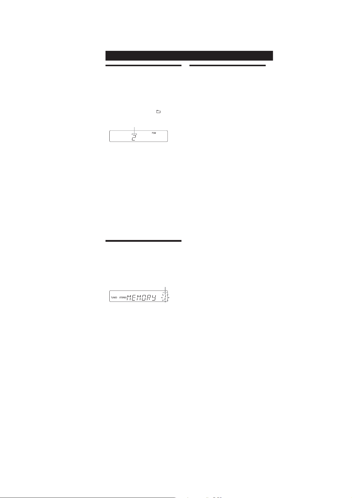
Creating your own CD program
(Program Play)
1
Press CD Ȯ to select the CD function.
2
Press PLAY MODE ȭ repeatedly until “PGM” appears
while the player is stopped.
3
Press Ã/Ñ (or ø/Þ on the unit)
repeatedly until the desired track or le number
appears.
When programing MP3 les, press
repeatedly to select the desired folder, and then select
the desired le.
Selected track or le number
4
Press ENTER ȸ to add the track or le to the
program.
5
Repeat steps 3 through 4 to program additional
tracks or les, up to a total of 15 tracks or les.
6
To play your program of tracks or les, press à (or
CD ā on the unit)
e program remains available until you open the disc
tray. To play the same program again, select the CD
function, and press à (or CD ā on the unit)
To c ancel Program Play
Press PLAY MODE ȭ repeatedly until “PGM”
disappears while the player is stopped.
To delete the last track or le of the program
Press CLEAR Ⱥ on the remote while the player is
stopped.
To view program information, such as total
track number of the program
Press DISPLAY Ȭ repeatedly.
Ȯ
.
+/ˋ
ȵ
ȯ
Ȯ
Presetting radio stations
You can preset your favorite radio stations and tune
them in instantly by selecting the corresponding preset
number.
Use b utton s on the remote to preset stations.
1
Tune in the desired station (See “Listening to the
radio”).
2
Press TUNER MEMORY ȭ.
Preset number
Using the Timers
e system oers two timer functions. If you use both
timers, the Sleep Timer has priority.
Sleep Timer:
You can fall asleep to music. is function works even if
the clock is not set.
Ȼ
Press SLEEP
system automatically turns o aer the current disc stops
or in 100 minutes.
Play Timer:
You c an wake up to CD or tuner at a preset time.
Use b utton s on the remote to control the Play Timer.
Make sure you have set the clock.
1
2
3
4
.
5
6
7
To activate or check the timer again
Press CLOCK/TIMER SELECT ȷ, press Ã/Ñ
repeatedly until “PLAY” appears, and then press ENTER
ȸ
To c ancel the timer
Repeat the same procedure as above until “OFF” appears,
and then press ENTER
To change the setting
Start over from step 1.
Tip
e Play Timer setting remains as long as the setting is not canceled
manually.
repeatedly. If you select “AUTO,” the
Prepare the sound source.
Prepare the sound source, and then press VOLUME
ȱ
to adjust the volume.
+/ˋ
To start from a specic CD track or MP3 le, create
your own CD program.
Press CLOCK/TIMER SET ȷ.
Press Ã/Ñȵ repeatedly to select “PLAY,” and
then press ENTER
“ON TIME” appears, and the hour indication ashes.
Set the time to start playing.
Press Ã/Ñ
then press ENTER
e minute indication ashes. Use the procedure
above to set the minutes.
Use the same procedure as in step 4 to set the time
to stop playing.
Select the sound source.
Press Ã/Ñ
sound source appears, and then press ENTER
display shows the timer settings.
Press ÒÄÆȩ to turn o the system.
If the system is on at the preset time, the Play Timer
will not play.
.
ȸ
.
ȵ
repeatedly to set the hour, and
ȸ
.
ȵ
repeatedly until the desired
ȸ
.
ȸ
. e
ȵ
3
Press +/ˋ (or TUNING + or ˋ on the unit)
repeatedly to select your desired preset number.
If another station is already assigned to the selected
preset number, the station is replaced by the new
stations.
4
Press ENTER ȸ.
5
Repeat steps 1 through 4 to store other stations.
You c an preset up to 20 FM and 10 AM stations. e
preset stations are retained for about half a day even
if you disconnect the power cord or if a power failure
occurs.
6
To call up a preset radio station, press TUNING
ȭ
repeatedly until “PRESET” appears, and
MODE
then press +/ˋ (or TUNING + or ˋ on the unit)
repeatedly to select the desired preset number.
ȵ
ȵ
5

HCD-GS10/GS30DAB
Ver. 1.2
• This set can be disassembled in the order shown below.
3-1. DISASSEMBLY FLOW
SET
3-2. SIDE PANEL (R) AND
SIDE PANEL (L)
(Page 7)
3-3.
TOP PANEL ,
DAB BOARD (UK
(Page 7)
SECTION 3
DISASSEMBLY
)
3-4.
FRONT PANEL ASSY
3-5. PANEL BOARD
(Page 8)
(Page 8)
3-6. HP BOARD,
AUX BOARD
(Page 9)
3-12. AMP BOARD
(Page 12)
3-13. PT BOARD,
POWER TRANSFORMER
(Page 12)
3-7. DC FAN
(Page 9)
3-8. MAIN BOARD
(Page 10)
3-9. REG BOARD,
WIRE HOLD BOARD
(Page 10)
3-10. AC CORD, TUNER (UK
(Page 11)
3-11. CD MECHANISM
(Page 11)
)
3-14. BELT
(Page 13)
3-15. OPTICAL PICK-UP (KSM-213DCP),
BD90 BOARD
(Page 14)
6
s
Note: Follow the disassembly procedure in the numerical order given.
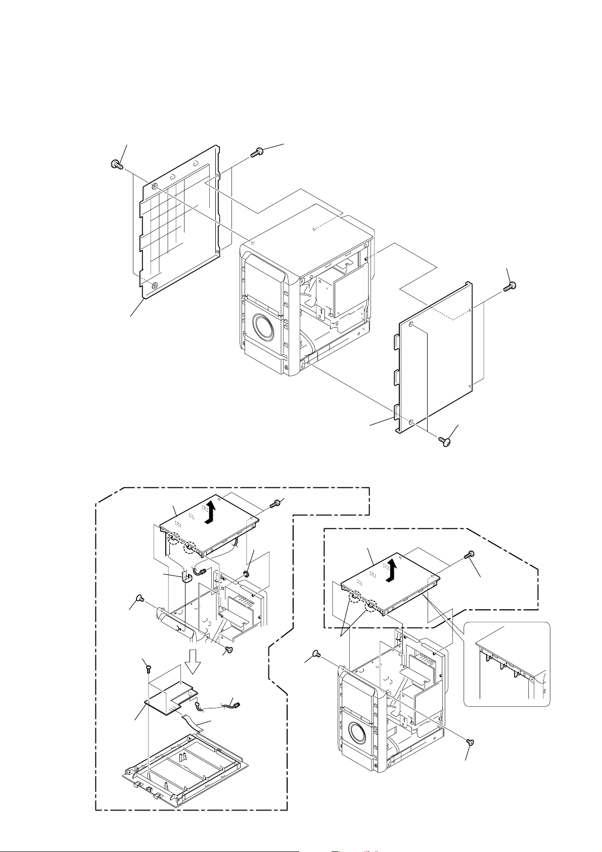
3-2. SIDE PANEL (R) AND SIDE PANEL (L)
4
two screws
(3
×
12)
5
two tapping screws
(+BVTP
3
×
10)
HCD-GS10/GS30DAB
Ver. 1.2
2
two tapping screw
(+BVTP
3
×
10)
6
side panel (L)
3-3. TOP PANEL, DAB BOARD (UK)
(UK)
qa
top panel
0
wire (flat type)
9core (CN500)
7
screw
(+KTP2 3
qs
three screws
(+BVTP 2.6)
×
8
)
6
screw
(+KTP2 3
9
×
8
washer
2
)
3
side panel (R)
8
two tapping screws
(+BVTP
3
×
(EXCEPT UK)
4
two claws
screw
(+KTP2 3
×
8
)
10)
5
top panel
1
two screws
(3
×
12)
3
two tapping screws
(+BVTP
3
×
10)
qg
DAB board
qf
pin connector
qd
wire (flat type)
9core
1
screw
(+KTP2 3
×
8
)
7
HCD-GS10/GS30DAB
Ver. 1.2
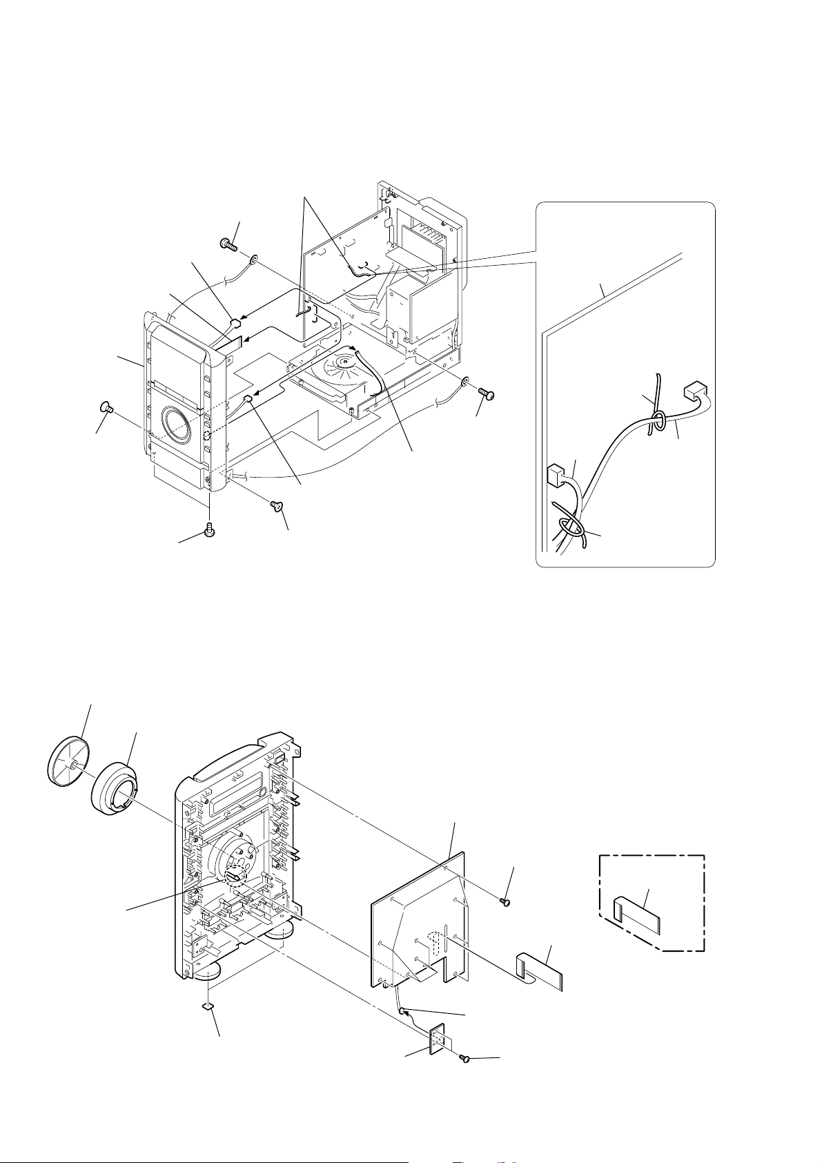
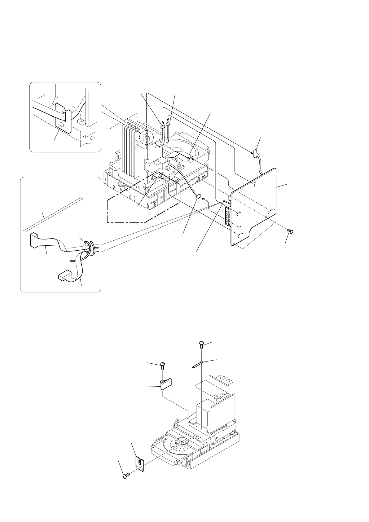
3-4. FRONT PANEL ASSY
2
5
connector
(CN105)
7
wire (flat type)
25core (CN121)
qa
front panel
assy
q;
screw
(+KTP2 3
×
8
)
4
Remove the two harnesses
that is fixed on the clamp.
screw
(+BVTP 3
×
8
)
6
connector
(CN104)
1
3
wire (flat type)
5core (CN601)
screw
(+BVTP 3
PRECAUTION DURING
CONNECTOR INSTALLATION
When assembling,
clamp the two harnesses with
a lead pin.
MAIN board
lead pin
×
8
)
harness
harness
8
two screws
(+BVTP 3
×
3-5. PANEL BOARD
2
knob (VOL)
3
ring (VOL)
8
claw
10
9
screw
)
(+KTP2 3
×
8
)
q;
PANEL board
7
eleven screws
(+BVTP 2.6
×
8
9
wire (flat type)
25core (CN712)
lead pin
(UK)
)
9
wire (flat type)
29core (CN712)
5
connector
1
two foot (felt)
6
KEY board
(CN701)
4
two screws
(+BVTP 2.6
×
8
)
8

)
3-6. HP BOARD, AUX BOARD
)
7
AUX board
6
two dowels
3
HP board
2
JACK HOLD board
1
screw
(+BVTP 2.6
HCD-GS10/GS30DAB
×
8
3-7. DC FAN
3
Remove the harness
that is fixed on the clamp.
5
JACK HOLD board
PRECAUTION DURING CONNECTOR
INSTALLATION
When assembling,
clamp the harness with a lead pin.
4
screw
(+BVTP 2.6
lead pin
MAIN board
4
connector
(CN901)
×
8
)
harness
5
claw
6
back panel
7
DC fan
2
two screws
(+BVTP
1
six tapping screws
(+BVTP
3
×
10)
3
×
14
9
HCD-GS10/GS30DAB
)
Ver. 1.2
3-8. MAIN BOARD
WIRE HOLD board
PRECAUTION DURING
CONNECTOR INSTALLATION
When assembling,
clamp the two harnesses with
a lead pin.
6
connector
(CN202)
5
connector
(CN201)
2
wire (flat type)
21core (CN114)
1
connector
(CN001)
9
MAIN board
MAIN board
lead pin
harness
harness
8
wire (flat type)
11core (CN113)
(UK)
3-9. REG BOARD, WIRE HOLD BOARD
5
screw (+BVTP
6
REG board
7
connector
(CN103)
4
Remove the two harnesses
that is fixed on the clamp.
3
screw (+BVTP
4
3
×
8)
coating clip
3
two screws
(+BVTP
3
×
8
3
×
8)
10
1
screw(+BVTP
2
WIRE HOLD board
3
×
8)
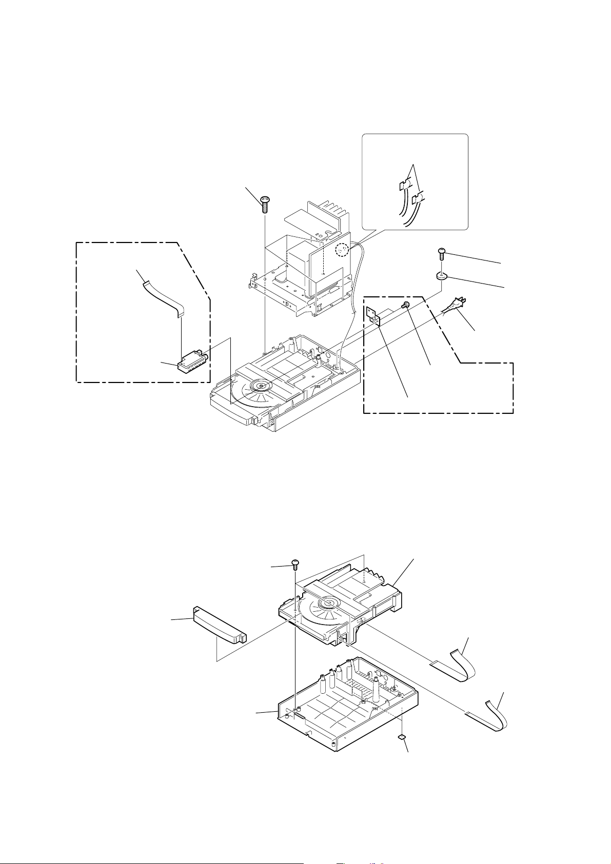
3-10. AC CORD, TUNER (UK)
)
(UK)
8
wire (flat type)
11core
1
five screws
(+BVTP 4
HCD-GS10/GS30DAB
Ver. 1.2
2
Remove soldering from
the two points.
×
12
)
3
screw
(+BVTP 3 × 8)
4
AC HOLD board
9
tuner
3-11. CD MECHANISM
1
door (CD)
3
three screws
(+BVTP
3 × 10
5
AC cord
(UK)
6
two screws
(+BVTT 2.6 × 8)
7
ground plate (tuner)
7
CD mechanism
)
5
wire (flat type)
21core
4
chassis (main)
2
two foot (felt)
6
wire (flat type
5core
11
HCD-GS10/GS30DAB
)
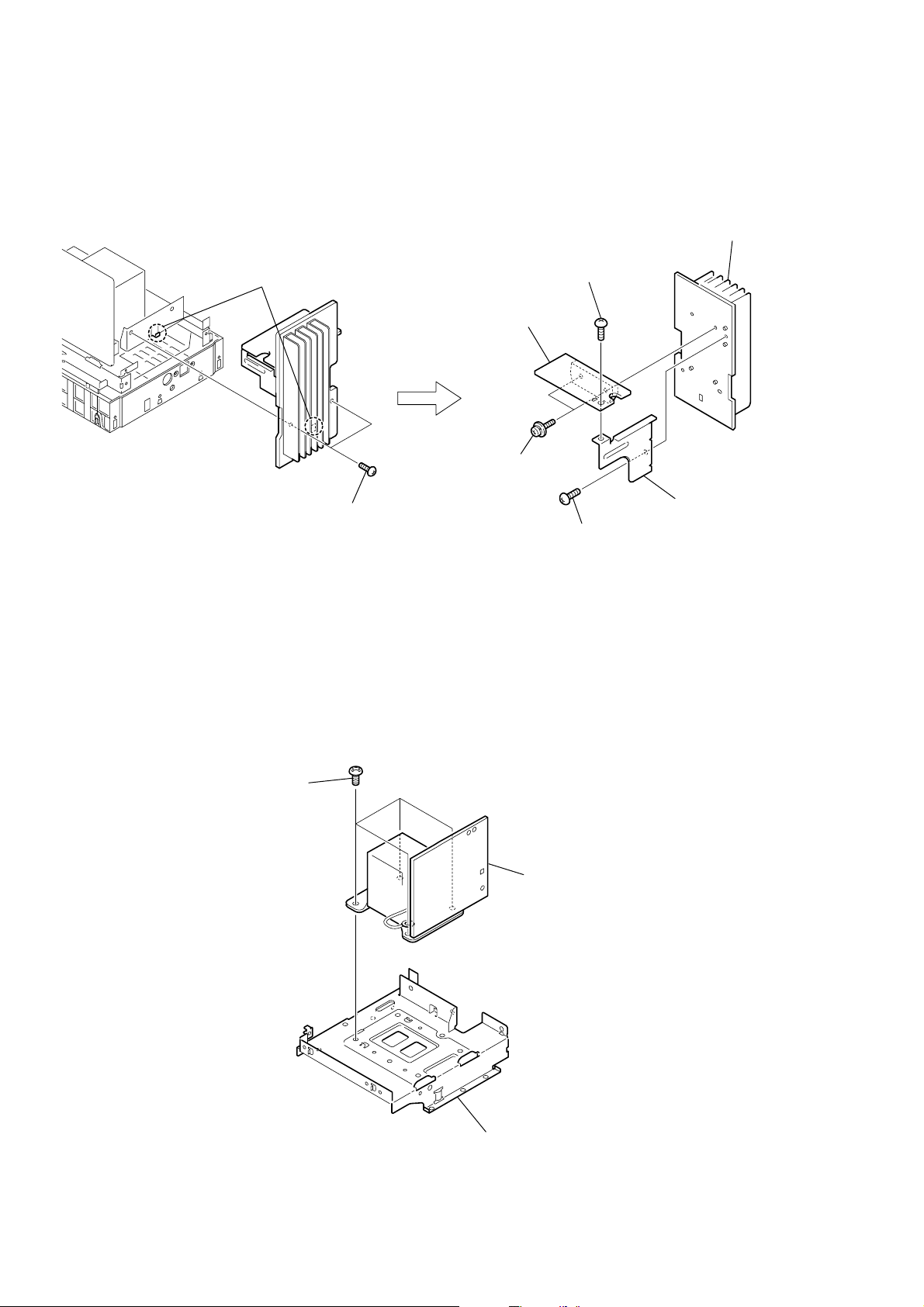
3-12. AMP BOARD
2
claw
8
AMP board
6
two screws
(transistor)
3
screw
(+BVTP
7
heat sink
3
×
8)
1
two screws
(+BVTP
3-13. PT BOARD, POWER TRANSFORMER
1
four screws
(+BVTT 4
× 6
)
5
bracket (heat sink
3
×
10)
4
screw
(+BVTP
3
PT board,
power transformer
3
×
8)
12
2
chassis (PT)
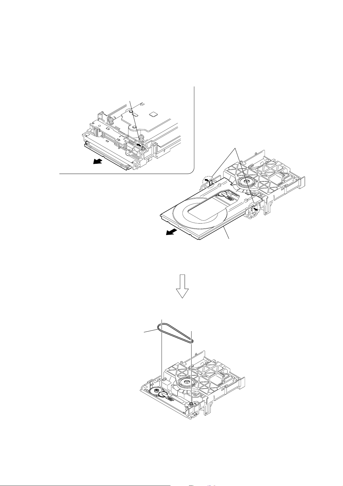
3-14. BELT
1
Move the chuck cam
in the direction of the arrow.
2
bottom side
3
two claws
HCD-GS10/GS30DAB
6
belt
4
5
tray
13
HCD-GS10/GS30DAB
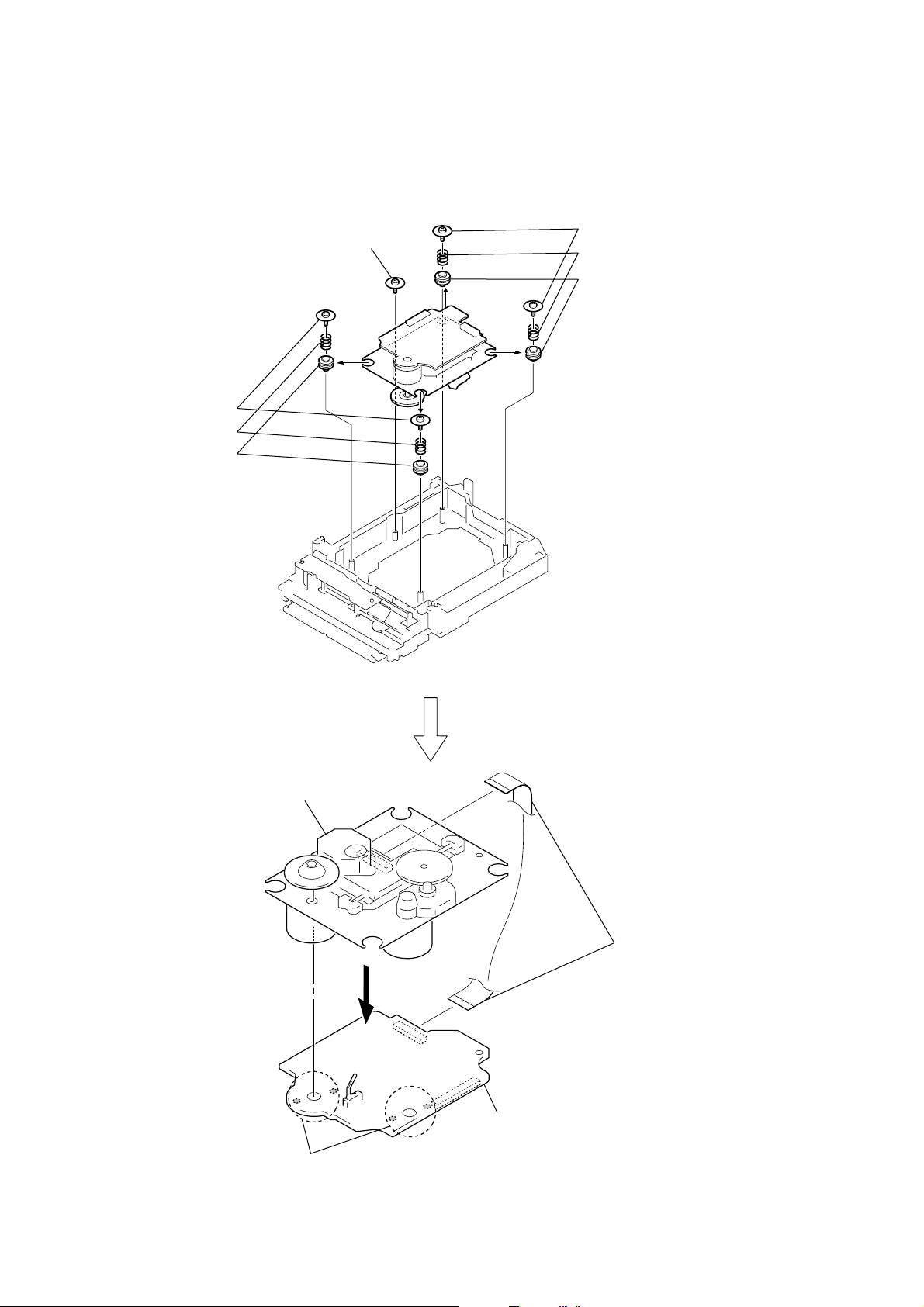
3-15. OPTICAL PICK-UP (KSM-213DCP), BD90 BOARD
7
screw floating
(+PTPWHM 2.6)
4
two floating screws
(+PTPWHM 2.6)
5
two springs (insulator)
6
two insulators
1
two floating screws
(+PTPWHM 2.6)
2
two springs (insulator)
3
two insulators
q;
optical pick-up
(KSM-213DCP)
9
Remove soldering from
the four points.
qa
BD90 board
8
wire (flat type) (16 core)
(CN301)
14

SECTION 4
TEST MODE
HCD-GS10/GS30DAB
Ver. 1.1
[MC COLD RESET]
The cold reset clears all data including preset data stored in the
memory to initial conditions. Execute this mode when returning
the set to the customer.
Procedure:
1. The MC COLD RESET can be executed while the machine is
either in the standby status, or the power-on status.
2. Press three buttons of [DSGX], x , and at last @/1 simulta-
neously.
3. When “RESET” appears, the machine enters standby status.
[PANEL TEST MODE]
Enter The Panel Test Mode
Procedure:
1. In the standby status, press the @/1 button to turn the po wer
on.
2. Press three buttons of [DISPLAY], x , and [DSGX] simulta-
neously.
3. When the panel test mode is activated, LEDs and segments of
LCD are all turned on.
Version Check
Procedure:
1. In the panel test mode (all LEDs and segments of LCD are
turned on), press the [AUDIO IN] button.
2. On the LCD, date and version are displayed “xxxxxxxx”.
For example, “1116V100”.
3. From this status, press the [TUNER/BAND] button, and the
destination is displayed. For example, “GS10CE2”
4. To release from this mode, press three buttons of [DISPLAY],
x , and [DSGX] simultaneously.
[CHANGE-OVER THE AM TUNING INTERVAL]
The AM tuning interval can be changed over 9 kHz or 10 kHz.
Procedure:
1. Press the @/1 button to turn the power on.
2. Press the [TUNER/BAND] button to select TUNER (AM)
function.
3. Press the @/1 button again to turn the power off (standby).
4. After pressing the [DISPLAY] button, while pressing the
TUNING+
5. It turns power on and display “9k STEP” or “10k STEP”, and
thus the tuning interval is changed over.
ML
button, press the @/1 button.
[CD SERVICE MODE]
This mode can move the SLED of the optical pick-up, and also can
turn the optical pick-up laser power on and off.
Procedure:
1. Press the @/1 button to turn the power on.
2.
Press three buttons of x , + , and [DISPLAY] simultaneously.
3. It enters the CD service mode and displays “SERVICE”.
4. To exit from this mode, pr ess three b uttons of x , + and
[DISPLAY]
Key Operation:
TUNING+
simultaneously.
ML
, TUNING–
Use these keys to move the SLED. When
TUNING+
SLED moves to outer circumference and the message
“SLED OUT” is displayed.
When TUNING–
the SLED moves to inner circumference and the
message “SLED IN” is displayed.
ML
ml
is pressed in this mode, the
ml
:
is pressed in this mode,
[CD SLOT LOCK]
This mode is for the antitheft of CD disc in shop. (not for transport)
Procedure:
1. Press the @/1 button to turn the power on.
2. Insert a disc.
3. Press the CD u button to select CD function.
4. While pressing the x button, press the Z button for more 5
seconds.
5. The message “LOCKED” is displayed and the disc slot is
locked. (Even if exiting from this mode, the disc slot is still
locked)
6. If press the Z button to eject the disc, the message
“LOCKED” is displayed and can not eject the disc.
7. To release this lock, while pressing the x button, press the
Z button for 5 seconds again.
8. The message “UNLOCKED” is displayed and the disc slot is
unlocked.
[CD POWER MANAGE]
This mode is for switch the CD power supply on/off. Even if this
state pulls out AC plug, it is held.
Procedure:
1. Press the @/1 button to turn the power on.
2. Insertt a disc.
3. Press the CD u button to select CD function, and press the
x button.
4. Press the @/1 button again to turn the power off (standby).
5. Press the [DISPLAY] button once. While pressing the x button,
press the @/1 button.
6. It turns power on and display “CD POWER”, then display
“ON” or “OFF”.
PLAY MODE/TUNING MODE :
Use this key to turn the optical pick-up laser power
on and off. When the laser power is turned on, the
message “LD ON” is displayed. When the laser
power is turned off, the message “LD OFF” is
displayed.
[CD ERROR CODE]
The past errors of the optical pick-up system (= optical unit + BD
board) are displayed as the BD Errors as shown below.
Procedure:
1. Press the @/1 button to turn the power on.
2. Insert a disc.
3. Press the CD u button to select CD function.
4. Press three buttons of x ,
5. Then, the BD error code is displayed as “D0xxxxxx” (x means
hexadecimal number) on the LCD screen.
6. Every pressing of the TUNING+
increments the number after “D” starting from “D0” up to
“D4”, and then returns to “D0”. Every pressing of the
TUNING–
number after “D”. The smaller the error code number is, the
newer the error content is.
7. To exit from this mode, press the @/1 button to turn the
power off.
ml
[DISPLAY]
button in this mode decrements the
and Z simultaneously.
ML
button in this mode
15

HCD-GS10/GS30DAB
Contents of “BD Errors”
Error display example
D 0 02 09 01
1 234
1 It indicates the error history number
0 to 4: The error history number 0 indicates the newest error.
2 It indicates the error content
01: The focus servo cannot lock-in.
02: GFS is not good (NG).
03: The startup time exceeds the specified period of time (time
over)
04: The focus servo is unlocked continuously.
05: Q code cannot be obtained within the specified period of
time.
06: The tracking servo cannot lock-in.
07: Blank disc
3 It indicates the processing during which the trouble has
occurred.
01: The CD SHIP mode processing is in progress.
02: The POWER OFF processing is in progress.
03: The INITIALIZE processing is in progress.
04: The optical pick-up system (= optical unit + BD board)
is in the stop state.
05: The STOP operation is in progress.
06: The startup processing is in progress.
07: The TOC read-in processing is in progress.
08: The SEARCH operation is in progress.
09: The PLAY operation is in progress.
0A: The PAUSE operation is in progress.
0B: The PLAY – MANUAL SEARCH operation is in
progress.
0C: The PAUSE – MANUAL SEARCH operation is in
progress.
4 It indicates the operation of the processing during which the
trouble has occurred.
It indicates the step number of each processing specified by
3. Because the numbers of steps are different in each
processing, this number can be different in each processing.
16
SECTION 5
AM RF signal
generator
30% amplitude
modulation by
400 Hz signal
Output level: 54 dBuV
60 cm
set
loop antenna A
loop antenna B
+
–
level meter
32
Ω
HP board
PHONES jack (J102)
MAIN board
ANTENNA
CN802 pin
2,3
ELECTRICAL ADJUSTMENTS
HCD-GS10/GS30DAB
Ver. 1.2
CD SECTION
Note:
1. CD Block is basically constructed to operate without adjustment.
2. Use YEDS-18 disc (3-702-101-01) unless otherwise indicated.
3. Use an oscilloscope with more than 10 MΩ impedance.
4. Clean the object lens by an applicator with neutral detergent when the
signal level is low than specified value with the following checks.
5. Check the focus bias check when optical pick-up block is replaced.
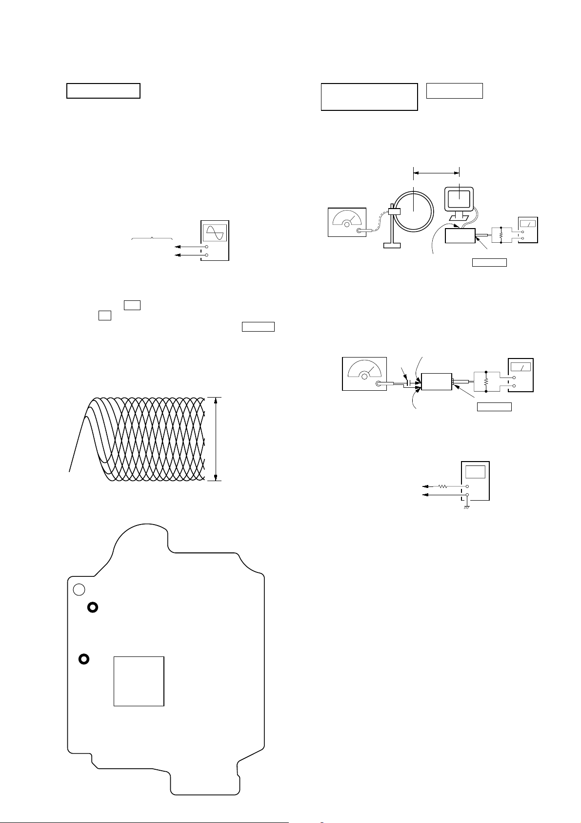
FOCUS BIAS CHECK
oscilloscope
(DC range)
BD90 board
TP (RFI)
TP (VC)
Procedure :
1. Connect oscilloscope to TP (RFI) and TP (VC) on the BD90
board.
2. Press the I/1 button to turn the power ON, and press
the Z (CD) button to open the CD disc tray.
3. Set disc (YEDS-18) on the tray and press the CD u button
to playback.
4. Confirm that oscilloscope waveform is as shown in the f igure
below. (eye pattern)
A good eye pattern means that the diamond shape (◊) in the
center of the waveform can be clearly distinguished.
+
–
VOLT/DIV: 200 mV
TIME/DIV: 500 ns
level:
1.2
±
0.3 Vp-p
TUNER SECTION 0 dB=1 µV
(Except UK)
[AM]
Setting:
FUNCTION: TUNER
TUNER/BAND button: AM
[FM]
Setting:
FUNCTION: TUNER
TUNER/BAND button: FM
FM RF signal
generator
0.01 µF
75kHz frequency
deviation by 1 kHz
signal
Output level: as low as possible
(8dBuV)
MAIN board
ANTENNA
CN802 pin
set
MAIN board
ANTENNA
CN802 pin
digital voltmeter
1
2
level meter
32
Ω
HP board
PHONES jack (J102)
+
–
Checking Location:
– BD90 Board (Side B) –
(VC)
TP
(RFI)
TP
IC101
MAIN board
TP (TUNER–VT)
TP (TUNER–GND)
100 k
Ω
•Repeat the procedures in each adjustment several times.
17
HCD-GS10/GS30DAB
Ver. 1.3
AM FREQUENCY COVERAGE ADJUSTMENT
(Canadian)
Adjustment Part Frequency Display Reading on Digital Voltmeter
Confirmation
AM FREQUENCY COVERAGE ADJUSTMENT
Adjustment Part Frequency Display Reading on Digital Voltmeter
Confirmation
Adjust for a maximum reading on level meter
L851, L803
FM FREQUENCY COVERAGE ADJUSTMENT
Adjustment Part Frequency Display Reading on Digital Voltmeter
L805 87.5 kHz 1.7 ± 0.1 V
Confirmation 108 kHz 6.2 ± 0.5 V
Adjust for a maximum reading on level meter
L804 98 MHz
530 kHz 1.6 ± 0.3 V
1,710 kHz 7.0 ± 0.5 V
(EXCEPT Canadian)
531 kHz 1.6 ± 0.3 V
1,602 kHz 6.7 ± 0.5 V
AM TRACKING ADJUSTMENT
620 kHz (Canadian) /
603 kHz (EXCEPT Canadian)
FM TRACKING ADJUSTMENT
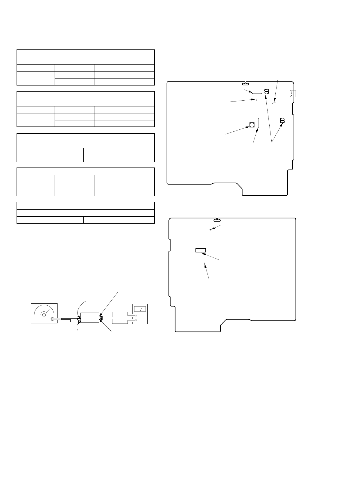
Adjustment Location: MAIN board.
Adjustment Location and Connecting Points
– MAIN BOARD (Component side) –
(TUNER–VT)
FM FREQUENCY
COVERAGE
ADJUSTMENT
FM DETECTOR
ADJUSTMENT
(TUNER–GND)
L851
L805
L806
AM TRACKING
ADJUSTMENT
– MAIN BOARD (Conductor side) –
TP(TUNER–VT)
FM TRACKING
ADJUSTMENT
1
CN802
3
L804
L803
[FM DETECTOR ADJUSTMENT]
Setting:
FUNCTION: TUNER
TUNER/BAND button: FM
FM RF signal
generator
Carrier frequency: 98MHz
Modulation:
deviation by FM 75 kHz
Output level: 60 dBuV
MAIN board
ANTENNA
CN802 pin
set
MAIN board
ANTENNA
CN802 pin
MAIN board
IC801 pin
(TUNER OUT L-ch)
1
MAIN board
TP(TUNER–GND)
2
qs
level meter
+
–
1. Tune the set to 98 MHz.
2. Adjust L806 so that modulation distortion may become the
best in the vicinity of the maximum value where the tuner out
level becomes –15dBuV or more.
IC801 pin
(TUNER OUT L-ch)
TP(TUNER–GND)
qs
18
SECTION 6
DIAGRAMS
HCD-GS10/GS30DAB
Ver. 1.3
THIS NOTE IS COMMON FOR PRINTED WIRING BOARDS AND SCHEMATIC DIAGRAMS.
(In addition to this, the necessary note is printed in each block.)
Note on Schematic Diagram:
• All capacitors are in µF unless otherwise noted. (p: pF)
50 WV or less are not indicated except f or electrolytics and
tantalums.
• All resistors are in Ω and
specified.
• f : internal component.
• 2 : nonflammable resistor.
• 5 : fusible resistor.
• C : panel designation.
Note:
The components identified by mark 0 or dotted line with mark 0 are
critical for safety.
Replace only with part
number specified.
• H : adjustment for repair.
• A : B+ Line.
• B : B– Line.
•Voltages are taken with a VOM (Input impedance 10 MΩ).
Voltage variations may be noted due to normal production
tolerances.
•Waveforms are taken with a oscilloscope.
Voltage variations may be noted due to normal production
tolerances.
– BD90 BOARD –
No mark: CD PLAY
– Other Section –
No mark: FM
• Circled numbers refer to waveforms.
• Signal path.
F : TUNER (FM)
f : TUNER (AM)
J : CD
d : AUX
: AUDIO
•Abbreviation
AR : Argentine model
CND : Canadian model
E2 : 120V AC area in E model
E51 : Chilean and Peruvian models
MX : Mexican model
RU : Russian model
SP : Singapore model
1
4
/
W or less unless otherwise
Note:
Les composants identifiés
par une marque 0 sont critiques pour la sécurité.
Ne les remplacer que par une
piéce portant le numéro
spécifié.
Note on Printed Wiring Boards:
• X : parts extracted from the component side.
• Y : parts extracted from the conductor side.
• f : internal component.
•
• Indication of transistor.
: Pattern from the side which enables seeing.
C
Q
B
E
B
These are omitted.
Q
CE
These are omitted.
• Circuit Boards Location
MAIN board
PANEL board
HP board
AUX board
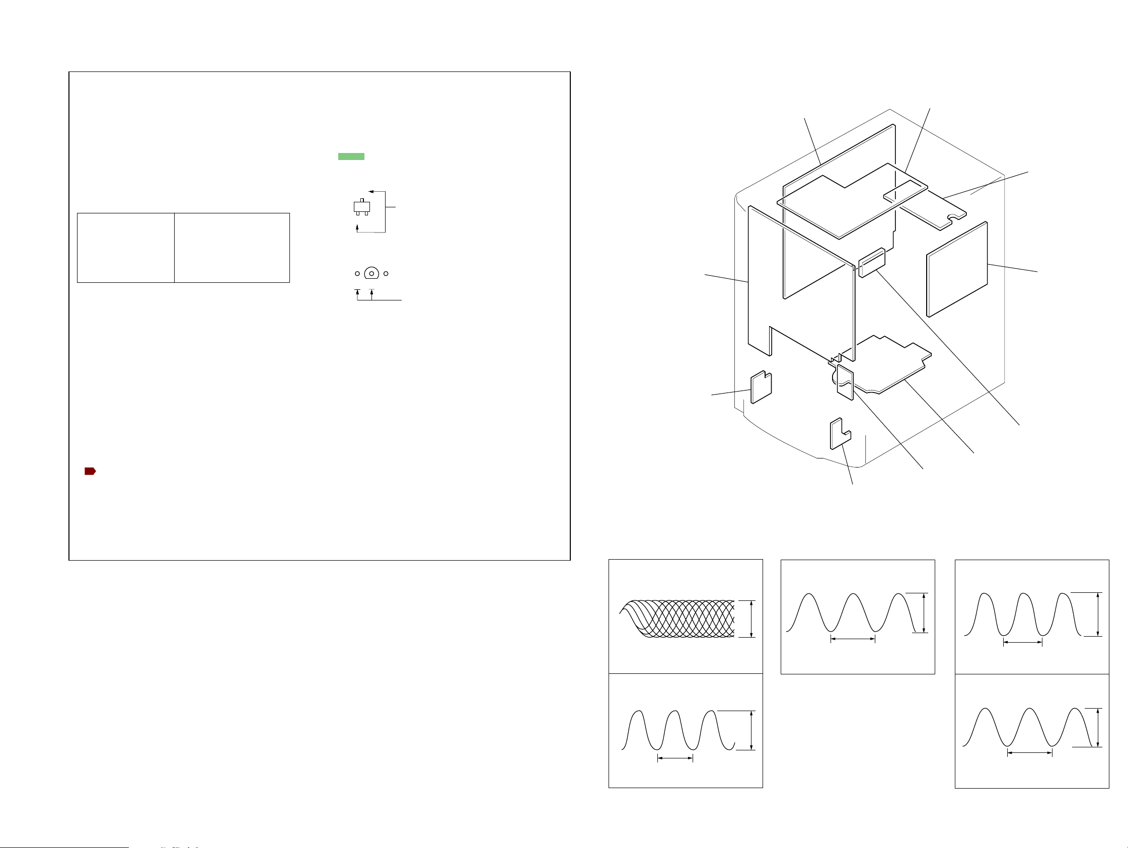
•Waveforms
– BD90 Board – – PANEL Board ––– MAIN Board –
DAB board (UK)
AMP board
PT board
REG board
BD90 board
KEY board
HCD-GS10/GS30DAB
1
IC101 ia (RFI)
(CD PLAY mode)
200 mV/DIV, 500 ns/DIV
2
IC101 wf (XO)
(CD PLAY mode)
59.1 ns
1 V/DIV, 20 ns/DIV
1919
1.3 Vp-p
3.3 Vp-p
1
IC801 w; (XOUT)
13.3 µs
500 mV/DIV, 4
µ
s/DIV
1.5 Vp-p
1
IC701 qd (X0A/P90)
30.5 µs
500 mV/DIV, 10
2
IC701 od (X0)
1 V/DIV, 100 ns/DIV
µ
s/DIV
180 ns
2.2 Vp-p
3.3 Vp-p
HCD-GS10/GS30DAB
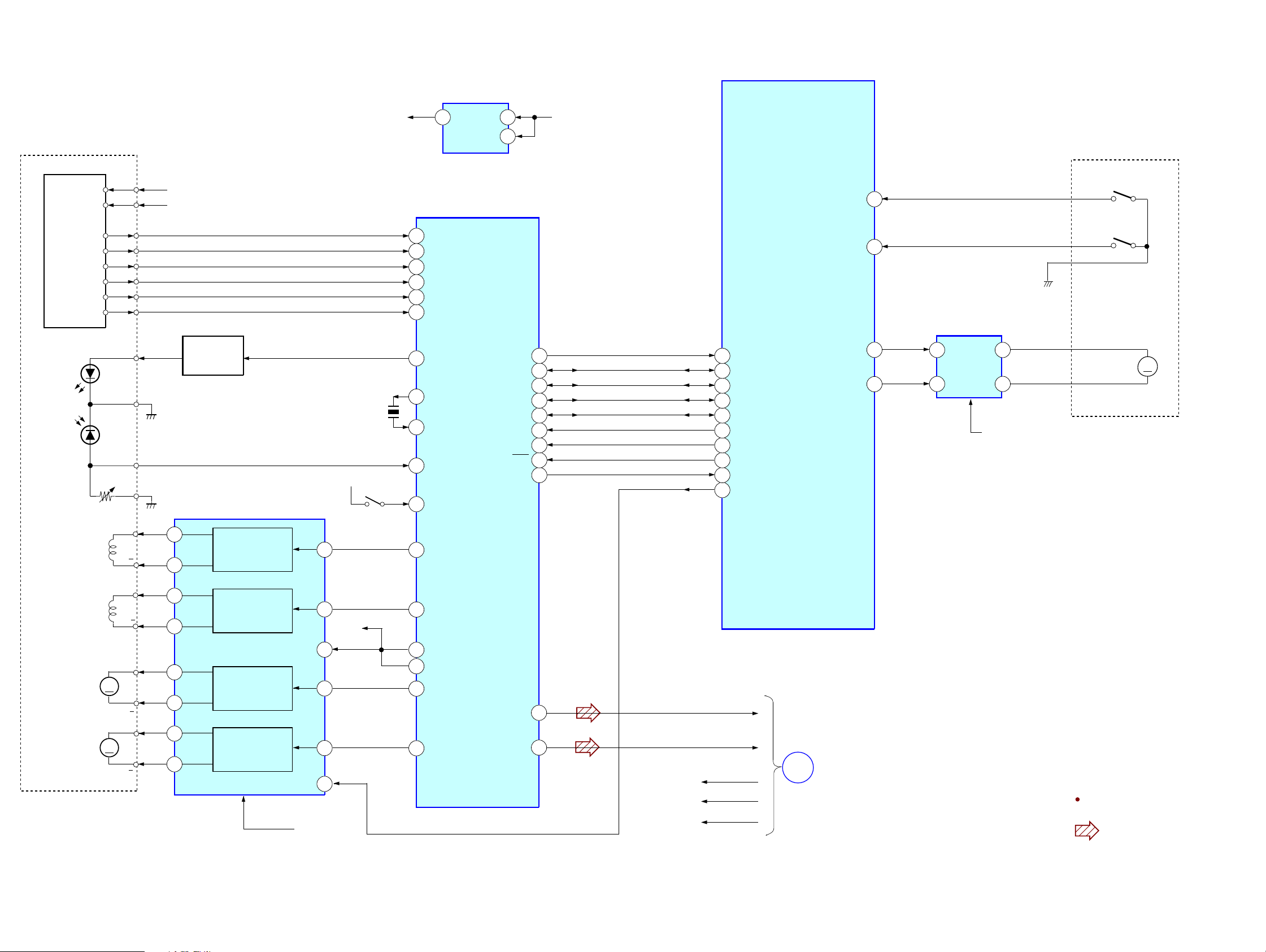
6-1. BLOCK DIAGRAM — BD/DRIVER SECTION —
OPTICAL PICK-UP
BLOCK
(KSM-213DCP)
DETECTOR
VCC
VC
15
16
AVDD (+3.3V)
+1.7V
IC201
5 1
+1.5V
REG
IC101
RF AMP,DSP,MP3
DVDD (3.3V)+1.5V
3
SYSTEM CONTROLLER
IC701
(1/2)
CD MECHANISM DECK
BLOCK
(OPEN)
I-TRYSW-OPEN
11
FOCUS
COIL
LD
PD
12
11
10
13
14
9
Q301
7
8
5
6
F+
4
F
1
AUTOMATIC
CONTROLLER
VO4+
26
VO4-
27
POWER
IC401
SL/SP MOTOR
DRIVER
FOCUS/TRACKING
COIL DRIVER
FOCUS COIL
DRIVE
IN4'
X102
16.934MHz
DVDD (+3.3V)
S201
(LIMIT)
24
95
97
94
96
100
98
91
24
23
92
20
9
FNI 1 (A)
FPI 1 (B)
FNI 2 (C)
FPI 2 (D)
TNI (E)
TPI (F)
LDo
XO
XI
MDI
IO0
FOo
PIO0
BUS0
BUS1
BUS2 (SO)
BUS3 (SI)
BUCK (CLK)
CCE
RST
SBSY
48
38
39
40
41
42
43
37
54
REQ
BUS0
BUS1
BUS2
BUS3
BUCK
CCE
RST
SBSY
M-MUTE
3
5
6
7
8
17
18
19
43
4
I-REQ
IO-BUS0
IO-BUS1
IO-BUS2
IO-BUS3
O-BUCK
O-CCEN
O-XRST
I-SBSY
O-MMUTE
I-TRYSW-CLOSE
O-TRY-OPEN
O-TRY-CLOSE
12
20
21
9
7
IC601
CD
LOADING
MOTOR
DRIVE
2
4
VSTBY
A
B
C
D
E
F
GND
VR
(CLOSE)
OPEN
M
CLOSE
T+
TRACKING
COIL
M401
(SPINDLE)
M402
(SLED)
T
SP+
M
SP
SL+
M
SL
HCD-GS10/GS30DAB
3
2
18
17
12
11
VO3+
TRACKING COIL
VO3-
VO1+
2
VO1-
1
VO2-
DRIVE
SPINDLE
MOTOR
DRIVE
SLED MOTOR
VO2+
DRIVE
IN3'
BIAS
IN1
IN2'
MUTE
20
23
3
9
7
VM (7V)
+1.7V
10
84
11
13
12
TRo
VRo
VREF
DMO
FMO
LO
RO
30
27
L-OUT
R-OUT
DVDD (3.3V)
AVDD (3.3V)
VM (7V)
A
MAIN
SECTION
(Page 22)
Signal Path
: CD
2020
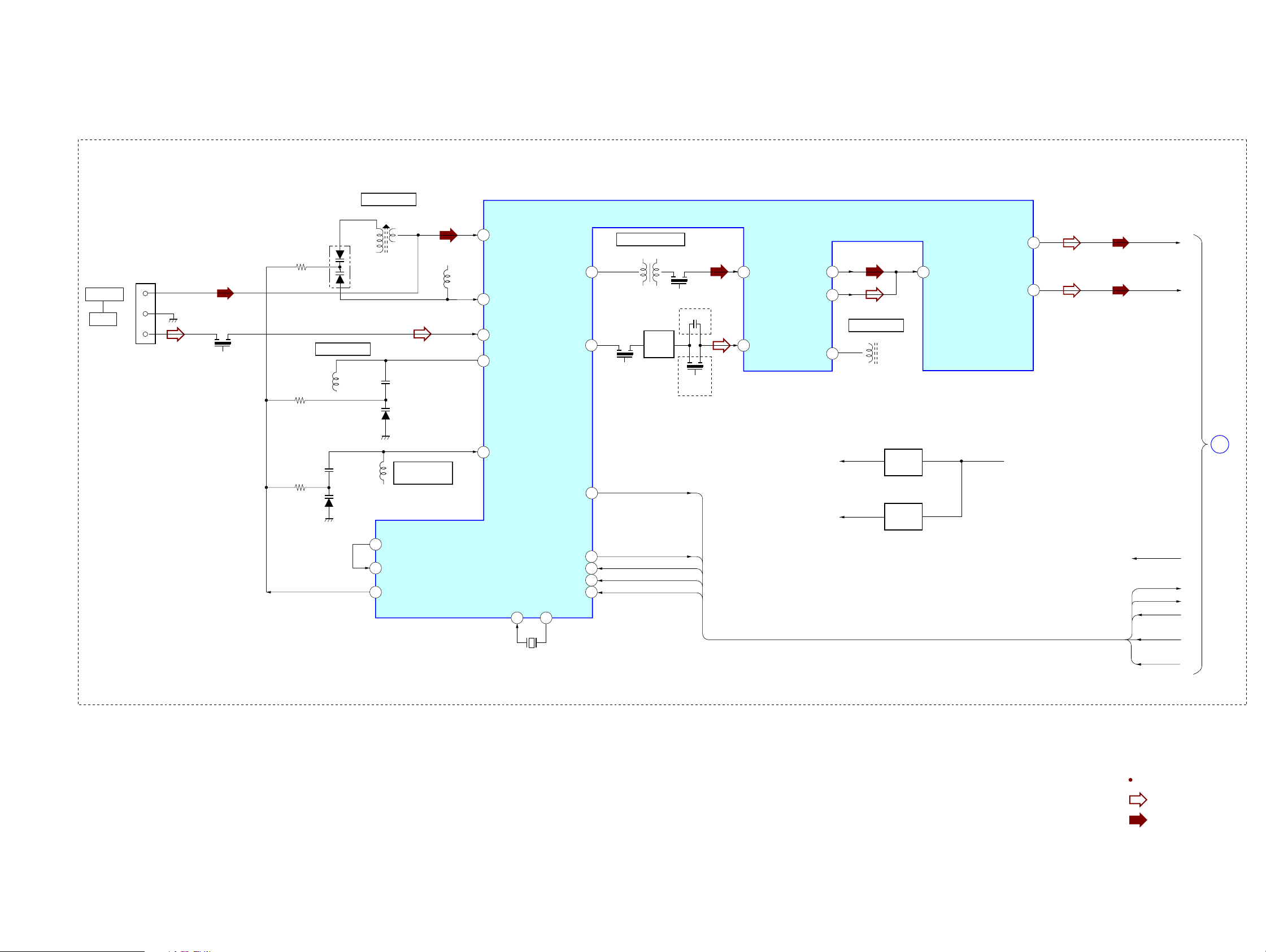
6-2. BLOCK DIAGRAM — TUNER SECTION —
EXCEPT UK
CN802
ANTENNA
FM/AM
3
1
BPF801
FM TRACKING
L804
FM RF
AM TRACKING
D851
L851
D802
L853
1
31
36
34
AM RF-IN
AM-OSC
FM RF-IN
FM RF-OUT
AM-MIX
FM-MIX
5
CF801
10.7MHz
3
IF TRANAFORMER
L803
CF803
450kHz
CND,E2,AR,E51,MX
Q803
FM IF
AMP
C846
CF802
10.7MHz
AEP,RU,SP
IC801
AM/FM IF AMP,
MIX, MPX, DET, OSC
FM/AM PLL
AM IF-IN
7
FM IF-IN
8
AM
DET-OUT
FM
DET-OUT
FM-DET
24
23
11
FM DETECTOR
L806
22
MPX-IN
L-OUT
R-OUT
HCD-GS10/GS30DAB
Ver. 1.3
TUNER
12
13
L-CH
TUNER
R-CH
TU-L
TU-R
D803
L805
FM OSC
PD
26
LP-IN
27
LP-OUT
28
FM FREQUENCY
COVERAGE
32
FM-OSC
XIN
19 20
X801
75kHz
XOUT
AGC
DO
Q801
+3V
REG
25
18
16
DI
17
CL
15
CE
TU-ANSD
TU-DO
TU-DI
TU-CLK
TU-CE
+5V
Q802
+5V
REG
VM9V+3V
VM9V
TU-ANSD
TU-DO
TU-CE
TU-DI
TU-CLK
B
MAIN
SECTION
(Page 22)
HCD-GS10/GS30DAB
Signal Path
: TUNER(FM)
: TUNER(AM)
2121

HCD-GS10/GS30DAB
Ver. 1.3
6-3. BLOCK DIAGRAM — MAIN SECTION —
ANTENNA
MODULE
(DAB
TUNER)
CN301
J105
AUDIO IN
A
BD/DRIVER
SECTION
(Page 20)
AVDD (3.3V)
DVDD (3.3V)
EXCEPT UK
B
TUNER
SECTION
(Page 21)
UK
FM75
COAXIAL
MOD300
R-CH is omitted due to same as L-CH.
Signal Path
AM
TUNER
IC503
BUFFER
6
5
+
+
3
2
: TUNER(FM)
: TUNER(AM)
: CD
: AUX
: AUDIO
R-CH
L-OUT
R-OUT
VM (7V)
TU-L
TU-R R-CH
TU-DO
TU-DI
TU-CLK
TU-CE
TU-ANSD
VM9V VM9V
TU-L
TU-R
TU-DO
TU-DI
TU-CLK
TU-CE
TU-ANSD
RDS-DATA
7
4
R-CH
VM (7V)
AVDD (3.3V)
DVDD (3.3V)
DAB-L
DAB-R
DAB-DZ
DAB-DO
INL4
7
IGOUTL VOLINL
8 9
IGOUTR
10
INL2
5
INB
INL1
4
6
FUNCTION
IC401
UK
R-CH
VOLUME
LOUT
ROUT
DATA
CLK
27
26
22
21
32.768kHz
5.53MHz
SW301
VOLUME
R-CH
X701
X702
RDS-DATA
DAB-DI
DAB-DO
33
34
25
57
56
55
45
14
13
48
40
UK
26
29
31
SYSTEM CONTROLLER
IC701(2/2)
O-VOL-DATA
O-VOL-CLK
I-TU-DO
O-TU-DI
O-TU-CLK
O-TU-CE
I-TU-ANSD
X1A
X0A
93
X0
92
X1
O-POWER_CD
I-RE-VOL-A
I-RE-VOL-B
O-DAB-PWR3.3V
O-DAB-PWR5V
I-RDS-DATA
I-DAB-DI/SIO
I-DAB-DI/SCO
SEG0
SEG31
COM0
COM3
I-KEY1
I-KEY2
I-KEY0
O-LED-STBY
O-LED
I-RMC
I-P-MONI
O-POWER
RSTX
I-HOLD
RY131
Q270, Q271
PROTECT
MONITOR
+VP
-VP
1
Q121,122
POWER
MONITOR
Q102
RELAY
DRIVE
Q131,137
HP
AMP
Q135
RELAY
DRIVE
R-CH
Q901,902
VM9V
D154
D156
D107,108
D109,110
D111,112
RY032(SP,E2,E51)
RY031(AEP,UK,RU,AR,MX)
D001,002
FAN
CONTROL
CURRENT
DET
R-CH
D901
Q903
PT031
POWER
TRANSFORMER
(MAIN)
PT032
POWER
TRANSFORMER
(SUB)
M901
DC FAN
PHONES
L
IMPEDANCE:
R
CND,AEP,UK,RU
J102
J101
SPEAKER
USE 6
AR
SP,E2,E51
S031
VOLTAGE
SELECTOR
230240V
220V
120V
MX
|
|
AC
IN
Q141
HP
MUTE
Q133,134
LEVEL
SHIFT
2O-AMP-ON
LCD702
Q704
RESET
SWITCH
LIQUID CRYSTAL
SW703-708
FUCTION
KEY
SW711-716
FUCTION
KEY
SW701,702
FUCTION
KEY
Q707
LED
DRIVE
DAB+3.3V-ON
DAB+5V-ON
IC703
REMOTE
1
CONTROL
RECEIVER
DISPLAY
LED702
STANDBY
LED701
(BACK LIGHT)
IC701 AVCC
3
g
IC701 VCC
AVDD (3.3V)
DVDD (3.3V)
+3.3V
+5V
D702
TH241
IC501
+3.3V
REG
IC502
+5V
REG
UK
+3.6V
D501
D502
Q241,244
AMP
CONTROL
THERMAL
DET
Q702,703,708
1
Q242
VM (7V)
+3.6V
REG
RESET
3
+9V
IC202
POWER
AMP
5
CD-ON
IC103
+3.3V
REG
Q705,706
7
11
1
D191,192
VM9V
R-CH
Q151-153
PROTECT
DET
CD-ON
SWITCH
CURRENT
DET
Q471,472
+9V
REG
VSTBY
OVERLOAD
PROTECT
Q191,194
Q193
DET
DET
Q201
Q243
D131
R-CH
R-CH
MX
RY131 +B
IC101
+9V
3
REG
63
.
64
.
67
89
.
94
100
59
62
37
38
41
22
46
23
27
28
9
36
1
54
42
HCD-GS10/GS30DAB
2222
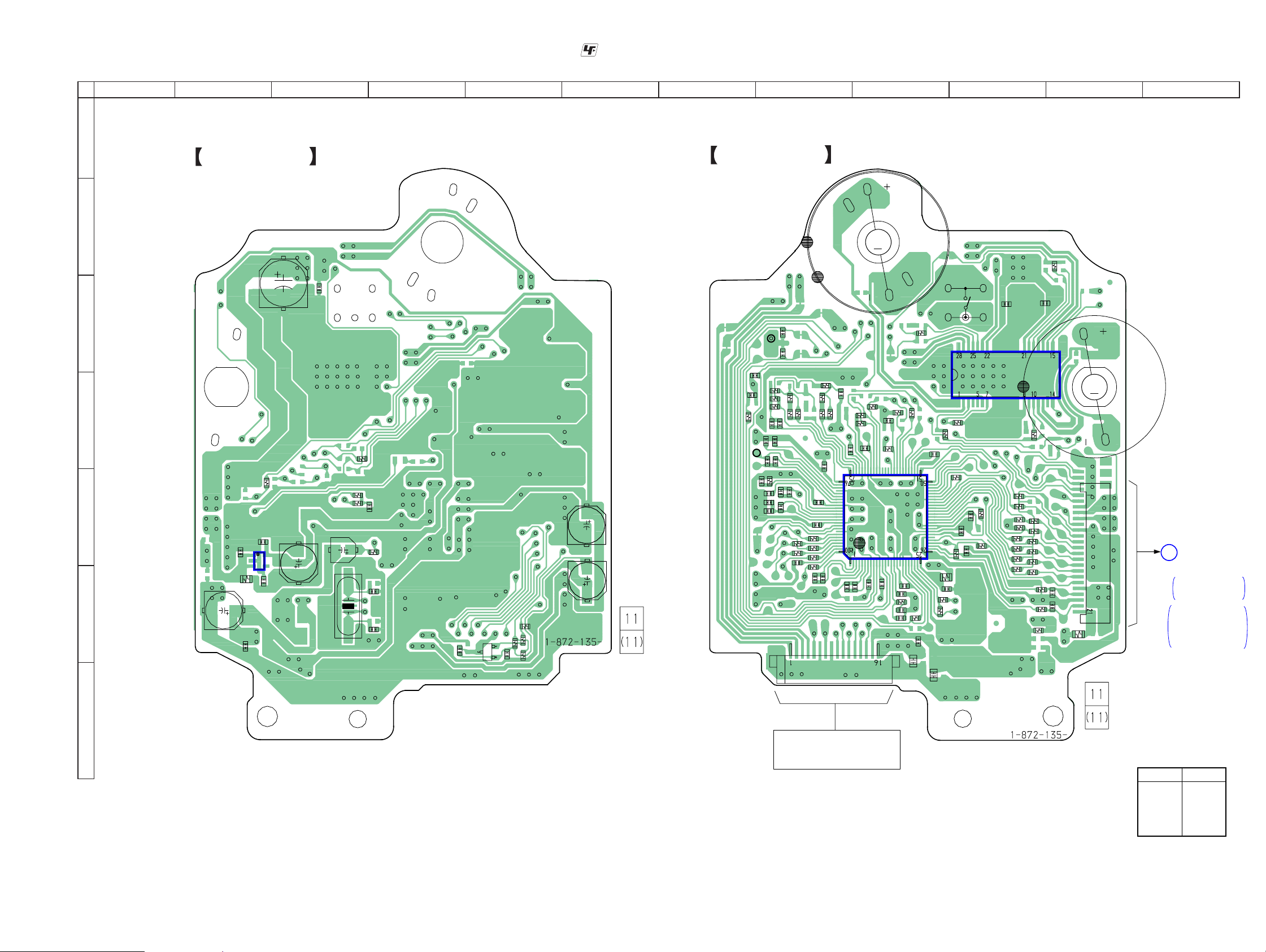
6-4. PRINTED WIRING BOARD — BD90 BOARD —
HCD-GS10/GS30DAB
Ver. 1.1
• See page 19 for Circuit Boards Location. :Uses unleaded solder.
1
2 3 4 5 6 7 8 9 10 11 12
A
BD90 BOARD (SIDE B)
BD90 BOARD (SIDE A)
B
C401
C405
C
D
R212
R211
E
C207
IC201
5
1
C206
3
4
C201
R201
C205
F
C202
C204
X102
C115
R112
R111
C133
R155
C130
C128
C309
Q301
C106
C306
R303
R302
E
C307
R304
R301
TP121
RFI
C123
R151
C122
C144
C148
C149
VC
R143
C143
C140
C141
R140
C138
C124
C139
R144
R148
R142
C137
C142
C146
C150
C125
R136
C147
R135
C145
R146
M
R139
C136
R127
R129
C100
R128
R126
R125
C112
C107
R134
R130
B8
C105
IC101
C104
R145
R147
R149
C118
R150
C117
CN301
C120
C119
C101
M401
(SPINDLE)
C403
R405
M402
(SLED)
B7
R402
S201
(LIMIT)
C404
IC401
M
R118
C153
R114
C102
C113
C103
R101
C126
C127
C303
R120
R102
C108
C301
C302
R104
R106
R105
R415
R414
R113
R154
C132
C109
C116
C110
R153
R210
R209
R218
R219
R220
R221
R222
R223
R408
R157
R156
R108
R208
R207
R206
R205
R204
R203
MAIN BOARD
CN201
A
CN114
SUFFIX-11,12
C151
C152
R202
Page 25
SUFFIX-13
SUPPLEMENT-1
Page 3
R110
B9
G
HCD-GS10/GS30DAB
OPTICAL PICK-UP BLOCK
KSM-213DCP
• Semiconductor
Location
Ref. No.
Location
IC101 E-9
IC201 E-2
IC401 C-10
Q301 F-4
2323

HCD-GS10/GS30DAB
Ver. 1.1
6-5. SCHEMATIC DIAGRAM — BD90 BOARD —
CN301
16P
TP305
OPTICAL
PICK-UP
BLOCK
KSM-213DCP
M401
(SPINDLE)
M
M
M402
(SLED)
TP304
TP301
TP302
TP303
TP306
TP307
TP313
SP-
TP407
SP+
TP408
SL+
F-
T-
F+
TP409
SL-
TP410
T+
TP309
TP310
TP311
TP308
• See page 19 for Waveforms. • See page 34 for IC Block Diagrams. • See page 35 for IC Pin Function Description.
0
C107
C136
0.1
47p
R134
1M
R136 R135
22k 470k
R129
1k
R130
4.7k
0.022
C118
0.01
C117
R142 R139
Q301
2SA2119K
AUTOMATIC POWER
C301
C405
0.1
CONTROLLER
0.1
C303C302
1010
C404
0.1
TP314
IOP1
TP315
IOP2
R303
C306
100
2.2
10V
R304
2.2
C309
0.001
C403
0.1
R301
C307
100k
1
TP312
APC
R302
0
C100
0.1
C106
100 10V
C141
0.0022
C142
0.1
C105
0.1
C143
0.01
0.1
C144
C146
470p
C145
0.01
47p
C148
C104
0.1
R143
C139
C140
0.01
C149
47k
C137
0.01
R144
22k
C150
0.001
R405
10k
R402
2.2k
22k 47k
0.01
TP120
RFI
TP121
TP122
TP124
C147
0.1
TP123
22p
R145
R146
R147
R148
R149
R150
0
R140
0
470p
C138
0
0
0
0
0
R127
0
R126
R125
0
470k
C112 C108
R128
0.1 0.1
R118
100k
C153
R120
0.1
0
1
IC101
RF AMP, DSP, MP3
IC101
TC94A70FG-006
TP105
TP106
TP107
C120
0.01
TP102
TRK
TP101
FCS
0
0.022
TP108
C119
C122
470p
C101
0.1
220
TP109
TP110
R151
0.1
C102
C123
470p
VC
0.0022
0.1
TP111
R101
C127
C126
C103
0.1
C124
0.0047
0.1
C125
0.0047
C113
R102
TP119
R114
10k
TP118
TP117
TP116
TP115
TP114
R113
10k
C133
0.1
R111
100
R110
10k
R112
100
C110
0.1
C109
0.1
R153
1M
R155
47
C116
2
1M
R105
TP113
TP112
16.934MHz
C128
5p
C132
S201
IL-SW
10k
1k
X102
R106
C130
5p
0.1
R104
(LIMIT)
0
0.1
R154
1M
R108
0
TP226
CN201
100
R212
R211
100
R210
100
R209
100
R218
100k
R219
100k
TP224
D1.5V
C207
1
IC201
TK63115SCL-G@GT
C115
22
6.3V
R157
R156
C201
C205
0.1
100
10V
TP225
C202
100
10V
100k
R220
R221
100k
R222
100k
R223
100k
100
C151
470p
100
C152
470p
IC201 IC B/D
+1.5V REG
R201
0
R202
0
C204
0.1
C206
1
R208
100
R207
100
R206
100
R205
100
R204
100
R203
100
TP221
TP222
21P
TP205
TP206
TP207
TP208
TP209
TP210
TP211
TP212
TP213
TP214
TP215
TP216
TP217
TP218
TP219
TP220
TP223
A
MAIN
BOARD(1/2)
CN114
SUFFIX-11,-12
Page 26
SUFFIX-13
SUPPLEMENT-1
Page 4
HCD-GS10/GS30DAB
IC B/D
SP-
SP+
SL+
SL-
FOCUS/TRACKING
COIL DRIVER
IC401
BA5826SFP-E2
R408
R414
4.7k
2.2k
C401
R415
220
47k
10V
SLED
TP103
SPDL
TP104
IC401
SL/SP/MOTOR DRIVER
2424
Loading...