


HCD-EC709iP/EC909iP
SERVICEMANUAL
Ver. 1.0 2010.03
•HCD-EC709iP is the amplifier, CD player, tuner and iPod/iPhone section in MHC-EC709iP.
•HCD-EC909iP is the amplifier, CD player, tuner
and iPod/iPhone section in MHC-EC909iP. |
Photo: HCD-EC909iP |
US Model
Canadian Model
Australian Model
ÎiPod is a trademark of Apple Inc., registered in the U.S. and other countries.
ÎiPhone is a trademark of Apple Inc.
ÎMPEG Layer-3 audio coding technology and patents licensed from Fraunhofer IIS and omson.
ÎAll other trademarks and registered trademarks are of
their respective holders. In this manual, TM and ® marks are not speci ed.
Model Name Using Similar Mechanism |
NEW |
|
|
Base Unit Name |
BU-D1BD73 |
|
|
Optical Pick-up Block Name |
DA11MMVGP |
SPECIFICATIONS
Main unit
AUDIO POWER SPECIFICATIONS
POWER OUTPUT AND TOTAL HARMONIC DISTORTION: ( e United States model only)
Front Speaker
With 12 ohm loads, both channels driven, from 120 – 10,000 Hz; rated 70 watts per channel minimum RMS power, with no more than 0.7% total harmonic distortion from 250 milliwatts to rated output.
Ampli er section
e following measured at AC 120 V, 60 Hz (North American model)
e following measured at AC 240 V, 50/60 Hz (Australian model)
HCD-EC909iP
North American model: Front Speaker
RMS output power (reference):
180 W + 180 W (per channel at 12 , 1 kHz)
Subwoofer
RMS output power (reference): 180 W (at 12 , 80 Hz)
Australian model: Front Speaker Power output (rated):
85 W + 85 W (at 12 , 1 kHz, 1% THD) RMS output power (reference):
180 W + 180 W (per channel at 12 , 1 kHz)
Subwoofer
RMS output power (reference): 180 W (at 12 , 80 Hz)
HCD-EC709iP
North American model:
RMS output power (reference):
180 W + 180 W (per channel at 12 , 1 kHz) Australian model:
Power output (rated):
85 W + 85 W (at 12 , 1 kHz, 1% THD) RMS output power (reference):
180 W + 180 W (per channel at 12 , 1 kHz)
Inputs
PC IN (stereo mini jack): Sensitivity 800 mV, impedance 22 kilohms
Outputs
SPEAKERS: Impedance 12
SUBWOOFER (MHC-EC909iP only): Impedance 12
CD player section
System: Compact disc and digital audio system
Laser Diode Properties
Emission Duration: Continuous
Laser Output*: Less than 44.6µW
*is output is the value measurement at a distance of 200mm from the objective lens surface on the Optical Pick-up Block
with 7mm aperture.
Frequency response: 20 Hz − 20 kHz Signal-to-noise ratio: More than 90 dB Dynamic range: More than 88 dB
Tuner section
FM stereo, FM/AM superheterodyne tuner
Antenna:
FM lead antenna
AM loop antenna
FM tuner section:
Tuning range
North American model: 87.5 MHz − 108.0 MHz (100 kHz step) Australian model: 87.5 MHz − 108.0 MHz (50 kHz step) Intermediate frequency: 225 kHz
AM tuner section:
Tuning range
North American model:
530 kHz − 1,710 kHz (10 kHz step)
531 kHz − 1,710 kHz (9 kHz step) Australian model:
531 kHz − 1,710 kHz (9 kHz step)
530 kHz − 1,710 kHz (10 kHz step) Intermediate frequency: 53 kHz
iPod/iPhone section
Compatible iPod/iPhone models:
iPhone 3GS |
iPhone 3G |
iPhone |
|
iPod nano |
|
iPod classic |
|
5th generation |
iPod touch |
||
120GB |
|||
(video camera) |
2nd generation |
||
160GB (2009) |
|||
|
|
||
iPod nano |
iPod classic |
|
|
4th generation |
iPod touch |
||
160GB (2007) |
|||
(video) |
1st generation |
||
|
|||
iPod nano |
|
|
|
3rd generation |
|
iPod nano |
|
(video) |
iPod classic |
||
2nd generation |
|||
|
80GB |
||
|
(aluminum) |
||
|
|
iPod |
iPod nano |
|
1st generation |
iPod |
|
5th generation |
|
4th generation |
(video) |
|
(color display) |
General
Power requirements:
North American model: AC 120 V, 60 Hz
Australian model: AC 230 V − 240 V, 50/60 Hz
Power consumption:
HCD-EC909iP
North American model: 250 W
Australian model: 250 W
(0.5 W at the Power Saving Mode)
HCD-EC709iP
North American model: 200 W
Australian model: 200 W
(0.5 W at the Power Saving Mode)
Dimensions (W/H/D) (excl. speakers):
Approx. 200 mm × 306 mm × 389 mm
Mass (excl. speakers):
HCD-EC909iP
Approx. 5.7 kg
HCD-EC709iP
Approx. 5.5 kg
Design and speci cations are subject to change without notice.
‡Standby power consumption: 0.5 W
‡Halogenated ame retardants are not used in the certain printed wiring boards.
iPod mini
iPod
4th generation
COMPACTDISCRECEIVER
9-889-760-01 |
Sony Corporation |
2010C05-1 |
Audio&Video Business Group |
© 2010.03 |
Published by Sony Techno Create Corporation |

HCD-EC709iP/EC909iP
NOTES ON CHIP COMPONENT REPLACEMENT
•Never reuse a disconnected chip component.
•Notice that the minus side of a tantalum capacitor may be damaged by heat.
FLEXIBLE CIRCUIT BOARD REPAIRING
•Keep the temperature of soldering iron around 270 °C during repairing.
•Do not touch the soldering iron on the same conductor of the circuit board (within 3 times).
•Be careful not to apply force on the conductor when soldering or unsoldering.
CAUTION
Use of controls or adjustments or performance of procedures other than those specified herein may result in hazardous radiation exposure.
This appliance is classified as a CLASS 1 LASER product. This marking is located on the rear exterior.
SAFETY CHECK-OUT
After correcting the original service problem, perform the following safety check before releasing the set to the customer:
Check the antenna terminals, metal trim, “metallized” knobs, screws, and all other exposed metal parts for AC leakage.
Check leakage as described below.
LEAKAGE TEST
The AC leakage from any exposed metal part to earth ground and from all exposed metal parts to any exposed metal part having a return to chassis, must not exceed 0.5 mA (500 microamperes.). Leakage current can be measured by any one of three methods.
1.A commercial leakage tester, such as the Simpson 229 or RCA WT-540A. Follow the manufacturers’ instructions to use these instruments.
2.A battery-operated AC milliammeter. The Data Precision 245 digital multimeter is suitable for this job.
3.Measuring the voltage drop across a resistor by means of a VOM or battery-operated AC voltmeter. The “limit” indication is 0.75 V, so analog meters must have an accurate low-voltage scale. The Simpson 250 and Sanwa SH-63Trd are examples of a passive VOM that is suitable. Nearly all battery operated digital multimeters that have a 2 V AC range are suitable. (See Fig. A)
To Exposed Metal
Parts on Set
|
|
|
|
|
|
|
|
|
AC |
|
|
|
|
|
|
|
|
|
|
|
|
|
|
|
|
|
|
|
|
0.15 —F |
|
|
|
|
|
1.5 kŸ |
|
|
voltmeter |
|
|
|
|
|
|
|
|
|
(0.75 V) |
|
|
|
|
|
|
|
|
|
|
|
|
|
|
|
|
|
|
|
|
|
|
|
|
|
|
|
|
|
|
|
|
|
|
|
|
|
|
|
|
Earth Ground
Fig. A. Using an AC voltmeter to check AC leakage.
SAFETY-RELATED COMPONENT WARNING!
COMPONENTS IDENTIFIED BY MARK 0 OR DOTTED LINE
WITH MARK 0 ON THE SCHEMATIC DIAGRAMS AND IN
THE PARTS LIST ARE CRITICAL TO SAFE OPERATION.
REPLACE THESE COMPONENTS WITH SONY PARTS
WHOSE PART NUMBERS APPEAR AS SHOWN IN THIS
MANUAL OR IN SUPPLEMENTS PUBLISHED BY SONY.
ATTENTION AU COMPOSANT AYANT RAPPORT
À LA SÉCURITÉ!
LES COMPOSANTS IDENTIFIÉS PAR UNE MARQUE 0 SUR
LES DIAGRAMMES SCHÉMATIQUES ET LA LISTE DES
PIÈCES SONT CRITIQUES POUR LA SÉCURITÉ DE FONC-
TIONNEMENT. NE REMPLACER CES COMPOSANTS QUE
PAR DES PIÈCES SONY DONT LES NUMÉROS SONT DON-
NÉS DANS CE MANUEL OU DANS LES SUPPLÉMENTS
PUBLIÉS PAR SONY.
2
HCD-EC709iP/EC909iP
TABLE OF CONTENTS
1. |
SERVICING NOTES ............................................. |
4 |
5-5. |
Schematic Diagram - BD73 Board -............................... |
19 |
|
|
|
|
5-6. |
Printed Wiring Boards |
|
|
2. |
DISASSEMBLY |
|
|
- iPod & iPhone, JACK Section - ................................... |
20 |
|
2-1. |
Disassembly Flow |
6 |
5-7. |
Schematic Diagram |
|
|
|
|
|
||||
2-2. |
Side Panel (L)/(R) |
6 |
|
- iPod & iPhone, JACK Section - ................................... |
21 |
|
|
|
|
||||
2-3. |
Ornament Plate (Dock) or iPod Assy |
7 |
5-8. |
Printed Wiring Board |
|
|
|
|
|
||||
2-4. |
IP Board Block, Base (Dock) Block |
8 |
|
- MAIN Board (Component Side) - ................................ |
22 |
|
|
|
|
||||
2-5. |
Top Panel Block |
8 |
5-9. |
Printed Wiring Board |
|
|
|
|
|
||||
2-6. |
Back Panel Block |
9 |
|
- MAIN Board (Conductor Side) -.................................. |
23 |
|
|
|
|
||||
2-7. |
MAIN Board |
9 |
5-10. |
Schematic Diagram - MAIN Board (1/2) - ..................... |
24 |
|
|
|
|
||||
2-8. |
Front Panel Block |
10 |
5-11. |
Schematic Diagram - MAIN Board (2/2) - ..................... |
25 |
|
|
|
|
||||
2-9. |
Knob (VOL) |
10 |
5-12. |
Printed Wiring Board - PANEL Board - ......................... |
26 |
|
|
|
|
||||
2-10. |
Base Unit (BU-D1BD73) |
11 |
5-13. |
Schematic Diagram - PANEL Board - ............................ |
27 |
|
|
|
|
||||
2-11. |
Optical Pick-up Block (DA11MMVGP) |
11 |
5-14. |
Printed Wiring Board - POWER Board -........................ |
28 |
|
|
|
|
||||
|
|
|
5-15. |
Schematic Diagram - POWER Board - .......................... |
29 |
|
3. |
TEST MODE ............................................................ |
12 |
6. |
EXPLODED VIEWS |
|
|
|
|
|
|
|||
4. |
ELECTRICAL CHECK ......................................... |
13 |
6-1. |
Overall Section ............................................................... |
34 |
|
|
|
|
6-2. |
Top Panel Section ........................................................... |
35 |
|
5. |
DIAGRAMS |
|
6-3. |
Front Panel Section ......................................................... |
36 |
|
|
6-4. |
iPod Dock Section |
37 |
|||
5-1. |
Block Diagram - CD SERVO, TUNER Section - |
14 |
||||
6-5. |
MAIN Board Section |
38 |
||||
5-2. |
Block Diagram - MAIN Section - |
15 |
||||
6-6. |
Chassis Section |
39 |
||||
5-3. |
Block Diagram |
|
||||
|
|
|
|
|||
|
- PANEL, POWER SUPPLY Section - ........................... |
16 |
7. |
ELECTRICAL PARTS LIST |
40 |
|
5-4. |
Printed Wiring Board - BD73 Board - |
18 |
||||
|
|
|
3
HCD-EC709iP/EC909iP
SECTION 1
SERVICING NOTES
NOTES ON HANDLING THE OPTICAL PICK-UP BLOCK OR BASE UNIT
The laser diode in the optical pick-up block may suffer electrostatic break-down because of the potential difference generated by the charged electrostatic load, etc. on clothing and the human body. During repair, pay attention to electrostatic break-down and also use the procedure in the printed matter which is included in the repair parts.
The flexible board is easily damaged and should be handled with care.
NOTES ON LASER DIODE EMISSION CHECK
The laser beam on this model is concentrated so as to be focused on the disc reflective surface by the objective lens in the optical pickup block. Therefore, when checking the laser diode emission, observe from more than 30 cm away from the objective lens.
UNLEADED SOLDER
Boards requiring use of unleaded solder are printed with the leadfree mark (LF) indicating the solder contains no lead.
(Caution: Some printed circuit boards may not come printed with the lead free mark due to their particular size)
 : LEAD FREE MARK
Unleaded solder has the following characteristics.
•Unleaded solder melts at a temperature about 40 °C higher than ordinary solder.
Ordinary soldering irons can be used but the iron tip has to be applied to the solder joint for a slightly longer time. Soldering irons using a temperature regulator should be set to
about 350 °C.
Caution: The printed pattern (copper foil) may peel away if the heated tip is applied for too long, so be careful!
•Strong viscosity
Unleaded solder is more viscous (sticky, less prone to flow) than ordinary solder so use caution not to let solder bridges occur such as on IC pins, etc.
•Usable with ordinary solder
It is best to use only unleaded solder but unleaded solder may also be added to ordinary solder.
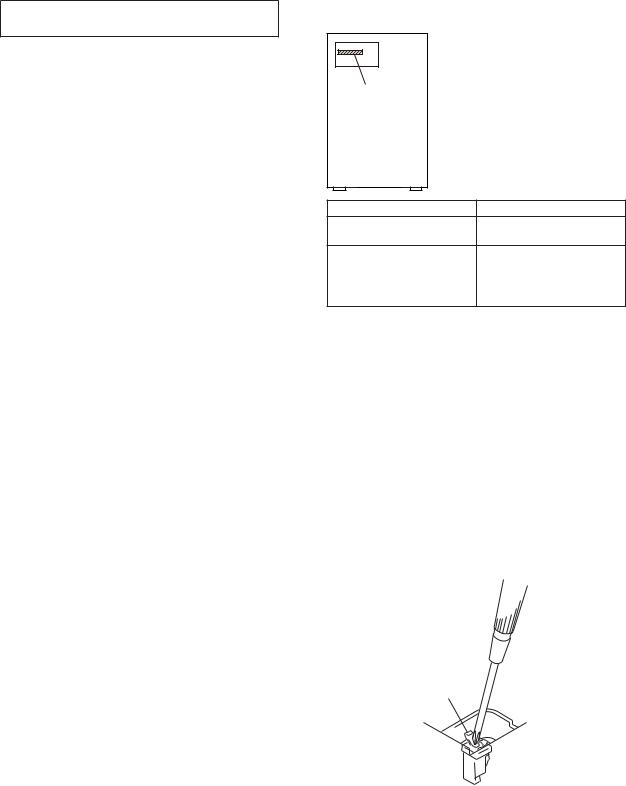
MODEL IDENTIFICATION |
|
- Back Panel - |
|
Power |
|
Voltage |
|
Indication |
|
Model |
Power Voltage Indication |
EC709iP: US and Canadian
120V - 60Hz 200W
models
EC709iP: Australian model |
230–240V - 50/60Hz 200W |
|
|
|
|
EC909iP: US and Canadian |
120V - 60Hz 250W |
|
models |
||
|
||
|
|
|
EC909iP: Australian model |
230–240V - 50/60Hz 250W |
LASER DIODE AND FOCUS SEARCH OPERATION CHECK
During normal operation of the equipment, emission of the laser diode is prohibited unless the upper lid is closed while turning on the S351. (push switch type)
The following checking method for the laser diode is operable.
•Method
Emission of the laser diode is visually checked.
1.Open the upper lid.
2.Push the S351 as shown in Fig. 1.
Note: Do not push the detection lever strongly, or it may be bent or damaged.
3.Check the object lens for confirming normal emission of the laser diode. If not emitting, there is a trouble in the automatic power control circuit or the optical pick-up.
In this operation, the object lens will move up and down 2 times along with inward motion for the focus search.
S351
Fig. 1. Method to push the S351
4
HCD-EC709iP/EC909iP
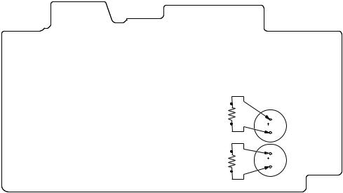
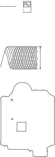
CAPACITOR ELECTRICAL DISCHARGE PROCESSING
When checking the board, the electrical discharge is necessary for the electric shock prevention.
Connect the resistors referring to the figure below.
•POWER board (C103, C104)
Both ends of respective capacitors.
–POWER Board (Conductor Side) –
800 :/2 W
C103
800 |
:/2 W |
C104 |
|
5
HCD-EC709iP/EC909iP
SECTION 2
DISASSEMBLY
•This set can be disassembled in the order shown below.
2-1. DISASSEMBLY FLOW
|
|
|
|
|
|
|
|
|
|
|
|
|
|
|
|
SET |
|
|
|
|
|
|
|
|
|
|
|
|
|
|
|
|
|
|
|
|
|
|
|
|
|
|
|
|
|
|
|
|
|
|
|
|
|
|
|
|
|
|
|
|
|
|
|
||||||
|
|
|
|
|
|
|
|
|
|
|
|
|
|
|
|
|
|
|
|
|
|
|
|
|
|
|
|
2-2. |
SIDE PANEL (L)/(R) |
|
2-3. |
ORNAMENT PLATE (DOCK) OR iPod ASSY |
|
||||||||
|
|
(Page 6) |
|
|
(Page 7) |
|
|
|
|
||||
|
|
|
|
|
|
|
|
|
|
|
|
|
|
|
|
|
|
|
|
|
|
|
|
|
|
|
|
|
|
|
|
|
|
|
|
|
|
|
|
|
|
2-5. |
TOP PANEL BLOCK |
|
2-4. |
IP BOARD BLOCK, BASE (DOCK) BLOCK |
|
||||||||
|
|
(Page 8) |
|
|
(Page 8) |
|
|
|
|
||||
|
|
|
|
|
|
|
|
|
|
|
|||
|
|
|
|
|
|
|
|
|
|
|
|||
|
|
|
|
|
|
|
|
|
|
|
|
|
|
|
|
|
|
|
|
|
|
|
|
|
|
|
|
2-6. |
BACK PANEL BLOCK |
|
2-8. |
FRONT PANEL BLOCK |
|
2-10. |
BASE UNIT (BU-D1BD73) |
||||||
|
|
(Page 9) |
|
|
(Page 10) |
|
|
(Page 11) |
|||||
|
|
|
|
|
|
|
|
|
|
|
|||
|
|
|
|
|
|
|
|
|
|||||
|
|
|
|
|
|
|
|
|
|
|
|
|
|
2-7. |
MAIN BOARD |
|
2-9. |
KNOB (VOL) |
|
2-11. |
OPTICAL PICK-UP BLOCK |
||||||
|
|
(Page 9) |
|
|
(Page 10) |
|
|
(DA11MMVGP) |
|||||
|
|
|
|
|
|
|
|
|
|
|
|
(Page 11) |
|
|
|
|
|
|
|
|
|
|
|
|
|
||
|
|
|
|
|
|
|
|
|
|
|
|
|
|
Note: Follow the disassembly procedure in the numerical order given.
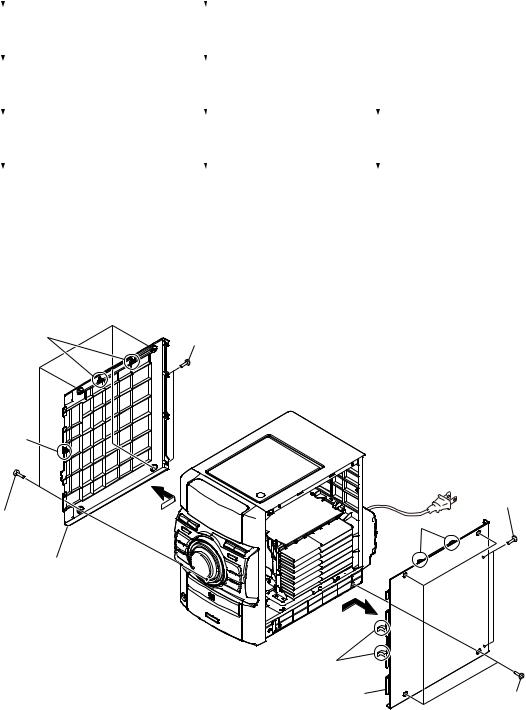
2-2. SIDE PANEL (L)/(R)
3 two claws |
2 two screws |
|
|
|
(BVTP3 u 10) |
3 claw |
|
|
|
4 |
2 two screws |
|
|
|
1 four screws |
|
(BVTP3 u 10) |
(case 3) |
|
3 two claws |
|
|
|
|
5 side panel (L) |
|
4
3 two claws |
|
5 side panel (R) |
1 four screws |
|
|
|
(case 3) |
6
HCD-EC709iP/EC909iP
2-3. ORNAMENT PLATE (DOCK) OR iPod ASSY
2 Push in flat-head screwdriver.
Note 1: Avoid a claw and put a flat-head screwdriver in.
3 claw
1 Open the iPod dock. 


3 claw
4Confirm four claws has come off after shutting the iPod dock.
Note 2: Push the gap by the flat-head screwdriver  when not coming off.
– Bottom view –
7 ornament plate (dock) or iPod assy
6 three claws
5 Turn up a ornament plate (dock) or
iPod assy low part and remove it without using by the flat-head screwdriver.
– Bottom view –
2Push in flat-head screwdriver.
Note 1: Avoid a claw and put a
flat-head screwdriver in.
7

HCD-EC709iP/EC909iP
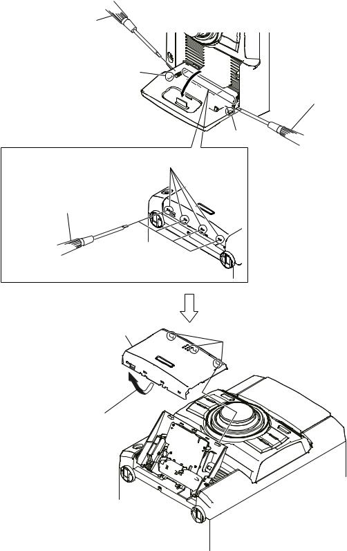
2-4. IP BOARD BLOCK, BASE (DOCK) BLOCK
Note 1: This illustration sees the front panel from bottom side.
6 IP board block
4flexible flat cable
 (13 core) (CN901)

0 boss
2 sheet
9
2 sheet
1 four screws (B2.6)
5 Remove two solders.


 2 sheet
3

qa base (dock) block
8 boss
7
–)URQW SDQHO EORFN LQVLGH YLHZ–
‡$UUDQJHPHQW RI OHDG ZLUH
Never put the sheet to the claw.
red black
sheet
sheet sheet
Note 2: The hole of the front panel that passes the flexible flat cable (13 core) and the wire from the IP board block is different.
Please pass it through a correct hole respectively. There is a possibility that trouble occurs when iPod dock is opened or closed when it makes a mistake in the passed hole.
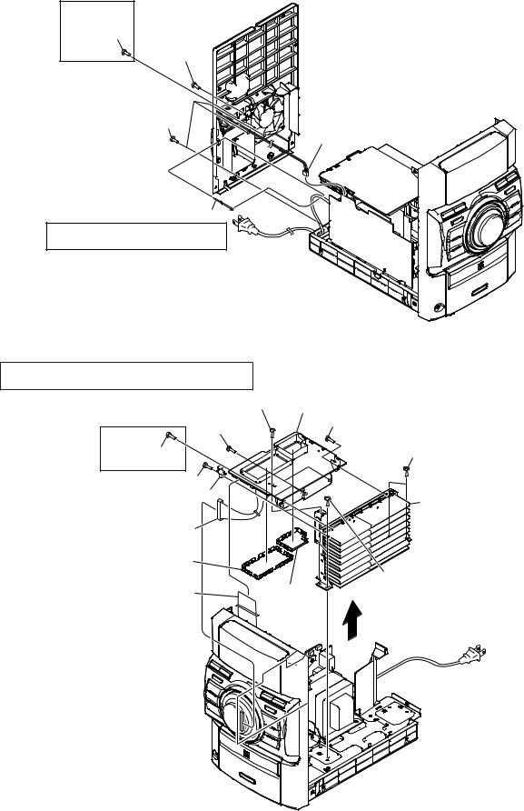
2-5. TOP PANEL BLOCK
7 top panel block |
|
|
|
|
4 two screws |
|
|
(BVTP3 u 10) |
6 two claws |
|
|
|
|
5 |
2 connector |
1 flexible flat cable (15 core) |
|
3 screw |
(S351) |
(CN401) |
(KTP3 u 10) |
|
|
3 screw (KTP3 u 10)
8
HCD-EC709iP/EC909iP
2-6. BACK PANEL BLOCK
(EC909iP)
3 screw (BVTP3 u 10)
3 screw 


 (BVTP3 u 10)


3 three screws (BVTP3 u 10)
1 Cut the wire holder.
Note: In reassembling, use new wire holder to fasten the wire holder same as before.
 4 back panel block
2fan connector (CN051)
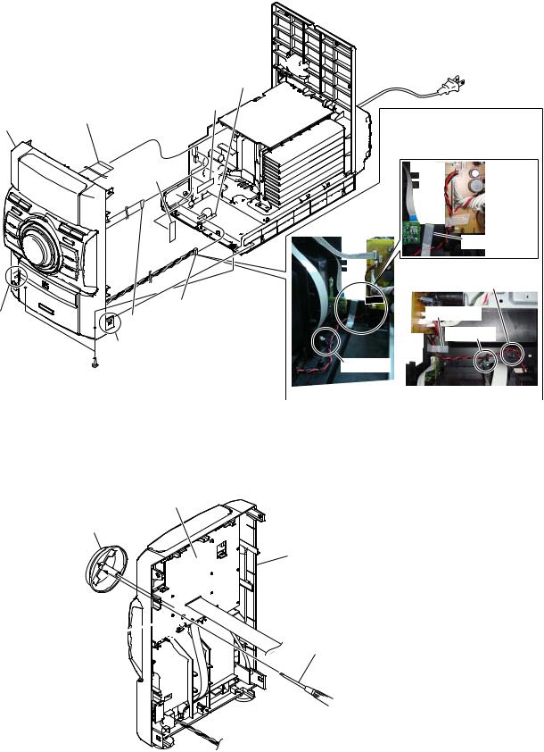
2-7. MAIN BOARD
Note: Cover (tuner top) and cover (function top) cannot re-used.
When these parts are removed, new parts must be replaced.
6 screw (BVTP3 u 10) |
qa MAIN board |
|||
5 two screws |
|
|
6 screw (BVTP3 u 10) |
|
|
(transistor) |
|
|
|
(EC909iP) |
|
|
|
|
|
|
|
|
|
5 two screws |
|
|
|
3 two screws |
(transistor) |
|
|
|
(BVTP3 u 10) |
|
|
|
|
|
6 screw (BVTP3 u 10) |
|
|
|
|
7 bracket (REG) |
|
|
8 heat sink block |
|
|
|
|
|
|
2 connector |
|
|
|
|
(CN101) |
|
|
|
|
0 cover (function top) |
|
|
|
|
|
|
|
|
3 two screws |
1 flexible flat cable (25 core) |
|
9 cover |
(BVTP3 u 10) |
|
|
|
(tuner top) |
|
|
(CN603) |
|
|
|
|
|
|
|
|
|
|
|
|
|
4 |
9
HCD-EC709iP/EC909iP
2-8. FRONT PANEL BLOCK
9 front panel block
8 claw
3 Remove clamping.
5 sheet
1 flexible flat cable (25 core) (CN603)
4 filament tape
6 connector (CN103)
2 flexible flat cable (5 core) (CN102)
8 claw
 7 two screws (BVTP3 u 10)
‡$UUDQJHPHQW RI OHDG ZLUH
Note 1: Confirm it is unquestionable for the open/close of the iPod dock after the lead wire is processed.
 sheet
sheet
filament tape
Note 2: Confirm the lead wire in this part does not stretch.
filament tape
clamp (L35)
clamp (L35)
– Side view – |
– Top view – |
2-9. KNOB (VOL)
Note: This illustration sees the front panel block from PANEL board side.
PANEL board
2 knob (VOL)
front panel block
hole 

1 Push the knob (VOL) by flat-head screwdriver.
10
HCD-EC709iP/EC909iP
2-10. BASE UNIT (BU-D1BD73)
Note 1: This illustration sees the top panel block from base unit side.
5two vibration proof rubbers (green)
1 four floating screws 
 (PTPWHM2.6)
8base unit (BU-D1BD73)
3
(EC709iP)
2 stopper (D1)
4two vibration proof rubbers (red)
6four claws
Note 2: Four claws might be fixed by bond.
7 cover (D1)
2-11. OPTICAL PICK-UP BLOCK (DA11MMVGP)
Note 1: When disconnecting the wire (flat type) (16 core) of optical pick-up block, solder the short-land.
5 tapping screw (P2)
7 optical pick-up block (DA11MMVGP)
2 Solder the short-land.
Note 2: When assembling the optical pick-up block, remove the solder of short-land after connecting the wire (flat type) (16 core).
6 shaft (support)
3 wire (flat type) (16 core) (optical pick-up)
4 BD73 board block
1 Remove four solders.
11

HCD-EC709iP/EC909iP
SECTION 3
TEST MODE
COLD RESET
The cold reset clears all data including preset data stored in the memory to initial conditions. Execute this mode when returning the set to the customer.
Procedure:
1.In the standby status, press the [?/1] button to turn the power on.
2.Press three buttons of [x], [CD] and [?/1] simultaneously.
3.When “RESET” appears, the set enters standby status.
PANEL TEST MODE
Enter The Panel Test Mode
Procedure:
1.In the standby status, press the [?/1] button to turn the power on.
2.Press three buttons of [x], [iPod & iPhone] and [?/1] simultaneously.
3.When the panel test mode is activated, LEDs and segments of the liquid crystal display are all turned on.
Version Check
Procedure:
1.In the panel test mode (all LEDs and segments of the liquid crystal display are turned on), press the [FUNCTION] button.
2.On the liquid crystal display, date and version are displayed “XXXXXXX”.
3.From this status, press the [u] button, and the destination and model name are displayed.
4.To release from this mode, press three button of [x], [iPod & iPhone] and [?/1] simultaneously.
Key Test Mode
Procedure:
1.In the panel test mode (all LEDs and segments of the liquid crystal display are turned on), press the [x] button.
2.The message “KEY0 0 0”displayed. Whenever any buttons are pressed and the [VOLUME] dial is turned, the value is changed.
3.To release from this mode, press three button of [x], [iPod & iPhone] and [?/1] simultaneously.
CD POWER MANAGE
This mode is for switch the CD power supply on/off. Even if this state pulls out AC plug, it is held.
Procedure:
1.Press the [?/1] button to turn the power on.
2.Press the [FUNCTION] button to select CD function.
3.Press the [?/1] button again to turn the power off (standby).
4.After pressing the [DISPLAY] button on the remote commander, while pressing the [x] button, press the [?/1] button.
5.It turns power on and display “PWR ON” or “PWR OFF”.
CHANGE-OVER THE AM TUNING INTERVAL
The AM tuning interval can be changed over 9 kHz or 10 kHz.
Procedure:
1.Press the [?/1] button to turn the power on.
2.Press the [FUNCTION] button to select TUNER (AM) function.
3.Press the [?/1] button again to turn the power off (standby).
4.After pressing the [DISPLAY] button on the remote commander, while pressing the [TUNING + M L] button, press the [?/1] button.
5.It turns power on and display “9k STEP” or “10k STEP”, and thus the tuning interval is changed over.
CD SERVICE MODE
This mode can move the SLED of the optical pick-up, and also can turn the optical pick-up laser power on and off.
Procedure:
1.Press the [?/1] button to turn the power on.
2.Press three buttons of [u], [ +] and [?/1] simultaneously.
3.Press the [FUNCTION] button to select CD function.
4.It enters the CD service mode and displays “SERVICE”.
5.To exit from this mode, press three buttons of [u], [ +] and [?/1] simultaneously.
Key Operation:
[TUNING + M L], [– TUNING l m]:
Use these keys to move the SLED. When [TUNING + M L] is pressed in this mode, the SLED moves to outer circumference and the message “SLED OUT” is displayed.
When [– TUNING l m] is pressed in this mode, the SLED moves to inner circumference and the message “SLED IN” is displayed.
[CD]:
Use this key to turn the optical pick-up laser power on and off. When the laser power is turned on, the message “LD ON” is displayed. When the laser power is turned off, the message “LD OFF” is displayed.
CD FACTORY MODE
Note 1: Do not enter the this mode while any other test mode is in progress.
Note 2: Do not enter any other test mode while the this mode is in progress.
Procedure:
1.Press the [?/1] button to turn the power on.
2.Press the [FUNCTION] button to select CD function
3.Press three buttons of [u], [iPod & iPhone] and [?/1] simultaneously.
4.It enters the CD factory mode and the message “FACTORY” is displayed. When the [CD] button is pressed, the following message (initial display) is displayed.
– – ON
S character mode setting
Tracking servo setting
RF gain setting
Key Operation:
[CD]:
The display changes in the following order whenever the button is pressed.
(Initialdisplay)
FCSAG**(**:FocusAGCvalue)
TRKAG**(**:TrackAGCvalue)
 RF_AG**(**:RFAGCvalue)
[DSGX]:
RF gain setting changes whenever the button is pressed. “–”: No gain fixation.
“AL”: Fix to the gain for AL disc. “RW”: Fix to the gain for RW disc.
12
[iPod & iPhone]:
Tracking servo setting changes whenever the button is pressed (This function is executable only while CD is playing).
“ON”: Tracking servo ON. “OFF”: Tracking servo OFF.
[FUNCTION]:
S character mode setting changes whenever the button is pressed. “ ”: S character mode OFF.
“S”: S character mode ON.
5.To release from this mode, press three buttons of [u], [iPod & iPhone] and [?/1] simultaneously.
HCD-EC709iP/EC909iP
SECTION 4
ELECTRICAL CHECK
Note:
1.CD Block is basically constructed to operate without adjustment.
2.Use YEDS-18 disc (Part No. 3-702-101-01) unless otherwise indicated.
3.Use an oscilloscope with more than 10 M: impedance.
4.Clean the object lens by an applicator with neutral detergent when the signal level is low than specified value with the following checks.
5.Check the focus bias check when optical pick-up block is replaced.
FOCUS BIAS CHECK
oscilloscope (DC range)
BD73 board
CL102 (RFOUT)
 +
+
CL117 (VREF) 
 –
–
Procedure:
1.Connect the oscilloscope to CL102 (RFOUT) and CL117 (VREF) on the CD board.
2.Press the [?/1] button to turn the power on, and press the [FUNCTION] button to select CD function.
3.Set disc (YEDS-18) and press the [u] button to playback.
4.Confirm that oscilloscope waveform is as shown in the figure below (eye pattern).
A good eye pattern means that the diamond shape (¡) in the center of the waveform can be clearly distinguished.
VOLT/DIV: 200 mV
TIME/DIV: 500 ns
level:
1.1 ± 0.4 Vp-p
Checking Location:
– BD73 Board (Conductor Side) –
CL117
(VREF)
CL102
(RFOUT)
IC101
HCD-EC709iP/EC909iP
13 13

HCD-EC709iP/EC909iP
SECTION 5
DIAGRAMS
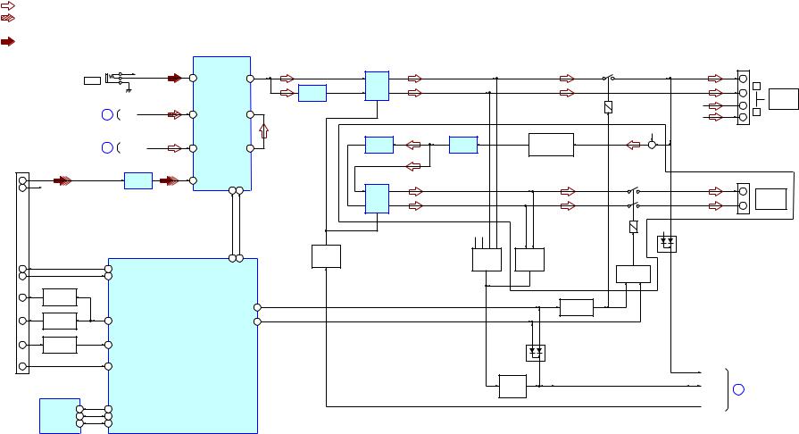
5-1. BLOCK DIAGRAM - CD SERVO, TUNER Section -
FK/DVVDPHWRGXHRPLWWHGLVFK5‡ 36,*1‡$/$7+
:TUNER(FM/AM)
:CDPLAY
OPTICALPICK-UPBLOCK (DA11MMVGP)
A |
|
|
|
|
B |
|
|
|
|
C |
|
|
|
|
D |
|
|
|
|
E |
|
|
|
|
F |
|
|
|
|
|
AUTOMATIC |
|
|
|
LD |
POWER |
|
|
|
CONTROL |
|
|
||
|
|
|
||
|
|
Q201 |
|
|
MD |
|
|
|
|
VREF |
|
|
|
|
|
FOCUS/TRACKINGCOILDRIVE, |
|||
|
SLED/SPINDLEMOTORDRIVE |
|||
|
|
IC301 |
|
|
|
|
|
BIAS 23 |
|
SP+ |
2 |
VO1+ |
IN1 |
3 |
SP- |
1 |
VO1- |
|
|
SL+ |
11 |
VO2+ |
IN2’ |
9 |
SL- |
12 |
VO2- |
|
|
T+ |
18 |
VO3+ |
IN3’ 20 |
|
T- |
17 |
VO3- |
|
|
F+ |
26 |
VO4+ |
IN4’ 24 |
|
F- |
27 |
VO4- |
|
|
CN082
ANTENNA
FM/AM
3BAND-PASS
FILTER  30 FMANT
FL081
L081
1
 1 AMANT
3 AMVt
CD-MP3PROCESSOR
IC101
5 |
AIN |
LCHO 76 |
CD-L |
A (Page 15) |
|
7 |
BIN |
||||
RCHO 78 |
R-CH |
|
|||
|
|
|
|||
6 |
CIN |
|
|
|
|
8 |
DIN |
|
|
|
|
13 |
EIN |
|
|
|
|
14 |
FIN |
CE 43 |
|
|
|
|
|
CL 44 |
|
|
|
|
|
DI 45 |
|
|
|
|
|
DO 46 |
|
|
|
18 |
LDD |
RESB 47 |
|
|
|
19 |
LDS |
|
|
|
|
11 |
VREF |
|
|
|
|
|
|
|
S001 |
|
|
|
|
|
(LIMIT) |
|
|
|
LIMIT-SW(CONT3) 32 |
|
|
||
25 |
SPDO |
|
|
|
|
|
|
XOUT 72 |
|
|
|
24 |
SLDO |
|
X101 |
|
|
|
16.934MHz |
|
|||
|
|
XIN 73 |
|
||
|
|
|
|
||
23 |
TDO |
|
|
|
|
22 |
FDO |
|
|
|
|
MUTE 7 
AM/FM-DET, OSC, MIX, PLL, IFAMP
IC081
SDOUT
CE
CL
DO
DI
20 21 19 18 13
56 48 57 55 39
I-TU-ANSD
O-TU-CE
O-TU-CLK
I-TU-DO
O-TU-DI
SYSTEMCONTROLLER
IC301 (1/3)
17 O-CD-CE
18 O-CD-CL
20 O-CD-DO  19 I-CD-DI
24 O-CD-RESB
I-CDM-OPEN_CLOSE 7 
23 O-CD-M-MUTE
L-OUT |
9 |
|
|
TUNER-L |
B |
|
|
||||
R-OUT |
10 |
|
R-CH |
(Page 15) |
|
|
|
||||
CLKIN
16
X081
32.768kHz
S351
(CDLIDOPEN/CLOSEDETECT)
HCD-EC709iP/EC909iP
14 14
HCD-EC709iP/EC909iP
5-2. BLOCK DIAGRAM - MAIN Section -
 R-ch is omitted due to same as L-ch.
  SIGNAL PATH
: TUNER (FM/AM)
: CD PLAY
 : iPod & iPhone : PC IN
ELECTRICAL VOLUME, INPUT SELECTOR
|
|
|
|
|
|
|
IC601 |
|
|
|
|
|
|
|
|
|
|
|
|
|
|
|
|
|
|
|
|
|
|
|
|
|
|
RY701 |
|
TB701 |
|
|
|
|
J491 |
|
|
|
|
|
|
|
|
|
|
|
|
|
|
|
|
|
|
|
R-CH |
8 |
AUDIO-L |
OUT-L |
19 |
|
|
|
|
|
|
+ |
|
||
|
|
|
PC IN |
|
|
|
POWER |
|
|
|
|
|
||||||
|
|
|
|
|
|
|
|
|
|
|
INVERTER |
AMP |
|
|
|
|
– |
L |
|
|
|
|
|
|
|
|
|
|
|
IC604 |
|
|
|
|
SPEAKERS |
||
|
|
|
|
|
|
|
|
|
|
|
IC603 |
|
|
|
|
|||
|
|
|
|
|
|
|
|
|
|
|
|
|
|
|
|
|
ONLY FOR |
|
|
|
|
|
|
|
|
|
|
|
|
|
|
|
|
|
|
|
|
|
|
|
|
|
|
|
|
|
|
|
|
|
|
|
R-CH |
|
+ |
SS-EC709iP |
|
|
(Page 14) |
A |
CD-L |
6 |
CD-L |
VOL-L |
12 |
|
|
|
|
R-CH |
|
– |
R |
||
|
|
|
|
|
|
|
|
|||||||||||
|
|
|
|
|
|
|
|
|
|
|
|
(EC909iP) |
|
|
R-CH |
|
|
|
|
|
|
|
|
|
|
|
|
|
|
|
INVERTER |
BUFFER |
SUBWOOFER |
+ |
|
|
|
|
|
|
|
|
|
|
|
|
|
|
|
BAND-PASS FILTER |
|
|
|
|||
|
|
(Page 14) |
B |
TUNER-L |
4 |
TUNER-L |
SEL-L |
9 |
|
IC605 (1/2) |
IC605 (2/2) |
|
|
|
||||
|
|
|
Q803, 804 |
|
|
|
|
|||||||||||
|
|
|
|
|
|
|
|
|
|
|
|
|
|
|
|
|
|
|
|
CN902 |
|
|
|
|
|
|
|
|
|
|
|
|
|
|
|
|
|
(iPod/iPhone CONNECTOR) |
|
|
|
|
|
SDATA |
SCLK |
|
|
|
|
|
|
|
|
|
||
|
|
|
|
|
IC602 |
|
|
|
|
|
|
|
RY801 |
|
|
|
||
LINE-OUT-L 27 |
|
|
|
LINE AMP |
2 |
iPod-L |
|
|
|
|
|
|
|
|
|
TB801 |
||
|
|
|
|
|
|
|
|
|
|
|
|
|
||||||
|
|
|
|
|
|
|
|
|
|
|
|
|
|
|
||||
LINE-OUT-R |
28 |
R-CH |
|
|
|
|
|
26 25 |
|
|
POWER |
|
|
|
|
+ |
SUBWOOFER |
|
|
|
|
|
|
|
|
|
|
|
|
|
|
|
|||||
|
|
|
|
|
|
|
|
|
|
|
|
AMP |
|
|
|
|
– |
ONLY FOR |
|
|
|
|
|
|
|
|
|
|
|
|
IC606 |
|
|
|
|
SS-WG909iP |
|
|
|
|
|
|
|
|
|
|
|
|
|
|
R-CH |
|
R-CH |
|
|
|
|
|
|
|
|
|
|
|
|
|
|
|
|
|
|
|
|
|
|
|
|
|
|
|
|
|
|
|
|
|
|
|
|
|
D705 |
|
|
|
|
|
|
|
|
|
|
|
|
|
|
STANDBY |
|
OVER LOAD |
OVER LOAD |
|
|
|
|
|
|
|
|
|
|
|
|
33 |
34 |
|
SWITCH |
|
|
|
|
|
||
|
|
|
|
|
|
|
|
|
|
DETECT |
DETECT |
|
|
|
|
|||
|
|
|
|
|
|
|
|
|
Q604 |
|
|
|
|
|
||||
|
|
|
|
|
|
|
|
|
|
|
|
|
|
|
|
|||
|
|
|
|
|
|
|
|
AUDIO-O-DATA |
AUDIO-O -CLK |
|
|
Q701 - 704 |
Q805, 806 |
|
|
|
|
|
RXD |
18 |
|
|
31 |
O-iPod-RXD |
|
|
|
|
|
|
|
|
|
||||
|
|
|
|
|
|
|
|
|
RELAY DRIVE |
|
|
|
||||||
TXD |
|
|
|
|
|
SYSTEM CONTROLLER |
|
|
|
|
|
|
|
|
||||
19 |
|
|
29 |
I-iPod-TXD |
|
|
|
|
|
Q601, 602 |
|
|
|
|||||
Acc ID |
10 |
BUFFER |
|
|
|
IC301 (2/3) |
|
|
|
|
|
|
|
|
|
|
|
|
Q901 |
|
|
|
|
|
|
|
|
|
|
|
|
|
|
|
|||
|
|
|
|
|
|
|
|
|
|
|
|
|
RELAY DRIVE |
|
|
|
|
|
|
|
|
|
|
|
|
|
O-SP-RELAY |
2 |
|
|
|
|
|
|
|||
|
|
|
|
|
|
|
|
|
|
Q603 |
|
|
|
|
||||
|
|
|
|
|
|
|
|
|
|
|
|
|
|
|
|
|
|
|
Acc DET |
20 |
BUFFER |
|
21 |
O-iPhone-DET-CTL |
|
O-SUBWOOFER-ON/NC |
6 |
|
|
|
|
|
|
|
|||
Q902 |
|
|
|
|
|
|
|
|
|
|||||||||
|
|
|
|
|
|
|
|
|
|
|
|
|
|
|
|
|
|
|
Acc PWR |
13 |
WAKE UP |
|
22 |
I-iPod-ACCP |
|
|
|
|
|
|
|
|
|
|
|
|
|
Q310 |
|
|
|
|
|
|
|
|
|
|
|
|
|
|
||||
|
|
|
|
|
|
|
|
|
|
|
|
|
D601 |
|
|
|
|
|
|
|
|
|
|
|
|
|
|
|
|
|
|
|
|
|
|
|
|
DGND |
30 |
|
|
45 |
I-iPod-DET |
|
|
|
|
|
|
|
|
|
|
|
|
|
|
|
|
|
|
|
|
|
|
|
|
|
|
|
|
|
FAN-CONT |
|
|
|
|
|
|
|
|
|
|
|
|
|
|
|
|
PROTECT |
|
|
|
|
|
|
EEPROM |
|
|
|
|
|
|
|
|
|
|
|
DETECT |
|
PROTECT |
C |
(Page 16) |
|
|
IC901 |
|
|
|
|
|
|
|
|
|
|
|
Q605, 606 |
|
|
||
|
|
|
|
|
|
|
|
|
|
|
|
|
|
|
|
|
||
|
|
RESET |
4 |
30 O-iPod-CP-RESET |
|
|
|
|
|
|
|
|
|
|
O-POWER |
|
|
|
|
|
|
|
|
|
|
|
|
|
|
|
|
|
|
||||
|
|
I2C-SDA |
13 |
49 I/O-iPhone-CP-DATA |
|
|
|
|
|
|
|
|
|
|
|
|
|
|
|
|
I2C-SCL |
12 |
50 |
I/O-iPhone-CP-CLK |
|
|
|
|
|
|
|
|
|
|
|
|
|
HCD-EC709iP/EC909iP
15 15
HCD-EC709iP/EC909iP
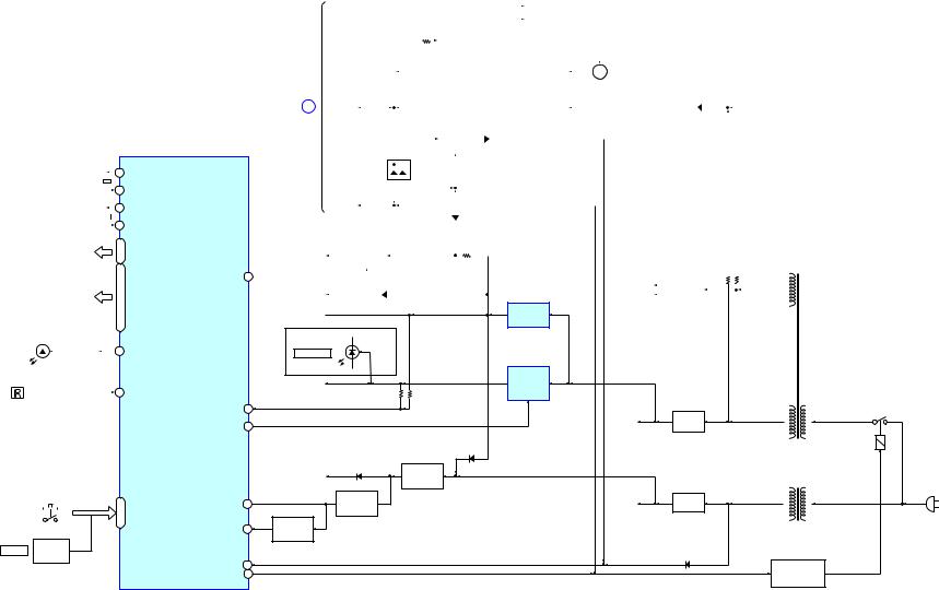
5-3. BLOCK DIAGRAM - PANEL, POWER SUPPLY Section -
|
|
|
|
|
|
|
X301 |
|
|
|
|
14 X1A |
|||||
|
|
|
|
|
|
|
|
|
|
|
|
|
|||||
|
|
|
|
|
|
|
32.768kHz |
|
|
|
|
13 X0A |
|||||
|
|
|
|
|
|
|
|
X302 |
|
|
|
|
92 X1 |
||||
|
|
|
|
|
|
|
|
6MHz |
|
|
|
|
93 X0 |
||||
|
|
|
|
|
|
|
|
|
|
|
|
|
|
|
|||
|
|
|
|
|
|
|
|
|
|
|
|
62 |
COM0,COM1, |
||||
|
|
|
|
|
|
|
|
|
|
|
|
||||||
|
|
|
|
|
|
|
|
|
|
|
|
- |
CMO2,CMO3 |
||||
|
|
|
|
|
|
|
|
|
|
|
|
59 |
|||||
|
|
|
|
|
|
|
LCD301 |
|
|
|
|
|
|
||||
|
|
|
|
|
|
|
LIQUID |
|
1 |
|
|||||||
|
|
|
|
|
|
|
DISPLAY |
|
100,- |
|
|||||||
|
|
|
|
|
|
|
CRYSTAL |
|
|
|
|
|
|
||||
|
|
|
|
|
|
|
|
|
|
|
|
94 |
SEG0-SEG32 |
||||
|
|
|
|
|
|
|
|
|
|
|
|
64, 67 - 89, |
|||||
|
|
|
|
|
|
|
|
|
|
|
|
|
|||||
|
D303 |
|
|||||||||||||||
|
63, |
SYSTEMCONTROLLER |
|||||||||||||||
(LCDBACKLIGHT) |
|||||||||||||||||
|
|
|
|
IC301 (3/3) |
|||||||||||||
|
|
|
|
|
|
|
|
|
|
|
|
|
|
|
|
||
|
|
|
|
|
|
|
|
|
|
|
|
|
|
|
|||
|
|
|
|
|
|
|
LEDDRIVE |
|
|
|
28 |
O-LED |
|||||
|
|
|
|
|
|
|
Q301 |
|
|
|
|||||||
|
|
|
|
|
|
|
|
|
|
|
|
|
|||||
|
|
|
|
|
|
|
|
|
|
|
|
|
|
|
|
||
|
|
|
|
|
|
|
|
|
|
|
|
|
|
|
|
|
|
|
|
|
|
|
|
|
|
|
|
|
|
|
|
|
|
|
|
|
REMOTECONTROL |
|
|
|
|
|
|
|
|
|
|||||||
|
|
|
RECEIVER |
|
|
|
|
9 |
I-RMC |
||||||||
|
|
|
|
|
IC302 |
|
|
|
|
|
|
|
|
||||
S301 (EC909iP),
S302 (EC709iP),
S310 - 314,
S315 (EC909iP),
S320 - 324
(FRONTPANELKEYS)
|
|
|
|
|
|
|
|
|
41 |
I-KEY1, I-KEY2, |
|
|
|
|
|
|
|
|
|
38, |
|
|
|
|
|
|
|
|
|
|
I-KEY-WAKE-UP/VOL |
|
|
|
|
|
|
|
|
|
|
37, |
|
|
|
|
|
|
|
|
|
|
|
|
|
|
|
|
|
|
|
|
|
|
|
ROTARY
VOLUME ENCODER
S304
|
|
|
FAN-CONT |
|
|
|
|
|
|
|
|
|
|
|
|
|
|
|
|
|
|
|
|
|
|
|
|
|
|
|
FANMOTOR |
|
|
|
|
|
|
|
|
|
|
|
|
|
|
|
|
|
|
|
|
|
|
|
|
|
|
|
|
|
|
|
|
|
|
|
|
|
|
|
|
|
|
|
|
|
|
|
|
|
|
|
|
|
|
|
|
|
|
|
|
|
|
||||
|
|
|
|
|
|
|
|
|
|
|
|
|
|
|
|
|
|
|
|
|
|
|
|
|
|
|
|
|
|
|
|
DRIVE |
|
|
|
|
|
|
|
|
|
|
|
|
|
|
|
|
|
|
|
|
|
|
|
|
|
|
|
|
|
|
|
|
|
|
|
|
|
|
|
|
|
|
|
|
|
|
|
|
Q052-054 |
|
|
|
|
|
|
|
|
|
|
|
|
|
|
|
|
|
|
|
|
|
|
|
|
|
|
|
|
|
|
|
|
|
|
|
|
|
+9V |
|
|
|
|
|
|
|
|
|
|
|
|
|
|
|
|
|
|
|
|
|
|
|||||
|
|
|
|
|
|
|
|
|
|
|
|
|
|
|
+9V |
|
|
|
DETECT |
|
|
|
|
|
|
|
|
|
|
|
|
|
|
|
|
|
|
|
|
|
|
|||||||
|
|
|
|
|
|
|
|
|
|
|
|
|
|
|
|
|
|
|
|
|
|
|
|
|
|
|
|
|
|
|
|
|
|
|
|
|
|
|
|
|||||||||
|
|
|
|
|
|
|
|
|
|
|
|
|
|
|
|
|
|
|
|
|
|
|
|
|
|
|
|
|
|
|
|
|
|
|
|
|||||||||||||
|
|
|
|
|
|
|
|
|
|
|
|
|
|
|
|
|
|
|
|
|
Q051 |
|
|
|
|
|
|
|
|
|
|
|
|
|
|
|
|
|
|
|
|
|
|
|||||
|
|
|
|
|
|
|
|
|
|
|
|
|
|
|
|
|
|
|
|
|
|
|
|
|
|
|
|
|
|
|
|
|
|
|
|
|
|
|
|
|
|
|
||||||
|
|
|
|
|
|
|
|
|
|
|
|
|
|
|
|
|
|
|
|
|
|
|
|
|
|
|
|
|
|
|
|
|
|
|
|
|
|
|
|
|
|
|
|
|
|
|
|
|
|
|
|
|
|
|
|
|
|
|
|
|
|
|
|
|
|
|
|
|
|
|
|
|
|
|
|
|
|
|
|
|
|
|
|
|
|
|
|
|
|
|
|
|
|
|
|
|
|
|
|
|
|
|
|
|
|
|
|
|
|
|
|
|
|
|
|
|
|
|
|
|
|
|
|
|
|
|
|
|
|
FANPROTECT |
|
|
|
|
|
M001 |
|
|
|
|
|
|
|
|
|
|
|
|
|
|
|
|
|
|
|
|
|
|
|
|
|
|
|
|
|
|
|
|
|
|
|
|
|
|
|
|
|
|
DETECT |
|
|
M |
|
|
|
|
|
|
|
|
|
|
|||
|
|
|
|
|
|
|
|
|
|
|
|
|
|
|
|
|
|
|
|
|
|
|
|
|
|
|
|
|
|
|
|
Q071-073 |
|
|
|
|
|
(FAN) |
|
|
|
|
|
|
|
|
|
|
|
|
|
|
|
|
|
|
|
|
|
|
|
|
|
|
|
|
|
|
|
|
|
|
|
|
|
|
|
|
|
|
|
|
|
|
|
|
|
|
|
|
|
|
|
|
|
|
|
|
|
|
|
|
|
|
|
|
|
|
|
|
|
|
|
|
|
|
|
|
|
|
|
|
|
|
|
|
|
|
|
|
|
|
|
|
|
|
|
D106,107 |
||||||||
|
|
|
|
|
|
|
|
|
|
|
|
|
|
|
|
|
|
|
|
|
|
|
|
|
|
|
|
|
|
|
|
|
|
|
|
|
|
|
|
|||||||||
|
(Page 15) C |
|
|
|
|
|
|
|
|
|
|
|
|
|
|
|
|
|
|
|
|
|
|
|
|
|
|
|
|
|
|
AC |
|
|
|
|
|
|
|
|||||||||
|
|
PROTECT |
|
|
|
|
|
|
|
|
|
|
|
|
|
|
|
|
|
|
|
|
|
|
|
|
|
|
|
DETECT |
|
|
|
|
|
|
|
|
|
|
|
|
|
|
|
|
||
|
|
|
|
|
|
|
|
|
|
|
|
|
|
|
|
|
|
|
|
|
|
|
|
|
|
|
|
|
|
|
|
Q101,102 |
|
|
|
|
|
|
|
|
|
|
|
|
|
|
|
|
|
|
|
|
|
|
|
|
|
|
|
|
|
|
|
|
|
|
|
|
|
|
|
|
|
|
|
|
|
|
|
|
|
|
|
|
|
|
|
|
|
|
|
|
|
|
|
|
|
|
|
|
|
|
|
|
|
|
|
|
|
|
|
|
|
|
|
|
|
|
|
D110 |
|
|
|
|
|
|
|
|
|
|
|
|
|
|
|
|
||||||||||
|
|
|
|
|
|
|
|
|
|
|
|
|
|
|
|
|
|
|
|
|
PROTECT |
|
|
|
|
|
|
|
|
|
|
|
|
|
|
|
|
|||||||||||
|
|
|
|
|
|
|
|
|
|
|
|
|
|
|
|
+9V |
|
|
DETECT |
|
|
|
|
|
|
|
|
|
|
|
|
|
|
|
|
|
|
|
|
|
|
|||||||
|
|
|
|
|
|
|
|
|
|
|
|
|
|
|
|
D111 |
|
Q103 |
|
|
|
|
|
|
|
|
|
|
|
|
|
|
|
|
|
|
|
|
‡ AEEUHYiDWiRQ |
|||||||||
|
|
|
|
|
|
|
|
|
|
|
|
|
|
|
|
|
|
|
|
|
|
|
|
|
|
|
|
|
|
|
|
|
|
|
|
|
|
|
|
|
|
|
||||||
|
|
|
|
|
|
|
|
|
|
|
|
|
|
|
|
|
|
|
|
|
|
|
|
|
|
|
|
|
|
|
|
|
|
|
|
|
|
|
|
|
|
|
||||||
|
|
|
|
|
|
|
|
|
|
|
|
|
|
|
|
|
|
|
|
|
|
|
|
|
|
|
|
|
|
|
|
|
|
|
|
|
|
|
|
|
|
|
|
|
|
|
||
|
|
|
|
|
|
|
|
|
|
|
|
|
|
|
|
|
|
|
|
|
|
|
|
|
|
|
|
|
|
|
|
|
|
|
|
|
|
|
|
|
|
|
|
|
|
|
||
|
|
|
O-POWER |
|
|
|
|
|
|
|
|
|
|
|
|
|
|
|
|
|
|
|
|
|
|
|
|
|
|
|
|
|
|
|
|
|
|
|
|
AUS :AXVWUDOiDQ PRGHO |
||||||||
|
|
|
|
|
|
|
|
|
|
|
|
|
|
|
|
|
|
|
|
D109 |
|
|
|
|
|
|
|
|
|
|
|
|
|
|
|
|
|
|
|
|
|
|
|
|
|
CND : CDQDGiDQ PRGHO |
||
|
|
|
|
|
|
|
|
|
|
|
|
|
|
|
|
|
|
|
|
|
|
|
|
|
|
|
|
|
|
|
|
|
|
|
|
|
|
|
|
|
|
|
|
|
||||
|
|
|
|
|
|
|
|
|
|
|
|
|
|
|
|
|
|
|
|
|
|
|
|
|
|
|
|
|
|
|
|
|
|
|
|
|
|
|
|
|
|
|
|
|
|
|
|
|
|
|
|
|
|
|
+3.3V |
|
|
|
|
|
|
|
|
|
|
|
|
|
|
|
|
|
|
|
|
|
|
|
|
|
|
|
|
|
|
|
|
|
|
|
|
|
|
PT004 |
|||
|
CD+3.3V |
|
|
REGULATOR |
|
|
|
|
|
|
|
|
|
|
|
|
|
|
|
|
|
|
|
|
|
|
|
|
|
|
|
|
|
|
|
|
|
|
MAINPOWER |
|||||||||
|
|
|
|
|
|
|
|
|
|
|
|
|
|
|
|
|
|
|
|
|
|
|
|
|
|
|
|
|
|
|
|
|
|
|
|
|
|
|
|
|||||||||
|
|
|
|
|
|
|
|
|
|
|
|
|
|
|
|
|
|
|
|
|
|
|
|
|
|
|
|
|
|
|
|
|
|
|
|
|||||||||||||
|
|
|
|
Q302,303 |
|
|
|
|
|
|
|
|
|
|
|
|
|
|
|
|
|
|
|
|
|
|
|
|
|
|
|
|
|
|
|
|
|
|
|
|
|
|||||||
|
|
|
|
|
|
|
|
|
|
|
|
|
|
|
|
|
|
|
|
|
|
|
|
|
|
|
|
|
|
|
|
|
|
|
|
|
|
TRANSFORMER |
||||||||||
|
|
|
|
|
|
|
|
|
|
|
|
|
|
|
|
|
|
|
|
|
|
|
|
|
|
|
|
|
|
|
|
|
|
|
|
|
|
|
|
|
|
|
|
|
|
|
||
O-CD-ON 4 |
|
|
|
|
|
|
D304,305 |
|
|
|
|
|
|
|
|
|
|
|
|
|
|
|
|
|
|
+B |
|
|
|
|
|
|
|
|
|
|
||||||||||||
|
|
|
|
|
|
|
|
|
|
|
|
|
|
|
|
|
|
|
|
|
|
|
|
|
|
|
|
|
|
|
|
|
|
|||||||||||||||
|
|
|
|
|
|
|
|
|
|
|
|
|
|
|
|
|
|
|
|
|
|
|
|
|
|
RECT |
|
|
|
|
|
|
||||||||||||||||
|
VM7V |
|
|
|
|
|
|
|
|
|
|
|
|
|
|
|
|
|
|
|
|
|
|
|
|
|
|
|
|
|
|
|
|
|
|
|
|
-B |
|
D101 |
|
|
|
|
|
|
||
|
|
|
+9V |
|
|
+9V |
|
REGULATOR |
|
|
NDICATOR) |
|
IC611 |
|
|
(EC909iP) |
|
|
|
|
D902,906 |
|
|
|
|
DRFk IRU iPRG |
|
|
|
|
(iPRG I |
|
|
|
|
|
|
DC/DC |
|
|
VBUS_5V |
|
CONVERTER |
|
|
|
IC151, |
|
|
|
|
|
|
|
|
|
|
Q151155 |
|
I-5V/9V-DET 40 |
|
|
|
RY001 |
|
|
|
|
|
|
|
|
UNREG |
RECT |
O-5V-ON 11 |
|
|
D102 - 105 |
|
|
|
|
||
|
|
|
D311 |
|
|
|
|
|
PT001(EC709iP:US,CND/EC909iP:US,CND) |
|
D308 |
+4V |
|
PT002(EC709iP:AUS/EC909iP:AUS) |
|
|
|
SUBPOWER |
|
|
SYSTEM+3.3V |
REGULATOR |
|
|
|
|
TRANSFORMER |
||
|
|
Q304,306 |
|
|
|
|
|
|
|
|
VOLTAGE |
|
|
(AC IN) |
|
|
|
RECT |
|
I-HOLD 42 |
DETECT |
|
V-STBY |
|
|
D001,002 |
|||
|
Q305,308 |
|
|
|
|
|
|
|
|
|
RESET |
|
|
|
I-RST 54 |
SWITCH |
|
|
|
|
Q309 |
|
|
|
|
|
|
|
D003 |
I-P-MONI 36 |
|
|
|
MAINPOWER |
O-POWER 3 |
|
|
|
ON/OFFCONTROL |
|
|
|
|
Q104 |
HCD-EC709iP/EC909iP
16 16
 Loading...