


GDM-D300E
GV-D300/D300E/D900/D900E
US Model
Canadian Model
GV-D300/D900
AEP Model
UK Model
E Model
GV-D300E/D900E
SERVICE MANUAL
DIGITAL VIDEO CASSETTE RECORDER
MICROFILM
D200 MECHANISM
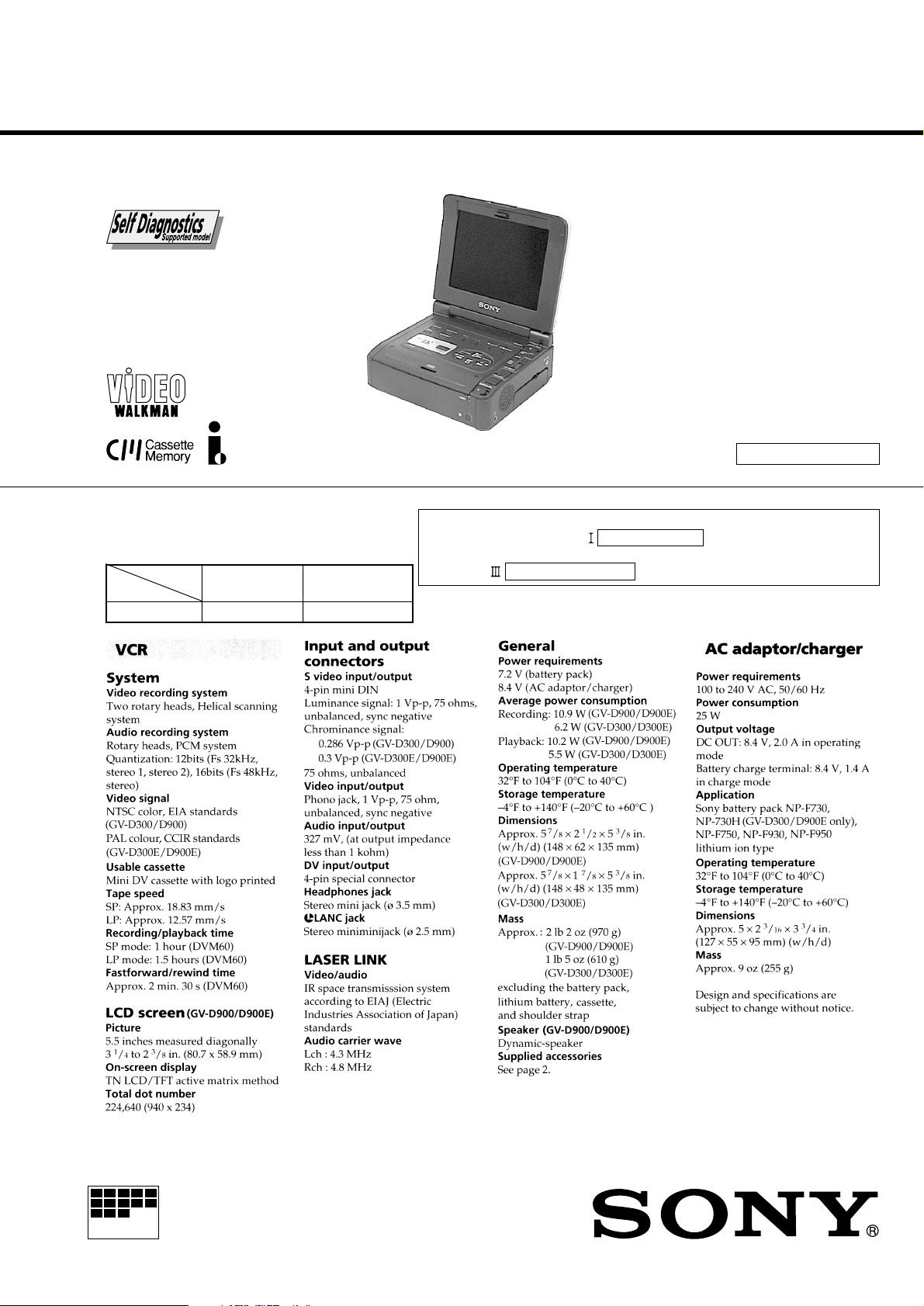
SPECIFICATIONS
For MECHANISM ADJUSTMENTS, refer to the “DV MECHANICAL
ADJUSTMENT MANUAL D MECHANISM ” (original: 9-973-815-11),
supplement: 9-973-815-81) and “DV MECHANICAL ADJUSTMENT
MANUAL
D200 MECHANISM ” (original: 9-973-981-11).
Photo: GV-D900E
GV-D300/D900: NTSC
GV-D300E/D900E: PAL
Function difference table
Model
Function
LCD
GV-D300/300E
—
GV-D900/D900E
5.5 inches
Ver 1.6 2003.06
With SUPPLEMENT-1 (9-974-068-81)
With SUPPLEMENT-2 (9-974-068-82)
With CORRECTION-2 (9-974-068-92)
With SUPPLEMENT-3 (9-974-068-83)
— 2 —
SAFETY-RELATED COMPONENT WARNING!!
COMPONENTS IDENTIFIED BY MARK ! OR DO TTED LINE WITH
MARK ! ON THE SCHEMATIC DIAGRAMS AND IN THE PARTS
LIST ARE CRITICAL TO SAFE OPERATION. REPLACE THESE
COMPONENTS WITH SONY PARTS WHOSE PART NUMBERS
APPEAR AS SHOWN IN THIS MANUAL OR IN SUPPLEMENTS
PUBLISHED BY SONY.
ATTENTION AU COMPOSANT AYANT RAPPORT
À LA SÉCURITÉ!
LES COMPOSANTS IDENTIFÉS P AR UNE MARQUE ! SUR LES
DIAGRAMMES SCHÉMA TIQUES ET LA LISTE DES PIÈCES SONT
CRITIQUES POUR LA SÉCURITÉ DE FONCTIONNEMENT. NE
REMPLACER CES COMPOSANTS QUE PAR DES PIÈSES SONY
DONT LES NUMÉROS SONT DONNÉS DANS CE MANUEL OU
DANS LES SUPPÉMENTS PUBLIÉS PAR SONY.
1. Check the area of your repair for unsoldered or poorly-soldered
connections. Check the entire board surface for solder splashes
and bridges.
2. Check the interboard wiring to ensure that no wires are
"pinched" or contact high-wattage resistors.
3. Look for unauthorized replacement parts, particularly
transistors, that were installed during a previous repair . Point
them out to the customer and recommend their replacement.
4. Look for parts which, through functioning, show obvious signs
of deterioration. Point them out to the customer and
recommend their replacement.
5. Check the B+ voltage to see it is at the values specified.
6. Flexible Circuit Board Repairing
• Keep the temperature of the soldering iron around 270˚C
during repairing.
• Do not touch the soldering iron on the same conductor of the
circuit board (within 3 times).
• Be careful not to apply force on the conductor when soldering
or unsoldering.
SAFETY CHECK-OUT
After correcting the original service problem, perform the following
safety checks before releasing the set to the customer.
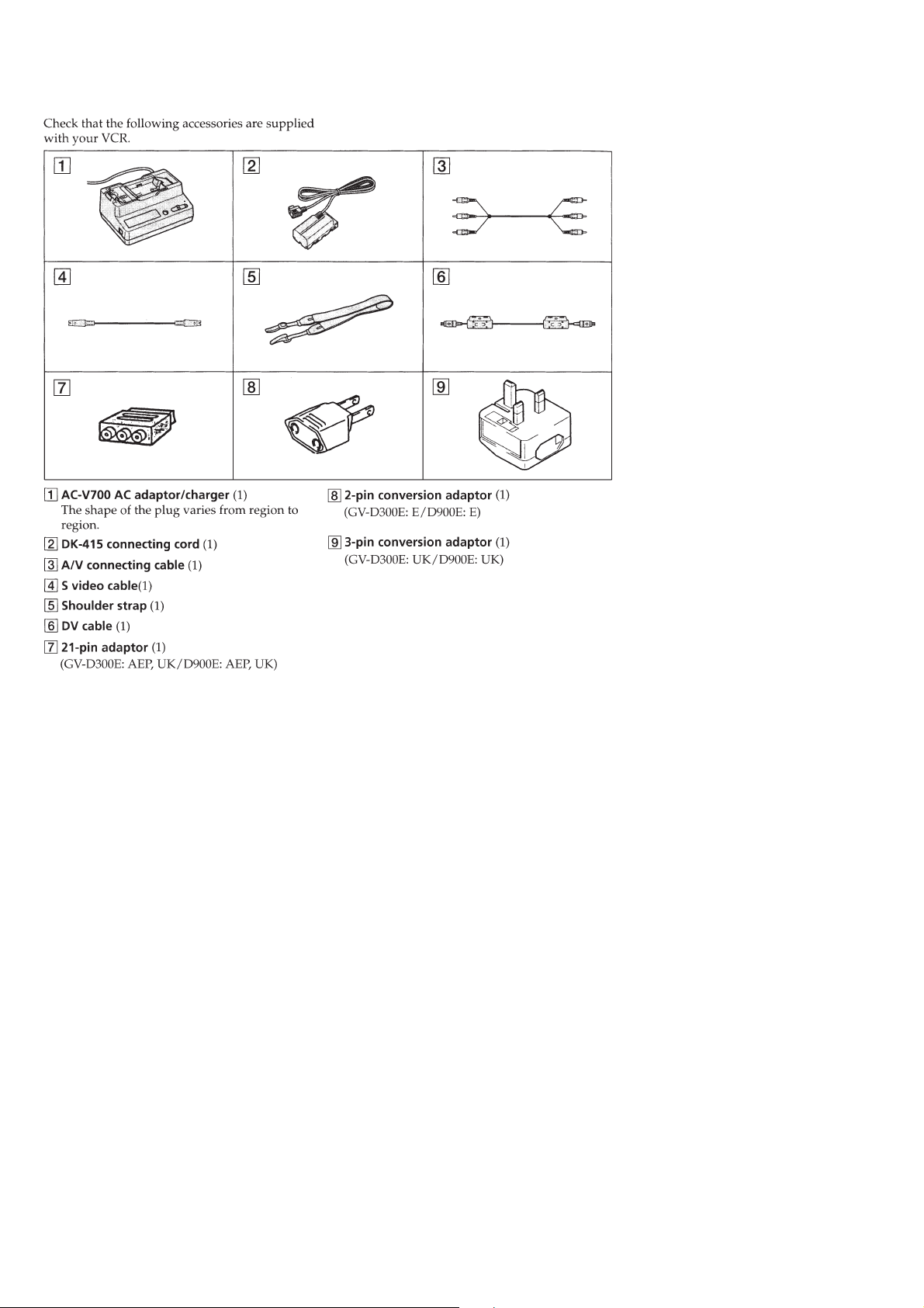
Supplied Accessories

— 3 —
TABLE OF CONTENTS
SERVICE NOTE
1. Power Supply During Repairs ............................................ 5
2. How to Take a Cassette Out When the Main Power Cannot
Be Turned ON (Forced Ejected) ......................................... 5
3. Warning Indicators .............................................................5
SELF-DIAGNOSIS FUNCTION
1. Self-Diagnosis Function ..................................................... 6
2. Self-Diagnosis Display....................................................... 6
3. Service Mode Display ........................................................ 6
3-1. Display Method .................................................................. 6
3-2. Switching of Backup No. ................................................... 6
3-3. End of Display.................................................................... 6
4. Self-Diagnosis Code Table ................................................. 7
1. GENERAL
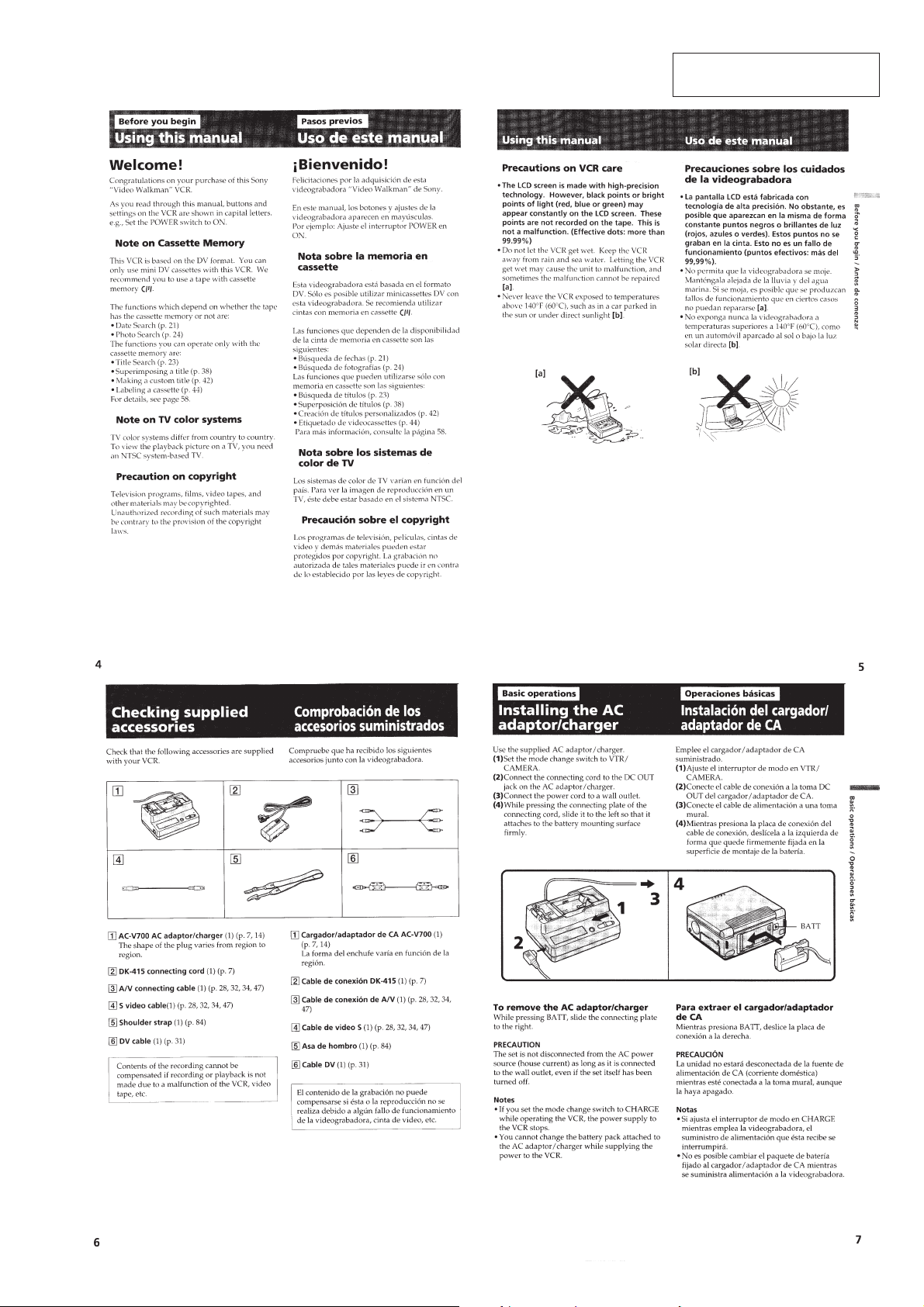
Before you begin
Using this manual ..................................................................1-1
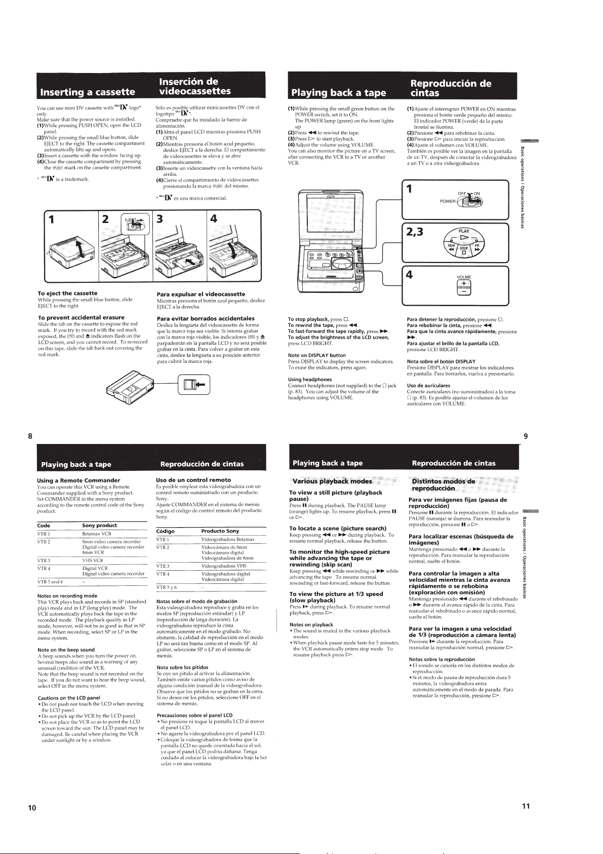
Basic operations
Installing the AC adaptor/charger ..........................................1-1
Inserting a cassette .................................................................1-2
Playing back a tape ................................................................1-2
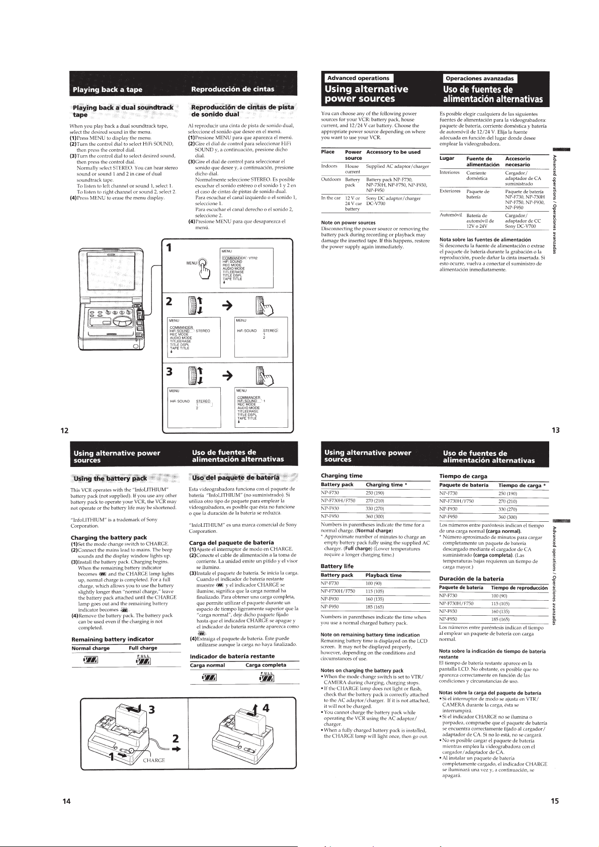
Advanced operations
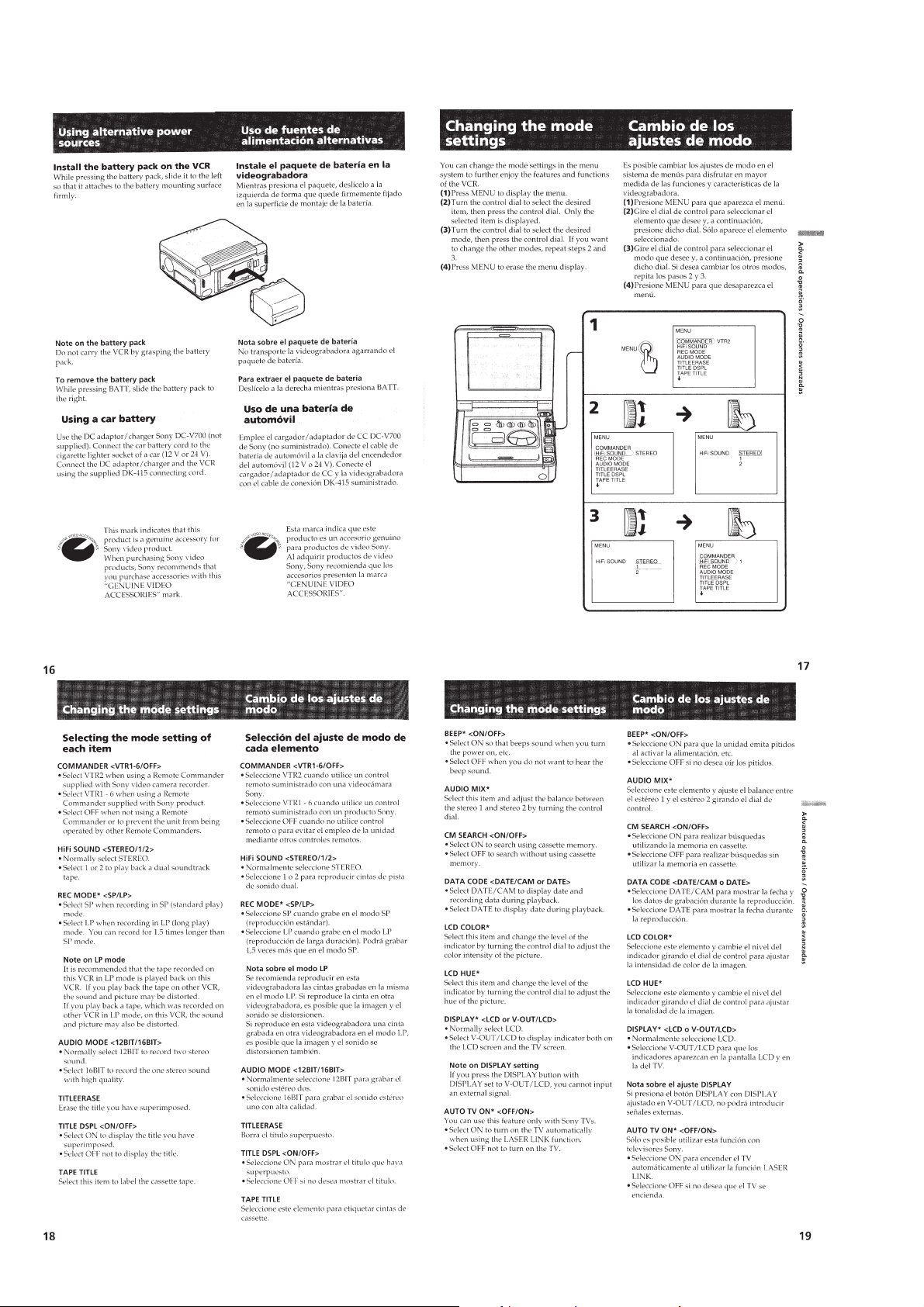
Using alternative power sources ............................................1-3
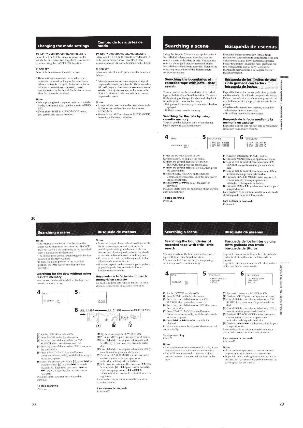
Changing the mode setting ....................................................1-4
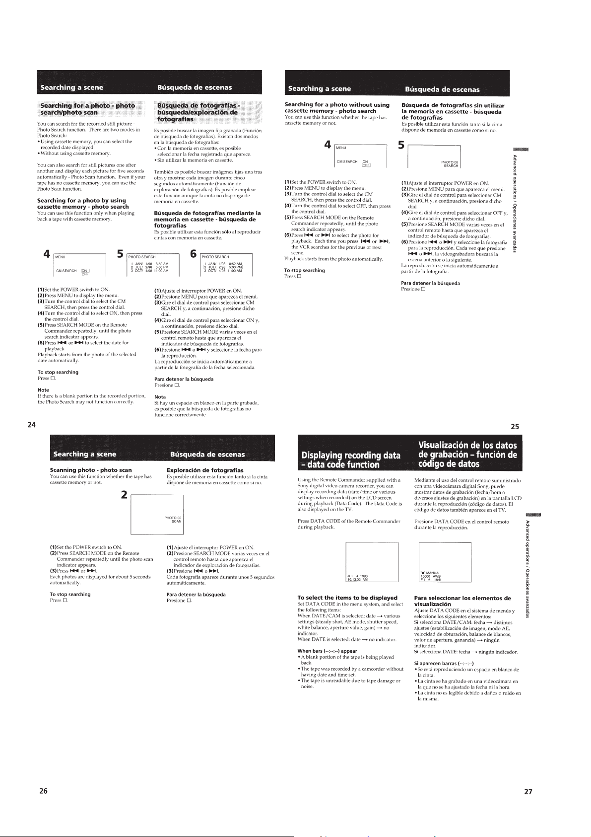
Searching a scene...................................................................1-5
Displaying recording data - data code function .....................1-6
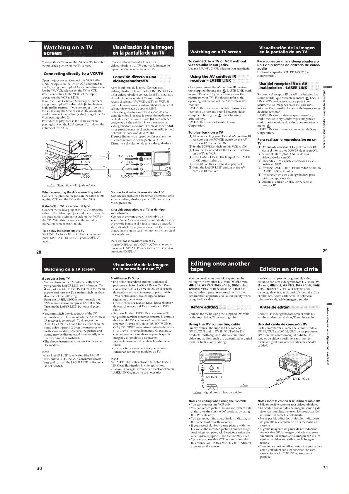
Watching on a TV screen .......................................................1-7
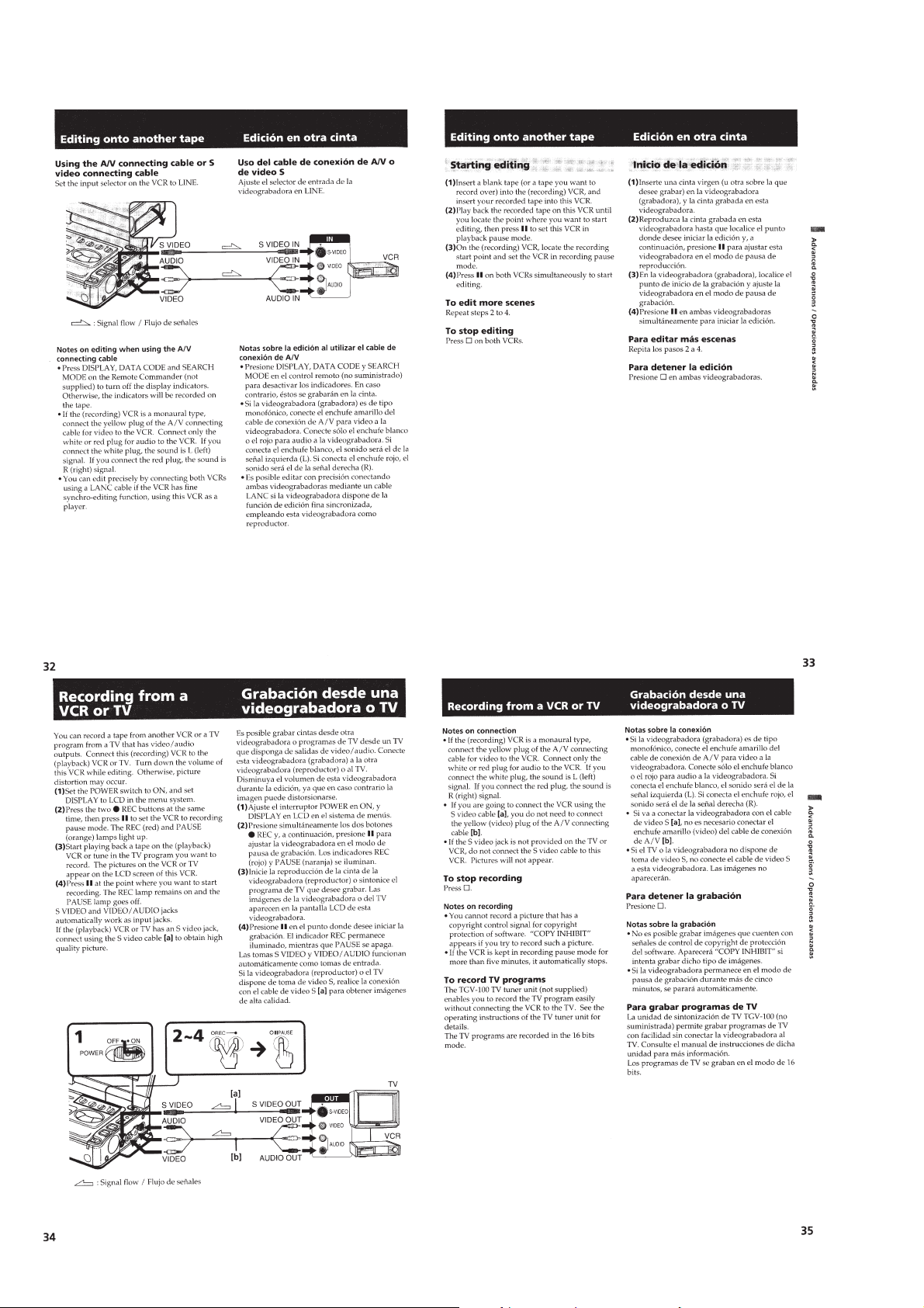
Editing onto another tape.......................................................1-7
Recording from a VCR or TV ...............................................1-8
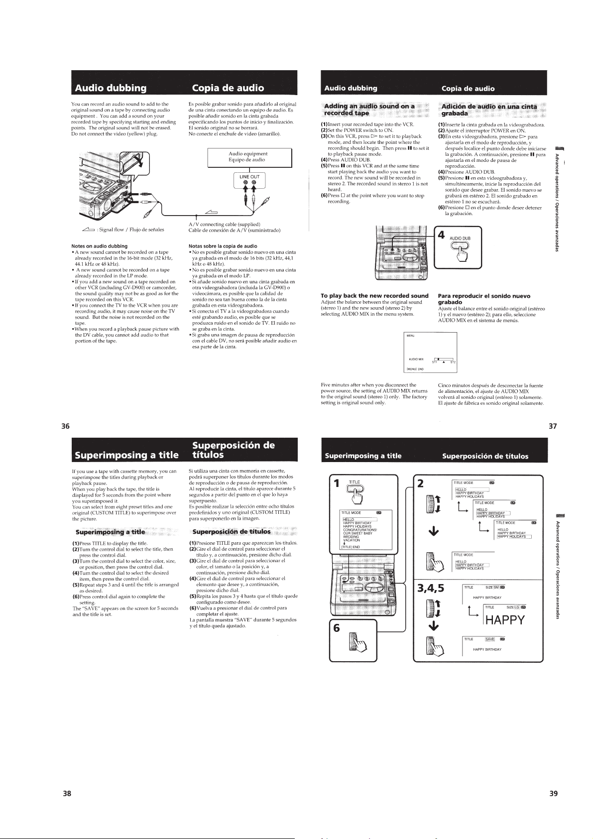
Audio dubbing .......................................................................1-9
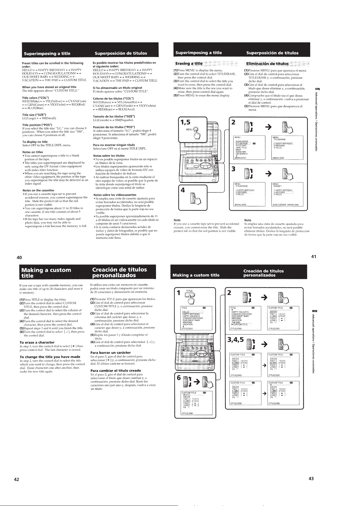
Superimposing a title .............................................................1-9
Making a custom title ..........................................................1-10
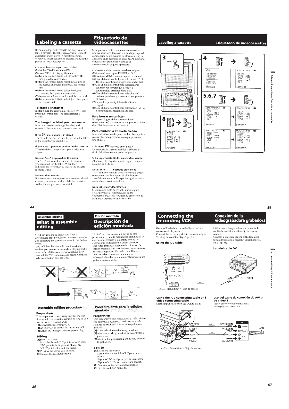
Labeling a cassette ...............................................................1-11
Assemble editing
What is assemble editing .....................................................1-11
Connecting the recording VCR............................................1-11
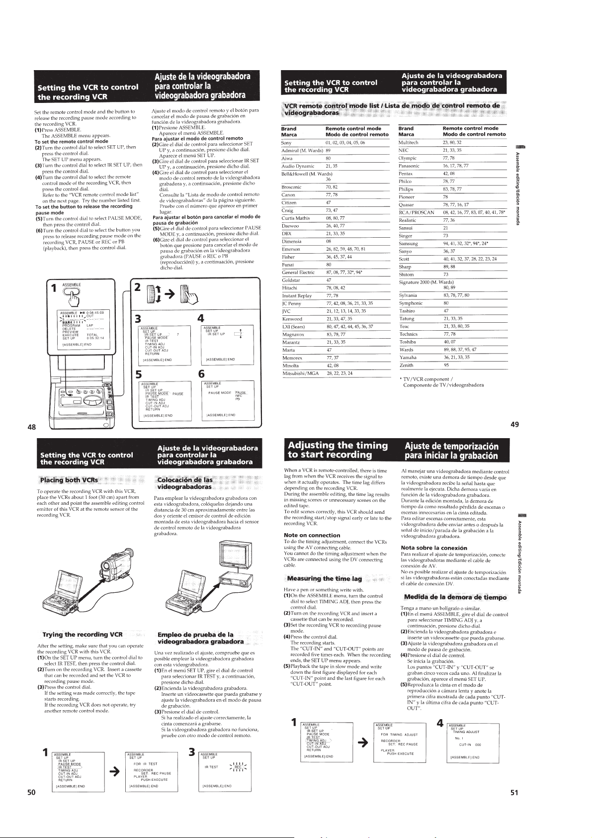
Setting the VCR to control the recording VCR ................... 1-12
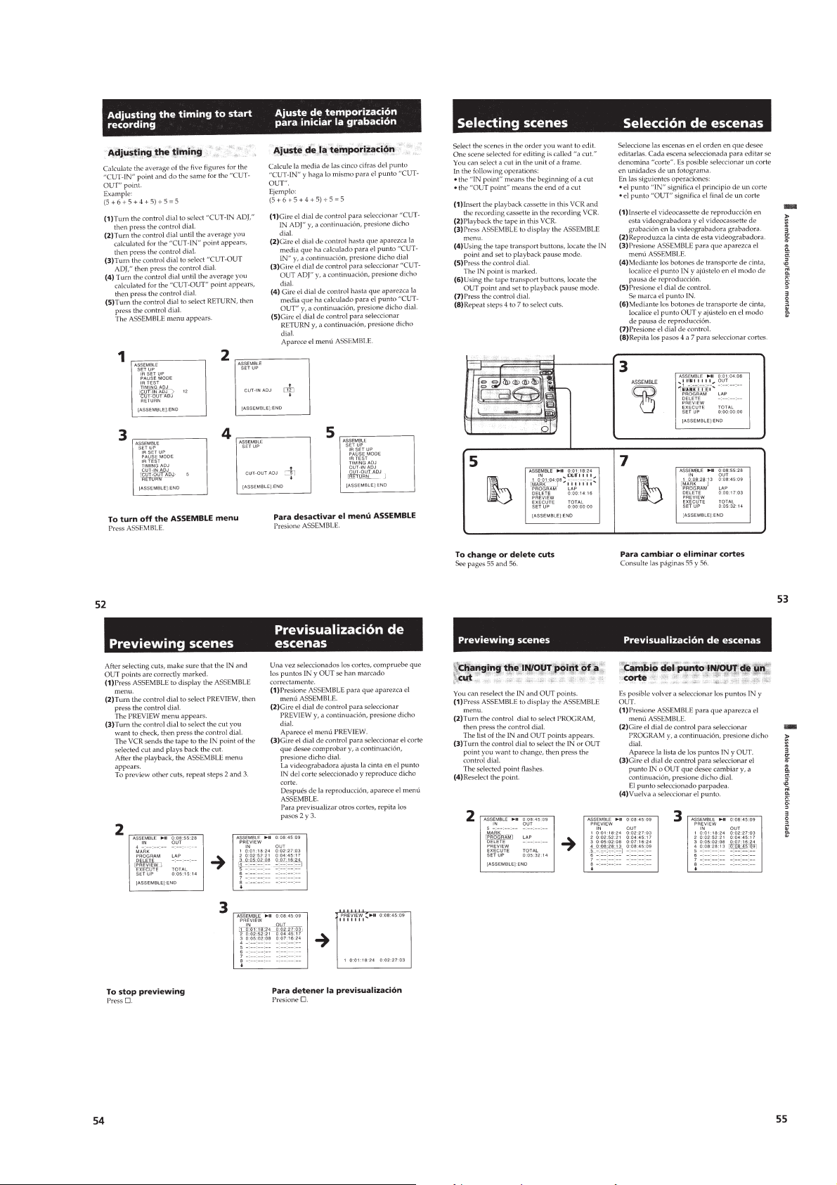
Adjusting the timing to start recording ................................1-12
Selecting scenes ...................................................................1-13
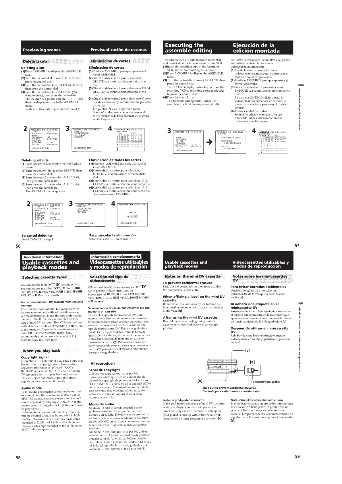
Previewing scenes................................................................1-13
Executing the assemble editing ........................................... 1-14
Additional information
Usable cassettes and playback modes..................................1-14
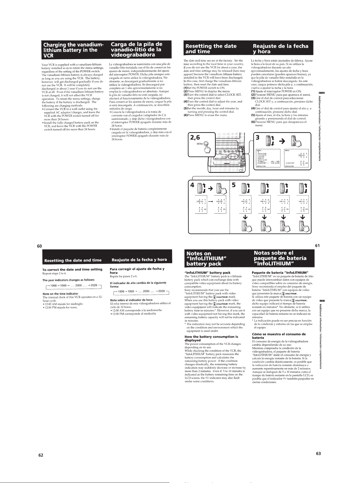
Charging the vanadium-lithium battery in the VCR ............1-15
Resetting the date and time..................................................1-15
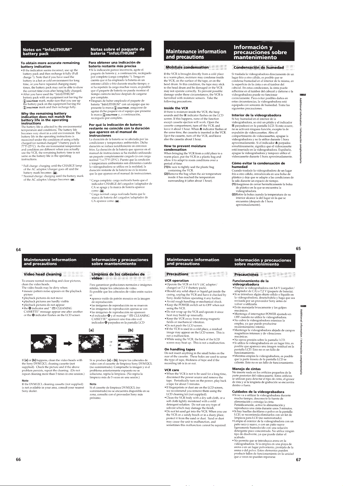
Notes on “InfoLITHIUM” battery pack ..............................1-15
Maintenance information and precautions...........................1-16
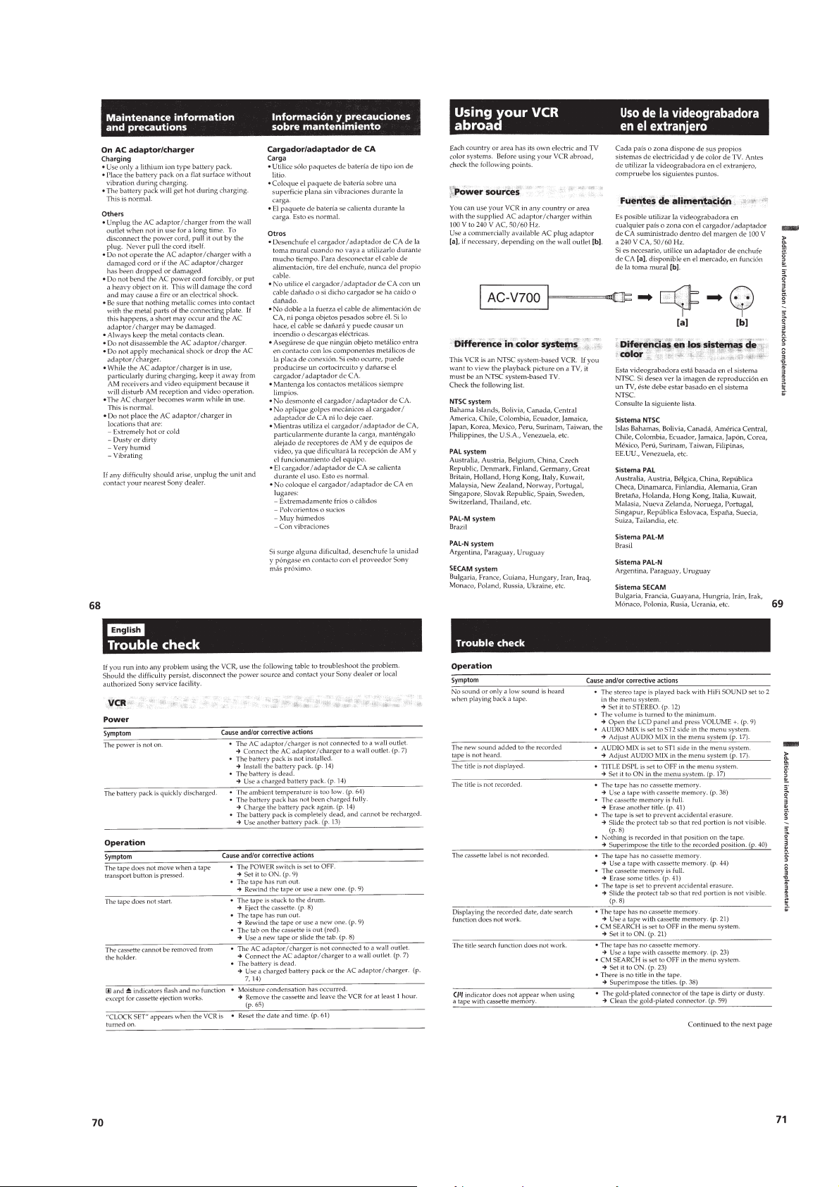
Using your VCR abroad ......................................................1-17
Trouble check ......................................................................1-17
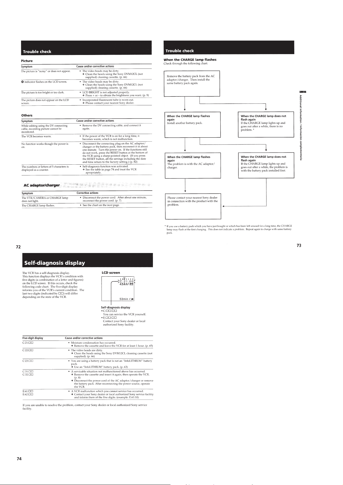
Self-diagnosis display ..........................................................1-18
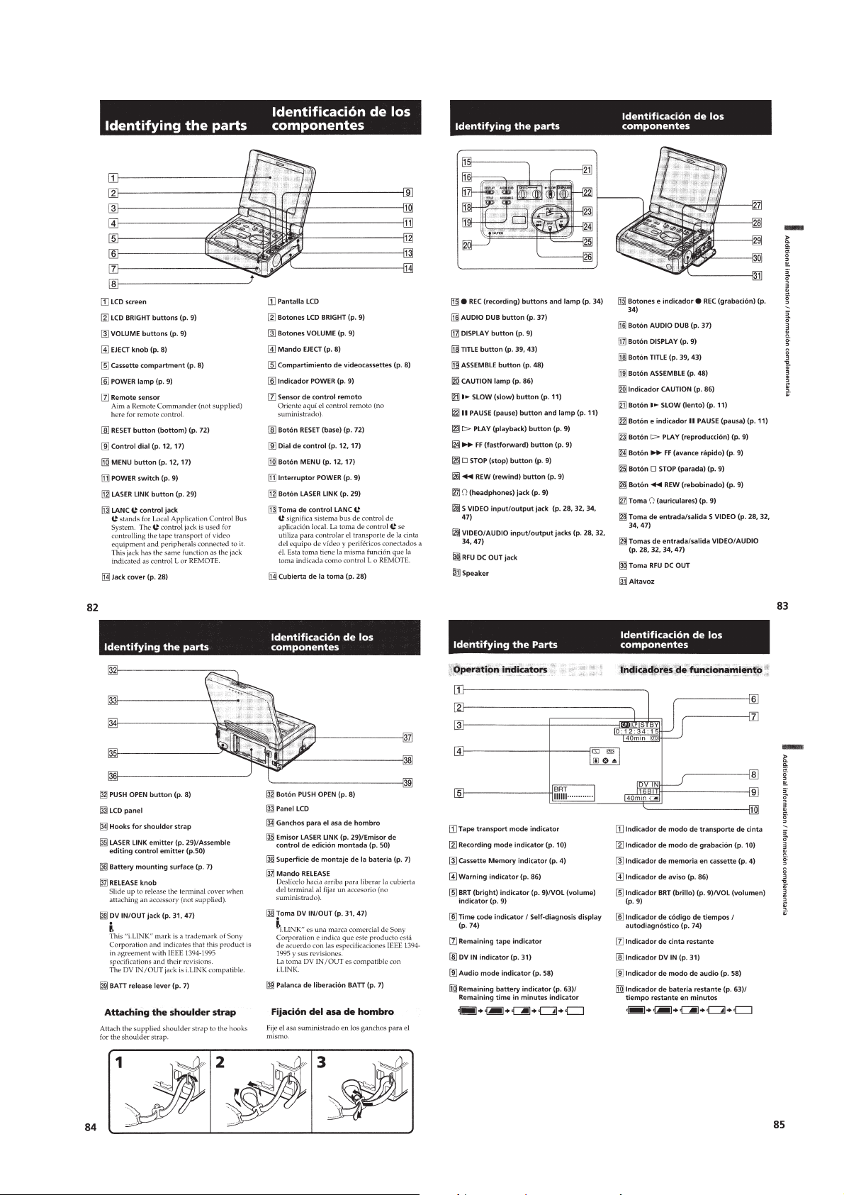
Identifying the parts .............................................................1-19
Warning indicators ...............................................................1-20
2. DISASSEMBLY
2-1. Cassette Lid Assembly .................................................... 2-1
2-2. Cabinet (Bottom) Assembly,
FP-571 (Lithium Battery) ................................................2-2
2-3. MD Block Assembly,
Battery Panel Assembly...................................................2-2
2-4. CB-61, RJ-77 Boards ......................................................2-3
2-5. Control Switch Block (FK-71) ........................................2-3
2-6. MD Block ........................................................................2-4
2-7. Cabinet (R) Assembly .....................................................2-4
This section is extracted from
instruction manual. (GV-D900)
2-8. IR-29, IO-62 Boards........................................................2-4
2-9. EX-34 Board....................................................................2-5
2-10. Cabinet (Upper) Assembly ..............................................2-5
2-11. LCD Display Module (GV-D900/D900E) ......................2-5
2-12. Circuit Boards Location ..................................................2-6
3. BLOCK DIAGRAMS
3-1. Overall Block Diagram (1) ..............................................3-1
3-2. Overall Block Diagram (2) ..............................................3-4
3-3. Power Block Diagram .....................................................3-7
4. PRINTED WIRING BOARDS AND
SCHEMATIC DIAGRAMS
4-1. Frame Schematic Diagram ..............................................4-1
4-2. Printed Wiring Boards and
Schematic Diagrams........................................................4-5
• CB-61 (Chroma Process, SYNC SEP, SIG Interface,
RGB Decoder, Audio, Mode Control, DC-DC Converter)
Printed Wiring Board ......................................4-7
• CB-61 (Signal Processor)(1/10)
Schematic Diagram .......................................4-14
• CB-61 (Video Input)(2/10)
Schematic Diagram .......................................4-17
• CB-61 (Chroma Process)(3/10)
Schematic Diagram .......................................4-21
• CB-61 (SYNC SEP, EVR, SIG Interface)(4/10)
Schematic Diagram .......................................4-23
• CB-61 (RGB Decoder)(5/10)
Schematic Diagram .......................................4-26
• CB-61 (Audio 1)(6/10) Schematic Diagram .............. 4-29
• CB-61 (Audio 2)(7/10) Schematic Diagram .............. 4-32
• CB-61 (IR Block)(8/10) Schematic Diagram.............4-35
• IR-29 (IR Transmitter)
Printed Wiring Board and
Schematic Diagram .......................................4-37
• CB-61 (Mode Control)(9/10)
Schematic Diagram .......................................4-40
• CB-61 (DC-DC Converter)(10/10)
Schematic Diagram .......................................4-43
• RJ-77 (REC/PB Process, RF Interface, Blocking,
Mecha Con/Servo, Audio Signal Process, Mode Control)
Printed Wiring Board .................................... 4-47
• RJ-77 (REC/PB Processor)(1/9)
Schematic Diagram .......................................4-51
• RJ-77 (RF Interface)(2/9)
Schematic Diagram .......................................4-56
• RJ-77 (DV Signal Process)(3/9)
Schematic Diagram .......................................4-59
• RJ-77 (Blocking, DRAM)(4/9)
Schematic Diagram .......................................4-63
• RJ-77 (ECC, TBC, CHCD)(5/9)
Schematic Diagram .......................................4-67
• FP-242, FP-584 (Tape Sensors)
Flexible Boards ............................................. 4-70
• RJ-77 (Audio Signal Process)(6/9)
Schematic Diagram .......................................4-72
• RJ-77 (Mecha Con/Servo)(7/9)
Schematic Diagram .......................................4-75
• Rj-77 (Audio Display)(8/9)
Schematic Diagram .......................................4-78
• Rj-77 (Mode Control)(9/9)
Schematic Diagram .......................................4-81
• IO-62 (AV In/Out)
Printed Wiring Board .................................... 4-83
• IO-62 (AV In/Out, Customer Control)
Schematic Diagram .......................................4-85

— 4 —
• EX-34 (DC-AC Inverter)
Schematic Diagram .......................................4-89
• EX-34 (Multi Connector, Back Light Power)
Printed Wiring Board .................................... 4-93
• FK-71 (Control Switch Block) ...................................4-95
5. ADJUSTMENTS
5-1. Adjustment Preparations .................................................5-1
1-1. Preparations Before Adjustment......................................5-1
1-1-1.List of Service Tools ........................................................5-1
5-2. Mechanism Section Adjustment...................................... 5-2
2-1. Operating Without Cassette .............................................5-2
2-2. Tape Path Adjustment......................................................5-2
1. Preparations for Adjustment............................................ 5-2
5-3. Electrical Adjustments.....................................................5-3
3-1. Preparations Before Adjustments ....................................5-3
3-1-1.Equipment Required ........................................................5-3
3-1-2.Precautions on Adjusting.................................................5-4
3-1-3.Adjusting Connectors ......................................................5-4
3-1-4.Connecting the Equipment ..............................................5-5
3-1-5.Checking the Input Signals..............................................5-6
3-1-7.Input/Output Level and Impedance .................................5-6
3-1-6.Alignment Tape ...............................................................5-6
3-2. Initialization of D, C Page Data ......................................5-7
1. Initializing the D Page Data ............................................5-7
2. Modification of D Page Data...........................................5-7
3. D Page Table.................................................................... 5-7
4. Initializing the C Page Data.............................................5-9
5. Modification of C Page Data...........................................5-9
6. C Page Table ....................................................................5-9
3-3. System Control System Adjustment..............................5-11
1. Battery End Adjustment (CB-61 Board) .......................5-11
3-4. Servo System Adjustments ............................................5-12
1. T Reel FG Duty Adjustment (RJ-77 Board)..................5-12
2. Switching Position Adjustment (RJ-77 Board) .............5-12
3-5. Video System Adjustments............................................5-13
3-5-1.RF Block Adjustments...................................................5-13
1. Recording Current Adjustment (RJ-77 Board)..............5-13
2. PLL F
0 Adjustment (RJ-77 Board) ................................5-13
3. CLK DELAY Adjustment (RJ-77 Board) .....................5-14
4. AGC Center Level Adjustment (RJ-77 Board)..............5-14
5. AEQ Adjustment (RJ-77 Board) ................................... 5-15
6. PLL Capture Range Adjustment (RJ-77 Board)............ 5-15
3-5-2. Clock Adjustments........................................................5-16
1. IC1900 27MHz XTAL F0 Adjustment (RJ-77 Board)...5-16
2. IC1900 VCO Operation Check (RJ-77 Board).............. 5-16
3. IC6101 41.85MHz VCO Operation Check
(RJ-77 Board) ................................................................5-16
3-5-3. Base Band Block Adjustments......................................5-17
1. NPS PLL Adjustment (CB-61 Board)...........................5-17
2. NPS Y Level Adjustment (CB-61 Board)...................... 5-17
3. VIDEO Output Y Level Adjustment (CB-61 Board) ....5-18
4. S VIDEO Output Y Level Adjustment
(CB-61 Board) ...............................................................5-18
5. AGC Adjustment (CB-61 Board) ..................................5-19
6. NPS B-Y Level Adjustment (CB-61 Board) .................5-19
7. NPS R-Y Level Adjustment For PAL Model
(CB-61 Board) ...............................................................5-20
8. VIDEO Output Burst Level Adjustment
(CB-61 Board) ...............................................................5-20
9. NPS R-Y Level Adjustment For NTSC Model
(CB-61 Board) ...............................................................5-20
10. S VIDEO Output Chroma Level Adjustment
(CB-61 Board) ...............................................................5-21
11. AFC TC Adjustment (CB-61 Board).............................5-21
12. AFC F0 Adjustment (CB-61 Board) ..............................5-22
13. Decoder APC Adjustment (CB-61 Board) ....................5-22
14. Decoder ACC Adjustment (CB-61 Board) ....................5-22
15. Decoder HUE Adjustment (CB-61 Board)....................5-23
16. Y AD Clamp Adjustment (CB-61 Board) .....................5-23
17. CR AD Clamp Adjustment (CB-61 Board) ...................5-24
18. CB AD Clamp Adjustment (CB-61 Board) ...................5-24
19. Y AD Level Adjustment (CB-61 Board) .......................5-25
20. CR AD Adjustment (CB-61 Board)...............................5-25
21. CB AD Level Adjustment (CB-61 Board).....................5-26
3-5-4.BIST Check ...................................................................5-27
1. Playback System Check ................................................5-27
2. Recording System Check ..............................................5-28
3-6. IR Transmitter Adjustments...........................................5-29
1. IR Video Carrier Frequency Adjustment
(CB-61 Board) ..............................................................5-29
2. IR Video Deviation Adjustment (CB-61 Board) ...........5-29
3. IR Audio Deviation Adjustment (CB-61 Board) ...........5-30
3-7. Audio System Adjustments ...........................................5-31
1. Playback Level Check ...................................................5-31
2. Overall Level Characteristics Check .............................5-31
3. Overall Separation Check.............................................. 5-31
4. Overall Noise Level Check............................................5-32
3-8. LCD System Adjustment (GV-D900/D900E) ...............5-33
1. LCD Initial Data Input ..................................................5-33
2. PANEL –19V Adjustment (CB-61 Board) ....................5-34
3. Horizontal Position Adjustment (CB-61 Board) ...........5-34
4. Bright Adjustment (CB-61 Board) ................................5-35
5. Contrast Adjustment (CB-61 Board).............................5-35
6. Color Adjustment for NTSC Model (CB-61 Board).....5-36
7. HUE Adjustment for NTSC Model (CB-61 Board)......5-36
8. Burst Cleaning Adjustment For PAL Model
(CB-61 Board) ...............................................................5-37
9. Color Adjustment For PAL Model (CB-61 Board) .......5-37
10. V-COM Adjustment (CB-61 Board) .............................5-38
11. White Balance Adjustment (CB-61 Board)...................5-38
5-4. Service Mode.................................................................5-39
4-1. Adjustment Remote Commander .................................. 5-39
1. Using the Adjustment Remote Commander..................5-39
2. Precautions Upon Using the
Adjustment Remote Commander .................................. 5-39
4-2. Data Process ..................................................................5-40
4-3. Service Mode.................................................................5-41
1. Setting the Test Mode ....................................................5-41
2. Emergence Memory Address ........................................5-41
2-1. EMG Code (Emergency Code) .....................................5-41
2-2. MSW Code ....................................................................5-42
3. Bit Value Discrimination ...............................................5-43
4. Switch Check (1) ...........................................................5-43
5. Switch Check (2) ...........................................................5-44
6. Record of Use Check..................................................... 5-44
6. REPAIR PARTS LIST
6-1. Exploded Vie ws ...............................................................6-1
6-1-1.Cabinet Assembly ............................................................6-1
6-1-2.LCD Window Cabinet, Cabinet (Upper) Assembly ........6-2
6-1-3.Mechanism Deck Assembly ............................................6-3
6-1-4.Cassette Compartment and Drum Assembly...................6-4
6-1-5.LS Chassis Block Section................................................6-5
6-1-6.Mechanism Chassis Block Section-1 ..............................6-6
6-1-7.Mechanism Chassis Block Section-2 ..............................6-7
6-2. Electrical Parts List .........................................................6-8
— 5 —
SERVICE NOTE
1. POWER SUPPLY DURING REPAIRS
In this unit, about 5 seconds after power is supplied (8.4V) to the
battery terminal using the service power cord (J-6082-223-A), the
power is shut off so that the unit cannot operate.
This following two methods are av ailable to prev ent this. Take note
of which to use during repairs.
Method 1.
Connect the servicing remote commander RM-95 (J-6082-053-B)
to the LANC jack, and set the remote commander switch to the
“ADJ” side.
Method 2.
Press the following battery switch using adhesive tape, etc.
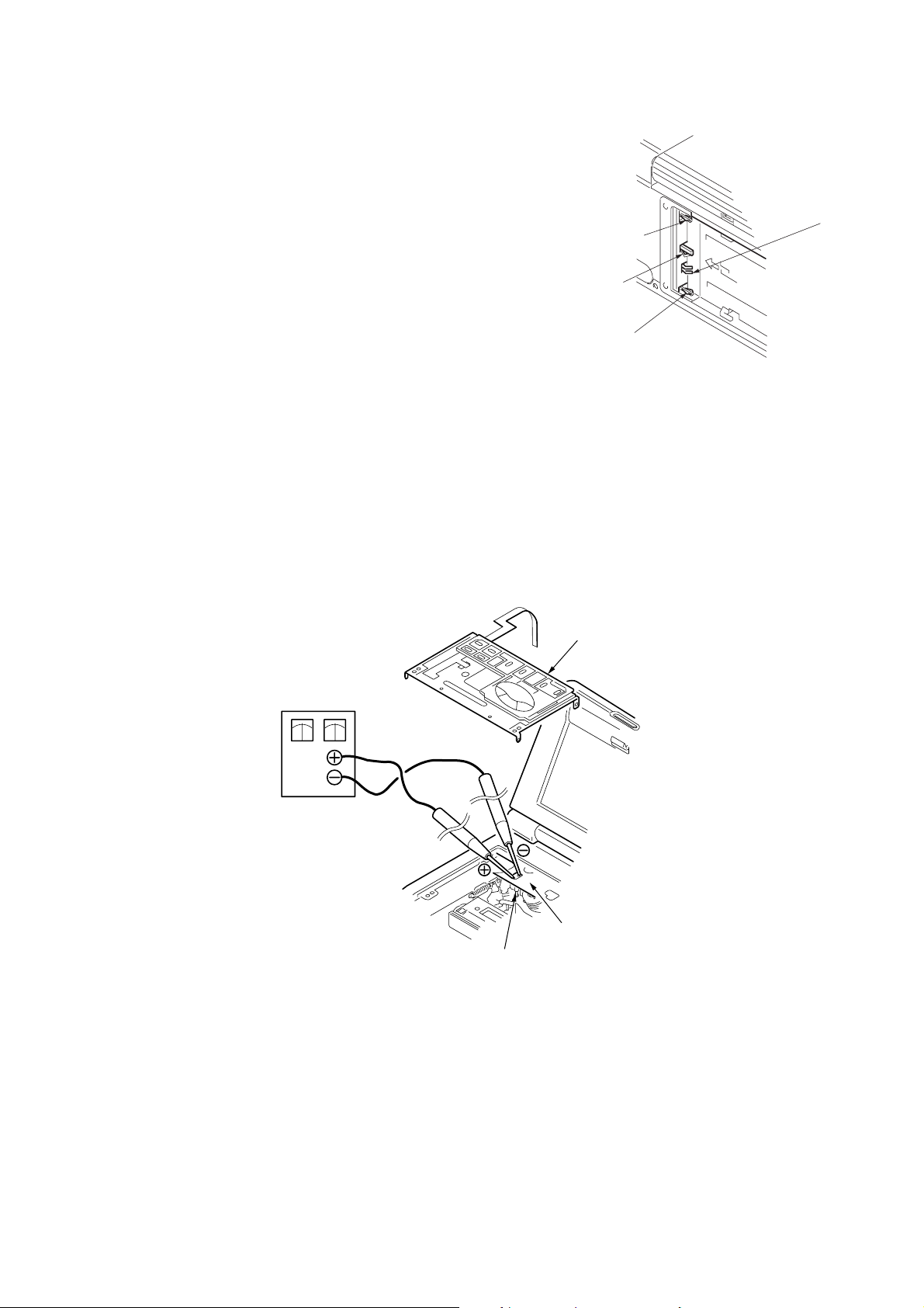
2. HOW TO TAKE A CASSETTE OUT WHEN THE MAIN POWER
CANNOT BE TURNED ON (FORCED EJECTED)
Procedure:
1. Remove the cassette lid referring to the section “2. DISASSEMBLY, 2-1”.
2. Remove the operation switch block (FK-71 board) referring to the section “2. DISASSEMBLY, 2-5”.
3. Remove the CB-61 board referring to section “2. DISASSEMBLY, 2-4”, and remove the FP-586 flexible board from CN3140 (4P) on
the RJ-77 board.
4. Apply +4.5 V from the regulated power supply to the loading motor terminal as shown below and remove the cassette.
CAUTION: Be careful not contact with the lid frame assembly when applying +4.5 V.
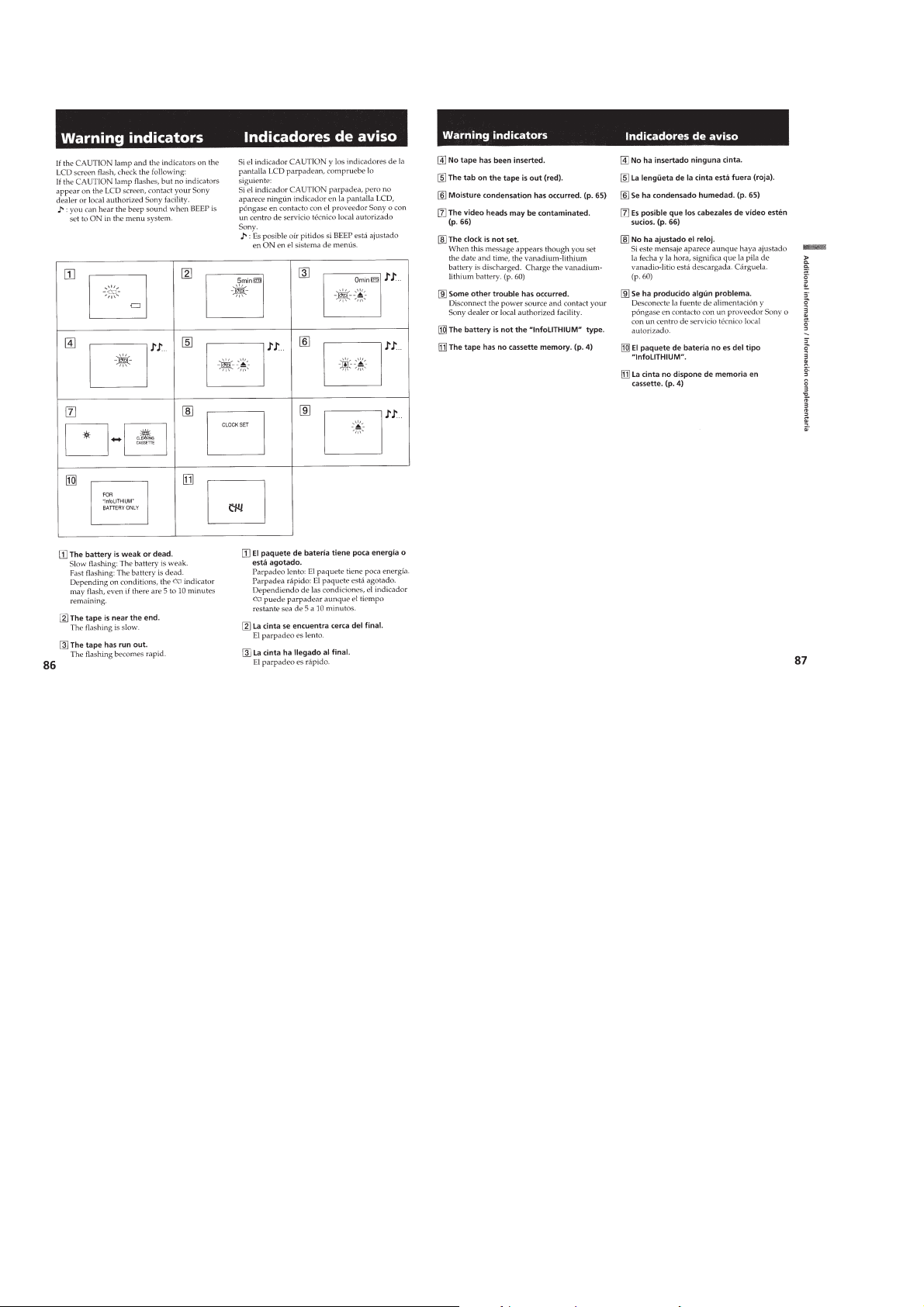
3. WARNING INDICATORS
If the CAUTION lamp flashes, b ut no indicators appear on the LCD screen or on the monitor TV screen, it means tha t an error occurs either
in the fan motor or in the fan motor drive circuit. Refer to the schematic diagram on page 4-43 for repair.
Regulated power supply
4.5V
GND
Control switch bloc
k
Loading motor
Lid frame assembly
Battery switch
Battery sig terminal
Battery terminal
‘
Battery terminal
’
— 6 —
SELF-DIAGNOSIS FUNCTION
1. SELF-DIAGNOSIS FUNCTION
When problems occur while the unit is operating, the self-diagnosis
function starts working, and displays on the LCD screen or monitor
TV (Note) what to do. This function consists of two display; self-
diagnosis display and service mode display.
Details of the self-diagnosis functions are provided in the Instruction
manual.
Note: The “self-diagnosis displa y” data will be backed up by the coin-type lithium battery of FP-571 flexible board. When this coin-type lithium ba ttery
is removed, the “self-diagnosis display” data will be lost by initialization.
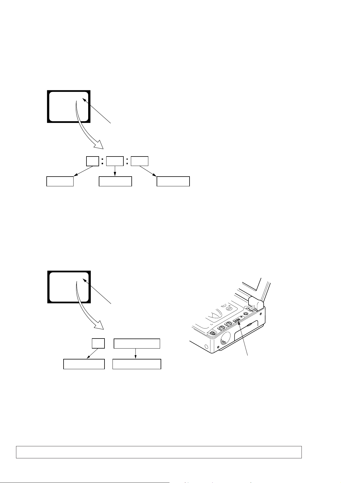
2. SELF-DIAGNOSIS DISPLAY
When problems occur while the unit is operating, the counter of the
viewfinder shows a 4-digit display consisting of an alphabet and
numbers, which blinks at 3.2 Hz. This 5-character display indicates
the “repaired by:”, “block” in which the problem occurred, and
“detailed code” of the problem.
Note: Set the DISPLAY in the menu system to V-OUT/LCD only for the
model with LCD screen, and press the DISPLAY button.
3. SER VICE MODE DISPLAY
The service mode display shows up to six self-diagnosis codes shown in the past.
3-1. Display Method
While pressing the “STOP” key, set the switch from OFF to ON, and continue pressing the “STOP” key for 10 seconds continuously. The
service mode will be displayed, and the counter will show the backup No. and the 5-character self-diagnosis codes.
3-2. Switching of Backup No.
By rotating the control dial, past self-diagnosis codes will be shown in order. The backup No. in the [] indicates the order in which the
problem occurred. (If the number of problems which occurred is less than 6, only the number of problems which occurred will be shown.)
[1] : Occurred first time [4] : Occurred fourth time
[2] : Occurred second time [5] : Occurred fifth time
[3] : Occurred third time [6] : Occurred the last time
3-3. End of Display
Turning OFF the power supply will end the service mode display.
1 1
3 1C
Repaired by:
Refer to page 7.
Self-diagnosis Code Table.
Indicates the appropriate
step to be taken.
E.g.
31 ....Reload the tape.
32 ....Tur n o n power again.
Block
Detailed Code
Blinks at 3.2Hz
C : Corrected by customer
H : Corrected by dealer
E : Corrected by service
engineer
LCD screen or monitor TV
C : 3 1 : 1 1
Order of previous errors
Backup No.
self-diagnosis codes
C : 3 1 : 1 1
[3]
Lights up
LCD screen or monitor TV
[3] C : 3 1 : 1 1
Control dial
— 7 —
4. SELF-DIAGNOSIS CODE TABLE
C
C
C
C
C
C
C
C
C
C
C
C
C
C
C
C
C
C
C
C
C
C
C
Block
Function
21
22
23
31
31
31
31
31
31
31
31
31
31
31
31
32
32
32
32
32
32
32
32
Detailed
Code
00
00
00
10
11
20
21
22
23
24
30
40
42
10
11
20
21
22
23
24
30
40
42
Symptom/State
Condensation.
Video head is dirty.
Non-standard battery is used.
LOAD direction. Loading does not
complete within specified time
UNLOAD direction. Loading does not
complete within specified time
T reel side tape slacking when unloading
.
Winding S reel fault when counting the
rest of tape.
T reel fault.
S reel fault.
T reel fault.
FG fault when starting capstan.
FG fault when starting drum.
FG fault during normal drum operations.
LOAD direction loading motor time-
out.
UNLOAD direction loading motor
time-out.
T reel side tape slacking when
unloading.
Winding S reel fault when counting the
rest of tape.
T reel fault.
S reel fault.
T reel fault.
FG fault when starting capstan.
FG fault when starting drum
FG fault during normal drum
operations
Self-diagnosis Code
Repaired by:
Correction
Remove the cassette, and insert it again after one hour.
Clean with the optional cleaning cassette.
Use the info LITHIUM battery.
Load the tape again, and perform operations from the beginning.
Load the tape again, and perform operations from the beginning.
Load the tape again, and perform operations from the beginning.
Load the tape again, and perform operations from the beginning.
Load the tape again, and perform operations from the beginning.
Load the tape again, and perform operations from the beginning.
Load the tape again, and perform operations from the beginning.
Load the tape again, and perform operations from the beginning.
Load the tape again, and perform operations from the beginning.
Load the tape again, and perform operations from the beginning.
Remove the battery or power cable, connect, and perform
operations from the beginning.
Remove the battery or power cable, connect, and perform
operations from the beginning.
Remove the battery or power cable, connect, and perform
operations from the beginning.
Remove the battery or power cable, connect, and perform
operations from the beginning.
Remove the battery or power cable, connect, and perform
operations from the beginning.
Remove the battery or power cable, connect, and perform
operations from the beginning.
Remove the battery or power cable, connect, and perform
operations from the beginning.
Remove the battery or power cable, connect, and perform
operations from the beginning.
Remove the battery or power cable, connect, and perform
operations from the beginning.
Remove the battery or power cable, connect, and perform
operations from the beginning.
1-1
GV-D300/D300E/D900/D900E
SECTION 1
GENERAL
This section is extracted from
instruction manual. (GV-D900)
1-2
1-3
1-4
1-5
1-6
1-7
1-8
1-9
1-10
1-11
1-12
1-13
1-14
1-15
1-16
1-17
1-18
1-19
1-20E
2-1
GV-D300/D300E/D900/D900E
SECTION 2
DISASSEMBLY
NOTE: Follow the disassembly procedure in the numerical order given.
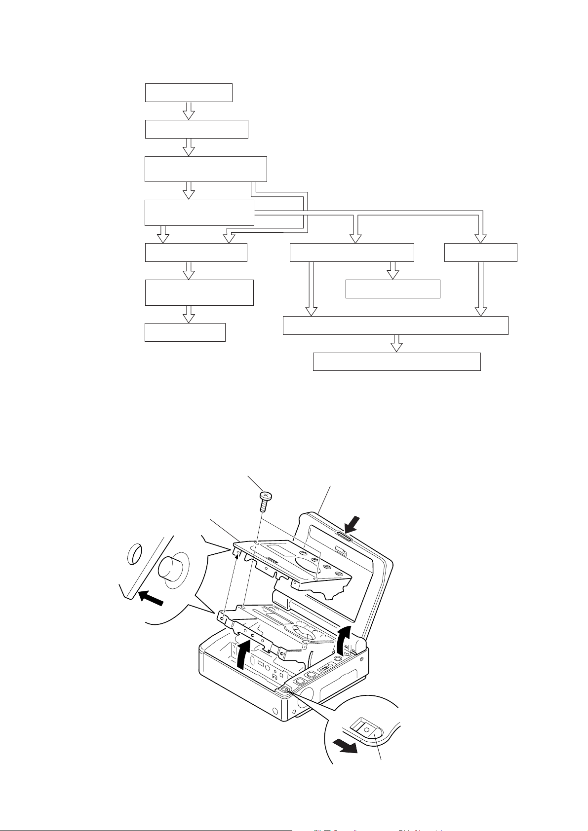
2-1. CASSETTE LID ASSEMBLY
1
Open the LCD window cabinet
assembly in the direction of the
arrow
A
. (only D900/D900E)
A
2
Two screws (M2)
4
Remove the cassette
lid assembly
3
Press the cassette EJECT
knob to open the cassette
compartment.
Push here.
Video WALKMAN
2-1. Cassette lid assembly
2-2. Cabinet (bottom) assembly
FP-571 (lithium battery)
2-3. MD block assembly
Battery panel assembly
2-4. CB-61, RJ-77 boards
2-5. Control switch block
(FK-71)
2-6. MD block
2-7. Cabinet (R) assembly
2-10. Cabinet (upper) assembly
2-11. LCD display module (GV-D900/D900E)
2-8. IR-29, IO-62 boards
2-9. EX-34 board
2-2
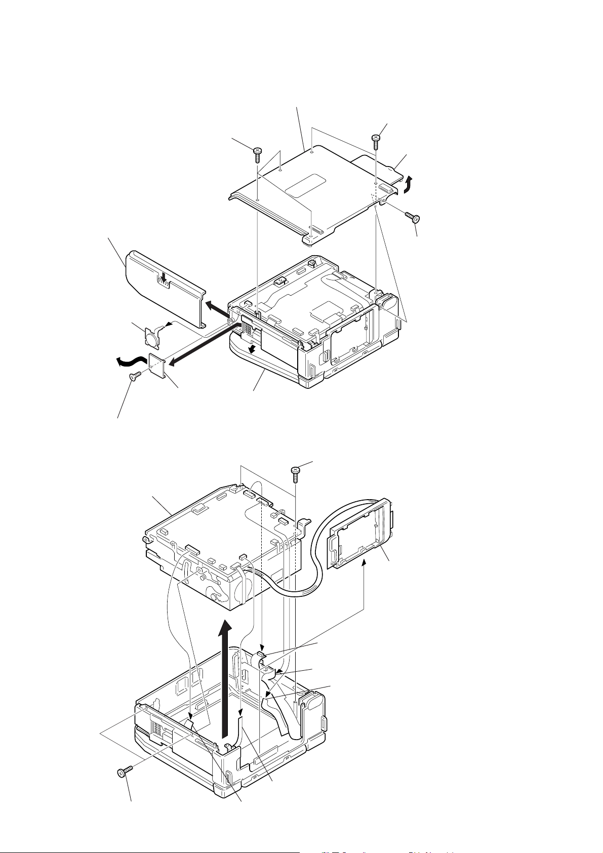
2-2. CABINET (BOTTOM) ASSEMBLY, FP-571(LITHIUM BATTERY)
2-3. MD BLOCK ASSEMBLY, BATTERY PANEL ASSEMBLY
CB-61
BO
ARD
3
Three screws (M2)
3
Two screws (M2)
3
Screw (M2
)
B
4
Open the Jack lid in the direction of the
arrow
B
and remove the cabinet (bottom)
assembly.
A
2
Press the release button to remove
the cabinet (bottom) assembly in the
direction of the arrow
A
.
5
Tapping screw (+K2
×
5)
6
Remove the lithium
lid in the direction
of the arrow
C
.
7
FP-571 flexible board
CB-61 board CN9926 4P
1
Open the LCD panel a little.
C
Jack lid
CB-61
BOARD
8
Remove the MD block assembly.
7
Two screws (M2)
6
Remove the battery
panel assembly.
5
FP-598 flexible board
3
FP-569 flexible board
4
FP-572 flexible board
2
FP-602 flexible board
1
FP-570 flexible board
CB-61 board CN9931 40P
7
Two screws (M2 black)
2-3
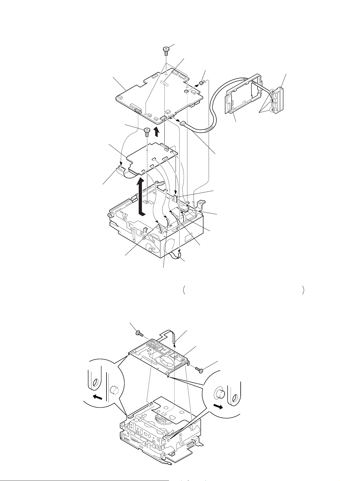
2-4. CB-61, RJ-77 BOARDS
2-5. CONTROL SWITCH BLOCK (FK-71)
CB-61
BOARD
RJ-77
BOARD
3
Three screws (M2)
4
Remove the CB-61 board.
8
Screw (M2)
1
DC fan cable
3
7
Remove the battery
terminal.
Board to board connector
Battery panel
Claws
2
6
Battery panel assembly cable
CN3900 5P
1
2
Control switch block (FK-71) CN9927 10P
0
Flexible board
CN2708 10P
(from video head)
9
FP586 flexible board
CN3104 4P
(from loading motor)
!¡
Flexible board
CN3103 11P (from drum motor)
!™
FP-538 flexible board
CN3102 17P (from S reel/ T reel)
!£
Flexible board
CN3101 6P (from the mode switch)
!¢
CN3100 18P (from capstan motor)
A
5
FP-599 flexible board
CN9930 50P
!∞
Remove the RJ-77 board
in the direction of the arrow
A
.
The numbers in square
`
show the order of disassembly
when removing the battery terminal board only.
2
Screw (M1.4
×
2.5)
1
Remove the flexible board from the CB-61 board CN9927 (10P).
3
Remove the Control switch block (FK-71)
2
Screw (M1.4
×
2.5)
 Loading...