


3-861-575-15 (1)
Trinitron Color
Graphic Display
Operating Instructions |
|
|
EN |
||
|
|
|
|||
|
|
|
|
|
|
Mode d’emploi |
F |
||||
|
|
|
|
|
|
Manual de instrucciones |
ES |
||||
|
|
|
|
|
|
|
|
|
|
|
C |
GDM-400PS
GDM-500PS
© 1997 by Sony Corporation
Owner’s Record
The model and serial numbers are located at the rear of the unit. Record the serial number in the space provided below. Refer to these numbers whenever you call upon your dealer regarding this product.
Model No. |
|
Serial No. |
WARNING
To prevent fire or shock hazard, do not expose the unit to rain or moisture.
Dangerously high voltages are present inside the unit. Do not open the cabinet. Refer servicing to qualified personnel only.
FCC Notice
This equipment has been tested and found to comply with the limits for a Class B digital device, pursuant to Part 15 of the FCC Rules. These limits are designed to provide reasonable protection against harmful interference in a residential installation. This equipment generates, uses, and can radiate radio frequency energy and, if not installed and used in accordance with the instructions, may cause harmful interference to radio communications. However, there is no guarantee that interference will not occur in a particular installation. If this equipment does cause harmful interference to radio or television reception, which can be determined by turning the equipment off and on, the user is encouraged to try to correct the interference by one or more of the following measures:
–Reorient or relocate the receiving antenna.
–Increase the separation between the equipment and receiver.
–Connect the equipment into an outlet on a circuit different from that to which the receiver is connected.
–Consult the dealer or an experienced radio/TV technician for help. You are cautioned that any changes or modifications not expressly approved in this manual could void your authority to operate this equipment.
INFORMATION
This product complies with Swedish National Council for Metrology (MPR) standards issued in December 1990 (MPR II) for very low frequency (VLF) and extremely low frequency (ELF).
INFORMATION
Ce produit est conforme aux normes du Swedish National Council for Metrology de décembre 1990 (MPR II) en ce qui concerne les fréquences très basses (VLF) et extrêmement basses (ELF).
Hinweis
Dieses Gerät erfüllt bezüglich tieffrequenter (very low frequency) und tiefstfrequenter (extremely low frequency) Strahlung die Vorschriften des „Swedish National Council for Metrology (MPR)“ vom Dezember 1990 (MPR II).
INFORMACIÓN
Este producto cumple las normas del Consejo Nacional Sueco para Metrología (MPR) emitidas en diciembre de 1990 (MPR II) para frecuencias muy bajas (VLF) y frecuencias extremadamente bajas (ELF).
Hinweise
•Aus ergonomischen Gründen wird empfohlen, die Grundfarbe Blau nicht auf dunklem Untergrund zu verwenden (schlechte Erkennbarkeit, Augenbelastung bei zu geringem Zeichenkontrast).
•Aus ergonomischen Gründen (flimmern) sollten nur Darstellungen bei Vertikalfrequenzen ab 70 Hz (ohne Zeilensprung) verwendet werden.
•Die Konvergenz des Bildes kann sich auf Grund des Magnetfeldes am Ort der Aufstellung aus der korrekten Grundeinstellung verändern. Zur Korrektur empfiehlt es sich deshalb, die Regler an der Frontseite für Konvergenz so einzustellen, daß die getrennt sichtbaren Farblinien für Rot, Grün und Blau bei z.B. der Darstellung eines Buchstabens zur Deckung (Konvergenz) gelangen.
Siehe hierzu auch die Erklärungen zu Konvergenz.
NOTICE
This notice is applicable for USA/Canada only.
If shipped to USA/Canada, install only a UL LISTED/CSA LABELLED power supply cord meeting the following specifications:
SPECIFICATIONS
Plug Type |
|
|
|
Nema-Plug 5-15p |
||||
Cord |
|
|
|
Type SVT or SJT, minimum 3 × 18 AWG |
||||
Length |
|
|
|
Maximum 15 feet |
||||
Rating |
|
|
|
Minimum 7 A, 125 V |
||||
|
|
|
|
|
|
|
|
|
|
|
|
|
|
|
|
|
|
|
|
|
|
|
|
|
|
|
|
|
|
|
|
|
|
|
|
|
|
|
|
|
|
|
|
|
|
|
|
|
|
|
|
|
|
|
|
|
|
|
|
|
|
|
|
|
|
|
|
|
|
|
|
|
|
|
|
|
|
|
|
|
(GDM-400PS only)
This monitor complies with the
TCO‘95 guidelines.
(GDM-500PS only)
(V C C I B
(GDM-500PS only)
2

TABLE OF CONTENTS |
|
Getting Started |
|
Precautions ........................................................................................................................... |
4 |
Identifying Parts and Controls .......................................................................................... |
5 |
Setup ...................................................................................................................................... |
6 |
Automatically Adjusting the Size and Centering of the Picture................................... |
7 |
Selecting the On-screen Display Language ..................................................................... |
7 |
Selecting the Input Signal ................................................................................................... |
8 |
Customizing Your Monitor |
|
Adjusting the Picture Brightness and Contrast ............................................................... |
9 |
Introducing the On-screen Display System ..................................................................... |
9 |
Using the CENTER On-screen Display .......................................................................... |
10 |
Using the SIZE On-screen Display .................................................................................. |
10 |
Using the GEOM (Geometry) On-screen Display ......................................................... |
11 |
Using the ZOOM On-screen Display .............................................................................. |
12 |
Using the COLOR On-screen Display ............................................................................ |
12 |
Using the SCREEN On-screen Display ........................................................................... |
13 |
Using the OPTION On-screen Display ........................................................................... |
15 |
Using the LANG (Language) On-screen Display ......................................................... |
17 |
Resetting the Adjustments ............................................................................................... |
17 |
Technical Features |
|
Preset and User Modes ..................................................................................................... |
18 |
Power Saving Function ..................................................................................................... |
19 |
Damper Wires .................................................................................................................... |
19 |
Plug & Play ......................................................................................................................... |
19 |
Additional Information |
|
Warning Messages ............................................................................................................. |
20 |
Troubleshooting ................................................................................................................. |
20 |
Self-diagnosis Function ..................................................................................................... |
22 |
Specifications ...................................................................................................................... |
22 |
•Macintosh is a trademark licensed to Apple Computer, Inc., registered in the U.S.A. and other countries.
•Windows® and MS-DOS are registered trademarks of Microsoft Corporation in the United States and other countries.
•IBM PC/AT and VGA are registered trademarks of IBM Corporation of the U.S.A.
•VESA is a trademark of Video Electronics Standard Association.
•All other product names mentioned herein may be the trademarks or registered trademarks of their respective companies.
•Furthermore, “™” and “®" are not mentioned in each case in this manual.
EN
F
ES
C
3
Getting startedS
Precautions
Installation
•Prevent internal heat build-up by allowing adequate air circulation. Do not place the monitor on surfaces (rugs, blankets, etc.) or near materials (curtains, draperies) that may block the ventilation holes.
•Do not install the monitor near heat sources such as radiators or air ducts, or in a place subject to direct sunlight, excessive dust, mechanical vibration or shock.
•Do not place the monitor near equipment which generates magnetism, such as a transformer or high voltage power lines.
Maintenance
•Clean the cabinet, panel and controls with a soft cloth lightly moistened with a mild detergent solution. Do not use any type of abrasive pad, scouring powder or solvent, such as alcohol or benzine.
•Do not rub, touch, or tap the surface of the screen with sharp or abrasive items such as a ballpoint pen or screwdriver. This type of contact may result in a scratched picture tube.
•Clean the screen with a soft cloth. If you use a glass cleaning liquid, do not use any type of cleaner containing an anti-static solution or similar additive as this may scratch the screen’s coating.
Transportation
When you transport this monitor for repair or shipment, use the original carton and packing materials.
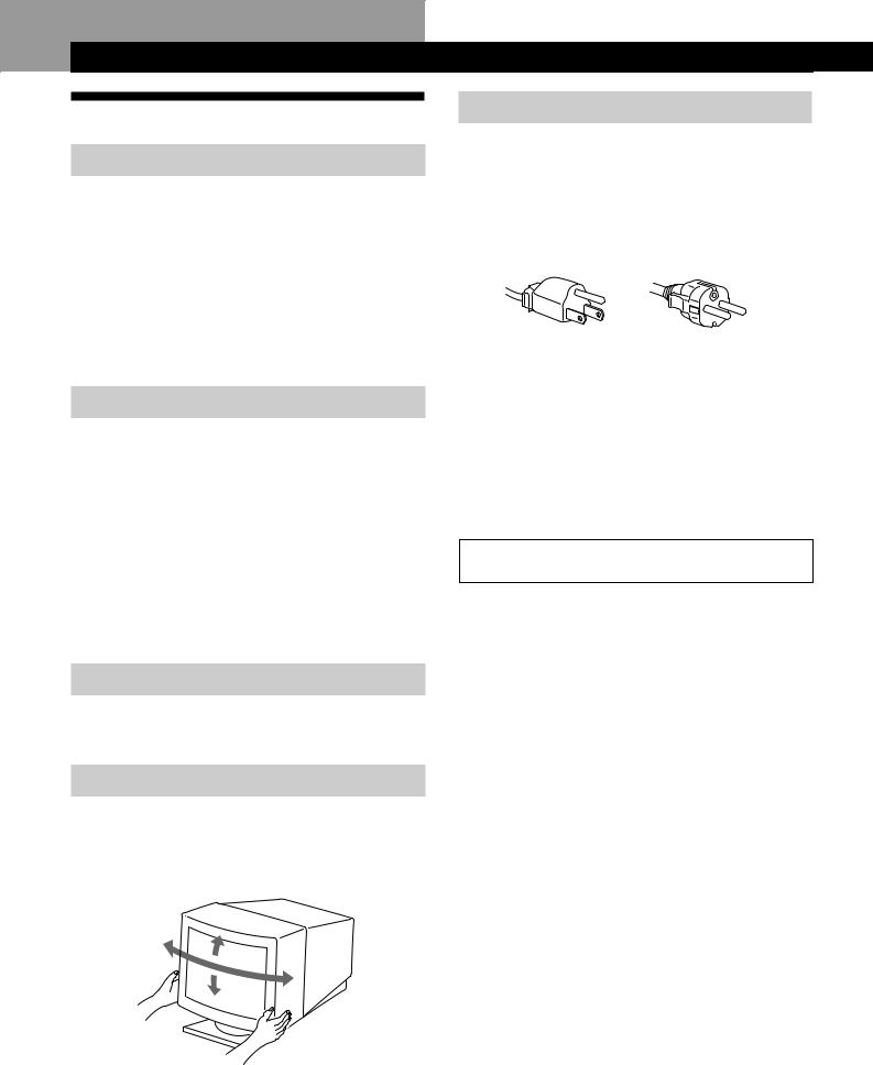
Use of the Tilt-Swivel
With the tilt-swivel, this monitor can be adjusted to the desired angle within 180° horizontally and 20° vertically. To turn the monitor vertically and horizontally, hold it at the bottom with both hands as illustrated below.
15°
90°
90°
5°
Warning on power connection
•Use an appropriate power cord for your local power supply.
For the customers in the U.S.A.
If you do not use the appropriate cord, this monitor will not conform to mandatory FCC standards.
Examples of plug types
for 100 to 120 V AC |
for 200 to 240 V AC |
•Before disconnecting the power cord, wait at least 30 seconds after turning off the power to allow the static electricity on the CRT display surface to discharge.
•After the power has been turned on, the CRT is demagnetized (degaussed) for about 3 seconds. This generates a strong magnetic field around the metal frame, which may affect the data stored on magnetic tapes and disks near the bezel. Place magnetic recording equipment, tapes and disks away from this monitor.
The outlet should be installed near the equipment and be easily accessible.
4
Getting Started
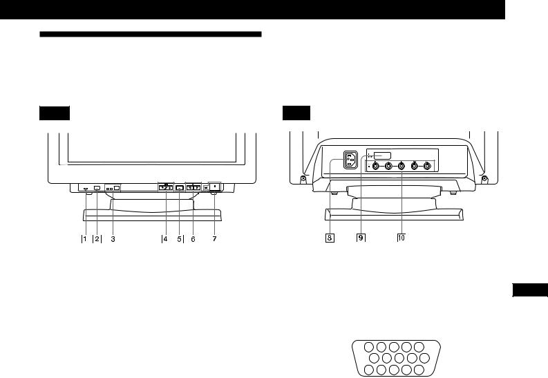
Identifying Parts and Controls
See the pages in parentheses for further details. GDM-500PS is used for illustration purposes throughout this manual.
Front |
Rear |


RESET |
HD15 BNC INPUT |
MENU |
ASC |
1RESET (reset) button (page 17)
Resets the adjustments to the factory settings.
2ASC (auto sizing and centering) button (page 7)
Automatically adjusts the size and centering of the images.
3INPUT (input) button and HD15/BNC indicators (page 8)
Selects the HD15 or 5BNC video input signal. Each time you press this button, the input signal and corresponding indicator alternate.
4¬ (brightness) (.>/ ) buttons (pages 8 –
17)
Adjust the picture brightness.
Function as the (./>) buttons when adjusting other items.
5MENU (menu) button (pages 8 -17)
Displays the MENU OSD.
6> (contrast) (?//) buttons (pages 8 – 17,
22)
Adjust the contrast.
Function as the (?//) buttons when adjusting other items.
7u (power) switch and indicator (pages 19,
22)
Turns the monitor on or off.
The indicator lights up in green when the monitor is turned on, and either flashes in green and orange or lights up in orange when the monitor is in power saving mode.
8AC IN connector
Provides AC power to the monitor.
9Video input 1 connector (HD15)
Inputs RGB video signals (0.700 Vp-p, positive) and SYNC signals.
|
5 |
4 |
|
3 |
2 |
1 |
|
|
|
10 |
9 |
8 |
7 |
6 |
|
||
|
15 |
14 |
13 12 |
11 |
|
|||
|
|
|
|
|
|
|
||
Pin No. |
Signal |
|
|
|
Pin No. |
Signal |
||
1 |
Red |
|
|
|
8 |
|
|
Blue Ground |
|
|
|
|
|
|
|
|
|
2 |
Green |
|
|
|
9 |
|
|
DDC + 5V* |
|
(Composite |
|
|
|
10 |
|
Ground |
|
|
Sync on Green) |
|
|
|
||||
|
|
|
11 |
|
ID (Ground) |
|||
|
|
|
|
|
|
|||
3 |
Blue |
|
|
|
||||
|
|
|
|
|
|
|
||
|
|
|
12 |
|
Bi-Directional |
|||
4 |
ID (Ground) |
|
|
|
|
|||
|
|
|
|
|
|
Data (SDA)* |
||
5 |
DDC Ground* |
|
|
13 |
|
H. Sync |
||
6 |
Red Ground |
|
|
|
14 |
|
V. Sync |
|
7 |
Green Ground |
|
|
15 |
|
Data Clock(SCL)* |
||
*Display Data Channel (DDC) Standard of VESA
!¼ Video input 2 connector (5 BNC)
Inputs RGB video signals (0.700 Vp-p, positive) and SYNC signals.
EN
F
ES
C
5
Getting Started
Setup
Before using this monitor, check that the following items are included in your carton:
•Monitor (1)
•Power cord (1)
•HD15 video signal cable (1)
•Macintosh adapter (1)
•Windows Monitor Information Disk (1)
•TCO’95 Eco-document (1) (GDM-500PS only)
•Warranty card (1)
•These operating instructions (1)
This monitor works with any IBM or compatible system equipped with VGA or greater graphics capability. Although this monitor works with other platforms running at horizontal frequencies between 30 and 94 kHz (GDM400PS), 30 and 107 kHz (GDM-500PS), including Macintosh and Power Macintosh systems, a cable adapter is required. Please consult your dealer for advice on which adapter is suitable for your needs.
Step 1: Connect the monitor to the
computer
With the computer switched off, connect the video signal cable to the monitor using the supplied HD15 video signal cable.
•If you are using an IBM PC/AT or compatible computer, refer to the section below.
•If you are using a Macintosh or compatible computer, refer to the following section, “Connecting to a Macintosh or compatible computer.”
•If you want to use the 5 BNC connectors, refer to the section, “Connecting to the 5 BNC connectors.”
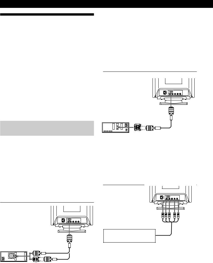
Connecting to an IBM PC/AT or compatible computer

to HD15
IBM PC/AT or |
|
compatible |
|
computer |
to video output |
HD15 video signal cable (supplied)
HD15 - HD15 adapter (not supplied)
*The HD15 - HD15 adapter may be needed for some models.
6
If your PC system is not compatible with DDC2AB and DDC2B+
This monitor uses the No. 9 pin in the video signal connector for DDC2AB and DDC2B+ compatibility.
Some PC systems which are not compatible with either DDC2AB or DDC2B+ may not accept the No. 9 pin. If you are not sure whether your PC system accepts the No. 9 pin or not, use the HD15 (Female) - HD15 (Male without the No. 9 pin) adapter (not supplied). Make sure the male side (without the No. 9 pin) is connected to the computer.
Connecting to a Macintosh or compatible computer

|
|
to HD15 |
Macintosh or |
|
|
compatible |
|
|
computer |
to video output |
HD15 video |
|
|
|
|
|
signal cable |
|
|
(supplied) |
|
Macintosh adapter |
|
|
(supplied) |
|
About the supplied Macintosh adapter
The supplied Macintosh adapter is compatible with Macintosh LC, Performa, Quadra, Power Macintosh and Power Macintosh G3 series computers.
Macintosh II series and some older versions of Power Book models may need an adapter with micro switches (not supplied).
Connecting to the 5 BNC connectors


to VIDEO IN R/G/B to SYNC IN HD/VD
Connect to the computer in the same way as for the HD15 connector.
To connect the 5 BNC connectors, use the SMF-400 video signal cable (sold separately). Connect the cables from left to right in the following order: Red–Green–Blue–HD–VD.
Notes
•Do not short the pins of the video signal cable.
•The DDC standard does not apply to the 5 BNC connectors. If you use the DDC standard, connect the HD15 connector to the computer with the supplied video signal cable.
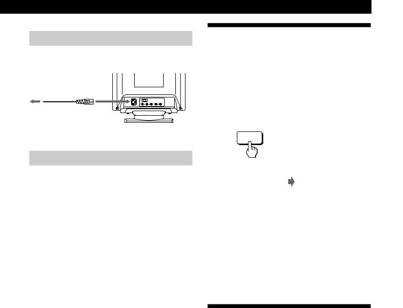
Step 2: Connect the power cord
With the monitor switched off, connect one end of the power cord to the monitor and the other end to a power outlet. 
to a power outlet to AC IN

Power cord (supplied)
Step 3: Turn on the monitor and computer
The installation of your monitor is complete.
Note
If “OUT OF SCAN RANGE” or “NO INPUT SIGNAL” appears on the screen, see “Warning Messages” on page 20.
For customers using Windows 95/98
To maximize the potential of your monitor, install the new model information file from the supplied Windows Monitor Information Disk onto your PC.
This monitor complies with the “VESA DDC” Plug & Play standard. If your PC/graphics board complies with DDC, select “Plug & Play Monitor (VESA DDC)” or this monitor’s model name as the monitor type in the “Control Panel” of Windows 95/98.
If your PC/graphics board has difficulty communicating with this monitor, load the Windows Monitor Information Disk and select this monitor’s model name as the monitor type.
For customers using Windows NT4.0
Monitor setup in Windows NT4.0 is different from Windows 95/98 and does not involve the selection of monitor type. Refer to the Windows NT4.0 instruction manual for further details on adjusting the resolution, refresh rate, and number of colors.
Getting Started
Automatically Adjusting the Size
and Centering of the Picture
By pressing the auto sizing and centering (ASC) button, the size and centering of the picture are automatically adjusted to fit the screen.
1Turn on the monitor and computer.
2Press the ASC button.
The picture is adjusted to fit the center of the screen.
ASC
|
|
|
|
|
|
|
|
|
|
|
|
|
|
|
|
|
|
Notes |
|
|
|
|
|
|
||
|
EN |
|||||||
• This function is intended for use with a computer running |
|
|||||||
|
|
|||||||
Windows or similar graphic user interface software that |
|
|||||||
provides a full-screen picture. It may not work properly if the |
F |
|||||||
background color is dark or if the input picture does not fill the |
|
|||||||
screen to the edges (such as an MS-DOS prompt). |
|
|||||||
ES |
||||||||
• The screen may go blank for a few seconds while performing the |
|
|||||||
auto-sizing function. This is not a malfunction. |
|
|||||||
C |
||||||||
• Although the signals for picture aspect ratio 5:4 (resolution: 1280 |
||||||||
|
||||||||
× 1024) do not fill the screen to the edges, the picture is |
|
|||||||
accurately displayed. |
|
|||||||
Selecting the On-screen Display
Language
If you need to change the OSD language, see “Using the LANG (Language) On-screen Display” on page 17.
The default setting is English.
7
Getting Started
Selecting the Input Signal
This monitor has two signal input connectors (HD15 and 5BNC) and can be connected to two computers. When the power of both computers is on, select the input signal you want to view as follows.
1Turn on the monitor and both computers.
2Press the INPUT button to select the HD15 or 5BNC input signal.
Each time you press the INPUT button, the input signal and corresponding indicator alternate.
HD15 BNC INPUT
Selecting the INPUT signal mode
This monitor has two modes of input signal selection, “AUTO” and “MANUAL.”
When “AUTO” is selected
If no signal is input from the selected connector, the monitor automatically selects the other connector’s signal. When you restart the computer you want to view, or that computer is in power saving mode, the monitor may automatically select the other connector’s signal. This is because the monitor switches from the interrupted signal to the constant signal. If this happens, manually select the desired signal using the INPUT button.
When “MANUAL” is selected
Even if no signal is input from the selected connector, the monitor does not select the other connector’s signal.
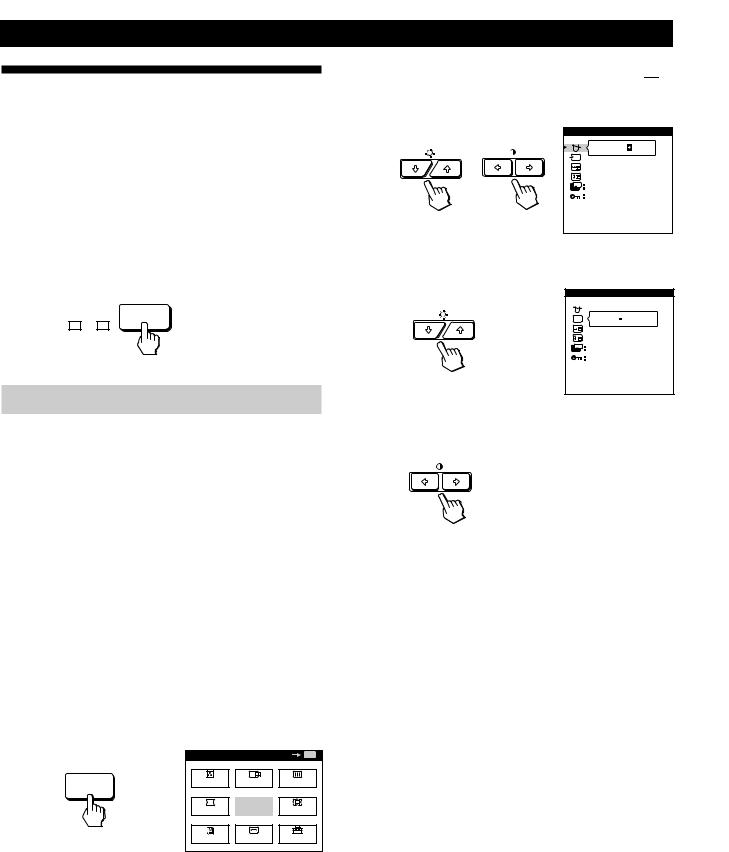
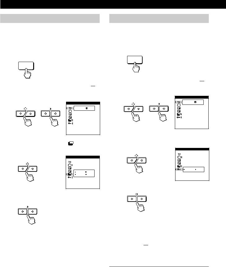
1Press the MENU button.
The MENU OSD appears.
MENU
MENU |
|
OK |
MENU |
COLOR |
CENTER SCREEN |
||
GEOM |
EXIT |
ZOOM |
|
LANG |
SIZE |
OPTION |
|
2Press the ¬./>and >?//buttons to select “ 


OPTION,” and press the MENU button again.
The OPTION OSD appears.
OPTION |
|
|
ON |
ZZ... |
1 MIN |
|
|
|
UNLOCK |
MANUAL DEGAUSS |
|
3 Press the ¬./>buttons to select “  (INPUT).”
OPTION


 AUTO MANUAL
ZZ... |
1 MIN |
|
|
|
UNLOCK |
|
INPUT |
4Press the >?//buttons to select “AUTO” or
“MANUAL.”
The OPTION OSD automatically disappears after about 30 seconds.
To close the OSD, press the MENU button again.
For more information on using the OSD, see “Introducing the On-screen Display System” on page 9.
8
Customizing Your Monitor
Before adjusting
•Connect the monitor and the computer, and turn them on.
•Select “ 
 LANG” in the MENU OSD, then select “ENGLISH” (see page 17).
Customizing Your Monitor
Introducing the On-screen
Display System
Most adjustments are made using the MENU OSD.
Adjusting the Picture Brightness
and Contrast
Once the setting is adjusted, it will be stored in memory for all input signals received.
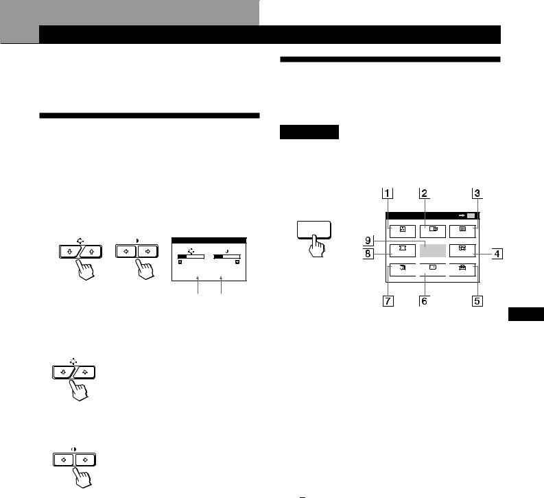
1Press the ¬ (brightness) ./>or > (contrast) ?// buttons.
The BRIGHTNESS/CONTRAST OSD appears.
BRIGHTNESS/CONTRAST
26 
 26 80.0kHz/ 75Hz
MENU OSD
Press the MENU button to display the MENU OSD.
This MENU OSD contains links to the other OSDs described below.
MENU |
OK MENU |
MENU |
CENTER SCREEN |
COLOR |
GEOM |
EXIT |
ZOOM |
LANG 
 SIZE
SIZE 
 OPTION
Horizontal Vertical
Frequency* Frequency*
2For brightness adjustment
Press the ¬./>buttons.
>. . . for more brightness
.. . . for less brightness
For contrast adjustment
Press the >?//buttons.
/. . . for more contrast ?. . . for less contrast
The OSD automatically disappears after about 3 seconds.
To reset, press the RESET button while the OSD is on. The brightness and contrast are both reset to the factory settings.
*The horizontal and vertical frequencies for the received input signal appear in the BRIGHTNESS/CONTRAST OSD.
1 

 COLOR
COLOR
Displays the COLOR OSD for adjusting the color temperature.
2 
 CENTER
Displays the CENTER OSD for adjusting the centering of the picture.
3  SCREEN
Displays the SCREEN OSD for adjusting the vertical and horizontal convergence, etc.
4  ZOOM
ZOOM
Displays the ZOOM OSD for enlarging and reducing the picture.
5 


 OPTION
Displays the OPTION OSD for adjusting the OSD position and degaussing the screen, etc.
6  SIZE
SIZE
Displays the SIZE OSD for adjusting the picture size.
7 
 LANG
LANG
Displays the LANGUAGE OSD for selecting the language.
8  GEOM
GEOM
EN
F
ES
C
Displays the GEOMETRY OSD for adjusting the picture rotation and pincushion, etc.
9EXIT
Closes the MENU OSD.
9

Customizing Your Monitor
Using the CENTER On-screen
Display
The CENTER settings allow you to adjust the centering of the picture.
Once the setting is adjusted, it will be stored in memory for the current input signal.
1Press the MENU button.
The MENU OSD appears.
MENU
2Press the ¬./>and >?//buttons to select “ 

CENTER,” and press the MENU button again.
The CENTER OSD appears.
CENTER
73
26
3For horizontal adjustment
Press the >?//buttons.
/. . . to move the picture right ?. . . to move the picture left
For vertical adjustment
Press the ¬./>buttons.
>. . . to move the picture up
.. . . to move the picture down
The OSD automatically disappears after about 30 seconds. To close the OSD, press the MENU button again.
To reset, press the RESET button while the OSD is on. The horizontal and vertical centerings are both reset to the factory settings.
Using the SIZE On-screen Display
The SIZE settings allow you to adjust the size of the picture. Once the setting is adjusted, it will be stored in memory for the current input signal.
1Press the MENU button.
The MENU OSD appears.
MENU
2Press the ¬./>and >?//buttons to select “ 
SIZE,” and press the MENU button again.
The SIZE OSD appears.
SIZE
73
26
3For horizontal adjustment
Press the >?//buttons.
/. . . to increase picture size ?. . . to decrease picture size
For vertical adjustment
Press the ¬./>buttons.
>. . . to increase picture size
.. . . to decrease picture size
The OSD automatically disappears after about 30 seconds. To close the OSD, press the MENU button again.
To reset, press the RESET button while the OSD is on.
The horizontal and vertical sizes are both reset to the factory settings.
10
Using the GEOM (Geometry) Onscreen Display
The GEOM (geometry) settings allow you to adjust the shape and orientation of the picture.
Once the rotation is adjusted, it will be stored in memory for all input signals received. All other adjustments will be stored in memory for the current input signal.
1Press the MENU button.
The MENU OSD appears.
MENU
2Press the ¬./>and >?//buttons to select “ 
GEOM,” and press the MENU button again.
The GEOMETRY OSD appears.
GEOMETRY
26
ROTATION
3Press the ¬./>buttons to select the item you want to adjust.
Select |
To |
ROTATION |
adjust the picture rotation |
PINCUSHION |
adjust the picture sides |
PIN BALANCE |
adjust the picture side balance |
KEYSTONE |
adjust the picture width |
KEY BALANCE |
adjust the picture shape balance |
Customizing Your Monitor
4 Press the >?//buttons to adjust the settings.
For |
Press |
|
|
ROTATION /. . . to rotate the picture clockwise
?. . . to rotate the picture counterclockwise
PINCUSHION /. . . to expand the picture sides
?. . . to contract the picture sides
PIN BALANCE |
/. . . to move the picture sides to the right |
|
|
|
|
EN |
|||
|
|
|
|
|
|
|
|
|
|
|
?. . . to move the picture sides to the left |
F |
||
|
|
|
|
|
|
|
|
|
ES |
KEYSTONE |
/. . . to increase the picture width at the |
|
||
|
top |
C |
||
|
?. . . to decrease the picture width at the |
|
||
|
top |
|
||
|
|
|
|
|
KEY BALANCE |
/. . . to move the top of the picture to |
|
||
|
the right |
|
||
?. . . to move the top of the picture to the left
The OSD automatically disappears after about 30 seconds. To close the OSD, press the MENU button again.
To reset, press the RESET button while the OSD is on.
The selected item is reset to the factory setting.
11

Customizing Your Monitor
Using the ZOOM On-screen
Display
The ZOOM settings allow you to enlarge or reduce the picture.
Once the setting is adjusted, it will be stored in memory for the current input signal.
1Press the MENU button.
The MENU OSD appears.
MENU
2Press the ¬./>and >?//buttons to select “ 
ZOOM,” and press the MENU button again.
The ZOOM OSD appears.
ZOOM
H |
|
|
|
|
|
|
|
|
26 |
|
|
|
|
|
|
|
|
||
V |
|
|
|
|
|
|
|
73 |
|
Using the COLOR On-screen Display
You can change the monitor’s color temperature. For example, you can adjust or change the colors of a picture on the screen to match the actual colors of the printed picture. Once the setting is adjusted, it will be stored in memory for all input signals received.
1Press the MENU button.
The MENU OSD appears.
MENU
2Press the ¬./>and >?//buttons to select “ 


COLOR,” and press the MENU button again.
The COLOR OSD appears.
COLOR
5000K 6500K 9300K
R BIAS 

 50
50
G BIAS 

 50
50
B BIAS 

 50
50
R GAIN 

 50
50
G GAIN 

 50
50
B GAIN 

 50
50
3 Press the >?//buttons to adjust the picture zoom.
3 Press the >?//buttons to select the color temperature.
/. . . to enlarge the picture ?. . . to reduce the picture
The OSD automatically disappears after about 30 seconds. To close the OSD, press the MENU button again.
To reset, press the RESET button while the OSD is on.
There are three color temperature modes in the OSD. The preset adjustments are:
5000K, 6500K, 9300K
Note
The picture zoom adjustment will stop as soon as either the horizontal or vertical size reaches its maximum or minimum value.
12

4Fine tuning the color temperature
Press the ¬./>buttons to select an item and adjust by pressing the >?//buttons.
COLOR
1 6500K 9300K
R BIAS 

 76
76
G BIAS 

 50
50
B BIAS 

 50
50
R GAIN 

 50
50
G GAIN 

 50
50
B GAIN 

 50
50
Select R (red), G (green), or B (blue) BIAS to adjust the black level of each color’s signal.
Select R (red), G (green), or B (blue) GAIN to adjust the white level of each color’s signal.
The “5000K,” “6500K” or “9300K” disappears and the new color settings are memorized for each of the three color modes.
The color temperature modes change as follows: 5000Kn1, 6500Kn2, 9300Kn3
The OSD automatically disappears after about 30 seconds. To close the OSD, press the MENU button again.
To reset, press the RESET button while the OSD is on. The selected item is reset to the factory settings.
Customizing Your Monitor
Using the SCREEN On-screen
Display
You can adjust convergence settings to eliminate red or blue shadows that may appear around objects on the screen. Adjust the CANCEL MOIRE function to eliminate wavy or elliptical patterns that may appear on the screen.
Adjust the LANDING function to correct color imbalances at the four corners of the screen due to influence from the earth’s magnetism.
Once CANCEL MOIRE is adjusted, it will be stored in memory for the current input signal. All other adjustments will be stored in memory for all input signals received.
1Press the MENU button.
The MENU OSD appears.
MENU
2 Press the ¬./>and >?//buttons to select “ 
SCREEN,” and press the MENU button again. |
EN |
|
The SCREEN OSD appears. |
|
|
SCREEN |
F |
|
|
||
TOP |
ES |
|
|
||
BOT |
|
|
26 |
C |
|
ADJ |
||
|
||
H CONVERGENCE |
|
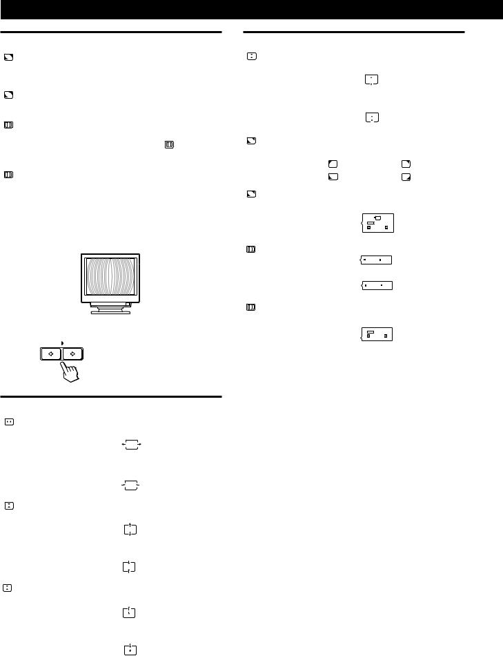
3Press the ¬./>buttons to select the item you want to adjust.
Select |
To |
|||||
|
|
|
|
|
|
|
|
|
|
|
|
adjust the horizontal convergence |
|
|
|
|
|
|
||
H CONVERGENCE |
|
|||||
|
|
|
|
|
|
|
|
|
|
|
|
adjust the vertical convergence |
|
V CONVERGENCE |
||||||
|
||||||
|
|
|
|
|
|
|
|
|
|
|
TOP |
adjust the screen’s upper vertical |
|
|
|
|
||||
V CONVER TOP |
convergence |
|||||
|
|
|
|
|
|
|
|
|
|
|
BOT |
adjust the screen’s lower vertical |
|
|
|
|
|
|||
V CONVER BOTTOM |
convergence |
|||||
|
|
|
|
|
|
|
|
|
|
|
|
(continued) |
|
13
Customizing Your Monitor
Select |
To |
|
|
|
|
|
select one of the four corners that |
|
LANDING |
needs color correction due to |
|
|
influence from the earth’s magnetism |
|
|
|
|
ADJ |
correct the color at one of the four |
|
LANDING ADJUST |
corners of the screen |
|
|
|
|
|
turn the moire cancellation function |
|
CANCEL MOIRE * |
“ON” or “OFF.” CANCEL MOIRE |
|
must be “ON” for “ ADJ (MOIRE |
||
|
||
|
ADJUST)” to appear on the screen. |
|
|
|
|
ADJ |
adjust the degree of moire |
|
MOIRE ADJUST |
cancellation |
|
|
|
*Moire is a type of natural interference which produces soft or wavy lines on your screen. It may appear due to interference between the regulated pattern of the picture from the input signal and the phosphor pitch pattern of the CRT.
Example of moire:
4 Press the >?//buttons to adjust the settings.
For |
Press |
||||||||||
|
|
|
|
|
|
|
|
|
|
|
|
|
|
|
|
|
/. . . to shift red shadows to the right |
||||||
|
|
|
|
|
|||||||
|
H CONVERGENCE |
and blue shadows to the left |
|||||||||
|
|
|
|
|
|
|
|
||||
|
|
|
|
|
|
|
|
|
|
|
|
|
|
|
|
|
|
|
|
|
|
|
|
|
|
|
|
|
?. . . to shift red shadows to the left |
||||||
|
|
|
|
|
and blue shadows to the right |
||||||
|
|
|
|
|
|
|
|
|
|
|
|
|
|
|
|
|
|
|
|
|
|
|
|
|
|
|
|
|
|
|
|
|
|
|
|
|
|
|
|
|
/. . . to shift red shadows up and blue |
||||||
|
|
|
|
|
|||||||
|
V CONVERGENCE |
shadows down |
|||||||||
|
|
|
|
|
|
|
|
||||
|
|
|
|
|
|
|
|
|
|
||
|
|
|
|
|
|
|
|
|
|
||
|
|
|
|
|
|
|
|
|
|
|
|
|
|
|
|
|
|
|
|
|
|
|
|
|
|
|
|
|
?. . . to shift red shadows down and |
||||||
|
|
|
|
|
blue shadows up |
||||||
|
|
|
|
|
|
|
|
|
|
|
|
|
|
|
|
|
|
|
|
|
|
|
|
|
|
|
|
|
|
|
|
|
|
|
|
|
|
|
|
|
|
|
|
|
|
|
|
|
|
|
|
|
|
|
|
|
|
|
|
|
|
|
|
TOP |
/. . . to shift red shadows up and blue |
||||||
|
|
|
|
||||||||
|
V CONVER TOP |
shadows down |
|||||||||
|
|
|
|
|
|
|
|
||||
|
|
|
|
|
|
|
|
||||
|
|
|
|
|
?. . . to shift red shadows down and |
||||||
|
|
|
|
|
blue shadows up |
||||||
|
|
|
|
|
|
|
|
|
|
|
|
|
|
|
|
|
|
|
|
|
|
|
|
For |
Press |
|
|
|
|
||||||
|
|
|
|
|
|
|
|
||||
|
|
BOT |
/. . . to shift red shadows up and blue |
||||||||
|
|
||||||||||
|
|
||||||||||
V CONVER BOTTOM |
shadows down |
||||||||||
|
|
|
|
|
|
|
|
|
|||
|
|
|
|
|
|
|
|
|
|
|
|
|
|
|
?. . . to shift red shadows down and |
||||||||
|
|
|
blue shadows up |
||||||||
|
|
|
|
|
|
|
|
|
|
|
|
|
|
|
|
|
|
|
|
||||
|
|
|
/or ?. . . to select the corner of the |
||||||||
LANDING |
screen you want to adjust |
||||||||||
|
|
|
: top left |
|
|
|
: top right |
||||
|
|
|
: bottom left |
|
|
|
: bottom right |
||||
|
|
|
|
|
|
|
|
||||
|
|
ADJ |
/or ?. . . to reduce any irregularities in |
||||||||
LANDING ADJUST |
the color to a minimum |
||||||||||
|
|
|
|
|
|
|
|
|
|
||
|
|
|
50 |
|
|
|
|
||||
|
|
|
|
|
|
|
|
||||
|
|
|
/. . . to turn CANCEL MOIRE “ON” |
||||||||
CANCEL MOIRE |
OFF |
ON |
|||||||||
|
|
|
|
|
|
|
|
|
|||
|
|
|
?. . . to turn CANCEL MOIRE “OFF” |
||||||||
|
|
|
|
OFF |
ON |
||||||
|
|
|
|
|
|
|
|
||||
|
|
ADJ |
/or ?. . . to adjust the screen until the |
||||||||
MOIRE ADJUST |
moire is at a minimum |
||||||||||
|
|
|
|
|
|
|
|
|
|
||
|
|
|
50 |
|
|
|
|
||||
|
|
|
|
|
|
|
|
|
|
|
|
Note
The picture may become fuzzy when CANCEL MOIRE is set to “ON.”
The OSD automatically disappears after about 30 seconds. To close the OSD, press the MENU button again.
To reset, press the RESET button while the OSD is on. The selected item is reset to the factory setting.
14

Using the OPTION On-screen
Display
The OPTION OSD allows you to manually degauss the screen and adjust settings such as the OSD position and power saving delay time. It also allows you to lock the controls.
Degaussing the screen
The monitor screen is automatically degaussed (demagnetized) when the power is turned on. You can also manually degauss the monitor.
1Press the MENU button.
The MENU OSD appears.
MENU
2Press the ¬./>and >?//buttons to select “ 
OPTION,” and press the MENU button again.
The OPTION OSD appears.
OPTION |
|
|
ON |
ZZ... |
1 MIN |
|
|
|
UNLOCK |
MANUAL DEGAUSS |
|
3Press the ¬./>buttons to select “  (MANUAL
DEGAUSS).”
4Press the > /button.
The screen is degaussed for about 3 seconds.
If you need to degauss the screen a second time, wait for at least 20 minutes before repeating the steps above.
The OPTION OSD automatically disappears after about 30 seconds.
To close the OSD, press the MENU button again.
Customizing Your Monitor
Changing the on-screen display position
You can change the OSD position (for example, when you want to adjust the picture behind the OSD).
1Press the MENU button.
The MENU OSD appears.
MENU
2Press the ¬./>and >?//buttons to select “ 


OPTION,” and press the MENU button again.
The OPTION OSD appears.
OPTION |
|
|
ON |
ZZ... |
1 MIN |
|
|
|
UNLOCK |
MANUAL DEGAUSS |
|
|
EN |
3 Press the ¬./>buttons to select “ |
|
(OSD H |
|
|||||
F |
||||||||
|
||||||||
POSITION)” or “ |
|
(OSD V POSITION).” |
||||||
|
|
|||||||
Select “ |
|
|
|
|
|
|||
|
(OSD H POSITION)” to adjust the horizontal |
|
||||||
ES |
||||||||
|
||||||||
position. |
|
|
|
|
|
|
||
|
|
|
|
|
|
|
||
OPTION |
C |
|
|
|
|
ZZ... |
1 MIN |
|
|
|
|
|
UNLOCK |
|
|
OSD H POSITION |
|
Select “  (OSD V POSITION)” to adjust the vertical position.
OPTION |
AUTO |
ZZ... |
UNLOCK |
OSD V POSITION |
4Press the >?//buttons to move the OSD to the desired position.
The OPTION OSD automatically disappears after about 30 seconds.
To close the OSD, press the MENU button again.
To reset, press the RESET button while the OSD is on. 15
Customizing Your Monitor
Setting the power saving delay time
You can set the delay time before the monitor enters the power saving mode. See page 19 for more information on this monitor’s power saving capabilities.
1Press the MENU button.
The MENU OSD appears.
MENU
2Press the ¬./>and >?//buttons to select “ 


OPTION,” and press the MENU button again.
The OPTION OSD appears.
OPTION |
|
|
ON |
ZZ... |
1 MIN |
|
|
|
UNLOCK |
MANUAL DEGAUSS |
|
3Press the ¬./>buttons to select “  ZZ... (PWR SAVE
DELAY).”
OPTION |
|
|
|
AUTO |
|
|
5 SEC |
1 MIN |
ZZ... |
60 MIN |
OFF |
|
||
|
PWR SAVE DELAY |
|
4 Press the >?//buttons to select the desired time.
When PWR SAVE DELAY is set to “OFF,” the monitor does not go into power saving mode.
The OPTION OSD automatically disappears after about 30 seconds.
To close the OSD, press the MENU button again.
To reset, press the RESET button while the OSD is on.
Locking the controls
The control lock function disables all of the buttons on the front panel except the u(power) switch and MENU button.
1Press the MENU button.
The MENU OSD appears.
MENU
2Press the ¬./>and >?//buttons to select “ 


OPTION,” and press the MENU button again.
The OPTION OSD appears.
OPTION |
|
|
ON |
ZZ... |
1 MIN |
|
|
|
UNLOCK |
MANUAL DEGAUSS |
|
3Press the ¬./>buttons to select “ (CONTROL
LOCK).”
OPTION |
|
AUTO |
|
ZZ... |
|
UNLOCK |
LOCK |
CONTROL LOCK |
|
4 Press the >?//buttons to select “LOCK.”
The OPTION OSD automatically disappears after about 30 seconds.
To close the OSD, press the MENU button again.
Once you select “LOCK,” you cannot select any items except “EXIT” and “ 


 OPTION” in the MENU OSD.
If you press any button other than the u(power) switch and MENU button, the  mark appears on the screen.
To cancel the control lock
Repeat steps 1 through 3 above and press the >?// buttons to select “UNLOCK.”
16
Using the LANG (Language) Onscreen Display
English, French, German, Spanish, Italian and Japanese versions of the OSDs are available.
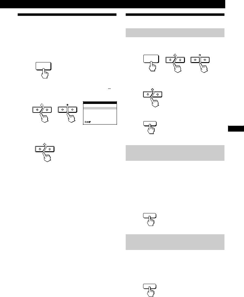
1Press the MENU button.
The MENU OSD appears.
MENU
2Press the ¬./>and >?//buttons to select “ 

LANG,” and press the MENU button again.
The LANGUAGE OSD appears.
LANGUAGE
 ENGLISH
FRANÇAIS
DEUTSCH
ESPAÑOL
I TALIANO
3Press the ¬./>buttons to select the desired language.
ENGLISH: English, FRANÇAIS: French,
DEUTSCH: German, ESPAÑOL: Spanish,
ITALIANO: Italian, or 
 : Japanese.
The OSD automatically disappears after about 30 seconds. To close the OSD, press the MENU button again.
To reset to English, press the RESET button while the OSD is on.
Customizing Your Monitor
Resetting the Adjustments
Resetting an adjustment item
1Press the MENU, ¬./>and >?//buttons to select the OSD containing the item you want to reset.
MENU
2Press the ¬./>buttons to select the item you want to reset.
3Press the RESET button.
RESET
|
EN |
|
F |
Resetting all of the adjustment data for |
ES |
the current input signal |
C |
|
When there is no OSD displayed, press the RESET button.
All of the adjustments data for the current input signal is reset to the factory settings.
Note that adjustment data not affected by changes in input signal (OSD language, OSD position, input signal selection, power saving delay time and the control lock function) is not reset to the factory settings.
RESET
Resetting all of the adjustment data for all
input signals
Press and hold the RESET button for more than two seconds.
All of the adjustment data, including the brightness and contrast, is reset to the factory settings.
RESET
17

Technical Features
Preset and User Modes
This monitor has factory preset modes for the most popular industry standards for true “plug and play” compatibility.
When a new input signal is entered, the monitor selects the appropriate factory preset mode and momentarily adjusts the phase calibration to provide a high quality picture to the center of the screen. The calibration is stored in memory and is immediately recalled whenever the same input signal is received.
Resolution Horizontal Vertical
No. |
(dots × lines) Frequency Frequency Graphics Mode |
||||
1 |
640 × 350 |
31.5 kHz |
70 Hz |
MCGA |
|
|
|
|
|
|
|
2 |
640 × 480 |
31.5 kHz |
60 Hz |
VGA-G |
|
|
|
|
|
|
|
3 |
640 × 480 |
37.5 kHz |
75 Hz |
EVGA |
|
|
|
|
|
|
|
4 |
640 × 480 |
43.3 kHz |
85 Hz |
VESA |
|
|
|
|
|
|
|
5 |
720 × 400 |
31.5 kHz |
70 Hz |
VGA-Text |
|
|
|
|
|
|
|
6 |
720 × 400 |
37.9 kHz |
85 Hz |
VESA |
|
|
|
|
|
|
|
7 |
800 × 600 |
37.9 kHz |
60 Hz |
SVGA |
|
|
|
|
|
|
|
8 |
800 × 600 |
46.9 kHz |
75 Hz |
ESVGA |
|
|
|
|
|
|
|
9 |
800 × 600 |
53.7 kHz |
85 Hz |
VESA |
|
|
|
|
|
|
|
10 |
832 × 624 |
49.7 kHz |
75 Hz |
Macintosh |
|
|
|
|
|
|
16” Color |
|
|
|
|
|
|
11 |
1024 |
× 768 |
48.4 kHz |
60 Hz |
VESA |
|
|
|
|
|
|
12 |
1024 |
× 768 |
56.5 kHz |
70 Hz |
VESA |
|
|
|
|
|
|
13 |
1024 |
× 768 |
60.0 kHz |
75 Hz |
EUVGA |
|
|
|
|
|
|
14 |
1024 |
× 768 |
60.2 kHz |
75 Hz |
Macintosh |
|
|
|
|
|
19” Color |
|
|
|
|
|
|
15 |
1024 |
× 768 |
68.7 kHz |
85 Hz |
VESA |
|
|
|
|
|
|
16 |
1152 |
× 864 |
67.5 kHz |
75 Hz |
VESA |
|
|
|
|
|
|
17 |
1152 |
× 870 |
68.7 kHz |
75 Hz |
Macintosh |
|
|
|
|
|
21” Color |
|
|
|
|
|
|
18 |
1280 |
× 960 |
60.0 kHz |
60 Hz |
VESA |
|
|
|
|
|
|
19 |
1280 |
× 960 |
85.9 kHz |
85 Hz |
VESA |
|
|
|
|
|
|
20 |
1280 |
× 1024 |
64.0 kHz |
60 Hz |
VESA |
|
|
|
|
|
|
21 |
1280 |
× 1024 |
80.0 kHz |
75 Hz |
VESA |
|
|
|
|
|
|
22 |
1280 |
× 1024 |
91.1 kHz |
85 Hz |
VESA |
|
|
|
|
|
|
23 |
1600 |
× 1200 |
75.0 kHz |
60 Hz |
VESA |
|
|
|
|
|
|
24 |
1600 |
× 1200 |
81.3 kHz |
65 Hz |
VESA |
|
|
|
|
|
|
25 |
1600 |
× 1200 |
87.5 kHz |
70 Hz |
VESA |
|
|
|
|
|
|
26 |
1600 |
× 1200 |
93.8 kHz |
75 Hz |
VESA |
|
|
|
|
|
|
27 * |
1600 |
× 1200 |
106.3 kHz |
85 Hz |
VESA |
|
|
|
|
|
|
* GDM-500PS only
For input signals that do not match one of the factory preset modes, the digital Multiscan technology of this monitor performs all of the adjustments necessary to ensure that a clear picture appears on the screen for any timing in the monitor’s frequency range. However, it may be necessary to fine tune the vertical/horizontal size and centering. Simply press the ASC button or adjust the monitor according to the adjustment instructions. The adjustments are stored automatically as a user mode and recalled whenever the corresponding input signal is received.
Recommended horizontal and vertical timing conditions
Horizontal sync width duty should be: >4.8% of total horizontal time.
Horizontal blanking width should be: >2.5 µsec. Vertical blanking width should be: > 450 µsec.
Note for Windows users
For Windows users, check your video board manual or the utility program which comes with your graphic board and select the highest available refresh rate to maximize monitor performance.
Adjusting the monitor’s resolution and color number
Adjust the monitor’s resolution and color number by referring to your computer’s instruction manual. The color number may vary according to your computer or video board. The color palette setting and the actual number of colors are as follows:
•High Color (16 bit) n65,536 colors
•True Color (24 bit) nabout 16.77 million colors In true color mode (24 bit), speed may be slower.
18
Power Saving Function
This monitor meets the power-saving guidelines set by VESA and Energy Star, as well as the more stringent NUTEK .
If the monitor is connected to a computer or video graphics board that is VESA DPMS (Display Power Management Signaling) compliant, the monitor will automatically reduce power consumption in three stages as shown below.
Technical Features
You can set the delay time before the monitor enters the power saving mode using the OSD. Set the time according to “Setting the power saving delay time” on page 16.
Note
If no video signal is input to the monitor, the “NO INPUT SIGNAL” message (page 20) appears. After the delay time has passed, the power saving function automatically puts the monitor into the active-off mode and the uindicator lights up orange. Once the horizontal and vertical sync signals are detected, the monitor automatically resumes its normal operation mode.
|
Power consumption |
Screen |
Horizontal |
Vertical |
Power consumption |
Recovery time |
u indicator |
|
mode |
|
sync signal |
sync signal |
|
|
|
1 |
Normal operation |
active |
present |
present |
≤ 145 W (GDM-500PS) |
— |
Green |
|
|
|
|
|
≤ 125 W (GDM-400PS) |
|
|
2 |
Standby (1st mode) |
blank |
absent |
present |
Approx. 72 W (GDM-500PS) |
Approx. 3 sec. |
Green and orange |
|
|
|
|
|
Approx. 65 W (GDM-400PS) |
|
alternate |
|
|
|
|
|
|
|
|
3 |
Suspend (2nd mode) |
blank |
present |
absent |
Approx. 8 W |
Approx. 3 sec. |
Green and orange |
|
|
|
|
|
|
|
alternate |
|
|
|
|
|
|
|
|
4 |
Active-off (3rd mode) |
blank |
absent |
absent |
Approx. 4 W |
Approx. 10 sec. |
Orange |
5 |
Power-off |
— |
— |
— |
0 W |
— |
Off |
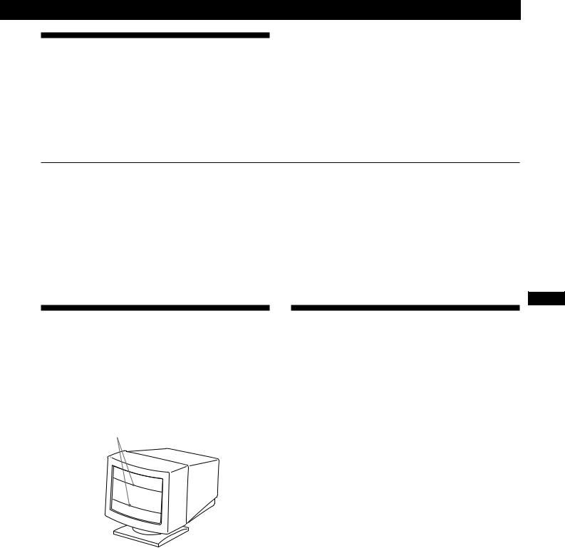
Damper Wires
When viewing a white background, very thin horizontal lines may be visible on the screen as shown below. These lines are the shadows of the damper wires and are characteristic of CRTs that use aperture grilles. The wires are attached to the aperture grille on the inside of the Trinitron tube and prevent the vibration of the aperture grille.
Damper wires
Plug & Play
This monitor complies with the DDC 1, DDC2B, DDC2AB and DDC2B+ Display Data Channel (DDC) standards of VESA.
When a DDC1 host system is connected, the monitor synchronizes with the V. CLK in accordance with the VESA standards and outputs the EDID (Extended Display Identification Data) to the data line.
When a DDC2B, DDC2AB or DDC2B+ host system is connected, the monitor automatically switches to the appropriate standard.
DDC is a trademark of the Video Electronics Standard Association.
Note
When using Windows 95/98, the DDC standard does not apply to the 5 BNC connectors. If you use the DDC standard, connect the HD15 connector to the computer with the supplied video signal cable.
EN
F
ES
C
19
 Loading...