


42PV1/42PV1P/42PV1A-FWD
2-581-145-01 (1)
Flat Panel Display
|
|
JP |
|||||
|
|
|
|
|
|
|
|
Operating Instructions |
|
|
GB |
||||
|
|
|
|
|
|
|
|
Mode d’emploi |
|
|
|
|
|
FR |
|
|
|
|
|
|
|||
Bedienungsanleitung |
|
|
|
DE |
|||
|
|
|
|
||||
Manual de instrucciones |
|
ES |
|||||
|
|
|
|
|
|||
Istruzioni per l’uso |
|
|
|
|
IT |
||
|
|
|
|||||
|
CS |
||||||
|
|
|
|
|
|
|
|
安全にお使いください。お読みになったあとは、いつでも見られるとこ ろに必ず保管してください。
FWD-42PV1/42PV1P/42PV1A
2005 Sony Corporation
WARNING
Owner’s Record
The model and serial numbers are located on the rear. Record the model and serial numbers in the spaces provided below. Refer to these numbers whenever you call upon your Sony dealer regarding this product.
Model No. |
|
Serial No. |
|
To prevent fire or shock hazard, do not expose the unit to rain or moisture.
To avoid electrical shock, do not open the cabinet. Refer servicing to qualified personnel only.
On transportation
When you carry the display unit, hold the unit itself, not the speakers. If you fail to do so, the speakers may come out of the unit and the unit may fall. This can cause injury.
For customers in the U.S.A.
If you have any questions about this product, you may
call; Sony Customer Information Services Center
1-800-222-7669 or http://www.sony.com/
Declaration of Conformity
Trade Name: |
SONY |
Model: |
FWD-42PV1/42PV1P/42PV1A |
Responsible Party: |
Sony Electronics Inc. |
Address: |
16450 W. Bernardo Dr, San Diego, |
|
CA 92127 U.S.A. |
Telephone Number: |
858-942-2230 |
This device complies with Part 15 of the FCC Rules. Operation is subject to the following two conditions: (1) This device may not cause harmful interference, and (2) this device must accept any interference received, including interference that may cause undesired operation.
This equipment has been tested and found to comply with the limits for a Class B digital device, pursuant to Part 15 of the FCC Rules. These limits are designed to provide reasonable protection against harmful interference in a residential installation. This equipment generates, uses, and can radiate radio frequency energy and, if not installed and used in accordance with the instructions, may cause harmful interference to radio communications. However, there is no guarantee that interference will not occur in a particular installation. If this equipment does cause harmful interference to radio or television reception, which can be determined by turning the equipment off and on, the user is encouraged to try to correct the interference by one or more of the following measures:
•Reorient or relocate the receiving antenna.
•Increase the separation between the equipment and receiver.
•Connect the equipment into an outlet on a circuit different from that to which the receiver is connected.
•Consult the dealer or an experienced radio/TV technician for help.
You are cautioned that any changes or modifications not expressly approved in this manual could void your authority to operate this equipment.
For customers in Canada
This class B digital apparatus complies with Canadian ICES-003.
Voor de klanten in Nederland
•Dit apparaat bevat een vast ingebouwde batterij die niet vervangen hoeft te worden tijdens de levensduur van het apparaat.
•Raadpleeg uw leverancier indien de batterij toch vervangen moet worden. De batterij mag alleen vervangen worden door vakbekwaam servicepersoneel.
•Gooi de batterij niet weg maar lever deze in als klein chemisch afval (KCA).
• Lever het apparaat aan het einde van de |
|
levensduur in voor recycling, de batterij zal |
|
dan op correcte wijze verwerkt worden. |
NL |
|
The socket-outlet should be installed near the equipment and be easily accessible.
CAUTION
RISK OF EXPLOSION IF BATTERY IS REPLACED BY AN INCORRECT TYPE. DISPOSE OF USED BATTERIES ACCORDING TO THE LOCAL RULES.
2 (GB)

Table of Contents
Precautions ............................................................... |
5 |
(GB) |
|
Location and Function of Parts and Controls ....... |
7 |
(GB) |
|
Front / Rear / Left side / Right side / Bottom .......... |
7 |
(GB) |
|
Indicator Section ...................................................... |
8 |
(GB) |
|
Control Button Section (Top) .................................. |
8 |
(GB) |
|
Connector Panel (Bottom) ....................................... |
9 |
(GB) |
|
Connector Panel (Left side) ................................... |
10 |
(GB) |
|
Remote Commander RM-980 ................................ |
12 |
(GB) |
|
Caution .................................................................... |
14 |
(GB) |
|
Connections ............................................................ |
15 |
(GB) |
|
Connecting the Speakers ........................................ |
15 |
(GB) |
|
Connecting the AC Power Cord ............................ |
15 |
(GB) |
|
Cable management ................................................. |
16 |
(GB) |
|
Using On-screen Menus ........................................ |
17 |
(GB) |
|
Operating Through Menus ..................................... |
17 |
(GB) |
|
Menu Guide ........................................................... |
17 |
(GB) |
|
Watching the Picture .............................................. |
23 |
(GB) |
|
Switching the Input Signal ..................................... |
23 |
(GB) |
|
Input Signal, Picture Mode and Display Status |
|
|
|
Information ....................................................... |
24 |
(GB) |
|
Selecting Image Quality ......................................... |
26 |
(GB) |
|
Adjusting the Picture ............................................. |
26 |
(GB) |
|
Adjusting the Contrast, Brightness, Chroma, and |
|
|
|
Phase, etc. ......................................................... |
26 |
(GB) |
|
Restoring the Adjust Picture Menu Items to Their |
|
|
|
Original Settings ............................................... |
28 |
(GB) |
|
Picture Enlargement ............................................... |
29 |
(GB) |
|
Setting Auto Wide ................................................. |
29 |
(GB) |
|
Setting the Aspect .................................................. |
30 |
(GB) |
|
Resizing and Positioning the Picture ................... |
31 |
(GB) |
|
Adjusting the Size, Position, or the Pixels of |
|
|
|
the Picture ......................................................... |
31 |
(GB) |
|
Restoring the adjusted Size or Position to Their |
|
|
|
Original Settings ............................................... |
32 |
(GB) |
|
Viewing two pictures at the same time ................. |
33 |
(GB) |
|
Activating a picture or swapping the positions of |
|
|
|
two pictures ....................................................... |
33 |
(GB) |
|
GB
English
3 (GB)
Zooming in on a picture ......................................... |
34 (GB) |
Adjusting the position of the inset picture |
|
(For PinP only) ................................................. |
34 (GB) |
Setting up the Multi Display .................................. |
35 (GB) |
Adjusting the Sound Quality ................................. |
36 (GB) |
Adjusting the Treble, Bass, and Balance, etc. ....... |
36 (GB) |
Restoring the Adjust Sound Menu Items to Their |
|
Original Settings ............................................... |
36 (GB) |
Selecting the On-screen Language ...................... |
37 (GB) |
Adjusting Color Matrix ........................................... |
37 (GB) |
Controlling Power On/Off Automatically (Timer |
|
Function)............................................................. |
38 (GB) |
Adjusting the time and the day .............................. |
38 (GB) |
Displaying the time ................................................ |
38 (GB) |
On/Off Timer Function .......................................... |
39 (GB) |
SCREEN SAVER Function ..................................... |
40 (GB) |
Reversing the Color Tones of the Image ............... |
40 (GB) |
Changing the Image Position Automatically ......... |
41 (GB) |
Turning the screen all white ................................... |
41 (GB) |
Adjusting the brightness of background of |
|
picture ............................................................... |
41 (GB) |
Lowers the brightness level gradually ................... |
42 (GB) |
Setting an IP address and communication |
|
speed................................................................... |
42 (GB) |
Obtaining an IP address automatically (DHCP) .... |
42 (GB) |
Setting an IP address manually (Manual) .............. |
42 (GB) |
Setting a communication speed ............................. |
43 (GB) |
Self-diagnosis Function ......................................... |
43 (GB) |
Operating a Specific Display With the Remote |
|
Commander ........................................................ |
44 (GB) |
Specifications ......................................................... |
45 (GB) |
4 (GB)

Precautions
On safety
•A nameplate indicating operating voltage, power consumption, etc. is located on the rear of the unit.
•Should any solid object or liquid fall into the cabinet, unplug the unit and have it checked by qualified personnel before operating it any further.
•Unplug the unit from the wall outlet if it is not to be used for several days or more.
•To disconnect the AC power cord, pull it out by grasping the plug. Never pull the cord itself.
•When you install the unit on the floor, be sure to use the optional stand.
On installation
•Allow adequate air circulation to prevent internal heat build-up. Do not place the unit on surfaces (rugs, blankets, etc.) or near materials (curtains, draperies) that may block the ventilation holes.
•Do not install the unit in a location near heat sources such as radiators or air ducts, or in a place subject to direct sunlight, excessive dust, mechanical vibration or shock.
•When you install multiple equipment with the unit, the following problems, such as malfunction of the Remote Commander, noisy picture, noisy sound, may occur depending on the position of the unit and other equipment.
On the PDP (Plasma Display Panel)
•You may see some bright spots of red, blue or green remain, or dark spots appear on the screen. These do not indicate malfunction. Although the plasma display panel is manufactured with extremely high precision technology, it can generate a few dark or bright pixels. Dark spots on the edge of the screen, or striped color and brightness irregularities do not indicate malfunction.
•Do not display the same still image on the screen for a long time. Otherwise, an afterimage or ghost may appear on a part of the panel. Use the screen saver function to equalize use of the screen display.
•Because of the way it is made, when this plasma display panel is used in places with low air pressure, such as at high altitudes, a buzzing or humming noise may emanate from the unit.
Precautions
•If you continue to display the same image on the screen for a long period of time, part of that image may burn into the screen and leave a ghosting image behind. To avoid this, please use the screen saver function provided to equalize use over the entire screen. If ghosting occurs, use the screen saver function, or use some kind of video or imaging software to provide constant movement on the screen. If light ghosting (image burn-in) occurs,it may become less conspicuous, but once burn-in occurs, it will never completely disappear.
•To protect the plasma display, this unit will not accept commands from the Remote Commander or from the function buttons on the unit for a certain period of time after the unit has been switched ON/ STANDBY. After one of these operations, wait about 5 seconds before entering a command.
On cleaning
•Be sure to unplug the power cord before cleaning the display.
•Gently wipe off stains using a dry, soft cloth. Wipe off grimy stains using a cloth slightly moistened with a mild detergent, then wipe the area again using a dry, soft cloth.
•Never use rubbing alcohol, benzine or thinner for cleaning. They may damage the finish of the cabinet or can remove the markings on it.
Notes on handling and cleaning the display panel
The display panel’s special surface finish should be treated with care when cleaning or handling the TV. When cleaning it, use a soft cleaning cloth to avoid touching the panel directly.
On repacking
Do not throw away the carton and packing materials. They make an ideal container in which to transport the unit. When shipping the unit, repack it as illustrated on the carton.
If you have any questions on this unit, contact your authorized Sony dealers.
5 (GB)

Precautions
Warning on power connection
Use the proper power cord for your local power supply.
|
United States, |
Continental |
United Kingdom, Ireland, |
Japan |
|
|
Canada |
Europe |
|
Australia, New Zealand |
|
Plug type |
VM0233 |
COX-07 |
636 |
—a) |
VM1296 |
Female end |
VM0089 |
COX-02 |
VM0310B |
VM0303B |
VM1313 |
|
|
|
|
|
|
Cord type |
SVT |
H05VV-F |
CEE (13) 53rd (O.C) |
HVCTF |
|
|
|
|
|
|
|
Minimum cord set rating |
10A/125V |
10A/250V |
10A/250V |
10A/125V |
|
|
|
|
|
|
|
Safety approval |
UL/CSA |
VDE |
|
VDE |
DENAN-HO |
|
|
|
|
|
|
a) Note: Use an appropriate rating plug which complies with local regulations.
6 (GB)

Location and Function
of Parts and Controls
Front / Rear / Left side / Right side / Bottom
Front |
|
|
|
|
|
|
|
|
|
|
1 |
Rear |
|
|
|
|
|
|
2 |
|
|
3 |
|
4 |
5 |
6 |
7 |
5 |
7 |
Left side |
|
|
|
|
|
|
|
7 |
|
|
|
|
|
5 |
|
|
|
Location and Function of Parts and Controls
Right side |
|
|
|
OUT AC |
4 |
|
|
|
|
R SPEAKER |
5 |
|
|
|
Bottom |
|
|
6 |
|
7 |
1Indicator section
For details on the Indicator section, see “Indicator Section” on page 8 (GB).
2Control button section
For details on the control button section, see “Control Button Section (Top)” on page 8 (GB).
3Stand installation hooks
Use these hooks to install the stand (not supplied).
4AC OUT socket (three brade type)
You can connect a device consuming small power to this socket and supply power when setting up an audio/visual system (the power rating: maximum 0.5 A). For more details, consult your Sony dealer.
Note
Be sure not to connect the device of which power consumption exceeds its rating.
5SPEAKER Socket
Connects the speakers (not supplied) to this socket to output the audio matching the signal displayed on the screen.
6- AC IN socket
Connect the supplied AC power cord to this socket and to a wall outlet. Once you connect the AC power cord, the POWER/STANDBY indicator lights up in red and the display goes into the standby mode.
For more details on the power cord, see “Connecting the AC Power Cord” on page 15 (GB).
7Connector panel
For details on the connector panel, see “Connector Panel (Bottom)” on page 9 (GB) and “Connector Panel (Left side)” on page 10 (GB).
7 (GB)
Location and Function of Parts and Controls
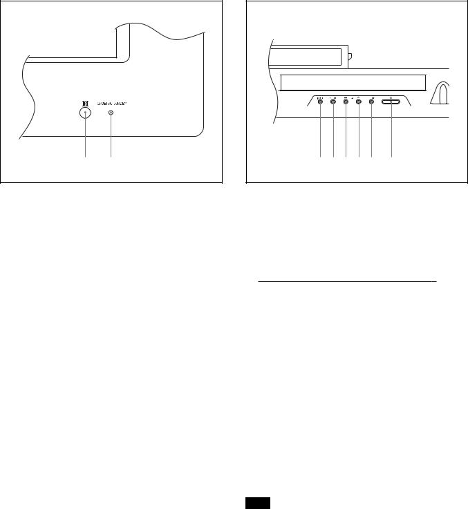
Indicator Section
1 |
2 |
1Remote control detector
Receives the signals from the Remote Commander.
2POWER/STANDBY indicator
Lights up in green when the display unit is powered on. Lights up in red in the standby mode. Lights up in orange when the display enters the power saving mode while a signal is input from a computer.
When the POWER/STANDBY indicator blinks, see “Selfdiagnosis Function” on page 43 (GB).
Control Button Section (Top)
1 2 3 4 5 |
6 |
1INPUT button
Press to select a signal to be input from the INPUT or OPTION1 connector.
The signal to be input switches as follows each time you press the INPUT1 button.

 INPUT1
  INPUT2
  OPTION1
When an option adaptor is not installed in the OPTION1 slot, OPTION1 will be skipped.
2MENU button
Press to show menus. Press again to hide them.
34m/M (cursor/volume) button
Press to move the cursor (yellow), set a value, or control speaker volume.
5ENTER button
Press to set your choice.
61POWER switch
Press to power on the display unit. Press again to return to the standby mode.
Note
To protect the panel, a certain amount of time is required to turn the unit ON/STANDBY. Wait about 5 seconds after one of these operations before executing the next operation.
8 (GB)

Location and Function of Parts and Controls
Connector Panel (Bottom)
1 |
2 |
3 |
4 |
5 |
|
|
IN OUT |
R |
L AUDIO |
DVI-HDCP |
AUDIO RGB/COMPONENT |
AC IN |
REMOTE |
CONTROL S |
AUDIO OUT |
INPUT 1 |
INPUT 2 |
|
1REMOTE (RS-232C) connector (D-sub 9-pin)
This connector allows remote control of the display using the RS-232C protocol. For details, contact your authorized Sony dealers.
2CONTROL S IN/OUT (Control S Signal Input/ Output) Connector (Minijack)
You can control multiple devices with a single remote commander when connected to the CONTROL S connector of a video device or other display. Connect the CONTROL S OUT connector on this display to the CONTROL S IN connector of the other device, and connect the CONTROL S IN connector on this display to the CONTROL S OUT connector of the other device.
3AUDIO OUT L/R (Pinjack)
Outputs an audio of the signal currently indicated on the screen.
Outputs an audio signal corresponding to the Active Picture while in the P&P or PinP mode.
4INPUT1 (DIGITAL RGB IN) connectors DVI : Connects to the digital RGB signal output of
video devices. Supports HDCP copy protection.
AUDIO (Stereo minijack) : Inputs an audio signal. Connects to the audio output of video devices.
5INPUT2 (ANALOG RGB/COMPONENT IN) connectors
RGB/COMPONENT (D-sub 15-pin) : Connects to the analog RGB signal or component (YUV) signal output of a piece of video equipment.
AUDIO (Stereo minijack) : Inputs an audio signal. Connects to the audio output of a piece of video equipment.
9 (GB)
Location and Function of Parts and Controls
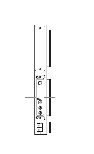
Connector Panel (Left side)
|
|
|
6 COMMUNICATION |
|
|
COMMUNICATION |
|
|
|
Slot |
|
|
|
|
|
|
|
|
|
7 (VIDEO/COM) 8 OPTION1
1 |
(VIDEO/COM) |
|
OPTION |
||
Slot |
||
|
||
SPEAKER L |
|
6COMMUNICATION slot
This slot supports commucation function.
A blank panel is attached to this slot for the factory setting.
When you install the optional adaptor BKM-FW32 (Network Management Adaptor) in this slot, you can control the display unit via the network.
7VIDEO connectors (A BKM-FW10 is preinstalled only in the FWD-42LX1/32LX1.)
S VIDEO IN (Mini DIN 4-pin) : Connects to the Y/ C signal output of a piece of video equipment.
S VIDEO OUT (Mini DIN 4-pin) : Connects to the Y/C signal input of a piece of video equipment.
VIDEO IN (BNC) : Connects to the video signal output of a piece of video equipment.
VIDEO OUT (BNC) : Connects to the video signal input of a piece of video equipment.
AUDIO IN L/R (Pinjack) : Inputs an audio signal. Connects to the audio output of a piece of video equipment.
8OPTION1 (VIDEO/COM) slot
This slot supports video signals and communication function.
10 (GB)
Optional adaptors (Not supplied)
The connectors marked with 7on the connector panel are slot-in types and can be fitted with any of the optional adaptors in the display; BKM-FW10, BKM-FW11 or BKM-FW12.
(A BKM-FW10 is the same as the connectors 7.)
For details on installation, consult your Sony dealers.
COMPONENT/RGB Input Adaptor BKM-FW11 (Not supplied)
|
Y/G |
ADAPTOR |
1 |
PB/CB/B |
|
2 |
VD HD PR/CR/R |
COMPONENT/RGBINPUT |
|
|
|
3 |
AUDIO |
|
1 Y/G PB/CB/B PR/CR/R IN (BNC) : Connects to the analog RGB signal or component (YUV) signal output of a piece of video equipment or a computer.
2 HD VD IN : Connects to the synchronization signal output of a computer.
3 AUDIO (Stereo minijack) : Inputs an audio signal. Connects to the audio output of a piece of video equipment or a computer.
Location and Function of Parts and Controls
RGB/COMPONENT ACTIVE THROUGH ADAPTOR BKM-FW12 (Not supplied)
1 |
IN |
THROUGH |
|
|
|
2 |
OUT |
RGB/COMPONENT |
|
|
|
3 |
AUDIO IN |
|
1RGB/COMPONENT IN (D-sub 15-pin) :
Connects to the component signal output or analog RGB signal output of a piece of video equipment or a computer.
For details on inputting a component signal to the connector, see “Pin assignment” on page 46 (GB).
2RGB/COMPONENT OUT (D-sub 15-pin) :
Connects to the component signal input or analog RGB signal input of a piece of video equipment or a computer.
3AUDIO IN (Stereo minijack) :
Inputs audio signal. Connects to the audio signal output of a piece of video equipment or a computer.
Note
When the unit is not connected to an AC power or is in the standby mode, no signal is output from the RGB/COMPONENT OUT.
For details on other optional adaptors (Not supplied), consult your Sony dealer.
11 (GB)
Location and Function of Parts and Controls
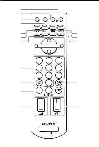
Remote Commander RM-980
1 |
|
|
|
|
|
|
|
|
||
2 |
MUTING DISPLAY STBY ON |
|||||||||
|
|
|||||||||
3 |
|
|
|
|
|
|
|
|
||
|
|
|
|
|
|
|
|
|||
4 |
|
|
|
|
|
|
|
|
||
5 |
|
|
|
|
|
|
|
qf |
||
6 |
|
|
|
|
|
|
|
qg |
||
|
|
|
|
|
|
|
||||
|
|
|
|
|
|
|
||||
7 |
|
|
|
|
|
|
|
qh |
||
8 |
|
|
|
|
|
|
|
qj |
||
9 |
|
|
|
|
|
|||||
ENTER |
||||||||||
|
|
|
|
|||||||
|
||||||||||
|
1 |
2 |
3 |
0 |
4 |
5 |
6 |
|
7 |
8 |
9 |
qa |
|
0 |
qk |
qs |
ON |
SET |
|
|
|
|
|
qd |
|
|
ql |
MONITOR
RM-980
1POWER ON switch
Press to power on the display.
2STANDBY button
Press to change the display to the standby mode.
3MUTING button
Press to mute the sound. Press again to restore sound.
4DISPLAY button
Press to display the input signal information and the picture mode on the screen. Press again to hide them. If this displayed information is left undisturbed for five minutes, it will disappear automatically.
5INPUT1 button
Press to select the signal input to the INPUT1 connectors.
6INPUT2 button
Press to select the signal input to the INPUT2 connectors. Each press toggles between RGB and COMPONENT.
7PICTURE button
Selects Picture mode. Each press toggles between Vivid, Standard, and User 1 to 3.
8ASPECT button
Press to change the aspect ratio (Wide Mode).
9M/m/</,/ENTER buttons
The M/m/</, buttons move the menu cursor (yellow) and set values, etc. Pressing the ENTER button sets the selected menu or setting items.
q;Number buttons
Press to enter index numbers.
qaBRIGHTNESS button
Adjusts the brightness when Picture Mode is set to any of “User1” to “User3.” Press this button, then adjust the brightness with M/m or </, buttons 9.
qsID MODE (ON/SET/OFF) buttons
Press ON to show an index number on the screen. Enter the index number of the display you want to operate with Number buttons 0, then press SET. Press OFF to return to the normal mode.
For details on the index numbers, see “Operating a Specific Display With the Remote Commander” on page 44 (GB).
qd VOLUME +/– button
Press to adjust the volume.
qfOPTION2 button
This button is invalid for this display unit.
qg OPTION1 button
When an option board is installed, selects a signal to be input from the device connected to the option board. Each time you press this button, the signal input to the OPTION1 switches.
qh MENU button
Press to show menus. Press again to hide them.
qj button
Selects the PICTURE AND PICTURE (PAP) mode. Each press toggles between PAP off, P&P, and PinP.
12 (GB)
Location and Function of Parts and Controls
qk CHROMA button
Adjusts the chroma when the picture mode is set to any of “User1” to “User3.” Press this button and adjust the chroma with the M/m or </, buttons 9.
qlCONTRAST +/– button
Adjusts the contrast when Picture Mode is set to any of “User1” to “User3.”
Installing batteries
Insert two size AAA (R03) batteries in correct polarity.
Be sure to |
install the |
negative <– |
end first. |
•In normal operation, batteries will last up to half a year. If the Remote Commander does not operate properly, the batteries might be exhausted sooner. Replace them with new ones.
•To avoid damage from possible battery leakage, remove the batteries if you do not plan to use the Remote Commander for a fairly long time.
When the Remote Commander does not work
Check that the POWER/STANDBY indicator lights up and the Control Mode in the Remote menu is not set to “Display Unit Only.” The Remote Commander operates the display only when both of the two conditions below are met.
•The display is turned on, or it is in the standby mode.
•The Control Mode in the Remote menu is set to
“Display + Remote” or “Remote Only.”
For details on the Control Mode, see “Control Mode” on page 20 (GB).
For Customers in Taiwan only
13 (GB)
Caution
Caution
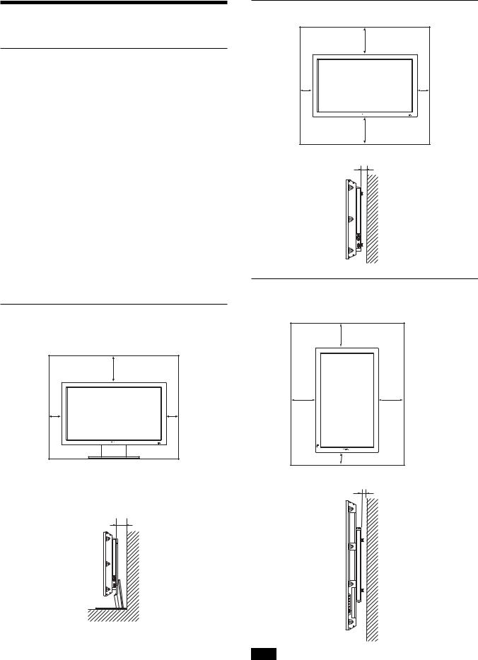
Provide an ample amount of space around the display
•When you use the display, make sure there is more space around the display than that shown in the figure below. This will allow for proper ventilation.
•The ambient temperature must be 0 °C to +35 °C (32 °F to 95 °F).
•When installing the display horizontally, use the display stand SU-42FW (not supplied) as a stand.
•Regarding the installation of hardware such as brackets, screws, or bolts, we cannot specify the products. Actual installation is up to the authorized local dealers. Consult with qualified Sony personnel for installation.
•While the unit is on, a certain amount of heat builds up inside. This can cause burns. Avoid touching the top or rear of the unit when it is powered on or just after it has entered standby mode.
When using the stand (not supplied)
Front
|
20 (7 7/8) |
10 |
10 |
(4) |
(4) |
Side
10 (4)
Units: cm (inches)
When mounting the display horizontally
Front |
|
|
25 (9 7/8) |
10 |
10 |
(4) |
(4) |
|
25 (9 7/8) |
Side |
5 (2) |
|
Units: cm (inches)
When mounting the display vertically (FWD-42PV1P)
Front |
|
20 (7 |
7/8) |
25 |
25 |
(9 7/8) |
(9 7/8) |
10 (4) |
|
Side |
5 (2) |
|
Units: cm (inches)
Note
You cannot attach the speakers (SS-SP42FW) to the FWD-42PV1P.
14 (GB)
Notes on Image Retention
If the 1– 5images (below) are displayed for an extended period of time, image retention (afterimage) in areas of the screen may result due to the characteristics of the Plasma Display Panel. It is
possible to reduce image retention by following steps
A– D.
Situations which can result in burn-in and picture retention
1Black bars at the top and bottom that appear
with wide video source (Letter box picture)
2Black bars to the left and right that appear with 4:3 video source (conventional TV broadcast)
3Video game sources
4DVD on-screen menu displays
5On-screen menus, channel numbers, etc., of connected equipment such as DSS, Cable box, video decks, etc.
Precautions to avoid/reduce burn-in and picture retention
AUse the SCREEN SAVER function.
BAvoid displaying channel numbers, on-screen menus etc., of connected equipment such as DSS, Cable box, video decks, etc. To erase channel numbers, on-screen menus, refer to the user manual of connected equipment.
CReduce brightness of the picture and/or display video source in Wide Zoom or Full Mode.
D“Pic. Inversion” and “All White” of “SCREEN SAVER” are effective in burn-in or after image reduction. However, the burn-in or after image cannot be completely removed once they occur.
Notes on “Pic. Inversion (Picture Inversion)” of “SCREEN SAVER”
If the displayed image appears as an image like a film negative, “Pic. Inversion (Picture Inversion)” of “SCREEN SAVER” may be set to “Auto” or “On.” To return to a normal image, select “Off” or reset the specified time in “Auto.”
Pic. Inversion (Picture Inversion) inverts the tint of the picture (Example: white to black, black to white) and corrects the image retention (afterimage) with displayed image on. The image looks like a film negative during picture inversion. This is not a malfunction.
Caution / Connections
Connections
Before you start
•First make sure that the power to each piece of equipment is turned off.
•Use connecting cables suitable for the equipment to be connected.
•The cable connectors should be fully inserted into the jacks. A loose connection may cause hum and other noise.
•To disconnect the cable, pull it out by grasping the plug. Never pull the cable itself.
•Refer to the instruction manual of the equipment to be connected.
•Insert the plug securely into the AC IN socket.
•Use one of the two AC plug holders (supplied) that will securely hold the AC plug.
Connecting the Speakers
You can enjoy viewing with a greater sense of presence by connecting speakers SS-SP42FW (not supplied). Please be sure to connect the speakers correctly. For more details on connecting the speakers, see the operating manual that came with the speakers.
For details on how to route the speaker cords, refer to “Using the cable holders” on page 16 (GB).
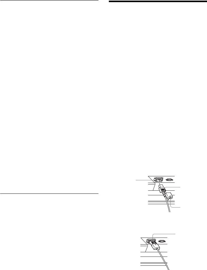
Connecting the AC Power Cord
1 Plug the AC power cord into the AC IN socket. Then, attach the AC plug holder (supplied) to the AC power cord.
AC IN socket
AC power cord |
AC plug holder
2 Slide the AC plug holder over the cord until it connects to the AC IN socket cover.
AC IN socket cover
15 (GB)
 Loading...