


H-MECH

VHS MECHANICAL ADJUSTMENT MANUAL IV
H MECHANISM
SERVICE MANUAL
SUPPLEMENT-3
File this supplement with the VHS mechanical adjustment IV and supplement-1, 2.
Subject: Mechanism chassis assembly changed.
PAL alignment tape changed.
(SL-600060)
TABLE OF CONTENTS
Section Title Page
1. MODIFICATION ............................................................ 2
1-1. Parts Requiring Cleaning ................................................. 2
1-2. Drum Assembly, Drum Base ............................................ 3
1-3. TG2 Roller, FE Head Assembly ....................................... 4
1-4. TG3, TG6 Guide Roller Assemblies................................. 5
1-5. Shuttle T Block and Loading Gear T Block
Assemblies ....................................................................... 6
1-6. Shuttle S Block and Loading Gear S Block
Assemblies ....................................................................... 7
2. ADJUSTING THE MECHANISM USING NEW
ALIGNMENT TAPE (KRV-52PL for PAL) .................. 8
2-1. Height Adjustment of Guide Rollers No. 3 and No. 6....... 8
2-2. ACE Head Assembly Adjustment
(Rough Adjustment) ......................................................... 9
2-3. ACE Head Assembly Adjustment
(Precision Adjustment) ..................................................... 9
2-4. X-Value Adjustment.......................................................... 10
2-5. Adjustments After Replacing the Drum
(Video Head) .................................................................... 14
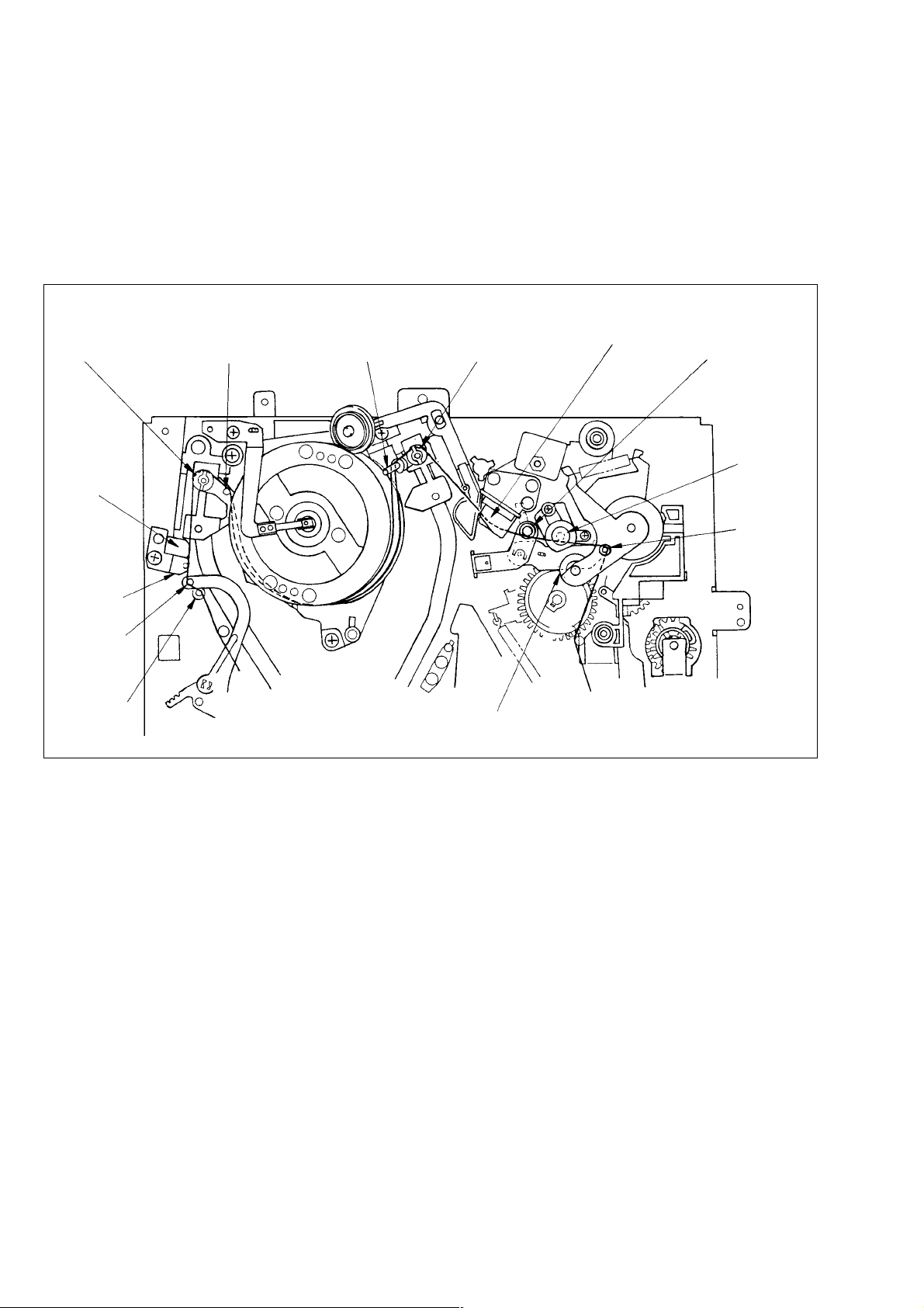
1. MODIFICATION
1-1. PARTS REQUIRING CLEANING
(Refer to VHS Mechanical Adjustment
Manual IV page 7)
• Parts requiring a cleaning were changed in shape, and therefore, Fig. 2-1 for new type is added.
!: Modificated portion
No. 3 guide
(TG3)
FE head
%
No. 2 guide
(TG2)
No. 1 guide
(TG1)
No. 0 guide
(TG0)
^
No. 4 guide
(TG4)
No. 5 guide
(TG5)
No. 6 guide
(TG6)
Pinch roller
^
ACE head No. 7 guide
(TG7)
Capstan
shaft
No. 8 guide
(TG8)
Fig. 2-1 Parts Requiring Cleaning
– 2 –
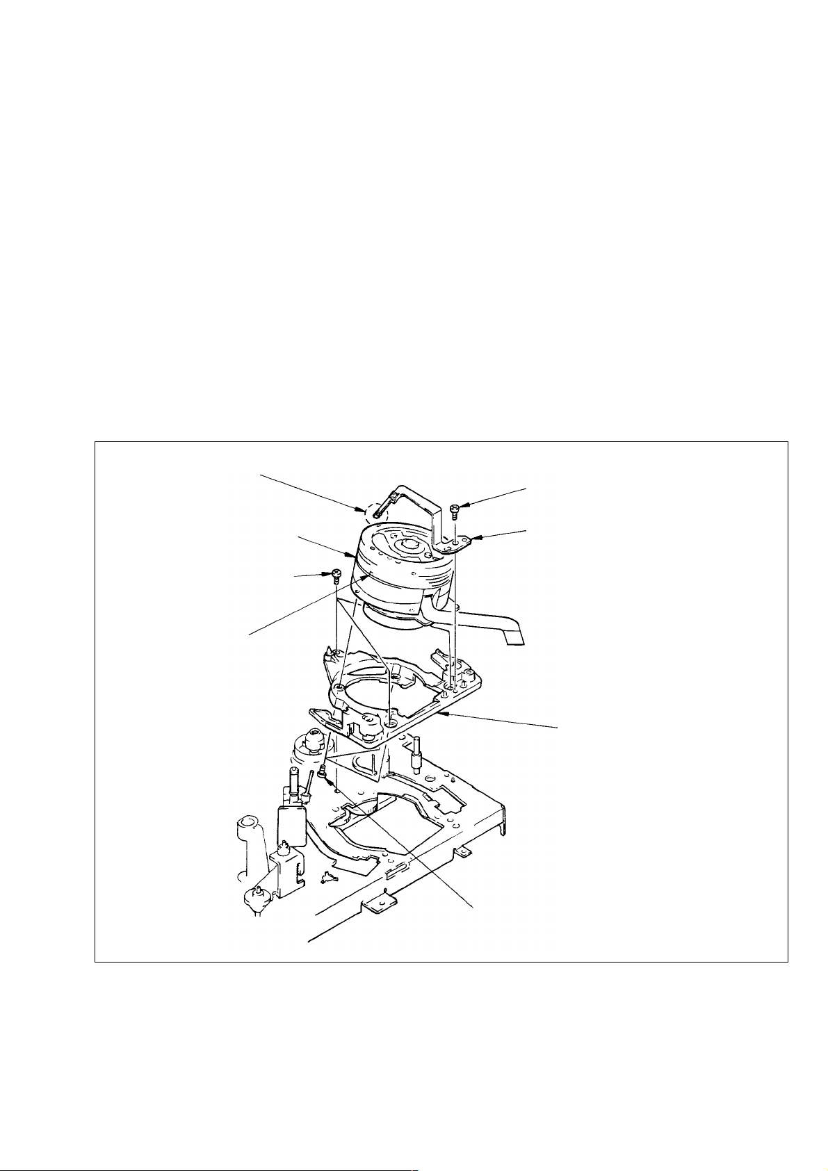
1-2. DRUM ASSEMBLY, DRUM BASE
(Refer to VHS Mechanical Adjustment
Manual IV page 11)
• The ground shaft assembly was changed and the drum base was
added, and therefore Section 3-2 for new type is added.
3-2. DRUM ASSEMBLY, DRUM BASE
(Fig. 3-2)
1) Remove screw 1.
2) Remove ground shaft assembly 2 not to touch its tip with
bare hand or tools.
3) Remove screws 3 to remove drum assembly 4.
4) Remove screws 5 to remove drum base 6.
[Note on Mounting]
• Don’t touch head chips and ground shaft assembly 4 with bare
hand or tools.
• Keep clean the surface contacts tape of drum assembly 4.
[Adjustment after Mounting]
• 4-1. Tape path adjustment.
Note: Don’t touch with bear hand or tools.
1 Screw (BV3 × 8)
4 Drum assembly
5 Screws
Head chips
Note: Don’t touch
with bare hand
or tools.
2 Ground shaft assembly
Note: Some models are not mounted.
6 Drum base
3 Screws (BV3 × 8)
Fig. 3-2
– 3 –
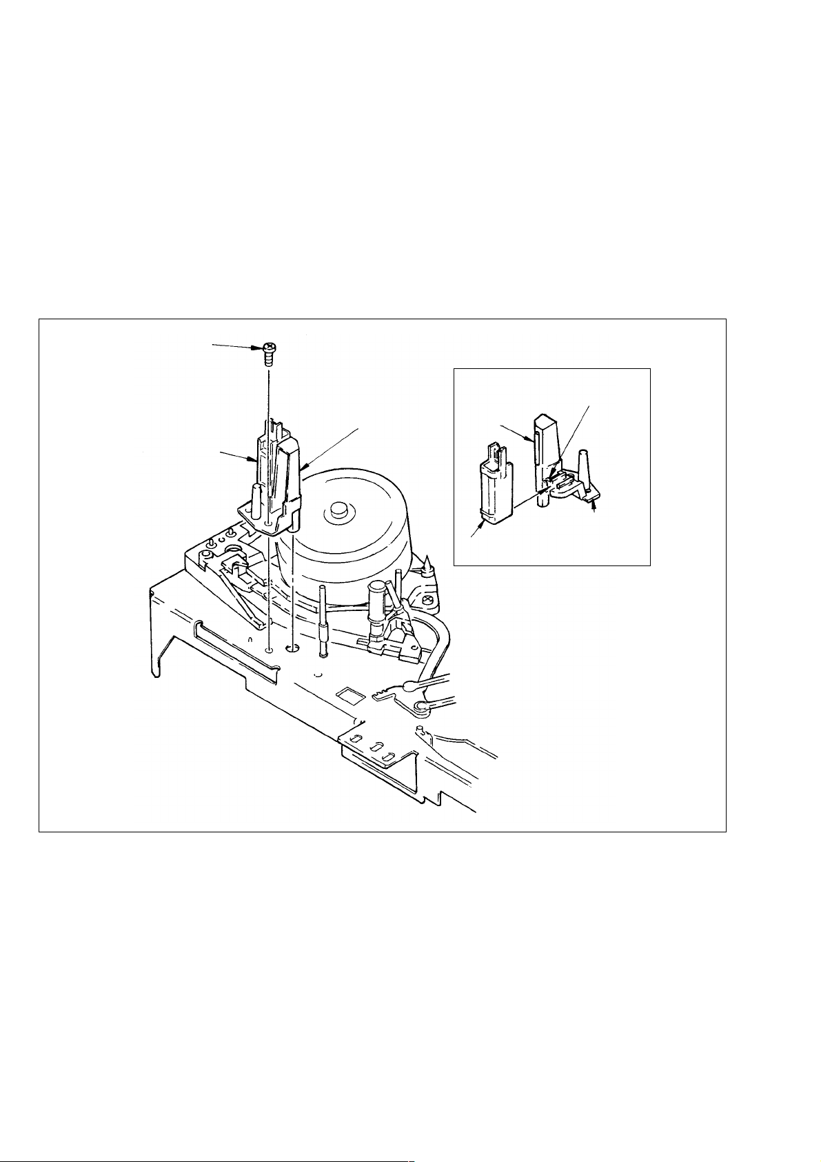
1-3. TG2 ROLLER, FE HEAD ASSEMBLY
(Refer to VHS Mechanical Adjustment
Manual IV page 14)
• The TG2 roller was assembled in the FE head assembly, and
therefore Section 3-5 for new type is added.
3-5. TG2 ROLLER, FE HEAD ASSEMBLY
(Fig. 3-5)
1) Remove screw 1.
2) Pull out FE head assembly 2.
[Note on Mounting]
• Keep clean the surface contacts tape of TG2 roller.
1 Screw (BV3 × 8)
2 FE head assembly
TG2 roller
After sliding, check
claw locks FE head.
TG2 roller
Fig. 3-5
FE head
FEH holder
Slide FE head onto
FEH holder.
Fig. A
– 4 –
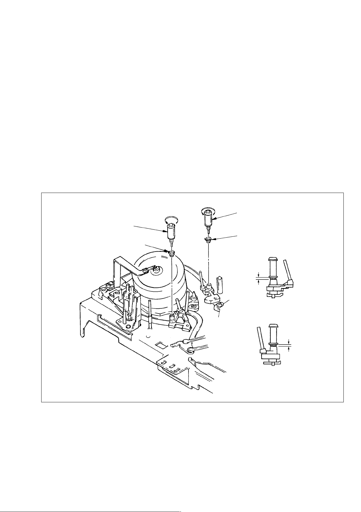
1-4. TG3, TG6 GUIDE ROLLER ASSEMBLIES
(Refer to VHS Mechanical Adjustment
Manual IV page 17)
• The TG3 and TG6 guide roller assemblies were changed, and
therefore Section 3-8 for new type is added.
3-8. TG3, TG6 GUIDE ROLLER ASSEMBLIES
(Fig. 3-8)
1) TG3 guide roller assembly 1 by turning it in the arrow A
direction.
2) Removal the spring 2.
3) TG6 guide roller assembly 3 by turning it in the arrow B
direction.
4) Removal the spring 4.
[Note on Mounting]
• Keep clean the surface contacts tape of TG3 and TG6 guide
roller assemblies 1, 3.
[Adjustment after Mounting]
• 4-1. Tape path adjustment.
A
B
3 TG6 guide rollser assembly
1 TG3 guide roller assembly
2 Spring
4 Spring
1.4 mm
TG3 guide roller assembly
Fig. A
1.4 mm
TG6 guide roller assembly
Fig. B
Fig. 3-8
– 5 –
 Loading...