


CDP-CX200
Table of contents
 Loading...
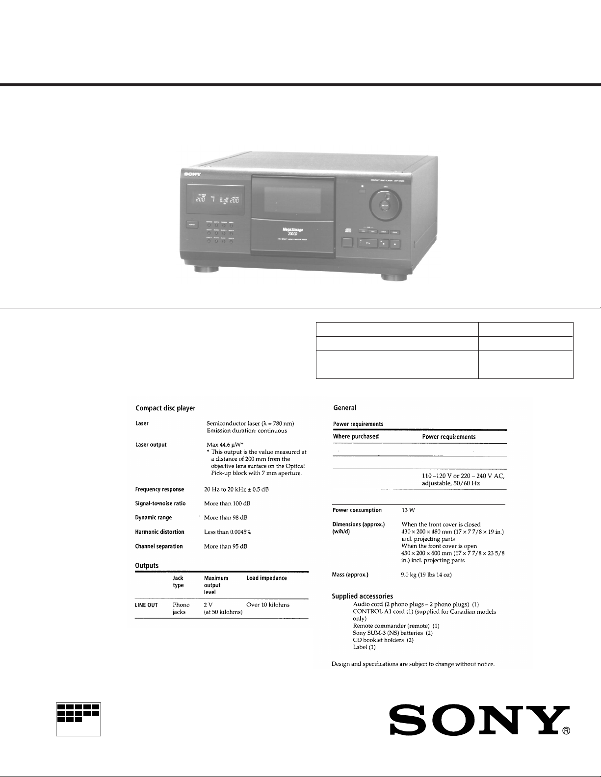
CDP-CX200
SERVICE MANUAL
Model Name Using Similar Mechanism NEW
CD Mechanism Type CDM-40
Base Unit Type KSM-213BKN/M-N
Optical Pick-up Type KSS-213B/S-N
SPECIFICATIONS
US Model
Canadian Model
AEP Model
UK Model
E Model
Australian Model
PX Model
MICROFILM
USA, Canada
Europe and Singapore
E, PX
Australia
COMPACT DISC PLAYER
120V AC, 60Hz
220V - 230V AC, 50Hz
240V AC, 50Hz
— 1 —
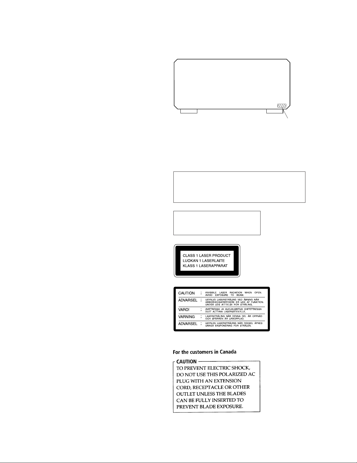
TABLE OF CONTENTS
1. SERVICING NOTE ........................................................... 3
2. GENERAL ....................................................................4
3. DISASSEMBLY
3-1. Front Panel Assembly ......................................................... 9
3-2. Back Panel Assembly ......................................................... 9
3-3. T able Assembly ................................................................10
3-4. Mechanism Deck Assembly ............................................. 10
3-5. Base Unit Assembly ......................................................... 11
4. TEST MODE ............................................................... 12
5. ADJUSTMENTS
5-1. Mechanical Adjsument ..................................................... 13
5-2. Electrical Block Checking................................................ 19
MODEL IDENTIFICATION
— BACK PANEL —
4-982-790-
US Model : 0π
Canadian Model : 1π
AEP,German Model : 2π
UK Model : 3π
E,PX Model : 4π
Singapore Model : 5π
Austrarian Model : 6π
6. DIAGRAMS
6-1. Circuit Boards Location ...................................................21
6-2. IC Pin Function
• IC101 Digital Servo, Digital Signal Processor
(CXD2545Q) ................................................................ 22
• IC303 System Control (CXP84332-Q28Q) .................25
6-3. Block Diagram ................................................................. 27
6-4. Printed Wiring Board — BD, DISP Section — ............... 31
6-5. Schematic Diagram — BD, DISP Section — .................. 35
6-6. Printed Wiring Board — MAIN Section — .....................39
6-7. Schematic Diagram — MAIN Section —........................43
6-8. IC Block Diagrams ........................................................... 47
7. EXPLODED VIEWS
7-1. Case and Back Panel Section ...........................................50
7-2. Disc Table Section ............................................................51
7-3. Front Panel Section .......................................................... 52
7-4. Mechanism Section-1 (CDM-40) ..................................... 53
7-5. Mechanism Section-2 (CDM-40) ..................................... 54
7-6. Base Unit Section-1 (KSM-213BKN/M-N).....................55
7-7. Base Unit Section-2 (KSM-213BKN/M-N).....................56
8. ELECTRICAL PARTS LIST ........................................ 57
Notes on chip component replacement
• Never reuse a disconnected chip component.
• Notice that the minus side of a tantalum capacitor may be
damaged by heat.
CAUTION
Use of controls or adjustments or performance of procedures
other than those specified herein may result in hazardous radiation exposure.
The laser component in this product
is capable of emitting radiation
exceeding the limit for Class 1.
This appliance is classified as
a CLASS 1 LASER product.
The CLASS 1 LASER
PRODUCT MARKING is
located on the rear exterior.
This caution label
is located inside
the unit.
Flexible Circuit Board Repairing
• Keep the temperature of soldering iron around 270˚C
during repairing.
• Do not touch the soldering iron on the same conductor of the
circuit board (within 3 times).
• Be careful not to apply force on the conductor when soldering
or unsoldering.
— 2 —
SECTION 1
SERVICING NOTE
SAFETY CHECK-OUT
(US model only)
After correcting the original service problem, perform the following safety checks before releasing the set to the customer:
Check the antenna terminals, metal trim, “metallized” knobs, screws,
and all other exposed metal parts for AC leakage. Check leakage as
described below.
LEAKAGE
The AC leakage from any exposed metal part to earth Ground and
from all exposed metal parts to any exposed metal part having a
return to chassis, must not exceed 0.5 mA (500 microampers). Leakage current can be measured by any one of three methods.
1. A commercial leakage tester, such as the Simpson 229 or RCA
WT-540A. Follow the manufacturers’ instructions to use these
instruments.
2. A battery-operated AC milliammeter. The Data Precision 245
digital multimeter is suitable for this job.
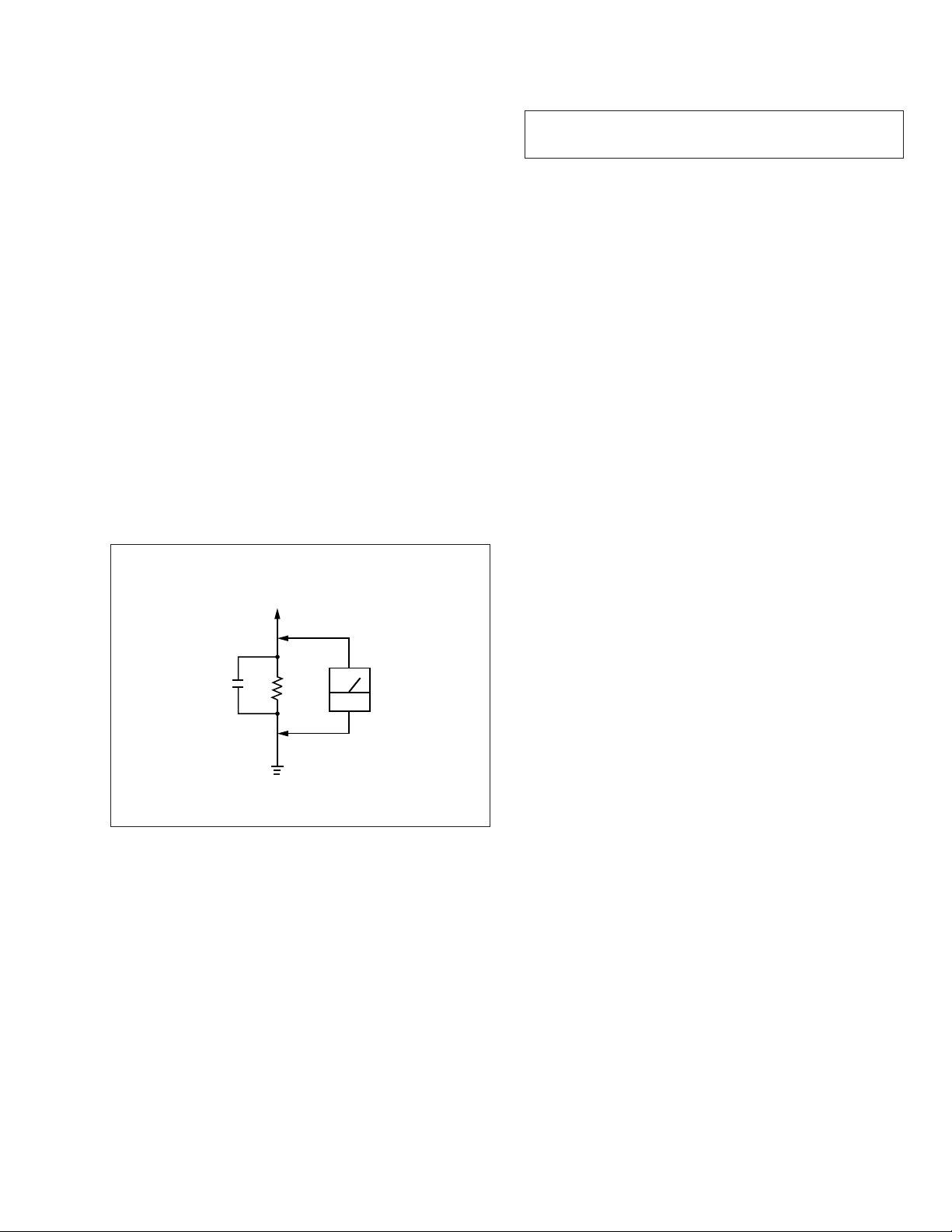
3. Measuring the voltage drop across a resistor by means of a VOM
or battery-operated AC voltmeter. The “limit” indication is 0.75
V, so analog meters must have an accurate low-volta ge scale.
The Simpson 250 and Sanwa SH-63Trd are examples of a passive VOM that is suitable. Nearly all battery operated digital
multimeters that have a 2V AC range are suitable. (See Fig. A)
NOTES ON HANDLING THE OPTICAL PICK-UP BLOCK
OR BASE UNIT
The laser diode in the optical pick-up block may suffer electrostatic
breakdown because of the potential difference generated by the
charged electrostatic load, etc. on clothing and the human body.
During repair, pay attention to electrostatic breakdown and also use
the procedure in the printed matter which is included in the repair
parts.
The flexible board is easily damaged and should be handled with
care.
NOTES ON LASER DIODE EMISSION CHECK
The laser beam on this model is concentrated so as to be focused on
the disc reflective surface by the objecti ve lens in the optical pick-up
block. Therefore, when checking the laser diode emission, observe
from more than 30 cm away from the objective lens.
LASER DIODE AND FOCUS SEARCH OPERA TION CHECK
Carry out the “S curve check” in “CD section adjustment” and check
that the S curve waveform is output repeatedly.
To Exposed Metal
Parts on Set
0.15µF
1.5k
Ω
Earth Ground
AC
voltmeter
(0.75V)
Fig. A. Using an AC voltmeter to check AC leakage.
SAFETY-RELATED COMPONENT WARNING !!
COMPONENTS IDENTIFIED BY MARK ! OR DO TTED LINE
WITH MARK ! ON THE SCHEMATIC DIAGRAMS AND IN
THE PARTS LIST ARE CRITICAL TO SAFE OPERATION.
REPLACE THESE COMPONENTS WITH SONY PARTS
WHOSE PART NUMBERS APPEAR AS SHOWN IN THIS
MANUAL OR IN SUPPLEMENTS PUBLISHED BY SONY.
ATTENTION AU COMPOSANT AYANT RAPPORT
À LA SÉCURITÉ!!
LES COMPOSANTS IDENTIFIÉS P AR UNE MARQUE ! SUR
LES DIAGRAMMES SCHÉMATIQUES ET LA LISTE DES
PIÈCES SONT CRITIQUES POUR LA SÉCURITÉ DE
FONCTIONNEMENT. NE REMPLACER CES COMPOSANTS
QUE PAR DES PIÈCES SONY DONT LES NUMÉROS
SONT DONNÉS DANS CE MANUEL OU DANS LES
SUPPLÉMENTS PUBLIÉS PAR SONY.
— 3 —
LOCATION OF PARTS AND CONTROLS
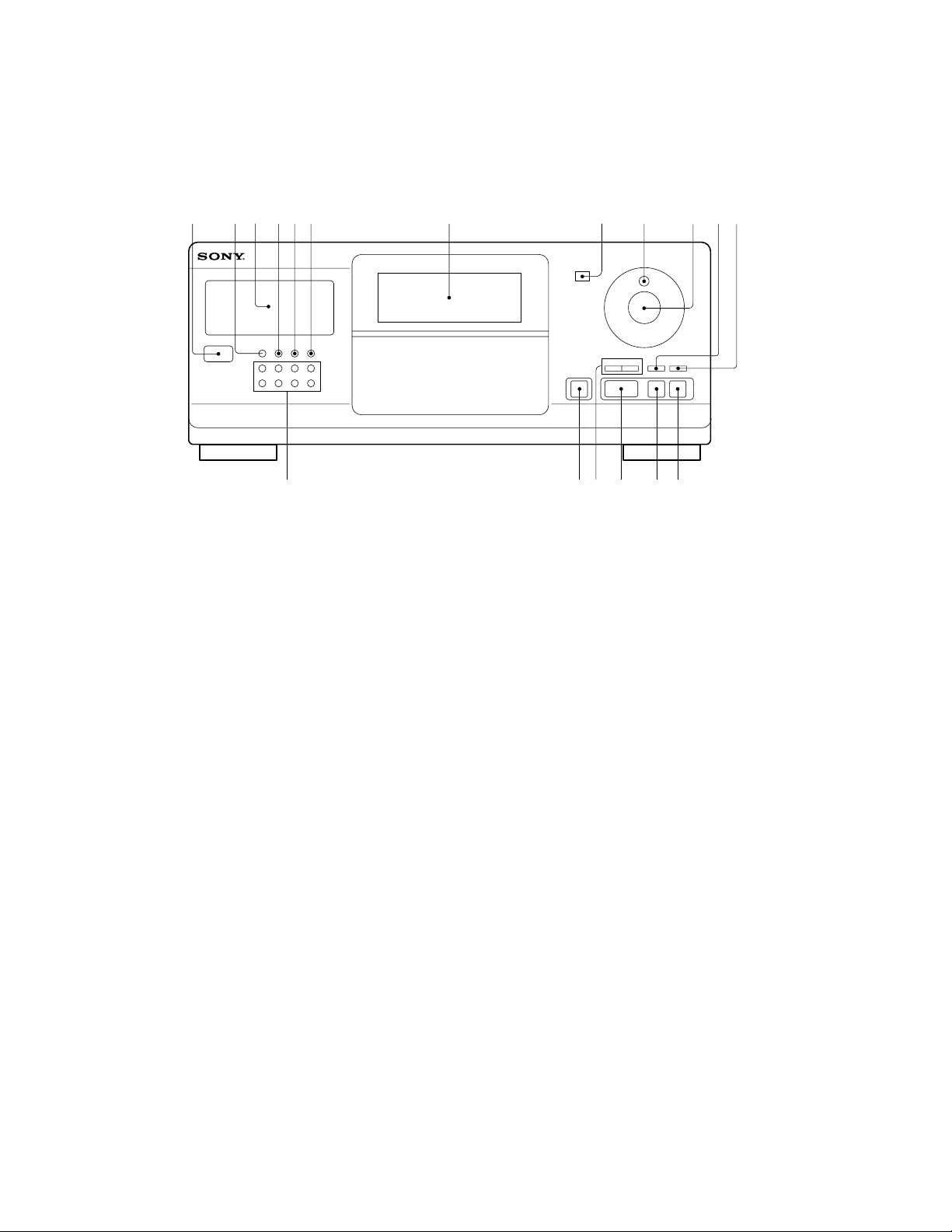
Front Panel
SECTION 2
GENERAL
1 POWER button
2 CONTINUE button
3 Display window
4 SHUFFLE button
5 PROGRAM button
6 REPEAT button
7 Front cover
8 Remote sensor
9 JOG dial
!º ENTER button
12
3
5
4
!•
6
7
!§!¶
!¡ CHECK button
!™ CLEAR button
!£ p (stop) button
!¢ P (pause) button
!∞ · (play) button
!§ ≠ AMS* ± button
!¶ OPEN button
!• BLOCK 1-8 buttons
* AMS is the abbreviation for Automatic Music Sensor.
98!º!¡
!¢
!∞
!£
!™
— 4 —
This section is extracted from
instruction manual.
— 5 —
PX
— 6 —
— 7 —
— 8 —

SECTION 3
DISASSEMBLY
Note : Follow the disassembly procedure in the numerical order given.
3-1. FRONT PANEL ASSEMBLY
6
Remove the claw
1
Two screws
(BVTP 3x8)
7
Front panel assembly
5
Remove the claw
4
Flat type wire (CN601)
3-2. BACK PANEL ASSEMBLY
5
Remove the PC board holder
6
Back panel
3
Two screws (BVTT 3x6)
2
Three screws (BVTT 3x6)
1
Connector
(CN501)
2
Four screws (BVTT 3x6)
4
Screw
(BVTP3x10)
— 9 —
3
Five screws
(BVTT3x6)
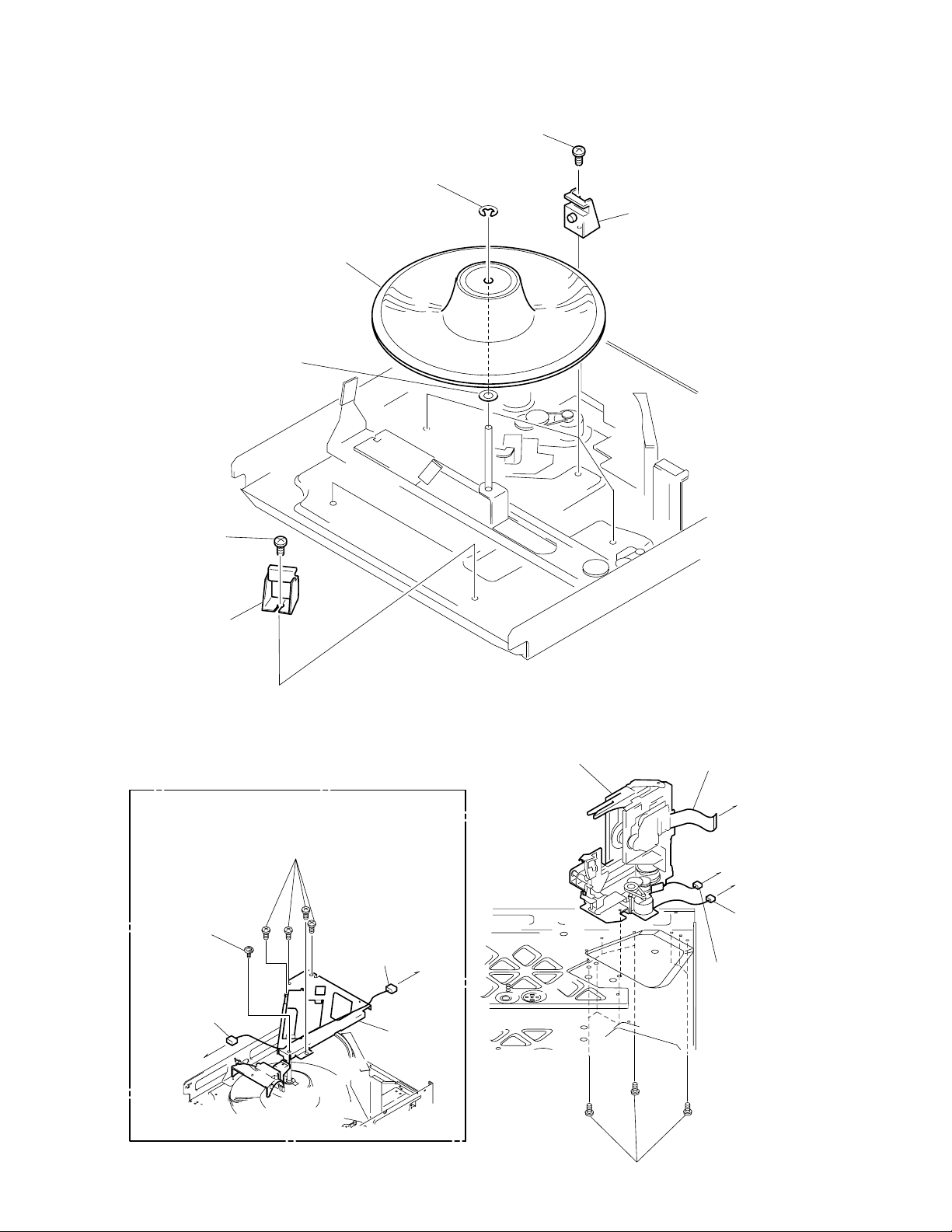
3-3. T ABLE ASSEMBLY
2
Two screws
(BVTT3x6)
7
Washer
1
Stop ring (E type)
6
Table assembly
4
Three screws (BVTT3x6)
5
Three holder assemblies
3
Two holder assemblies
3-4. MECHANISM DECK ASSEMBLY
1
Four screws (BVTT3x6)
2
Screw
(BVTT3x6)
3
Connector
(CN303)
Illumination
board
4
Connector
(CN308)
5
Guide
assembly
Jack
board
!º
Mechanism deck
6
Flat type wire
(23core) (CN303)
Jack board
8
Connector (CN504)
Main board
Main board
7
Connector
(CN304)
— 10 —
9
Nine screws (BVTT3x8)
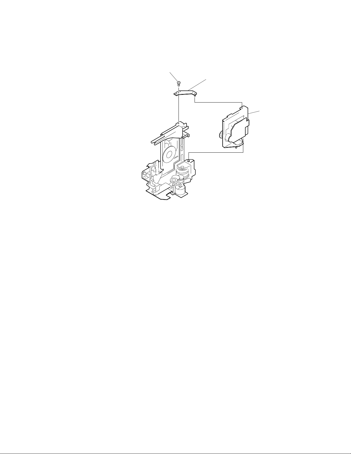
3-5. BASE UNIT ASSEMBLY
1
Screw (BVTT3x6)
2
Fulcrum plate
(BU UPPER) assy
3
Base unit
— 11 —

SECTION 4
TEST MODE
4-1. Display Check Mode
With the pow er turned off (standby state), press the POWER button
while pressing the P (pause) button.
All FL segments and grids light up together with the · (play), P
(pause), and standby LEDs.
At the same time, the GROUP LEDs are scanned one by one.
Note: To exit this mode, press the POWER button.
4-2. ADJ Mode
1. Turn ON the power of the unit, set disc to disc table, and perform
chucking.
2. Disconnect the power supply plug from the outlet.
3. T o set ADJ mode, connect the test point (TP301:ADJ) of the MAIN
board to Ground, and turn on the power supply plug to the outlet.
The power will turn on automatically , and the first track will be played.
In this mode, table rotation and loading operations are not performed
because it is taken that the disc has already been chucked.
Note: The same operations are also performed in the following when
the test point (TP301:ADJ) is connected to Ground after turning on the power.
• Direct search (movement of sledding motor) is not performed dur-
ing accessing
• Ignored even when GFS becomes L
• Ignored even when the Q data cannot be read
• Focus gain does not decrease
• Spindle gain does not decrease
• Servo related settings can be set manually and checked (Refer to
ADJ Mode Special Functions Table)
ADJ Mode Special Functions Table
(The buttons shown with ( ) function by using the supplied remote commander only)
Button
CONTINUE
SHUFFLE
PROGRAM
BLOCK 1 (1)
BLOCK 2 (2)
BLOCK 3 (3)
BLOCK 4 (4)
BLOCK 5 (5)
BLOCK 6 (6)
BLOCK 7 (7)
BLOCK 8 (8)
(9)
(10/0)
CHECK
CLEAR
Servo average display
Displays VC, FE, RF, TE and traverse in hexadecimal
numbers
Focus bias display
Each time this is pressed, the focus bias is switched
between 1 and 2
(1)
Bias actually set Optimum bias Minimum jitter
(2)
U:Upper aliasing bias L:Lower aliasing bias
Auto gain display
Displays focus, tracking, sledding in hexadecimal
numbers
Increases the focus bias in 8 steps.
Sets the focus bias in the middle of aliasing.
Turns off the tracking and sledding servo
Returns the auto gain to the initial value (30)
Turns off the focus servo
Decreases the focus bias in 8 steps.
Re-adjusts the focus bias
Turns on the tracking and sledding servo
Switches the focus servo gain between normal and down
08: normal, 0C: down
Sets the focus bias to 0 (no bias)
Next, displays the jitter measured at the focus bias set
S-curve observation mode
Automatic eccentric measurement
The results of measurement is displayed in µm directly.
Function
4-3. Key and Display Check Mode
To set this mode, connect the test point (TP302:AF ADJ) on the MAIN
board to Ground, and turn on the power supply plug to the outlet.
• All FL segments and grids will light up. (All lit check)
When a button is pressed, the types of buttons pressed until then
will be displayed on the left side and the number of the buttons will
be displayed on the right side. However , these will not be displayed
for the following special buttons.
p(stop) button: FL segment check
(Refer to FL Tube Check Patterns)
P(pause) button: FL grid check (Refer to FL Tube Check P atterns)
The pause LED also lights up simultaneously.
·(play) button: All FL segment and grid will light up
The play LED also lights up simultaneously.
FL Tube Check Patterns
Segment check
2
1
Grid check
PROGRAM
REPEAT 1
• When the jog dial is rotated to the right, the Block indicators of FL
light up in the order of 1n2..8n1.
• When the jog dial is rotated to the left, the Block indicators of FL
light up in the order of 8n7..1n8.
• The standby LED lights up when the door switch is shut.
• Abbreviation
FL: Fluorescent Indicator Tube
[ MAIN BOARD ] — Component Side —
IC303
R311
TP302
AFADJ
IC307
R337
TP301
ADJ
R310
IC301
REMOTE
— 12 —
SECTION 5
ADJUSTMENTS
5-1. MECHANICAL ADJUSTMENT
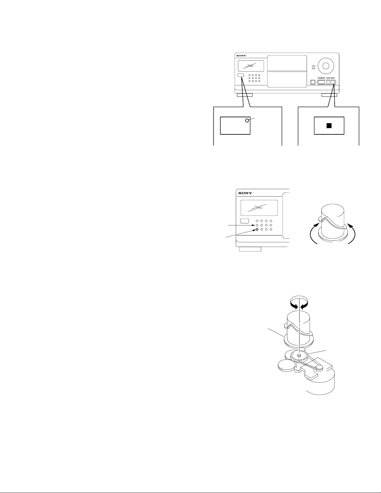
Perform the following steps before carrying out adjustments.
1. Turn ON the power of the unit, set disc to disc table No. 92, and
perform chucking.
2. Turn OFF the power.
3. Remove the case.
4. While pressing the STOP button, turn ON the POWER button.
The test mode is set.
5. The POWER button LED starts blinking.
(Test mode)
LED
POWER
NOTE 1: The cam will start rotating when the BLOCK 1 or BLOCK
5 button is pressed continuously in the test mode.
POWER button
BLOCK 1
button
BLOCK 5
button
STOP button
BLOCK 1 button
BLOCK 5 button
NOTE 2: If the power cannot be supplied, the cam can be rotated by
rotating the pulley with your finger.
Cam
Pulley
— 13 —
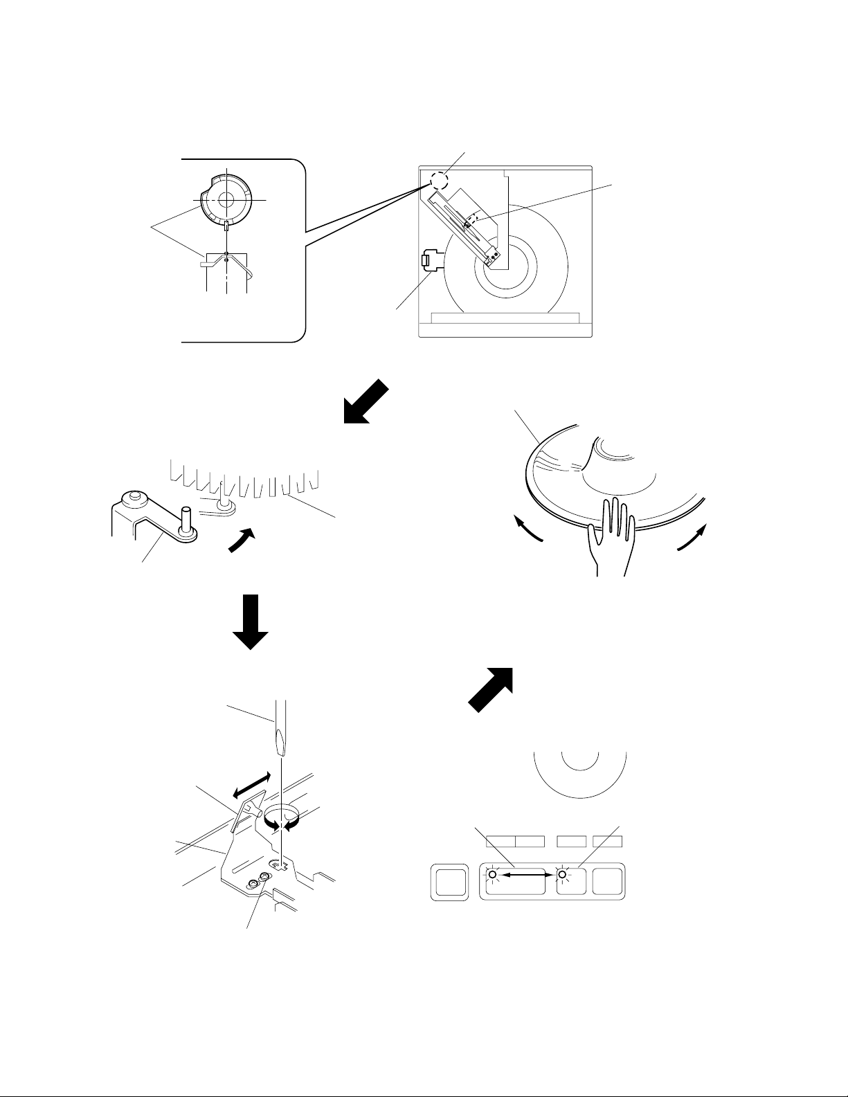
SENSOR ALIGNMENT
If the disc table swings to the left and right just before the disc is
chucked, perform the following adjustment.
Cam
Cam
LEVER (stopper)
assembly
(1) Rotate the cam and adjust to the position
shown in the figure.
(2)Check that the lever (stopper) assem-
bly secures the disc table as shown in
the figure.
Lever (stopper) assembly
Tepering screwdriver
Bracket (sensor)
Table assembly
Disc table
Swing
(4)Moving the disc table right and left with a hand after the screw is
fixed, the table will move by the play of a disc table. If the LEDs
light up alternately, the adjustment will be performed correctly)
Luminus board
PLAY button
Bracket (sensor)
Fixed screw
PAUSE button
(3)Loosen the fixed screw by 60° to 90°, and use a tapering screwdriver to adjust the screw as shown in the figure.
Move the bracket (sensor) with the tapering screwdriver little by little, and fix the fixed at where the paly botton's LED (green) is switched to
the pause button's LED (orange) (or its reverse).
— 14 —

GUIDE (DISC T) ALIGNMENT
Cam
(1)Rotate the cam and adjust to the position
shown in the figure.
Guide (disc T)
(2)Check that the state is as shown in the
figure.
Guide (disc T)
Cam
Holder (guide T)
Fixed screw
Guide (disc T)
Disc
(3)Loosen the fixed screw by about 60 °.
Disc
A
B
Holder
(guide T)
(4)Move the holder (guide T) with a tapering screwdr iver, and
set the position of the guide (disc T) to A:B=1:1.
Tapering screwdriver
Holder (guide T)
— 15 —
Loading...