


COLOR VIDEO CAMERA
BVP-E30 series
You can find the Operation Manuals in Japanese, English, French, German, Italian and Spanish on the CD-ROM (packed together).
For details on the manuals supplied, see “Using the CD-ROM Manual” on page 4.
OPERATION MANUAL [English] 1st Edition

WARNING
To prevent fire or shock hazard, do not expose the unit to rain or moisture.
To avoid electrical shock, do not open the cabinet. Refer servicing to qualified personnel only.
For the customers in the USA
This equipment has been tested and found to comply with the limits for a Class A digital device, pursuant to Part 15 of the FCC Rules. These limits are designed to provide reasonable protection against harmful interference when the equipment is operated in a commercial environment. This equipment generates, uses, and can radiate radio frequency energy and, if not installed and used in accordance with the instruction manual, may cause harmful interference to radio communications. Operation of this equipment in a residential area is likely to cause harmful interference in which case the user will be required to correct the interference at his own expense.
You are cautioned that any changes or modifications not expressly approved in this manual could void your authority to operate this equipment.
The shielded interface cable recommended in this manual must be used with this equipment in order to comply with the limits for a digital device pursuant to Subpart B of Part 15 of FCC Rules.
For the customers in Europe
This product with the CE marking complies with the EMC Directive (89/336/EEC) issued by the Commission of the European Community.
Compliance with this directive implies conformity to the following European standards:
•EN55103-1: Electromagnetic Interference (Emission)
•EN55103-2: Electromagnetic Susceptibility (Immunity) This product is intended for use in the following Electromagnetic Environment(s):
E1 (residential), E2 (commercial and light industrial),
E3 (urban outdoors) and E4 (controlled EMC environment, ex. TV studio).
Pour les clients européens
Ce produit portant la marque CE est conforme à la Directive sur la compatibilité électromagnétique (EMC) (89/336/CEE) émise par la Commission de la Communauté européenne.
La conformité à cette directive implique la conformité aux normes européennes suivantes :
EN55103-1: Interférences él ectromagnétiques (émission) EN55103-2: Sensibilité électromagnétique (immunité)
Ce produit est prévu pour être utilisé dans les environnements électromagnétiques suivants:
E1 (résidentiel), E2 (commercial et industrie légère), E3 (urbain extérieur) et E4 (environnement EMC contrôlé, ex. studio de télévision).
Für Kunden in Europa
Dieses Produkt besitzt die CE-Kennzeichnung und erfüllt die EMV-Richtlinie (89/336/EWG) der EG-Kommission. Angewandte Normen:
•EN55103-1: Elektromagnetische Verträglichkeit (Störaussendung)
•EN55103-2: Elektromagnetische Verträglichkeit (Störfestigkeit),
für die folgenden elektromagnetischen Umgebungen: E1 (Wohnbereich), E2 (kommerzieller und in beschränktem Maße industrieller Bereich), E3 (Stadtbereich im Freien) und E4 (kontrollierter EMV-Bereich, z.B. Fernsehstudio)
Voor de Klanten in Nederland
Gooi de batterij niet weg, maar lever hem in als KCA.
Note on laser beams
Laser beams may damage the CCDs. If you shoot a scene that includes a laser beam, be careful not to let a laser beam become directed into the lens of the camera.
2

Table of Contents
Using the CD-ROM Manual .................................................. |
4 |
CD-ROM System Requirements ............................................... |
4 |
Preparations ............................................................................... |
4 |
Reading the CD-ROM Manual .................................................. |
4 |
Overview ............................................................................... |
5 |
Features...................................................................................... |
5 |
Optional Accessories ................................................................ |
7 |
Location and Function of Parts........................................... |
8 |
Side Panels................................................................................ |
8 |
Front Panel............................................................................... |
10 |
Setting Up the Camera ....................................................... |
12 |
Attaching a Lens to the Camera............................................... |
12 |
Attaching a 1.5-type/2-type Viewfinder .................................. |
13 |
Attaching the Camera Adaptor or Wireless Camera |
|
Transmitter ..................................................................... |
15 |
Adjusting the Shoulder Pad Position ....................................... |
16 |
Mounting the Camera to a Tripod ........................................... |
17 |
Using a Memory Stick ........................................................ |
18 |
Notes on Memory Stick ........................................................... |
18 |
Display on the Viewfinder Screen..................................... |
20 |
Menu Operation .................................................................. |
21 |
Displaying the Menu................................................................ |
21 |
Displaying the TOP MENU..................................................... |
21 |
Selecting a Menu Page From the CONTENTS Screen ........... |
21 |
Setting the Menu...................................................................... |
21 |
Using the USER Menu ............................................................ |
22 |
MENU Items........................................................................... |
25 |
Specifications ..................................................................... |
33 |
Table of Contents |
3 |
|
|

Using the CD-ROM
Manual
The supplied CD-ROM includes versions of the Operation Manual for the BVP-E30 series (Japanese, English, French, German, Italian, and Spanish versions).
CD-ROM System Requirements
The following are required to access the supplied CDROM disc.
•Computer: PC with Intel Pentium CPU
–Installed memory: 64 MB or more
–CD-ROM drive: ×8 or faster
•Monitor: Monitor supporting resolution of 800 × 600 or higher
•Operating system: Microsoft Windows Millennium Edition, Windows 2000 Service Pack 2, Windows XP Professional or Windows XP Home Edition
When these requirements are not met, access to the CDROM disc may be slow, or not possible at all.
Preparations
One of the following programs must be installed on your computer in order to use the operation manuals contained on the CD-ROM disc.
•Adobe Acrobat Reader Version 4.0 or higher
•Adobe Reader Version 6.0 or higher
Note
If Adobe Reader is not installed, you can download it from the following URL:
http://www.adobe.com/
Reading the CD-ROM Manual
To read the operation manual contained on the CD-ROM disc, do the following:
1 Insert the CD-ROM disc in your CD-ROM drive.
A cover page appears automatically in your browser. If it does not appear automatically in the browser, double-click the index.htm file on the CD-ROM disc.
2 Select and click the operation manual that you want to read.
This opens the PDF file of the operation manual.
Note
If you lose the CD-ROM disc or become unable to read its content, for example because of a hardware failure, you can do one of the following:
•You can purchase a new CD-ROM disc to replace one that has been lost or damaged. Contact your Sony service representative.
•You can purchase printed versions of the operation manuals. Contact your Sony service representative. When ordering, be sure to specify the part number of the manual you want.
–3-854-246-0x (Japanese version for NTSC models only)
–3-854-247-0x (English version)
–3-854-248-0x (French version)
–3-854-249-0x (German version)
–3-854-250-0x (Italian version)
–3-854-251-0x (Spanish version)
•Intel and Pentium are registered trademarks of Intel Corporation
or its subsidiaries in the United States and other countries.
•Microsoft and Windows are registered trademarks of Microsoft Corporation in the United States and/or other countries.
•Adobe, Acrobat, and Adobe Reader are trademarks of Adobe Systems Incorporated in the United States and/or other countries.
4 Using the CD-ROM Manual

Overview
The BVP-E30-series Color Video Camera is a digital portable camera with functions and performance suitable for use in a studio as well as for outside broadcast applications. The BVP-E30 (NTSC model) and BVPE30P (PAL model) are designed only for the aspect ratio 4:3. With the BVP-E30WS (NTSC model) and BVPE30WSP (PAL model), the aspect ratio is switchable between 4:3 and 16:9.
By using the BVP-E30-series camera with a camera adaptor (CA), camera control unit (CCU), video selector (VCS), master setup unit (MSU), remote control panel (RCP), etc., a wide variety of systems from a basic to a large system can be configured for your special purposes. While based on Sony's long-cultivated technologies for the BVP-series camera for broadcasting use, the BVP-E30- series camera is a new-generation camera with advanced performance, functions, and quality, achieved by adopting a Mega Pixel CCD, the newly developed 8-million-gate process LSI, and excellent circuit and mounting technologies.
Features
High quality
The newly developed Mega Pixel Power HAD EX CCD assures higher signal-to-noise ratio, higher sensitivity, broader dynamic range, and less smear. In addition, by adopting the double-density CCD, Progressive Scan (PsF) is also possible.
High S/N
A higher signal-to-noise ratio, –67 dB (typical) for NTSC, and –65 dB (typical) for PAL, has been achieved as a result of the newly adopted Power HAD EX CCD and excellent circuit and mounting technologies.
High sensitivity
A sensitivity of F11 at 2,000 lux (typical) has been achieved. When the video gain is raised by 42 dB, a video level of 100% is obtained with minimum subject illuminance of 0.25 lux.
Wide dynamic range
With 600% dynamic range assured, capabilities such as knee saturation and adaptive knee enable reproducing high-luminance subjects clearly.
Lower smear
Thanks to the Power HAD EX technology, the smear level has been largely improved by about 25 dB (compared with the Sony IT POWER HAD CCD) to –145 dB or less.
Progressive Scan (PsF)
By adopting the double-density CCD, Progressive Scan (PsF) is possible. Progressive Scan signals from the CCD are converted to and output as interlaced signals by the frame memory (Segment Frame system), thus enabling handling of a Progressive Scan system without changing the existing system.
Versatility, high reliability
Thanks to the newly developed 8-million-gate largeprocessing LSI using 0.18-micron processing technology, most of signal processing of camera is handled by a single chip, achieving a drastic reduction in power consumption, as well as variety of functions, higher picture quality, and higher reliability.
Cross-color suppression
A high-performance cross-color-suppression circuit built into this camera suppresses cross colors in composite video signals without degrading the resolution. As the circuit processes signals as RGB component signals, this function is also effective for CCU output and digital component output.
Low key saturation
Coloring in dark parts, in which colors are difficult to distinguish, can be controlled.
Selectable gamma curves
The gamma curve is selectable from among various options.
Digital encoder
The digitalized encoder circuits, converged into a single LSI chip, produce accurate and stable signal output.
2D-black-shading/3D-white-shading/dynamic- shading compensation functions
High-accuracy shading compensation for both dark and bright parts allows pictures with less shading. The dynamic-shading function is activated only when a lens allowing this function is attached.
Knee saturation/adaptive saturation
Greatly improved knee saturation and adaptive saturation enable reproducing high-luminance subjects clearly and gaining pictures with a wider dynamic range.
Electronic soft focus
Compared with the conventional detail compensation, which could only sharpen images, the electronic soft-focus
Overview 5

mechanism adopted in this camera also allows you to soften images.
Triple-skin-tone-detail control
Skin-tone detail correction that allows detail to be set independently for each of the three separate color ranges is provided. The combination of the skin-tone detail control and the above-mentioned electronic soft focus results in more effective detail compensation.
16-axis multimatrix hue control
Hue is divided into 16 blocks, and their phases and saturations can be controlled independently. Thus, subtle hue adjustment in cases where as hue adjustment is required among various cameras, can be easily made.
NAM V DTL (vertical detail generation mode)
Vertical detail signals are made for R, G, and B signals individually, and the largest signal among them is selected as the final V-detail signal. This method, compared with the conventional simple addition method, allows you to improve resolution with a highly saturated subject. The conventional V-detail generation method can also be selected, if necessary.
Slow-Shutter mode
By controlling CCD reading, shooting in Slow-Shutter mode of 7 frames at maximum is enabled.
Excellent operability
Memory Stick and file system
In addition to the conventional reference file, scene file, and lens file, the operator file is newly adopted. In the operator file, data such as switch settings of the camera and customized sets of menu selections are stored. File data are stored in the Memory Stick, and can be quickly called from it.
USER Menu and OPERATION Menu
The USER Menu, which allows you to place only menu items of your choice in any order, and the OPERATION Menu, which allows you to select items to be displayed in the viewfinder and to assign switch settings, are provided.
PAINT Menu and MAINTENANCE Menu
Adjustment and maintenance of the camera can be made by menu operation.
Assignable button and Handle buttons
To the Assignable button at the top of the side panel, any function among 5600K, ATW, and CROP (only for the BVP-E30WS/E30WSP) can be assigned.
To the two handle buttons located on the handle of the camera, any two functions among return video, intercom, and zoom control of the lens (only for lenses with zoom control function) can be assigned.
Electronic color-temperature conversion (5600K)
Color-temperature conversion at 5600K is electronically conducted. Thus, instead of an optical color-temperature conversion filter, the number of ND filters can be increased.
Full-servo optical-filter discs
A pair of motor-operated optical-filter discs are standard equipment with the BVP-E30/E30WS/E30WSP. This enables you to remotely control the camera from an MSU or RCP, facilitating system operation.
For the BVP-E30P, a single manual filter is provided.
6 Overview

Optional Accessories
The following optional accessories are available.
Overview 7

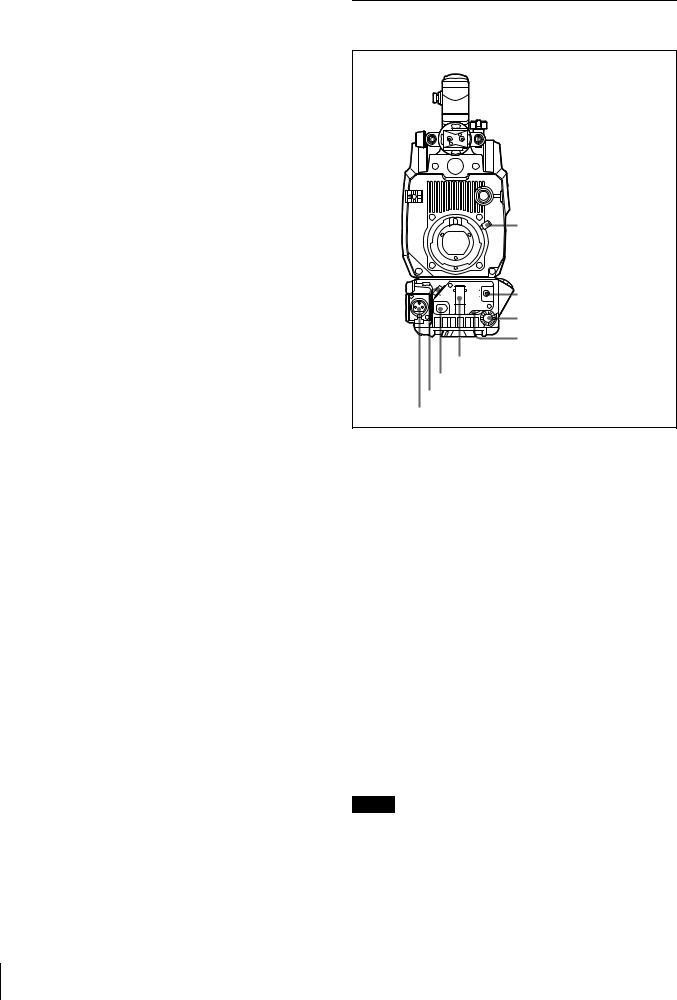
Location and Function of Parts
Side Panels
aHandle buttons
bViewfinder lock lever
cAssignable button
dND filter selector
eCC filter selector (BVPE30/E30WS/E30WSP only)
fWHITE BAL switch
gOUTPUT/DCC switch
hGAIN switch
iVTR switch
jSTATUS/CANCEL switch
kDISPLAY switch
RET1 |
INCOM |
BVP-E30P
dND filter selector 
lMemory Stick slot
VTR |
GAIN |
OUTPUT |
WHITE BAL |
|
STATUS |
ON |
|
|
|
OFF |
|
CANCEL |
MENU |
|
|
|
MENU |
DISPLAY |
|
GENLOCK
mShoulder pad lock lever nCA lock screw
oLOCK knob
pViewfinder lock ring
TESTOUT
MIC
qTEST OUT connector
8 Location and Function of Parts

a Handle buttons
The function of each of these buttons is assignable in the menu operation.
At the factory, the front-side button is set to RET 1, and the rear-side button is set to INCOM 1.
RET 1 (return video 1): A return video 1 signal from the Camera Control Unit (CCU) is displayed on the viewfinder screen while this button is pressed.
INCOM (intercom 1): The intercom microphone is ON while this button is pressed.
For details, see “Menu Operation” on page 21.
b Viewfinder lock lever
Locks the viewfinder after adjusting the position in the front-to-rear direction together with the LOCK knob.
c Assignable button
Desired function can be assigned to this button by the menu operation.
On the BVP-E30P, a color temperature conversion filter of 5600K is set for the button at the factory. The setting can be changed with the OPERATION Menu.
On the BVP-E30/E30WS/E30WSP, nothing is set. Set the function with the OPERATION Menu as required.
For details, see “Menu Operation” on page 21.
d ND filter selector
Selects the desired ND filter.
Filter No. |
Filter |
|
|
1 |
Clear |
|
|
2 |
1/4ND |
|
|
3 |
1/16ND |
|
|
4 |
1/64ND |
|
|
eCC (color temperature conversion) filter (BVP-E30/ E30WS/E30WSP only)
Selects the desired CC filter suitable for the lighting conditions.
Filter No. |
Filter |
|
|
A |
Cross filter |
|
|
B |
3200K (Clear) |
|
|
C |
4300K |
|
|
D |
6300K |
|
|
f WHITE BAL (white balance memory select) switch
Selects the white balance adjustment method and memory cell to store the adjusted value.
PRESET: White balance is automatically adjusted to the preset value for the color temperature of 3200K.
A or B: Memory cell A or B is selected.
g OUTPUT/DCC (output signal select/auto knee) switch
Selects an output signal supplied to a VTR, viewfinder, and video monitor (color-bar signals or camera picture). When a camera picture is selected, the auto knee function can be activated.
BARS/OFF: Color-bar signals are output, and the autoknee circuit does not function.
CAM/OFF: A camera picture is output, but the auto-knee circuit does not function.
CAM/ON: A camera picture is output, and the auto-knee circuit functions.
h GAIN switch
Selects the appropriate video gain according to the illumination of the subject to be shot. The values for positions L, M, and H, are set with the OPERATION Menu.
For details, see “Menu Operation” on page 21.
i VTR switch
When a portable VTR is connected to the camera via the CA-570/570P/950/950P Camera Adaptor, the VTR starts recording as follows:
SAVE: Power-save position for recording. Recording starts a few seconds after the VTR START button is pressed. A newly recorded picture may not smoothly be connected to the previously recorded part.
STBY (standby): Recording starts immediately upon pressing the VTR START button.
Note
The WHITE BAL, OUTPUT/DCC, GAIN, and VTR switches do not function when the camera is connected to a Camera Control Unit (CCU), Remote Control Panel (RCP) or Remote Control Unit (RM).
j STATUS/CANCEL switch
STATUS: The setting status of the camera is displayed on the viewfinder screen when the switch is set to this position after setting the DISPLAY switch to ON. CANCEL: When the DISPLAY switch is in the MENU
position, set the switch to this position to cancel the selection made by the MENU SELECT knob and restore the previously selected menu item.
k DISPLAY switch
Used for displaying the current status of the camera, settings of format and assignable buttons, and menu on the viewfinder screen.
ON: Display function activated OFF: Display function not activated
MENU: A screen for setting the displaying items and functions appears.
For details, see “Menu Operation” on page 21.
Location and Function of Parts |
9 |
|
|
l Memory Stick slot
Insert a Memory Stick to store file data.
For details, see “Using a Memory Stick” on page 18.
m CA lock screw
Tighten the screw to secure the CA-570/570P/950/950P Camera Adaptor or the WLL-CA55 Wireless Camera Transmitter to the camera.
n Shoulder pad lock lever
Raise up the lever to move the shoulder pad forwards or backwards. Do this to ensure the best balance when shooting with the camera on your shoulder.
For details, see “Adjusting the Shoulder Pad Position” on page 16.
o LOCK knob
Locks the viewfinder after adjusting the position in the front-to-rear direction together with the viewfinder lock lever.
p Viewfinder lock ring
Locks the viewfinder after adjusting the position side to side.
q TEST OUT connector (BNC type)
Supplies the signal selected with the menu operation or the remote control panel.
Front Panel
VF aVF connector
  bCable clamp
|
|
|
|
cLens mount lever |
|
|
|
AUTO W/B BAL |
|
LENS |
OFF |
SHUTTER |
WHT |
dAUTO W/B BAL switch |
|
||||
VTR START |
ON |
|
BLK |
|
|
|
|
||
|
SEL |
|
MIC |
|
|
|
|
LEVEL |
|
|
|
|
|
eMENU SELECT knob |
|
|
|
|
fMIC LEVEL control |
gSHUTTER switch
hVTR START button iLENS connector
jMIC connector
a VF (viewfinder) connector (20-pin)
Connect the 20-pin viewfinder cable of the BVF-10/10CE/ 20W/20WCE Viewfinder.
b Cable clamp
Secures a microphone cable and lens cable.
c Lens mount lever
Secures the lens to the lens mount.
For details, see “Attaching a Lens to the Camera” on page 12.
d AUTO W/B BAL (automatic white balance/black balance adjustment) switch
Adjusts the white balance and black balance automatically. WHT: The white balance is automatically adjusted. When
the WHITE BAL switch on the side of the camera is set to A or B, the adjusted value is stored in memory cell A or B.
BLK: The black balance is automatically adjusted. The black set is simultaneously adjusted.
Notes
•The AUTO W/B BAL switch does not function when the camera is connected to a CCU, RCP, or RM.
•Do not turn off the power while automatic adjustment of white balance or black balance is in progress. The setup values of the camera may not be correctly stored.
10 Location and Function of Parts
e MENU SELECT knob
When the DISPLAY switch on the side panel is set to MENU and the menu is displayed, turn this control knob to select a menu item and press it to register the selection.
For details, see “Menu Operation” on page 21.
f MIC LEVEL (microphone level) control
When a portable VTR is connected using the CCZ cable of the CA-570/570P Camera Adaptor, the microphone level can be adjusted by turning this control.
When the CA-570/570P Camera Adaptor is used and the LEVEL/MIC switch on the rear panel of the camera adaptor is set to FRONT/OFF, the sound volume of the intercom can be adjusted using this control.
g SHUTTER switch
OFF: An electronic shutter does not function. ON: An electronic shutter is activated.
SEL: The shutter speed and shutter mode change each time the switch is set to this position.
When you set the shutter mode to SLS, the camera enters Slow-Shutter mode (Accumulation mode). You can select the accumulation time in the range of 1 to 7 frames using the PAINT Menu.
Notes
•In Slow-Shutter mode, the following restrictions are generated:
Iris: When a remote control unit is connected, AUTO IRIS mode is set to OFF. When no remote control unit is connected and the camera is used in AUTO IRIS mode, the iris is forcibly opened. If you wish to adjust the iris, set AUTO IRIS to OFF using the MAINTENANCE Menu and adjust it manually.
Flare compensation: The FLARE setting on the SW STATUS (P1) page selected from the PAINT Menu is forcibly set to OFF.
Auto white balance: The time required for automatic white balance adjustment may be prolonged depending on the setting of accumulation time.
•The following phenomena are due to the characteristics of a CCD in Slow-Shutter mode and are not defects of the product. For details, consult your Sony service personnel:
–White dots on the CCD become clear when you increase the number of frames for Slow-Shutter mode.
–The picture is distorted when the camera is switched to Slow-Shutter mode.
•The SHUTTER switch does not function when the camera is connected to a CCU, RCP, or RM.
h VTR START button
When a Camera Control Unit (CCU) is connected, the audio signal of the intercom is sent to the CCU while this button is held pressed.
When a VTR is connected using the CCZ cable of the CA-570/570P, pressing this button starts recording, and
pressing it again stops recording. It is the same function as with the VTR button on the lens.
i LENS connector (12-pin)
Connect a lens cable.
j MIC (microphone) connector (3-pin)
Connect a microphone cable.
Normally, connect the microphone supplied with the BVF10/10CE/20W/20WCE Viewfinder.
Phantom powering is turned off with the appropriate internal switch setting.
For setting the switch, consult your Sony service personnel.
Location and Function of Parts |
11 |
|
|
 Loading...