


TRINITRON® COLOR VIDEO MONITOR
BVM-D20F1U/D20F1E/D20F1A
BVM-D24E1WU/D24E1WE/D24E1WA BVM-D32E1WU/D32E1WE/D32E1WA
OPERATION MANUAL [English] 1st Edition (Revised 7)
Serial No. 2000001 and Higher

WARNING
To prevent fire or shock hazard, do not expose the unit to rain or moisture.
To avoid electrical shock, do not open the cabinet. Refer servicing to qualified personnel only.
AVERTISSEMENT
Afin d’éviter tout risque d’incendie ou d’électrocution, ne pas exposer cet appareil à la pluie ou à l’humidité.
Afin d’écarter tout risque d’électrocution, garder le coffret fermé. Ne confier l’entretien de l’appareil qu’à un personnel qualifié.
WARNUNG
Um Feuergefahr und die Gefahr eines elektrischen SchIages zu vermeiden, darf das Gerät weder Regen noch Feuchtigkeit ausgesetzt werden.
Um einen elektrischen Schlag zu vermeiden, darf das Gehäuse nicht geöffnet werden. Überlassen Sie Wartungsarbeiten stets nur einem Fachmann.
ADVERTENCIA
Para evitar incendios o el riesgo de electrocución, no exponga la unidad a la lluvia ni a la humedad.
Para evitar descargas eléctricas, no abra la unidad. En caso de avería, solicite los servicios de personal cualificado.
ATTENZIONE
Per evitare incendi o cortocircuiti, l’apparecchio non deve essere esposto alla pioggia o all’umidità.
Per evitare scosse elettriche, non aprite l’apparecchio. Per le riparazioni rivolgetevi solo a personale qualificato.
CAUTION:
Danger of explosion if battery is incorrectly replaced. Replace only with the same or equivalent type recommended by the manufacturer. Discard used batteries according to the manufacturer’s instructions.
ATTENTION
Il y a un risque d’explosion si la pile est mal insérée. Remplacer la pile uniquement par une pile de même type ou de type équivalent recommandé par le fabricant. Jeter les piles usées conformément aux instructions du fabricant.
VORSICHT:
Es besteht Explosionsgefahr, wenn die Batterie inkorrekt eingelegt wird.
Es darf nur eine identische oder eine vom Hersteller empfohlene Batterie des gleichen Typs eingesetzt werden. Entladene Batterien sind nach den Anweisungen des Herstellers zu entsorgen.
PRECAUCION
Peligro de explosión en caso de haberse instalado incorrectamente la betería.
Cambie sólo por una del mismo tipo o especificaciones equivalentes, de entre las recomendadas por el fabricante. Las baterías viejas se deben eliminar siguiendo las instrucciones del fabricante.
ATTENZIONE:
Pericolo di esplosione se la pila viene sostituita scorrettamente.
Sostituirla solo con un’altra uguale o di un tipo equivalente consigliato dal fabbricante. Gettare via le pile usate secondo le istruzioni del fabbricante.
Note
The socket-outlet should be installed near the equipment and be easily accessible.
Remarque
La prise doit être près de l’appareil et facile d’accès.
Hinweis
Zur Trennung vom Netz ist der Netzstecker aus der Steckdose zu ziehen, welche sich in der Nähe des Gerätes befinden muß und leicht zugänglich sein soll.
Nota
La toma mural debe estar instalada cerca del equipo y debe accederse a ésta con facilidad.
Nota
La presa di corrente deve essere situata vicino all’apparecchio e deve essere facilmente accessibile.
Apparaten ma kun tilkoples jordet stikkontakt
Apparaten må kun tilkoples jordet stikkontakt

WARNING: THIS WARNING IS APPLICABLE FOR USA ONLY.
If used in USA, use the UL LISTED power cord specified below.
DO NOT USE ANY OTHER POWER CORD.
Plug Cap |
Parallel blade with ground pin |
|
(NEMA 5-15P Configuration) |
Cord |
Type SVT, three 16 or 18 AWG wires |
Length |
Less than 2.5 m (8 ft 3 in) |
Rating |
Minimum 10 A, 125 V |
Using this unit at a voltage other than 120V may require the use of a different line cord or attachment plug, or both. To reduce the risk of fire or electric shock, refer servicing to qualified service personnel.
For the customers in USA (BVM-D20F1U, BVMD24E1WU, BVM-D32E1WU)
This equipment has been tested and found to comply with the limits for a Class A digital device, pursuant to Part 15 of the FCC Rules. These limits are designed to provide reasonable protection against harmful interference when the equipment is operated in a commercial environment. This equipment generates, uses, and can radiate radio frequency energy and, if not installed and used in accordance with the instruction manual, may cause harmful interference to radio communications. Operation of this equipment in a residential area is likely to cause harmful interference in which case the user will be required to correct the interference at his own expense.
You are cautioned that any changes or modifications not expressly approved in this manual could void your authority to operate this equipment.
The shielded interface cable recommended in this manual must be used with this equipment in order to comply with the limits for a digital device pursuant to Subpart B of Part 15 of FCC Rules.
For the customers in Canada (BVM-D20F1U, BVMD24E1WU, BVM-D32E1WU)
This Class A digital apparatus complies with Canadian ICES003.
Pour les utilisateurs au Canada (BVM-D20F1U, BVMD24E1WU, BVM-D32E1WU)
Cet appareil numérique de la classe A est conforme à la norme NMB-003 du Canada.
The socket-outlet should be installed near the equipment and be easily accessible.
For the customers in Europe (BVM-D20F1E/D20F1A, BVM-D24E1WE/D24E1WA, BVM-D32E1WE/D32E1WA)
This product with the CE marking complies with both the EMC Directive (89/336/EEC) and the Low Voltage Directive (73/23/EEC) issued by the Commission of the European Community.
Compliance with these directives implies conformity to the following European standards:
•EN60950: Product Safety
•EN55103-1: Electromagnetic Interference (Emission)
•EN55103-2: Electromagnetic Susceptibility (Immunity) This product is intended for use in the following Electromagnetic Environment(s):
E1 (residential), E2 (commercial and light industrial), E3 (urban outdoors) and E4 (controlled EMC environment, ex. TV studio).
Pour les clients européens (BVM-D20F1E/D20F1A, BVMD24E1WE/D24E1WA, BVM-D32E1WE/D32E1WA)
Ce produit portant la marque CE est conforme à la fois à la Directive sur la compatibilité électromagnétique (EMC) (89/ 336/CEE) et à la Directive sur les basses tensions (73/23/ CEE) émises par la Commission de la Communauté européenne.
La conformité à ces directives implique la conformité aux normes européennes suivantes:
•EN60950: Sécurité des produits
•EN55103-1: Interférences électromagnétiques (émission)
•EN55103-2: Sensibilité électromagnétique (immunité) Ce produit est prévu pour être utilisé dans les environnements électromagnétiques suivants:
E1 (résidentiel), E2 (commercial et industrie légère), E3 (urbain extérieur) et E4 (environnement EMC contrôlé ex. studio de télévision).
Für Kunden in Europa (BVM-D20F1E/D20F1A, BVMD24E1WE/D24E1WA, BVM-D32E1WE/D32E1WA)
Dieses Produkt besitzt die CE-Kennzeichnung und erfüllt sowohl die EMV-Direktive (89/336/EEC) als auch die Direktive Niederspannung (73/23/EEC) der EG-Kommission. Die Erfüllung dieser Direktiven bedeutet Konformität für die folgenden Europäischen Normen:
•EN60950: Produktsicherheit
•EN55103-1: Elektromagnetische Interferenz (Emission)
•EN55103-2: Elektromagnetische Empfindlichkeit (Immunität)
Dieses Produkt ist für den Einsatz unter folgenden elektromagnetischen Bedingungen ausgelegt:
E1 (Wohnbereich), E2 (kommerzieller und in beschränktem Maße industrieller Bereich), E3 (Stadtbereich im Freien) und E4 (kontrollierter EMV-Bereich, z.B. Fernsehstudio)

Voor de klanten in Nederland
•Dit apparaat bevat een vast ingebouwde batterij die niet vervangen hoeft te worden tijdens de levensduur van het apparaat.
•Raadpleeg uw leverancier indien de batterij toch vervangen moet worden.
De batterij mag alleen vervangen worden door vakbekwaam servicepersoneel.
•Gooi de batterij niet weg maar lever deze in als klein chemisch afval (KCA).
•Lever het apparaat aan het einde van de levensduur in voor recycling, de batterij zal dan op correcte wijze verwerkt worden.
Note
Be sure to use the supplied power cord for this monitor, or this monitor may not conform with the FCC Rules or EEC Directive 89/336/EEC.
Remarque
Utiliser le cordon d’alimentation fourni pour ce moniteur, sinon il pourrait ne pas être conforme aux règles FCC ou à la directive CEE 89/336/EEC.
Hinweis
Dieser Monitor darf ausschließlich mit dem mitgelieferten Netzkabel betrieben werden, weil anderenfalls der Monitor nicht mehr die FCC-Vorschriften oder die EG-Richtlinie 89/ 336/EWG erfüllt.
Nota
Utilice sin falta el cable eléctrico que viene con este monitor; de lo contrario el monitor puede no cumplir con los reglamentos de la FCC o de la directiva 89/336/EEC de la Comunidad Europea.
Nota
Assicurarsi di usare il cavo di alimentazione in dotazione per questo monitor, altrimenti il monitor può non essere conforme alle norme FCC o alla Direttiva CEE/89/336.
For the customers in United Kingdom (BVM-D20F1E/ D20F1A, BVM-D24E1WE/D24E1WA, BVM-D32E1WE/ D32E1WA)
WARNING
THIS APPARATUS MUST BE EARTHED
IMPORTANT
The wires in this mains lead are coloured in accordance with the following code:
Green-and-yellow: Earth
Blue: Neutral Brown: Live
As the colours of the wires in the mains lead of this apparatus may not correspond with the coloured markings identifying the terminals in your plug proceed as follows: The wire which is coloured green-and-yellow must be connected to the terminal in the plug which is marked by the letter E or by the safety earth symbol Y or coloured green or green-and-yellow.
The wire which is coloured blue must be connected to the terminal which is marked with the letter N or coloured black. The wire which is coloured brown must be connected to the terminal which is marked with the letter L or coloured red.
Ensure that your equipment is connected correctly - if you are in any doubt consult a qualified electrician.
ATTENTION - When the product is installed in a rack:
a)Elevated operating ambient temperature
If installed in a closed or multi-unit rack assembly, the operating ambient temperature of the rack environment may be greater than room ambient. Therefore, consideration should be given to installing the equipment
in an environment compatible with the manufacture’s maximum rated ambient temperature (Tmra: 0°C to 35°C (32°F to 95°F)).
b)Reduced air flow
Installation of the equipment in a rack should be such that the amount of air flow required for safe operation of the equipment is not compromised.
c)Mechanical loading
Mounting of the equipment in the rack should be such that a hazardous condition is not achieved due to uneven mechanical loading.
d)Circuit overloading
Consideration should be given to the connection of the equipment to the supply circuit and the effect that overloading of circuits might have on overcurrent protection and supply wiring.
Appropriate consideration of equipment nameplate ratings should be used when addressing this concern.
e)Reliable earthing
Reliable earthing of rack-mounted equipment should e maintained. Particular attention should be given to supply connections other than direct connections to the branch circuit (e.g., use of power strips).
f)Gap keeping
Upper and lower gap of rack-mounted equipment should be kept 44 mm (1 3⁄4 inches).
Achtung - bei Installation des Geräts in einem Gestell:
a)Erhöhte Umgebungstemperatur bei Betrieb
Wird das Gerät in einem geschlossenen Gestell oder einem Gestell mit mehreren anderen Geräten installiert, kann die Umgebungstemperatur um das Gestell höher sein als die normale Umgebungstemperatur im Raum. Achten Sie daher bitte besonders darauf, das Gerät in einer Umgebung zu installieren, in der die Temperatur nicht über die vom Hersteller angegebene
Umgebungstemperatur von 0 bis
35 °C (32 °F bis 95 °F) ansteigt (Tmra).
b)Reduzierte Belüftung
Das Gerät muß so im Gestell installiert werden, daß eine Belüftung gewährleistet ist, die für den sicheren Betrieb des Geräts erforderlich ist.
c)Mechanische Belastung
Das Gerät muß so im Gestell installiert werden, daß nicht durch eine ungleichmäßige mechanische Belastung Unfallgefahr entsteht.
d)Überlastung der Stromkreise
Der Anschluß des Geräts an das Versorgungsnetz erfordert sorgfältige Planung. Bitte beachten Sie insbesondere die Auswirkungen, die eine Überlastung der Stromkreise im Hinblick auf den Überspannungsschutz und die physischen Komponenten des Versorgungsnetzes haben kann.
Beachten Sie in diesem Zusammenhang unbedingt die Angaben auf dem Typenschild am Gerät.
e)Zuverlässige Erdung
Geräte, die in einem Gestell installiert werden, benötigen eine zuverlässige Erdung. Achten Sie insbesondere auf Anschlüsse an das Versorgungsnetz, die nicht direkt an einen Abzweigstromkreis, sondern indirekt, zum Beispiel über Verlängerungskabel, erfolgen.
f)Erforderliche Abstände
Halten Sie zur Oberund Unterseite eines in einem Gestell installierten Geräts einen Abstand von 44 mm (1 3/4 inches) ein.

Table of Contents
Chapter 1 Overview
Chapter 2 Menu
(Continued)
Precautions .............................................................................................. |
3 |
|
Overview .................................................................................................. |
4 |
|
|
Features .......................................................................................... |
4 |
|
Options ........................................................................................... |
5 |
|
Connector Panel Configuration ...................................................... |
7 |
|
Installing a Decoder Adaptor ......................................................... |
9 |
Location and Function of Parts ........................................................... |
10 |
|
|
Front Panel ................................................................................... |
10 |
|
Rear Panel .................................................................................... |
12 |
|
BKM-10R Monitor Control Unit (Optional) ................................ |
15 |
Installation of the 4:3 Mask |
|
|
|
(BVM-D20F1U/D20F1E/D20F1A only) ....................................... |
21 |
Basic Menu Operations ........................................................................ |
22 |
|
|
Menu Operation Buttons .............................................................. |
22 |
|
Displaying the Menus ................................................................... |
23 |
|
Menu Operation ............................................................................ |
23 |
|
ADDRESS Menu ......................................................................... |
26 |
Menu Structure ..................................................................................... |
27 |
|
[A] |
Preset Adjustment of the Picture Level Control Knobs |
|
|
— CONTROL PRESET ADJ Menu ........................................... |
28 |
|
Overview ...................................................................................... |
28 |
|
Structure of the CONTROL PRESET ADJ Menu ....................... |
28 |
|
Setting Lists in the CONTROL PRESET ADJ Menu .................. |
28 |
[B] |
Adjusting the Color Temperature |
|
|
— COLOR TEMP ADJ Menu ..................................................... |
30 |
|
Overview ...................................................................................... |
30 |
|
Structure of the COLOR TEMP ADJ Menu ................................ |
31 |
|
Setting Lists in the COLOR TEMP ADJ Menu ........................... |
32 |
[C1]Setting the Input Configuration (SET UP 1) |
|
|
|
— INPUT CONFIGURATION Menu ......................................... |
35 |
|
Overview ...................................................................................... |
35 |
|
Structure of the INPUT CONFIGURATION Menu .................... |
36 |
|
Setting Lists in the INPUT CONFIGURATION Menu ............... |
37 |
[C2]Assigning the Remote Control Functions (SET UP 2) |
|
|
|
— REMOTE Menu ....................................................................... |
40 |
|
Overview ...................................................................................... |
40 |
|
Structure of the REMOTE Menu ................................................. |
40 |
|
Setting Lists of the REMOTE Menu ............................................ |
41 |
[C3]Setting the Password (SET UP 3) |
|
|
|
—PASSWORD Menu ................................................................... |
42 |
|
Overview ...................................................................................... |
42 |
|
Structure of the PASSWORD Menu ............................................ |
42 |
|
Setting Lists of the PASSWORD Menu ...................................... |
42 |
[C4]Setting the Channel Selection Method, Power-Up Conditions |
||
|
and Decoder (SET UP 4) — SYSTEM CONFIGURATION |
|
|
Menu ............................................................................................... |
44 |
|
Overview ...................................................................................... |
44 |
|
Structure of the SYSTEM CONFIGURATION Menu ................ |
44 |
|
Setting Lists of the SYSTEM CONFIGURATION Menu ........... |
45 |
1

Table of Contents
Chapter 3 Appendix
[C5]Setting the Screen Display (SET UP 5) |
|
|
|
— ON SCREEN SET Menu ......................................................... |
46 |
|
Overview ...................................................................................... |
46 |
|
Structure of the ON SCREEN SET Menu ................................... |
46 |
|
Setting Lists of the ON SCREEN SET Menu .............................. |
47 |
[C6]Adjusting Geometry and Convergence (SET UP 6) |
|
|
|
— ALIGNMENT Menu ................................................................ |
48 |
|
Overview ...................................................................................... |
48 |
|
Structure of the ALIGNMENT Menu .......................................... |
48 |
|
Setting Lists of the ALIGNMENT Menu .................................... |
48 |
[C7]Adjusting Beam Landing and Digital Uniformity (SET UP 7) |
||
|
— WHITE UNIFORMITY Menu (BVM-D24E1WU/D24E1WE/ |
|
|
D24E1WA/D32E1WU/D32E1WE/D32E1WA only) .................. |
51 |
|
Overview ...................................................................................... |
51 |
|
Structure of the WHITE UNIFORMITY Menu ........................... |
51 |
|
Setting Lists of the WHITE UNIFORMITY Menu ..................... |
52 |
[C8]Using Extended Functions (SET UP 8) |
|
|
|
— EXTEND Menu ........................................................................ |
55 |
|
Overview ...................................................................................... |
55 |
|
Setting Lists of the EXTEND Menu ............................................ |
55 |
|
Structure of the EXTEND Menu .................................................. |
55 |
[D] |
Monitor Memory Card Data Operations |
|
|
— MEMORY CARD Menu ......................................................... |
57 |
|
Overview ...................................................................................... |
57 |
|
Structure of the MEMORY CARD Menu .................................... |
57 |
|
Setting Lists of the MENU CARD Menu .................................... |
57 |
[E] |
Monitor-to-Monitor Data Copy |
|
|
— COPY FROM Menu ................................................................ |
58 |
|
Overview ...................................................................................... |
58 |
|
Structure of the COPY FROM Menu ........................................... |
58 |
|
Setting Lists of the COPY FROM Menu ..................................... |
58 |
[F] Displaying Information About the Monitor |
|
|
|
— STATUS Menu ......................................................................... |
59 |
|
Overview ...................................................................................... |
59 |
|
Structure of the STATUS Menu ................................................... |
59 |
|
Setting Lists of the STATUS Menu ............................................. |
59 |
Selecting the Monitor to Control |
|
|
|
— ADDRESS Menu ..................................................................... |
60 |
|
Overview ...................................................................................... |
60 |
|
Displaying the ADDRESS Menu ................................................. |
60 |
|
Cancelling the Remote Control Mode .......................................... |
61 |
|
Exiting the ADDRESS Menu ....................................................... |
61 |
|
Short-cut Function in the ADDRESS Menu ................................ |
61 |
Specifications ......................................................................................... |
62 |
|
|
Available Signal Formats ............................................................. |
65 |
|
Dimensional Drawing .................................................................. |
66 |
|
Connection Cable Specifications for Color Temperature Probes 69 |
|
Menu Index ........................................................................................... |
71 |
|
2

Precautions
On safety
•Operate the unit only with a power source as specified in “Specifications” section.
•The nameplate indicating operating voltage, power consumption, etc., is located at the rear.
•Should any solid object or liquid fall into the cabinet, unplug the unit and have it checked by qualified personnel before operating it any further.
•Do not drop or place heavy objects on the power cord. If the power cord is damaged, turn off the power immediately. It is dangerous to use the unit with a damaged power cord.
•Unplug the unit from the wall outlet if it is not to be used for several days or more.
•Disconnect the power cord from the AC outlet by grasping the plug, not by pulling the cord.
•The socket-outlet shall be installed near the equipment and shall be easily accessible.
On installation
•Allow adequate air circulation to prevent internal heat build-up.
Do not place the unit on surfaces (rugs, blankets, etc.) or near materials (curtains, draperies) that may block the ventilation holes.
•Do not install the unit in a location near heat sources such as radiators or air ducts, or in a place subject to direct sunlight, excessive dust, mechanical vibration or shock.
On cleaning
To keep the unit looking brand-new, periodically clean it with a mild detergent solution. Never use strong solvents such as thinner or benzine, or abrasive cleansers since they will damage the cabinet. As a safety precaution, unplug the unit before cleaning it.
On repacking
Do not throw away the carton and packing materials. They make an ideal container which to transport the unit. When shipping the unit to another location, repack it as illustrated on the carton.
If you have any questions about this unit, contact your authorized Sony dealer.
On rack mounting
When the monitor is mounted on a rack, the temperature around the monitor may rise due to heat generated from other equipment and reduced air circulation, causing damage to the monitor. To prevent this, keep ventilation holes, install a ventilation fan or take other effective countermeasures so that the temperature around the monitor is within the specified range: operating temperature of 0 to 35 °C (32 to 95°F), optimum temperature of 20 to 30°C (68 to 86°F).
On magnetism
•Do not place the unit near any objects or pieces of equipment which generate magnetism, such as magnets, speakers, electric clocks, toys using magnets, health appliances, etc. Magnetism will cause picture bounce, oscillations or picture discoloration.
•Also, the picture may become fuzzy or the colors may not reproduce correctly due to earth magnetism. This depends on direction that the unit is installed. This is not equipment failure. In such a case, simply degauss the unit.
On the CRT
•Dust accumulates on the CRT easily. Clean the CRT when necessary with a soft cloth.
The surface of the CRT is easily scratched; therefore, do not rub or touch the surface of the CRT unnecessarily since this may result in a scratched picture tube.
•If you touch the surface of the CRT, you may feel a weak electrical shock. This is simply static electricity that is generated on the surface of the CRT. It will not affect the human body.
On displaying the 4:3 signal (BVMD20F1U/D20F1E/D20F1A only)
The 16:9 mask has been attached to the BVMD20F1U/D20F1E/D20F1A at the factory. If the 16:9 button is pressed to change to the 4:3 aspect mode in this condition, the upper and lower portions of the image is hidden by the mask. To display the 4:3 image, replace the 16:9 mask with the supplied 4:3 mask.
For details, see “Installation of the 4:3 Mask” on page 21.
OverviewiewOve 1 Chapter1 Chapter
3

Overview 1 Chapter
Overview
The BVM-D20F1U/D20F1E/D20F1A are 20-inch1) Trinitron®2) Color Video Monitors. The BVMD24E1WU/D24E1WE/D24E1WA are 24-inch1) Trinitron®2) Color Video Monitors. The BVMD32E1WU/D32E1WE/D32E1WA are 32-inch1) Trinitron®2) Color Video Monitors. They are suitable for television stations or video production houses, where precise image reproduction is required.
Features
Multiformat
The monitor supports the principal formats (480I/ 480P/720P/1080I) for the digital broadcasts, NTSC and PAL color systems, and a wide variety of signals3) whose horizontal frequency is between 15 kHz and 45 kHz.
High resolution picture tube
The HR Trinitron picture tube produces a clear, high resolution image.
Model |
Aperture |
Resolution at the |
|
grille pitch |
center of the picture |
||
|
|||
BVM-D20F1U/ |
0.3 mm |
900 TV lines (4:3) |
|
D20F1E/D20F1A |
|
700 TV lines (16:9) |
|
BVM-D24E1WU/ |
0.25-0.28 mm |
1000 TV lines |
|
D24E1WE/ |
|
(4:3, 16:9) |
|
D24E1WA |
|
|
|
|
|
|
|
BVM-D32E1WU/ |
0.32-0.36 mm |
1000 TV lines |
|
D32E1WE/ |
|
(4:3, 16:9) |
|
D32E1WA |
|
|
Controlling monitor groups
Up to 32 monitors can be controlled from one control unit by the RS-485 serial remote connections. You can control individual monitors or monitor groups simply by entering monitor address or group numbers. You can also execute the same operation on all connected monitors, or put all connected monitors into the same setup and adjustment state.
Setup and adjustment with the Monitor Memory Card
You can use an optional BKM-12Y Monitor Memory Card to save and load monitor setup and adjustment data via the BKM-10R/11R Monitor Control Unit. If your system includes more than one monitor, you can use the monitor memory cards to exchange data between monitors. This makes it easy to put all monitors in your system into the same setup and adjustment state.
Auto chroma/phase and white balance functions
The chroma and phase of the decoder are automatically adjusted with the auto chroma and phase function and the color temperature is automatically adjusted with the auto white balance function by using the BKM-14L Auto Setup Probe, etc.
Safe area display
The safe area display function equipped as standard displays the important image area.
Separate control unit
Using a separate control unit reduces the space needed for the equipment.
The monitor is controlled by a separate control unit, such as an optional BKM-10R/11R Monitor Control Unit or by daisy chain connections. The BVMD20F1U/D20F1E/D20F1A can be connected to the BKM-10R via an optional BKM-32H Monitor Control Unit Attachment Kit; the BVM-D24E1WU/ D24E1WE/D24E1WA via a BKM-34H.
Expandable input capability
The monitor is equipped with one channel of YPBPR/ GBR input connectors at the factory.
The input connector configuration can be easily modified by simply inserting the optional decoder adaptor or the input expansion adaptor into the input option slot at the rear of the monitor. Up to four adaptors can be installed.
Stable color temperature
The internal beam current feedback circuit maintains a constant color temperature over long periods of time.
........................................................................................................................................................................................................
1)20-inch, 24-inch and 32-inch refer to the CRT size of the monitor. For effective picture size, see “Specifications” on page 62.
2)Trinitron® is a registered trademark of Sony Corporation.
3)For details on the signal format, see “Available Signal Formats” on page 65.
4
Blue-only mode convenient for monitoring noise
All three CRT cathodes can be driven with a blue signal, producing a monochrome display. This mode is convenient for chroma and phase adjustment, and for monitoring VTR noise.
Matrix selection
The ITU-601, ITU-709 and SMPTE-240M matrix modes can be selected for individual input signals.
Beam landing correction circuit (BVMD24E1WU/D24E1WE/D24E1WA/D32E1WU/ D32E1WE/D32E1WA only)
The beam landing shift caused by the change in CRT luminance and temperature, and that caused by the earth’s magnetism can be adjusted manually, or automatically using the optional BKM-14L auto setup probe.
Digital uniformity circuit (BVM-D24E1WU/ D24E1WE/D24E1WA/D32E1WU/D32E1WE/ D32E1WA only)
Uniform white can be reproduced on every point of the screen, even in the peripheral area, thanks to the builtin digital uniformity circuit. The uniformity can be adjusted to match the installation conditions of the monitor. Automatic adjustment is also possible using the optional BKM-14L auto setup probe.
Digital convergence circuit (BVM-D32E1WU/ D32E1WE/D32E1WA only)
Clear color can be reproduced on every point of the screen, even in the peripheral area, thanks to the builtin digital convergence circuit. The convergence can be adjusted to match the installation conditions of the monitor.
Other features
•The monitor’s various functions and operating conditions can be set with on-screen menus.
•Compatible with the ISR (Interactive Status Reporting) system.
•Has both RS-485 serial remote and relay contact parallel remote control connectors.
•Built-in test signal generator for crosshatch, 100% white signal, 20% gray signal, gray scale, and PLUGE (Picture Line Up Generating Equipment).
•Built-in Caption Vision decoder.
•Pulse cross function for simultaneous checking of the horizontal and vertical synchronization signals.
•Auto and manual degaussing.
•Built-in CRT protection circuit.
•The monitor may be mounted in an EIA-standard 19inch rack, using an optional BKM-30E20 Rack Mount Kit (BVM-D20F1U/D20F1E/D20F1A only).
•The appearance of the monitor can be changed to 16:9 or 4:3 display by the replacement of a mask (BVM-D20F1U/D20F1E/D20F1A only).
Options
For external control
BKM-10R Monitor Control Unit
BKM-11R Monitor Control Unit
A controller, allowing you to control multiple monitors from one control unit.
BKM-12Y Monitor Memory Card
Memory cards which can be read and written by the BKM-10R/11R.
BKM-14L Auto Setup Probe
A probe, allowing the automatic adjustment of this monitor’s color temperature.
For the BVM-D24E1WU/D24E1WE/D24E1WA/ D32E1WU/D32E1WE/D32E1WA, the probe is also used for white uniformity adjustment.
For installation
BKM-30E20 Rack Mount Kit
Rack mount kit for mounting the BVM-D20F1U/ D20F1E/D20F1A in an EIA standard 19-inch rack.
BKM-32H Monitor Control Unit Attachment Kit
Assembly kit for attaching a BKM-10R Monitor Control Unit to the BVM-D20F1U/D20F1E/D20F1A.
BKM-34H Monitor Control Unit Attachment Kit
Assembly kit for attaching a BKM-10R Monitor Control Unit to the BVM-D24E1WU/D24E1WE/ D24E1WA.
Overview 1 Chapter
5

Overview 1 Chapter
Overview
Decoder and input expansion adaptors
The input connector panel is configured by sliding the optional decoder adaptor or input expansion adaptor into the input option slot at the rear of the monitor. Up to four adaptors can be installed to the monitor.
The input signal type for each connector of the adaptor is set with the INPUT CONFIGURATION menu, in accordance with the configuration of the connector panel.
Note
When installing the adaptor, be sure to perform the necessary input signal setup with the INPUT CONFIGURATION menu. If the setup is not performed, the adaptors may not function correctly.
For information about the INPUT CONFIGURATION menu, see “ [C1] Setting the Input Configuration (SET UP 1)
— INPUT CONFIGURATION Menu” on page 35.
BKM-20D SDI 4:2:2 Decoder Adaptor
Includes decoders for serial digital component signals (525/625). Input/output connectors for three serial digital channels (component inputs only) and three analog channels.
BKM-21D SDI Multi Decoder Adaptor
Includes decoders for serial digital signals (525/625 component and NTSC/PAL composite) and analog composite signals (NTSC and PAL). Input/output connectors for three serial digital channels and three analog channels are equipped.
BKM-22X SDI Input Expansion Adaptor
Increases the number of input/output channels. Includes input/output connectors for three serial digital channels and three analog channels.
BKM-24N NTSC Decoder Adaptor
Includes decoders for analog composite NTSC signals and input/output connectors for six analog channels.
BKM-25P PAL Decoder Adaptor
Includes decoders for analog composite PAL signals and input/output connectors for six analog channels.
BKM-26M PAL-M Decoder Adaptor
Includes decoders for analog composite PAL-M signals and input/output connectors for six analog channels.
BKM-27T Tri-Standard Decoder Adaptor
Includes decoders for analog composite NTSC, PAL, and SECAM signals and input/output connectors for six analog channels.
BKM-28X Analog Input Expansion Adaptor
Increases the number of input/output channels. Includes input/output connectors for six analog channels.
BKM-41HD HD SDI Input Adaptor (one HD SDI channel)
Includes a decoder for HD serial digital signals and input/output connectors for a serial digital signal channel and an analog signal channel.
BKM-42HD HD SDI Input Adaptor (two HD SDI channels)
Includes a decoder for HD serial digital signals and input/output connectors for two serial digital signal channels and an analog signal channel.
Notes
•The BKM-41HD and BKM-42HD use two input option slots.
•The signal from the MONITOR OUT connector of the BKM-41HD/42HD does not satisfy the ON-LINE signal specifications.
BKM-48X HD Analog Input Expansion Adaptor
Increases the number of input/output channels. Includes input/output connectors for six analog channels. For each input/output connector, either floating or ground can be selected by using the switch inside the board.
6
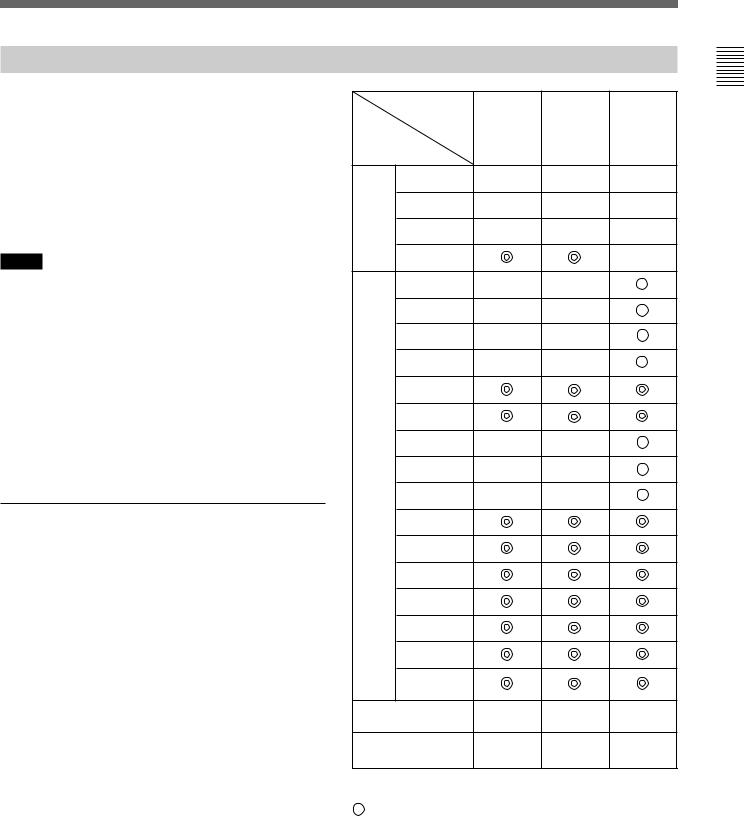
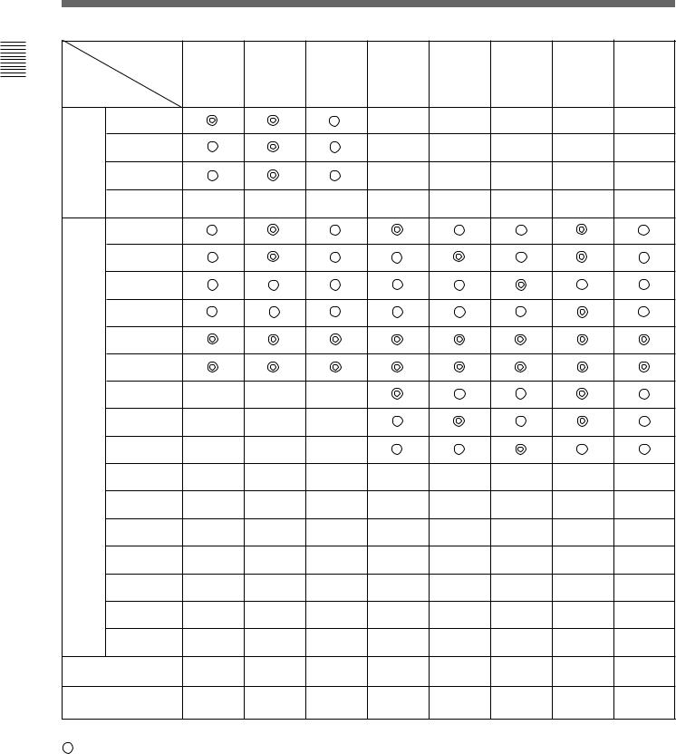
Connector Panel Configuration
The unit comes standard with connectors for one channel of Y/PB/PR or GBR. By adding the optional decoder adaptor or input expansion adaptors, the input/ output connector panel can be assembled in a wide variety of configurations. The signals that each of the adaptors’ connectors supports are given in the table below. The type of signal to be applied to each input/ output connector is set with the INPUT CONFIGURATION menu.
Notes
•One BKM-22X can be attached simultaneously with the BKM-20D or BKM-21D.
•The BKM-20D, BKM-21D and BKM-22X can not provide proper active-through outputs if a signal whose format is not selected in the INPUT CONFIGURATION menu is input. (If AUTO is selected, input a signal which has the same format with the signal monitored last.)
For information about the INPUT CONFIGURATION menu, see “ [C1] Setting the Input Configuration (SET UP 1)
— INPUT CONFIGURATION Menu” on page 35.
Priority of the decoder adaptors
When multiple decoder adaptors for NTSC or PAL format are installed, their priority is as in the following table.
Example: To monitor the composite NTSC signal when the BKM-24N and BKM-27T are installed, the input composite NTSC signal is always decoded by the BKM-24N.
Input signal and |
Decoder adaptor |
|
|
||
|
|
|
|
||
its format |
|
BKM-24N |
BKM-25P |
BKM-27T |
BKM-21D |
|
|
||||
|
|
|
|
|
|
Composite |
NTSC |
1 |
|
3 |
2 |
signal |
PAL |
|
1 |
3 |
2 |
|
|
|
|
|
|
YC |
NTSC |
1 |
|
2 |
|
signal |
PAL |
|
1 |
2 |
|
|
|
|
|
|
|
|
Adaptor |
BKM-41HD BKM-42HD |
BKM-48X1) |
||
|
name |
HD SDI |
HD SDI |
HD |
|
Signal |
Input |
Input |
Analog |
||
Adaptor |
Adaptor |
Expansion |
|||
format |
|||||
|
|
Adaptor |
|||
|
|
|
|
||
Serial |
Component |
|
|
|
|
digital |
525/625 |
|
|
|
|
input |
Composite |
|
|
|
|
|
NTSC |
|
|
|
|
|
Composite |
|
|
|
|
|
PAL |
|
|
|
|
|
HD SDI |
|
|
|
|
Analog Composite input NTSC
Composite PAL
Composite
PAL-M
Composite
SECAM
YPBPR 525/625
GBR 525/625
Y/C
NTSC
Y/C
PAL
Y/C
PAL-M
YPBPR/GBR 1080/48I
YPBPR/GBR 1080/50I
YPBPR/GBR 575/50P
YPBPR/GBR 480/60P
YPBPR/GBR 1035/60I
YPBPR/GBR 1080/60I
YPBPR/GBR |
|
|
|
|
720/60P |
|
|
|
|
Number of digital |
1 |
2 |
– |
|
inputs |
||||
|
|
|
||
Number of analog |
1 |
1 |
6 |
|
input |
||||
|
|
|
 Signal can be reproduced with this adaptor. Signal can be reproduced when using this adaptor together with an adaptor marked with
  .
.
1)Equipped with floating/non-floating ground mode selected for hum reduction.
(continued)
Overview 1 Chapter
7
Overview 1 Chapter
Overview
|
Adaptor |
BKM-20D |
BKM-21D |
BKM-22X |
BKM-24N |
BKM-25P |
BKM-26M |
BKM-27T |
BKM-28X |
|
|
SDI 4:2:2 |
SDI Multi |
SDI |
NTSC |
PAL |
PAL-M |
Tri- |
Analog |
||
|
name |
|||||||||
|
Decoder |
Decoder |
Input |
Decoder |
Decoder |
Decoder |
Standard |
Input |
||
Signal |
||||||||||
Adaptor |
Adaptor |
Expansion |
Adaptor |
Adaptor |
Adaptor |
Decoder |
Expansion |
|||
format |
||||||||||
|
|
Adaptor |
|
|
|
Adaptor |
Adaptor |
|||
|
|
|
|
|
|
|
||||
Serial |
Component |
|
|
|
|
|
|
|
|
|
digital |
525/625 |
|
|
|
|
|
|
|
|
|
input |
Composite |
|
|
|
|
|
|
|
|
|
|
NTSC |
|
|
|
|
|
|
|
|
|
|
Composite |
|
|
|
|
|
|
|
|
|
|
PAL |
|
|
|
|
|
|
|
|
|
|
HD SDI |
|
|
|
|
|
|
|
|
|
Analog Composite |
|
|
|
|
|
|
|
|
||
input |
NTSC |
|
|
|
|
|
|
|
|
|
|
Composite |
|
|
|
|
|
|
|
|
|
|
PAL |
|
|
|
|
|
|
|
|
|
|
Composite |
|
|
|
|
|
|
|
|
|
|
PAL-M |
|
|
|
|
|
|
|
|
|
|
Composite |
|
|
|
|
|
|
|
|
|
|
SECAM |
|
|
|
|
|
|
|
|
|
|
YPBPR |
|
|
|
|
|
|
|
|
|
|
525/625 |
|
|
|
|
|
|
|
|
|
|
GBR |
|
|
|
|
|
|
|
|
|
|
525/625 |
|
|
|
|
|
|
|
|
|
|
Y/C |
|
|
|
|
|
|
|
|
|
|
NTSC |
|
|
|
|
|
|
|
|
|
|
Y/C |
|
|
|
|
|
|
|
|
|
|
PAL |
|
|
|
|
|
|
|
|
|
|
Y/C |
|
|
|
|
|
|
|
|
|
|
PAL-M |
|
|
|
|
|
|
|
|
|
|
YPBPR/GBR |
|
|
|
|
|
|
|
|
|
|
1080/48I |
|
|
|
|
|
|
|
|
|
|
YPBPR/GBR |
|
|
|
|
|
|
|
|
|
|
1080/50I |
|
|
|
|
|
|
|
|
|
|
YPBPR/GBR |
|
|
|
|
|
|
|
|
|
|
575/50P |
|
|
|
|
|
|
|
|
|
|
YPBPR/GBR |
|
|
|
|
|
|
|
|
|
|
480/60P |
|
|
|
|
|
|
|
|
|
|
YPBPR/GBR |
|
|
|
|
|
|
|
|
|
|
1035/60I |
|
|
|
|
|
|
|
|
|
|
YPBPR/GBR |
|
|
|
|
|
|
|
|
|
|
1080/60I |
|
|
|
|
|
|
|
|
|
|
YPBPR/GBR |
|
|
|
|
|
|
|
|
|
|
720/60P |
|
|
|
|
|
|
|
|
|
Number of digital |
3 |
3 |
3 |
– |
– |
– |
– |
– |
||
inputs |
|
|||||||||
|
|
|
|
|
|
|
|
|
||
Number of analog |
3 |
3 |
3 |
6 |
6 |
6 |
6 |
6 |
||
input |
|
|||||||||
|
|
|
|
|
|
|
|
|
||
 Signal can be reproduced with this adaptor.
Signal can be reproduced when using this adaptor together with an adaptor marked with  .
.
8
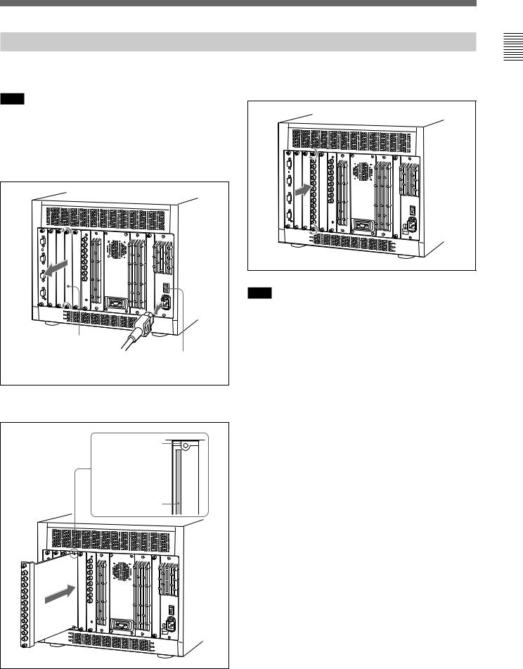
Installing a Decoder Adaptor
Each decoder adaptor can be installed in any input option slot.
Note
Turn off the main power of the monitor and disconnect the AC power cord before installing or removing adaptors.
1 Remove the cover of an input option slot on the rear panel of the monitor.
Cover of an input option slot
Make sure the MAIN POWER switch is turned OFF, and disconnect the AC power cord.
2 Insert the adaptor under the positioning mark on the top of the slot (on the left of the screw hole).
Positioning mark |
Insert the |
adaptor here. |
3 Push the adaptor in until it is firmly seated in the connector inside the monitor, then tighten the two screws to secure the adaptor.
Note
When installing a decoder adaptor in an input option slot on the rear of the monitor, or fitting a cover plate to an unused slot, always do such operation in order from the rightmost slot. If some adaptors are already installed, first of all remove them and then do the installing operation in order from the rightmost slot. When removing the adaptors, always loosen all adaptor screws and then remove the adaptors in order from the rightmost slot.
1 Chapter
Overview
9
Overview 1 Chapter
Location and Function of Parts
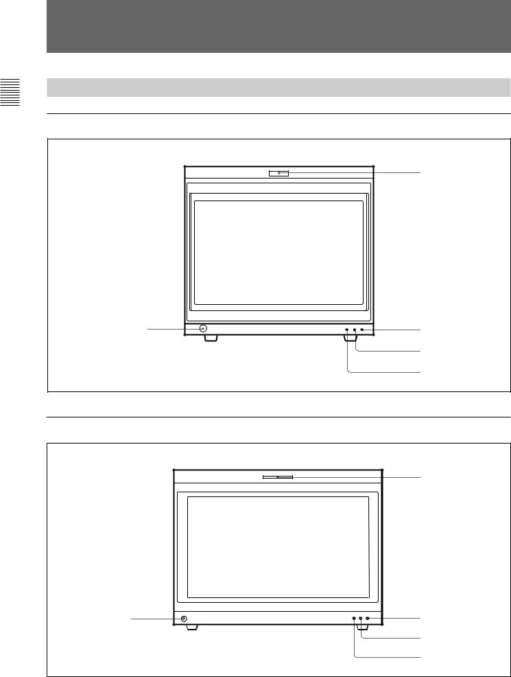
Front Panel
BVM-D20F1U/D20F1E/D20F1A
1 Tally lamp
5 OPTION connector |
2 POWER lamp |
|
3 STANDBY lamp |
|
4 OVER LOAD lamp |
BVM-D24E1WU/D24E1WE/D24E1WA/D32E1WU/D32E1WE/D32E1WA
1 Tally lamp
5 OPTION connector |
2 POWER lamp |
|
3 STANDBY lamp |
• The illustration above shows the BVM-D24E1WU/D24E1WE/D24E1WA. |
4 OVER LOAD lamp |
|
10

1 Tally lamp
With factory settings, the tally lamp lights when pins No. 8 and No. 9 of the REMOTE 2 connector on the rear panel are shorted. By changing the setting in the REMOTE menu, different pins on the remote connector can be used to control the tally lamp.
For information about the REMOTE menu, see “ [C2] Assigning the Remote Control Functions (SET UP 2)
— REMOTE Menu” on page 40.
2 POWER lamp
Lights when the monitor is put into operation mode from standby mode (see STANDBY lamp 3) by pressing the POWER switch of the BKM-10R/11R.
Note
When the STANDBY lamp 3 is blinking, the monitor cannot be put into operation mode (internal data initialization is taking place). Wait until the STANDBY lamp 3 is steadily lit.
3 STANDBY lamp
Lights when the monitor is in standby mode. The monitor will be in standby mode under the following conditions:
•The MAIN POWER switch (on the rear panel) is turned on (the STANDBY lamp will blink for a few moments after the switch is turned on, then will light).
•The monitor is changed from operation mode to standby mode by external control.
4 OVER LOAD lamp
Lights to warn of CRT overload.
When the OVER LOAD lamp is lit, use the unit with the contrast or brightness reduced.
5 OPTION connector
Used to connect the BKM-11R Monitor Control Unit or a auto setup probe (BKM-14L, etc).
Overview 1 Chapter
11

Overview 1 Chapter
Location and Function of Parts
Rear Panel
BVM-D20F1U/D20F1E/D20F1A
5Analog input/output connectors
6 Input option slots
7 REMOTE 1 connectors |
|
8 REMOTE 2 connector |
1 MAIN POWER switch |
|
|
9 ISR connector |
2 AC IN socket |
|
3 Fuse |
|
4 Deflection option slot |
!º CONTROL UNIT connector |
|
BVM-D24E1WU/D24E1WE/D24E1WA/D32E1WU/D32E1WE/D32E1WA
5 Analog input/output connectors
6 Input option slots
7 REMOTE 1 connectors
8 REMOTE 2 connector
9 ISR connector
!º CONTROL UNIT connector
• The illustration above shows the BVM-D24E1WU/D24E1WE/D24E1WA.
1 MAIN POWER switch
2 AC IN socket
3 Fuse
4Deflection option slot
(Digital uniformity adaptor installed as standard)
12
1 MAIN POWER switch
When turned on, the monitor enters operation mode. By setting in the SYSTEM CONFIGURATION menu, the monitor can also be set to enter standby mode when the MAIN POWER switch is turned on.
Note
When the monitor is turned on, “INITIALIZING” is displayed. While it is displayed, the monitor cannot accept commands from the BKM-10R/11R Monitor Control Unit or the equipment connected to the serial REMOTE 1 connector.
For information about the SYSTEM CONFIGURATION menu, see “ [C4] Setting the Channel Selection Method, Power-Up Conditions and Decoder (SET UP 4) — SYSTEM CONFIGURATION Menu” on page 44.
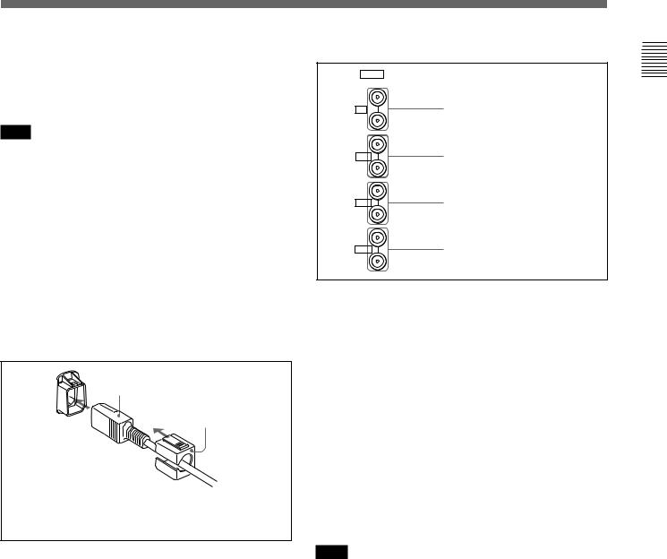
2 AC IN socket (3-pin)
Connects the monitor to an AC power source, via the supplied AC power cord.
AC power cord (supplied)
AC Plug holder (supplied)
Attach the AC Plug holder to the AC power cord, and connect it to the AC IN socket so that the cord does not come loose.
3 Fuse
Use a T4AH fuse.
4 Deflection option slot
For the BVM-D24E1WU/D24E1WE/D24E1WA/ D32E1WU/D32E1WE/D32E1WA, the digital uniformity adaptor has been installed at the factory. For the BVM-D20F1U/D20F1E/D20F1A, this slot is provided for future use.
5 Analog input/output connectors
ANALOG |
|
IN |
|
Y/G |
Y/G connectors (BNC) |
OUT |
|
IN |
|
PB/B |
PB/B connectors (BNC) |
OUT |
|
IN |
|
PR/R |
PR/R connectors (BNC) |
OUT |
|
IN |
|
SYNC |
SYNC connectors (BNC) |
OUT |
|
GBR signals, component signals (Y/PB/PR), or composite sync signals can be fed in the IN connectors. The type of signal applied to each connector is set with the INPUT CONFIGURATION menu. The OUT connectors are used for loop-through output of the input signal. When not using loop-through, connect a 75-ohm terminator (not supplied) to the OUT connectors.
For information about the INPUT CONFIGURATION menu, see “ [C1] Setting the Input Configuration (SET UP 1) — INPUT CONFIGURATION Menu” on page 35.
6 Input option slots
The monitor may be fitted with optional decoder adaptors.
Note
The BKM-41HD and BKM-42HD use two input option slots.
(continued)
Overview 1 Chapter
13
Overview 1 Chapter
Location and Function of Parts
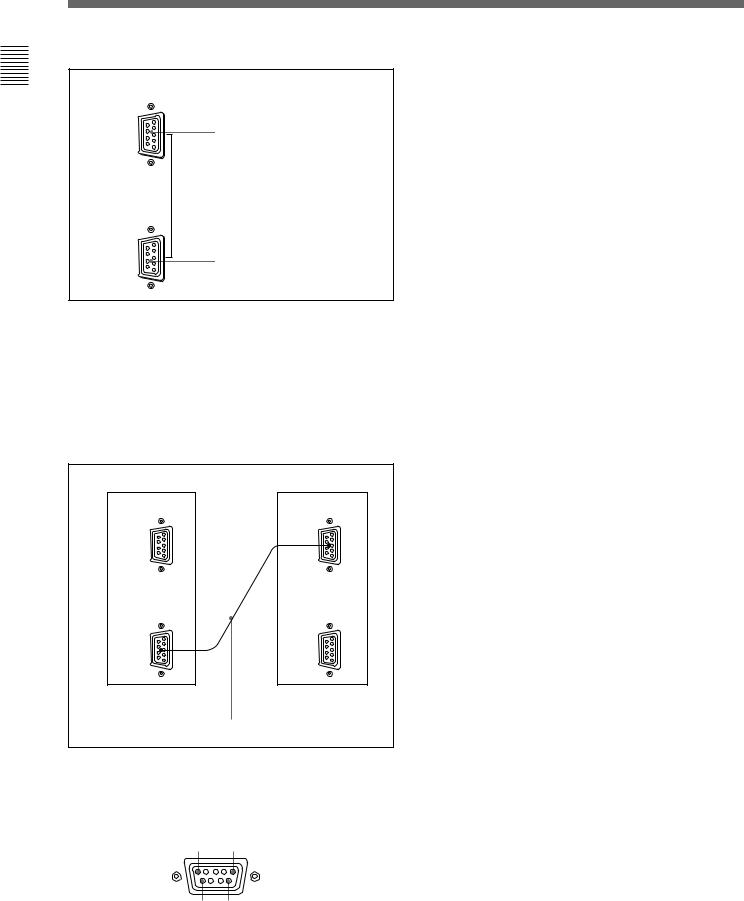
7 REMOTE 1 connectors (female, D-sub 9-pin)
REMOTE 1
IN |
REMOTE 1 IN connector |
|
OUT |
REMOTE 1 OUT connector |
|
Pin number |
Function |
|
|
1 |
Set input signal channel 1 (numeric keypad |
|
function) |
|
|
2 |
Set input signal channel 2 (numeric keypad |
|
function) |
3 |
Select sync signal (SYNC button function) |
|
|
4 |
Set the screen to monochrome, or set for |
|
automatic switching based on the input signal |
|
(MONO MODE button function) |
|
|
5 |
Safe area on/off (SAFE AREA button |
|
function) |
|
|
6, 7 |
Not connected |
|
|
8 |
Tally lamp on/off |
|
|
9 |
Ground |
|
|
These are RS-485 serial interface connectors, used for connecting two or more BVM-Dxx, BVM-xxE/F/G and HDM-xxE series monitors.
The IN and OUT connectors form a loop-through connection.
Connect two monitors using a cable with D-sub 9-pin plugs such as an RCC-5G (not supplied) as shown in the figure.
Monitor 1 |
Monitor 2 |
REMOTE 1 |
REMOTE 1 |
IN |
IN |
OUT |
OUT |
Cable with D-sub 9-pin plugs (not supplied)
8 REMOTE 2 connector (female, D-sub 9-pin)
Forms a parallel switch and controls the monitor externally. The pin assignment and factory setting function assigned to each pin are given below.
5 1
9 6
All pin function assignments can be changed with the REMOTE menu.
For information about the REMOTE menu, see “ [C2] Assigning the Remote Control Functions (SET UP 2) — REMOTE Menu” on page 40.
To switch each function between on and off or between enable and disable, change pin connections in the following way.
ON or enabled: Short each pin and pin 9 together. OFF or disabled: Leave each pin open.
9 ISR (Interactive Status Reporting) connector
(female, D-sub 9-pin)
Connect to the ISR system.
!º CONTROL UNIT connector (female, D-sub 9- pin)
Connects the BKM-10R Monitor Control Unit using a cable with D-sub 9-pin plugs such as an RCC-5G/10G/ 30G (not supplied) or the cable supplied with the BKM-32H/34H Monitor Control Unit Attachment Kit.
14
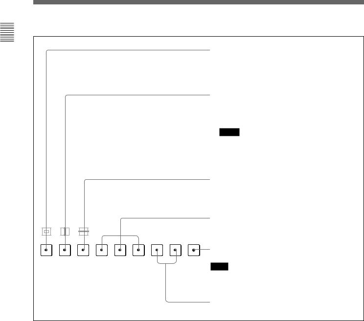
BKM-10R Monitor Control Unit (Optional)
This manual explains the location and function of parts and controls of the optional BKM-10R Monitor Control Unit. The explanation applies to the optional BKM-11R Monitor Control Unit.
Note
If you press the UP/DOWN buttons or ENTER button on the Monitor Control Unit quickly and repeatedly, it may cause the monitor to go out of control. In this case, turn the PHASE, CHROMA or another MANUAL adjustment knob to restore control.
1 Monitor memory card insertion slot
|
5 POWER switch |
|
6 DEGAUSS button |
|
7 DISPLAY UNIT |
|
connector (rear) |
2 SHIFT button |
|
3 Function buttons |
8 Numeric keypad |
4 Menu operation |
9 MANUAL adjustment |
buttons |
buttons and knobs |
1 Monitor memory card insertion slot
Insert the BKM-12Y Monitor Memory Card (optional).
For inserting/ejecting the monitor memory card, see page 20.
2 SHIFT button
Press to select one of the two functions designated to the function buttons 3.
Each time the SHIFT button is pressed, the LED turns on (SHIFT ON: lit in amber) and off (SHIFT OFF). SHIFT OFF: The functions indicated above the
function buttons can be used (the LED of the function button lits in green).
SHIFT ON: The functions indicated below the function buttons can be used (the LED of the function button lits in amber).
3 Function buttons
Change the operation conditions for the monitor. Each time the button is pressed, the LED turns on and turns off, and the operation conditions are changed. Each button has two functions. Select one of the two functions by pressing the SHIFT button 2. When the SHIFT button is set to ON, the LED lights in amber, and when the SHIFT button is set to OFF, the LED of each button lights in green.
For the functions of the function buttons in case of SHIFT OFF and SHIFT ON, see pages 17 and 18.
4 Menu operation buttons
UP |
MENU |
MENU button: Press to display the monitor |
|
menus. |
|||
DOWN |
ENTER |
UP/DOWN buttons: Press to select the |
|
items and setting values. |
|||
|
|
||
|
|
ENTER button: Press to confirm the items |
|
|
|
and values entered (Ent button on the |
|
|
|
numeric keypad 8 has the same function). |
|
|
|
|
For more information about menu operation, see “Basic Menu Operations” on page 22.
5 POWER switch
Press to turn on/off the monitor. By setting with the ADDRESS menu, it is possible to turn on/off the power of the specified monitors only, or of all monitors at the same time.
Note
When the monitor is turned on, “INITIALIZING” is displayed. While it is displayed, the monitor cannot accept commands from the BKM-10R/11R Monitor Control Unit or the equipment connected to the serial REMOTE 1 connector.
For information about the ADDRESS menu, see “Selecting the Monitor to Control — ADDRESS Menu” on page 60.
(continued)
Overview 1 Chapter
15
Overview 1 Chapter
Location and Function of Parts
6 DEGAUSS button
Press to degauss the CRT (every time the monitor is turned on, the CRT is degaussed automatically). To degauss again, wait for more than five minutes.
7 DISPLAY UNIT connector (rear)
Connect to the CONTROL UNIT connector of the monitor, using an optional RCC-5G/10G/30G cable or the cable supplied with the BKM-32H or BKM-34H Monitor Control Unit Attachment Kit.
The power is supplied from the monitor and the control signal is sent and received via this connector.
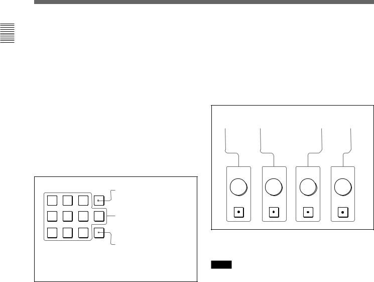
8 Numeric keypad
Use to designate the channel number for the input signal to be monitored, or to enter the setting values with the menus.
|
|
INPUT |
|
Del button: Deletes the values |
1 |
2 |
3 |
Del |
and characters entered. |
|
||||
4 |
5 |
6 |
0 |
Numeric buttons |
7 |
8 |
9 |
Ent |
|
Ent button: Confirms the values and characters entered (ENTER button of the menu operation buttons 4 has the same function).
Channel number entry method
When selecting a channel number from 1 to 9, press one-digit channel number on the numeric keypad. When selecting a channel number from 10 to 99, press 0 button, then press the two-digit channel number.
9 MANUAL adjustment buttons and knobs
Each press of one of these buttons turns the button’s green LED on or off. When the corresponding button is on (lit), it is possible to manually adjust the contrast, brightness, chroma and phase by turning the corresponding knobs. The PHASE knob is also used to enter the setting values with the menus. It is possible to set the preset value for each adjusting item with the CONTROL PRESET ADJ menu.
|
CHROMA |
BRIGHT |
CONTRAST |
PHASE button |
button |
button |
button and |
and knob |
and knob |
and knob |
knob |
PHASE |
CHROMA |
BRIGHT |
CONTRAST |
MANUAL |
MANUAL |
MANUAL |
MANUAL |
For information about the CONTROL PRESET ADJ menu, see “ [A] Preset Adjustment of the Picture Level Control Knobs — CONTROL PRESET ADJ menu” on page 28.
Notes
•The signal phase cannot be adjusted when using the composite SECAM, composite PAL D, component or SDI (component or composite serial digital interface) format.
•The phase and chroma cannot be adjusted when using GBR signals.
16
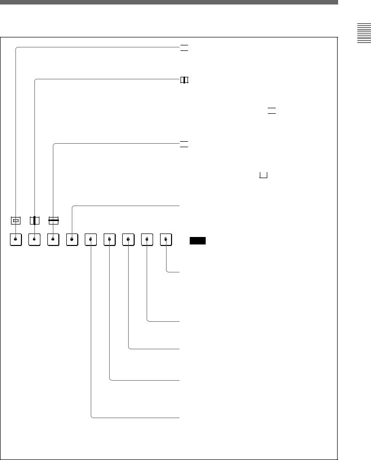
Function buttons in SHIFT OFF mode (LEDs of function buttons in green)
MONO APT COMB F1
16 : 9 SYNC |
BLUE |
R |
G |
B |
F3 |
|
ONLY |
||||||
|
|
|
|
|


 (Underscan) button: When this button is pushed in (ON), the picture is underscanned by 3%, and four ends of the raster is displayed on the screen.
(H delay) button: When this button is pushed in (ON), the picture moves horizontally, and a horizontal sync signal appears approximately 3/8 in the left edge of the screen.
•The brightness of the picture increases automatically, and it makes it easy to check the sync part.
•If it is pressed together with the 
 button, a pulse cross picture is displayed.

 (V delay) button: When this button is pushed in (ON), the picture moves vertically, and a vertical sync signal appears approximately in the center of the screen.
•The brightness of the picture increases automatically, and it makes it easy to check the sync part.
•If it is pressed together with  button, a pulse cross picture is displayed.
MONO button: When this button is pushed in (ON), a monochrome picture is displayed. When the buttons is off,
F2 ADDRESS the monitor switches automatically between color and monochrome mode, depending on the presence or absence
of color burst signal.
Note
F4 SAFE AREA
The MONO button does not function with the GBR signal input.
ADDRESS button: When this button is pushed in (ON), the ADDRESS menu appears on the screen. By using the ADDRESS menu, operation conditions for multiple monitors are set.
For more information about the ADDRESS menu, see “Selecting the Monitor to Control — ADDRESS Menu” on page 60.
F2 button: When this button is pushed in (ON), you can access directly the MANUAL menu of the level 2 of the COLOR TEMP ADJ menu, if the short-cut function is assigned to this button.
F1 button: When this button is pushed in (ON), the characters disappear from the monitor on the MANUAL menu of some menus.
COMB button: Turn the comb filter on and off.
This function is available when an optional decoder adaptor such as a BKM-24N is installed. (For NTSC, PAL and PAL-M only)
APT (aperture) button: When this button is pushed in (ON), the frequency response can be modified. The degree of modification is set with the menu.
For information about the aperture modification frequency for each signal format, see “Aperture modification frequency for each signal format” on page 19.
Overview 1 Chapter
17
Overview 1 Chapter
Location and Function of Parts
Function buttons in SHIFT ON mode (LEDs of function buttons in amber)
16:9 button: When this button is pushed in (ON), the aspect ratio changes to 16:9, and when set to OFF, the aspect ratio changes to 4:3.
The aspect ratio is fixed to 16:9 when the signal of some signal formats is input. For details, see “Available Signal
Formats” on page 65.
MONO APT COMB F1 |
F2 ADDRESS |
16 : 9 |
SYNC |
BLUE |
R |
G |
B |
F3 |
F4 |
SAFE |
|
ONLY |
AREA |
||||||||
|
|
|
|
|
|
|
SYNC button: When this button is pushed in (ON), the monitor synchronizes to the sync signal input to the SYNC connectors on the rear panel (EXT SYNC). When set to OFF, it synchronizes to the sync signal included in the signals being monitored (INT SYNC).
Notes
•When INT SYNC is selected, use a component or YC signals including a sync signal on the Y signal, and use GBR signal including a sync signal on the G signal.
•To monitor serial digital signals, always select INT SYNC.
BLUE ONLY button: When this button is pushed in (ON), red and green signals are cut, and only the blue signal is displayed as a monochrome picture. It makes it easy to adjust CHROMA and to check VTR noise.
R/G/B buttons: When these buttons are pushed in (ON), R(red), G(green), and B(blue) beams are cut respectively.
SAFE AREA button: When this button is pushed in (ON), a safe area is displayed on the screen.
Note
When EXT SYNC is selected, the safe area display possibly may not be shown in the correct position.
F3/F4 buttons: For future expansion.
18

Aperture modification frequency for each signal format
Signal format |
Serial digital input |
|
Analog input |
|
|
|
|
|
|
|
|
|
SDI |
HD SDI |
Composite |
Component |
GBR |
|
(Y/C) |
(YPBPR) |
|||
|
|
|
|
||
575/50I |
5 MHz |
|
5 MHz |
5 MHz* |
* |
|
|
|
|
|
|
480/60I |
5 MHz |
|
5 MHz |
5 MHz* |
* |
|
|
|
|
|
|
1080/48I |
|
25 MHz** |
|
25 MHz |
25 MHz |
|
|
|
|
|
|
1080/50I |
|
25 MHz** |
|
25 MHz |
25 MHz |
|
|
|
|
|
|
575/50P |
|
|
|
25 MHz |
25 MHz |
|
|
|
|
|
|
480/60P |
|
|
|
25 MHz |
25 MHz |
|
|
|
|
|
|
1035/60I |
|
25 MHz |
|
25 MHz |
25 MHz |
|
|
|
|
|
|
1080/60I |
|
25 MHz |
|
25 MHz |
25 MHz |
|
|
|
|
|
|
720/60P |
|
25 MHz** |
|
25 MHz |
25 MHz |
|
|
|
|
|
|
An empty frame in the table means that the signal cannot be input or the aperture modification can not operate for that signal even if it is input.
*The aperture modification frequency is 25 MHz when the signal is input via the analog input/output connectors (equipped as standard).
**The BKM-41HD and BKM-42HD with the serial number 2100001 to 2110000 cannot receive the HD SDI signal of the 1080/48I, 1080/50I or 720/60P format. To receive all of the above signal formats, use the BKM-41HD and BKM-42HD with a serial number from 2600001 to 2610001.
Overview 1 Chapter
19
 Loading...