

Page 1
Overview of equipment
100% Black+Silver
for light surfaces
Overview of equipment
GUARANTEE
Front side of the receiver
Rear side of the receiver
The remote control
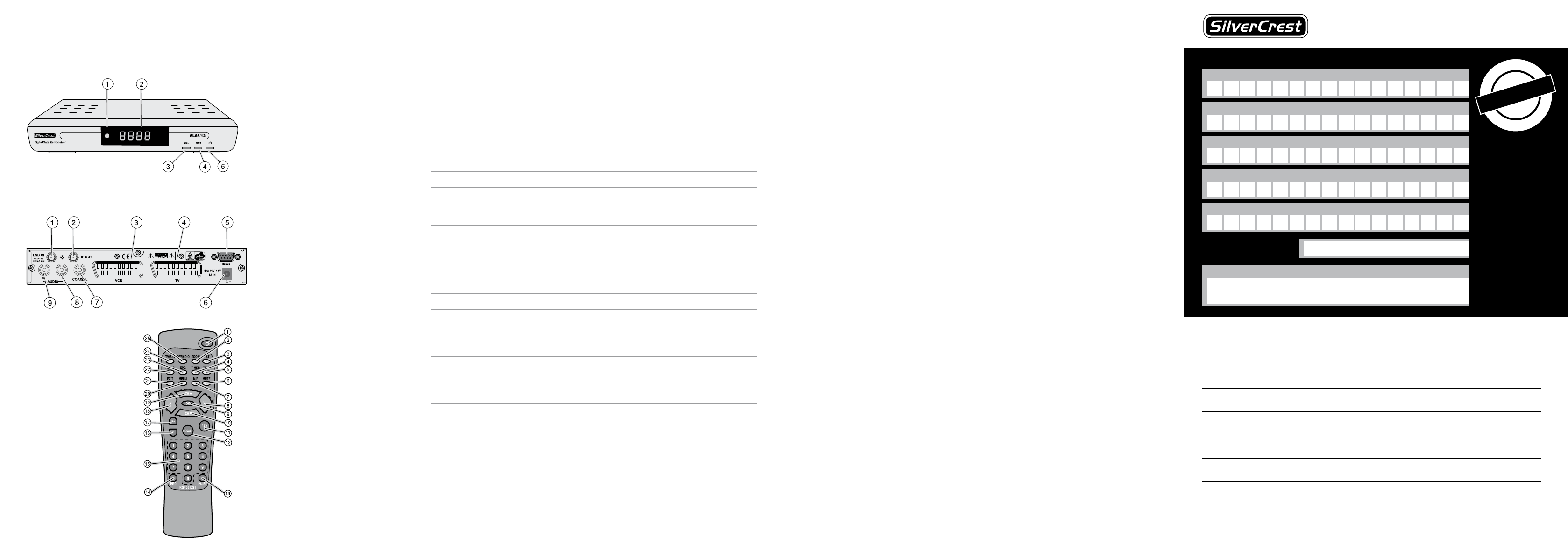
Front side of the receiver
1 – Infrared sensor for the signals of the remote control
2 LED display Shows the channel location in operating mode.
Shows time in standby mode.
3 CH- key Switches to the next lower channel location
Cursor moves down
4 CH+ key Switches to the next higher channel location
Cursor moves up
5 Standby key Switches on and switches to the standby mode
The default settings will be restored if you keep this key
pressed for more than 10 seconds. Caution! By doing this,
your personal settings will be deleted.
Rear side of the receiver
1 LNB IN LNB connection for the antenna cable
2 IF OUT LNB connection for a second satellite receiver
3 VCR (output) SCART connection for the video set
4 TV (output) SCART connection for the TV set
5 RS 232 Serial port
6 + DC 11V – 14V Connection 12V/power pack
7 COAXIAL Digital coaxial audio output
8 AUDIO L Stereo audio connection L(eft)
9 AUDIO R Stereo audio connection R(ight)
Sender please use block-writing in boxes with CAPITAL LETTERS
Surname
Firstname
Street
Postcode and city
Telefon no. with areacode
Model / Type:
Signature of buyer
PLEASE CUT THIS CARD AND ENCLOSE IT TO THE RETURNING GOOD
Faulty-Description:
t
h
n
s
o
•
m
6
3
•
•
Guarantee
•
•
f
r
o
m
Zintek Systems Ltd
Zintek House
Eurohaul Centre
Greenhills Road
Tallaght
Dublin 24
Service-Hotline:
00353 (0) 1400 8353
E-Mail:
info@zintek.tv
•
s
a
h
p
c
r
u
•
•
e
t
a
d
-
e
#
Page 2

COMAG Handels AG
Zillenhardtstr. 41
73037 Göppingen (Germany)
DIGITAL CAMPING
SATELLITE SYSTEM
Last Information Update · Tietojen tila · Informationsstatus · Tilstand af information
Opplysningenes gyldighet · Έκδοση των πληροφοριών · Stan informacji · Stanje informacija
Stand der Informationen: 01 / 2008 Ident.-No.: 012008 - 3
DIGITAL CAMPING SATELLITE SYSTEM
Operation and Safety Notes
DIGITAALINEN RETKI- V
SATELLIITTILAITTEISTO
Käyttö- ja turvallisuusohjeet
ΨΗΦΙΑΚΟ ΣΥΣΤΗΜΑ ΔΟΡΥΦΟΡΙΚΗΣ
ΛΗΨΗΣ ΓΙΑ ΤΟ ΚΑΜΠΙΝΓΚ
Υποδείξεις χειρισμού και ασφαλείας
DIGITALT CAMPINGSAT-ANLEGG
Betjenings- og sikkerhetshenvisninger
DIGITALT CAMPINGSATELLITANLÆG
Brugs- og sikkerhedsanvisninger
DIGITAL CAMPINGSAT-ANLÄGGNING
Bruksanvisning och säkerhetsanvisningar
DIGITALE CAMPING SAT-ANLAGE
Bedienungs- und Sicherheitshinweise
KEMPINGOWA CYFROWA
INSTALACJA SATELITARNA
Wskazówki dotyczące obsługi i bezpieczeństwa
DIGITALNI SATELITSKI
UREĐAJ ZA KAMPIRANJE
Upute za posluživanje i za Vašu sigurnost
Digital Camping
Satellite System
SL 65/12
Operating manual
Please open!Please open!
Page 3

The remote control
1 Standby Switches on and to the standby mode
2 ZOOM Enlarges TV image
3 LIST Invokes TV channel list
4 TIMER Invokes timer
5 TEXT Invokes Teletext
6 MUTE Turns off sound
7 M/P Multi-picture function, invokes thumbnail view
8 V+ Increases volume/cursor moves to the right
9 OK In normal mode: invokes current channel list In a
menu: confirms menu item
10 CH
11 FAV Invokes own favorite list
12 RECALL Switches to previously selected channel
13 PAUSE Stills the frame
14 INFO Displays reception data of the current channel
15 0–9 Selects channel directly, numerical input
16 P– In normal mode: changes channel group
17 P+ In normal mode: changes channel group
18 V– Decreases volume/cursor moves to the left
19 CH
20 MENU Invokes main menu
21 EXIT Exits menu or menu item
22 AUDIO Changes audio mode
23 EPG Invokes Electronic Programme Guide (if offered by
24 TV/SAT Switches between terrestrial and satellite antenna
25 TV/RADIO Switches between TV and radio mode
Switches to the next lower channel location/
cursor moves down
(satellite-finder function)
In TV channel list: Ten-key block commutation
In TV channel list: Ten-key block commutation
Switches to the next higher channel location/
cursor moves up
the broadcasting station)
Page 4
Digital Camping Satellite System
SL 65/12
Operating manual
Version 1.4 IE, as of 01/07/2008
Modifications and errors reserved.
We do not assume any liability for printing errors.
Dear customer,
Having in mind an environmentally friendly behaviour we
ask you to switch off your receiver after usage.
With this, you will contribute to the protection of the
environment and save money.
2
Page 5

Preface
This operating manual will help you in the
• appropriate
• safe
usage of the digital mini satellite system SL 65/12,
hereafter called the “satellite system” in short.
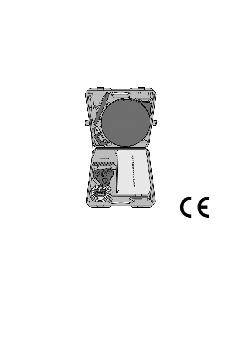
The satellite system is packed in a sturdy case and
consists of:
• a digital satellite receiver SL 65/12 (receiver unit),
hereafter called the receiver in short and
• the antenna unit with installation material.
We assume that users of the satellite system have overall
knowledge regarding handling audio and video
equipment.
Every person who
• installs,
• connects,
• operates,
• cleans
• disposes of
this satellite system must be familiar with the entire
content of this operating manual. Always keep this
operating manual in the proximity of the satellite system.
3
Page 6

Style features
Specific style features have been given in different
sections of the operating manual. Thus, you can easily
differentiate whether it concerns
normal text,
• enumerations or
actions.
.
4
Page 7
Contents
Contents
Preface............................................................................3
Style features .................................................................4
Contents .........................................................................5
Safety instructions.........................................................8
Basic safety instructions .......................................8
Appropriate use ...........................................................13
Scope of supply ...........................................................15
Description ...................................................................17
Quick guide ..................................................................22
Antenna installation.....................................................23
Installation of the LNB and dish antenna ..................23
Suitable location/Rough direction of the antenna ....25
Installation options......................................................29
Receiver connection....................................................41
LNB cable installation .................................................42
Connection with Scart cable.......................................47
Connection with the Cinch cable................................49
Connection of an audio-digital receiver.....................49
Direction of the antenna..............................................51
Getting started .............................................................53
Remote control ............................................................53
The receiver..................................................................55
Fine adjustment of the antenna..................................57
Operation......................................................................60
5
Page 8

Contents
Screen-inlays while switching channels....................60
User interface on the TV screen .................................62
Menu structure.............................................................62
Menu structure.............................................................63
Menu navigation ..........................................................64
Channel (symbol: TV)..................................................65
Installation (symbol: satellite antenna)......................71
System Setup (symbol: receiver) ...............................75
Tools (symbol: tool case)............................................81
Software update via satellite.......................................82
Keys with special functions........................................83
Switch between TV and SAT.......................................83
Switch between TV and radio .....................................83
ZOOM............................................................................83
LIST...............................................................................84
AUDIO ...........................................................................84
EPG ...............................................................................84
TEXT..............................................................................85
M/P ................................................................................85
MUTE.............................................................................86
FAV................................................................................86
RECALL ........................................................................86
INFO - acoustic signal for directing the satellite
antenna .........................................................................87
0 - Sleep timer ..............................................................87
PAUSE ..........................................................................87
Dismantling the satellite system ................................88
Cleaning........................................................................89
Maintenance .................................................................89
Tips & tricks/trouble shooting ....................................90
Disposal........................................................................94
Specifications ..............................................................95
6
Page 9

Contents
Manufacturer ................................................................97
Guarantee .....................................................................98
Declaration of conformity ...........................................99
Index ...........................................................................100
Glossary .....................................................................103
7
Page 10
Safety instructions
Safety instructions
Please read the safety instructions carefully before
operating the satellite system.
Please follow all warnings and instructions on the
equipment and in the operating manual.
Basic safety instructions
Electrical connection
• Do not expose the receiver to rain or any kind of
humidity to avoid risk of fire and electric shock.
• Never open the casing. Otherwise, there is a risk of
electric shock.
• Connect the receiver only to the power source
installed by an expert. It is either:
- for an external power pack:
a 100–240 V~, 50-60 Hz mains socket as per
specifications or
- for a 12 V cable:
a 11 V – max. 14 V DC supply as per specifications.
• Ensure that the total power consumption by the
antenna connection of the receiver does not exceed
“LNB IN” 300 mA.
• Pull the external power pack or the 12 V cable out of
the mains socket if you will not use the device for a
longer period of time. Only pull at the external power
pack or at the head piece of the 12 V cable, not at the
cable itself.
• In case of a storm, pull the external power pack or the
12 V cable of the receiver out of the mains socket.
8
Page 11

Safety instructions
• In case of a storm, unscrew the LNB cable from the
receiver.
• Only use the external power pack or the 12 volt cable
for the cigarette lighter included in the scope of supply
for operation of the receiver.
• Always replace the fuse of the 12 volt cable for the
cigarette lighter with the type T2AL/250 V
(characteristics: 2 amperes/250 volts/time-delay).
• If foreign bodies or fluids enter the receiver,
immediately pull out the external power pack or the
12V cable out of the socket. Ask a qualified person to
check the equipment before operating it once again.
Otherwise, there is a risk of electric shock.
• Do not bend or crimp any cable.
• If a cable used for mains supply is damaged, the
receiver must be repaired by an expert before reusing
it. Otherwise, there is a risk of electric shock.
• Never allow children to operate the receiver or to play
with the antenna unit unless supervised.
• Always ask qualified personnel to carry out
maintenance jobs. Otherwise, you are putting yourself
and others at risk.
• Disconnect the receiver from the power source in case
of operational disruptions.
• Ensure that the power source is easily accessible.
• Spare parts must be ordered directly from the
manufacturer
• Modifications of the device lead to an extinction of the
manufacturer’s liability.
• Remove the protection films.
9
Page 12

Safety instructions
Caution!
Note on disconnection from the mains supply. The
standby button on this device does not completely
disconnect the device from the mains supply. In
addition, the device carries a current in standby mode.
To completely disconnect the device from the mains
supply, the mains adapter must be pulled out of the
mains socket.
Correct position
• Place the receiver on a stable and even base.
• Use the receiver only with adequate climatic
conditions.
• Avoid proximity to:
- heat sources, like e. g. heaters,
- naked flames, like e. g. candles,
- devices with strong magnetic fields, like e.g.
loudspeakers.
- Never place receptacles filled with liquid (vases) on
the receiver.
• Avoid direct sunlight and places with an extremely high
amount of dust.
• Never cover ventilation slits. Provide for sufficient
ventilation by maintaining a safety distance of 5 cm to
other objects.
• Do not place any heavy objects on the receiver.
• Humidity may settle in the receiver if it is brought into
hot surroundings from a cold one. In this case, wait for
about an hour before operating the equipment.
10
Page 13

Safety instructions
• Arrange all cables in such a manner that no-one steps
or trips over them.
• The antenna unit is not suitable for operating in case
of high wind pressures. Do not expose it to strong
wind.
Correct battery handling
• Batteries may contain toxic agents. Ensure that
batteries are not within the reach of children. Children
may eat and swallow batteries.
• Batteries that are getting discharged may damage the
remote control. If the receiver is not in use for a longer
period of time, remove the batteries from the remote
control.
• Batteries may contain toxic agents. Therefore, dispose
of the batteries immediately in an ecologically
accepted manner according to the prevailing statutory
regulations. Never throw the batteries into normal
household waste.
• Never expose the batteries to open fire or strong heat,
as otherwise there is a danger of explosion.
• Replace the batteries always by batteries of the same
type.
Explanation of safety instructions
The following categories of safety instructions are
included in the operating manual:
Danger!
Instructions with the word DANGER give a warning
against possible personal injuries.
11
Page 14

Safety instructions
Caution!
Instructions with the word CAUTION give a warning
against possible material or environmental damages.
These instructions contain special information for
the commercial use of the satellite system.
12
Page 15

Safety instructions
Appropriate use
The satellite system receives unencrypted digital satellite
channels for private use. It is exclusively meant for this
purpose and must only be used for the same. This also
includes paying attention to all information contained in
these operating instructions, especially the safety
instructions.
Due to its user-friendly installation and disassembly, the
satellite system is ideal for mobile use (camping or
caravans). As there are diverse installation options, the
system can be used in many places:
• on vehicle roofs
• at balustrades
• at masts
• at tables
• at walls
• etc.
Please follow the safety instructions listed below for all
kinds of installation:
Do not expose the satellite system to high loads due to
wind pressures (storms, squalls, installation in great
heights, etc.).
Wind speed
(km/h)
40 50 60 70 80 90 100 110
Load of the
antenna due
to wind
pressure (N)
13
12,64 19,70 28,42 38,71 50,57 63,99 78,99 206
Page 16
Safety instructions
Caution!
Do not expose the satellite system to high loads due to
wind pressures, e.g.
- installation in great heights (balcony railings)
- storm (wind speed > 75 km/h)
In case of non-observance, there is a risk of damage to
property and personal injury.
Caution!
The maximum bending moment of the satellite system
is 26.30 Nm. Please make sure during installation that
the fixation is able to withstand this pressure.
Amongst others, information on wind speed is available
on the Internet.
Do not install the satellite system at places with difficult
accessibility. Mount the satellite system only at places at
which it will be easily accessible for you without any
danger. Make sure that in case of need you will always
be able to remove the system.
An installation on vehicle roofs may only be carried out
while the vehicle is stationary with the parking brake
applied.
Any other usage is considered to be improper and may
lead to material damages and even personal injuries.
Do not leave the satellite system unattended.
COMAG Handels AG does not bear any liability for
damages caused due to improper use.
14
Page 17
Scope of supply
Scope of supply
Check the scope of supply after purchase.
The receiver, the remote control, the 2 batteries, the
external power pack and the 12V cable for the
cigarette lighter are included in a cardboard box, the
accessories in the integrated box. We recommend
packing these pieces again in the box when
dismounting the system.
15
Page 18

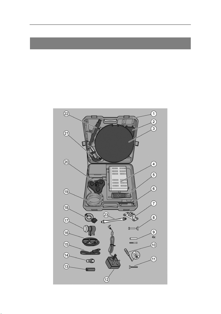
Scope of supply
No. Pieces Description
1 1 Case
2 1 Satellite locator compass
3 1 Dish antenna
4 1 Digital satellite receiver SL 65/12
5 1 Remote control
6 1 Extension rod
7 1 Wall bracket
8 2 Coach bolt with wing nut for wall bracket
9 1 Clamping set for wall bracket
10 1 Crosstip screwdriver
11 1 Wing nut for supporting-arm locking device
12 1 External power pack
13 2 Batteries
14 4 F connector
15 1 12V cable for cigarette lighter
16 1 Scart cable
17 1 Single universal LNB
18 1 LNB bracket
19 1 10m coaxial cable (not mass-produced)
20 1 Suction foot
21 1 Screw clamp
22 1 Supporting arm
23 1 Window feed-through
16
Page 19

Description
Description
You can receive unencrypted (free-to-air) digital satellite
channels with the satellite system without depending on a
fix mounted satellite antenna. The mobile antenna allows
you to receive signals at different places, like e.g. on a
camping site. The antenna can be installed in a plastic
case be mounted, e.g. on a car roof, on a table plate or a
mast using the mounting components.
Naturally, you can also connect the receiver to a fix
installed satellite antenna.
It is not necessary to programme the receiver yet. The
most important broadcasting stations and satellites have
already been pre-programmed.
The following satellites have been pre-programmed
by the company:
• ASTRA1 19,2°E
• Hotbird 13,0°E
• Türksat 42°E
• ASTRA2 28,2°E
• Sirius2 5,0°E
• Amos/Atlantic 4-5°W
• HispaSat 30°W
• Eutel W2 16°E
• HellasSat 39°E
The satellite antenna has to be directed towards the
desired satellite.
Please note that the reception of the preset
satellites depends on the location. The satellite
system has been designed for mobile use.
17
Page 20

Description
Therefore not at each location all preset satellites
can be received due to the size of the antenna.
The receiver will scan for further new broadcasting
stations as soon as you initiate the automatic scan of
broadcasting stations for this satellite. Satellites not
preset may be added.
All receiver settings can be done easily using the user
interface (menu) on the TV screen.
The multilingual user interface supports the following
languages:
• German
• Italian
• Spanish
• Greek
• English
• Polish
• Czech
• Slovakian
• Hungarian
• Danish
• French
• Swedish
• Croatian
• Dutch
• Norwegian
• Slovenian
• Turkish
• Portuguese
18
Page 21

Description
Other features of the equipment:
• Software update via satellite Astra1 19° East or via
RS232 connection on the rear side of the device.
• Short switching time, fast boot process when switching
on the receiver
• Saves the channel last watched (Last Station Memory)
• LNB control logic (sound 0/22 kHz), max. current
delivery for LNB 300 mA
• Symbol rate 1-35 MS/s and 950-2150 MHz input
frequency
• Manual PID entry possible
• 3 keys at the frontage
• 4-digit LED display
• Plug & play
• External power pack 100–240 V~, 50/60 Hz, output:
12V; 1.0A
• 4,500 channel-storage locations
• Parental lock (preset password: 0000)
• 1 favorite list and 8 channel groups
• Automatic scanning of broadcasting stations
• List editor for broadcasting stations
• Analogue sound output through Cinch connector
(stereo), volume adjustment possible via remote
control
• AC3 coaxial output (digital-audio, SPDIF)
• 2 Euro-SCART connections for TV and video set
• Video output signal CVBS (via SCART)
19
Page 22

Description
• Loop-through-function in standby mode for the
connection of an analogue receiver
• Super fast videotext with a memory of 800 pages
• Digital radio reception, background image for radio
(background display)
• Additional channel information is displayed when the
channel is changed.
• DiSEqC 1.0, 1.2, Go-to X is supported if an
appropriate antenna unit is connected
• SWAP function (via Recall key)
• Screen aspect ratios can be set to 4:3, 16:9, and
automatically (letterbox)
• Multi-functional timer, 8x and linked with EPG, sleep
timer
• Electronic Programme Guide EPG (up to 14 days in
advance, channel-dependent)
• SCPC/MCPC reception standard C/Ku-band satellites
• Automatic selection of the TV standard with video
converter
• Zoom function
• Multi-picture function
20
Page 23

Description
• Digital satellite finder for optical and acoustic
adjustment of the paraboloidal-type reflector
A suitable channel editor is additionally available
through our hotline. Then you will be able to edit
the channel lists of the receiver using your
computer. Please read the information on our
website for this purpose.
Please note that under the Web address:
www.mysilvercrest.de
• current software versions (if required)
• and channel-list editing software for the PC
can be downloaded.
Should you have any questions please contact our
service hotline.
21
Page 24

Quick guide
Quick guide
You must install, connect and adjust your satellite system
in the following sequence to be able to use it.
Install the antenna.
Install the LNB cable.
Connect the LNB cable to the antenna and the
receiver.
Direct the antenna roughly.
Connect the receiver to the equipment.
Insert the batteries in the remote control.
Connect the receiver and the equipment to the power
source and switch them on.
Set the channels using the remote control.
Direct the antenna finely if the reception quality is not
satisfactory.
If you would like to do individual settings for the
receiver, invoke the user interface on the TV screen.
Make the desired settings in the menus.
22
Page 25
Antenna installation
Antenna installation
The antenna consists of a few individual components and
is simple to install.
Remove the system components from the case.
Turn the antenna slightly to the left. This way it is
easier to take them out.
Remove the packing material.
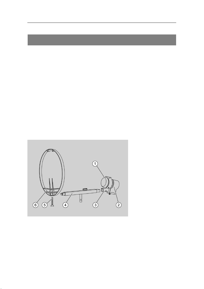
Installation of the LNB and dish antenna
Completely unscrew the 3 screws of the LNB bracket
(3) using the crosstip screwdriver.
Place the LNB (2) between the two halves of the LNB
bracket as shown in the picture (1).
Now, tighten the screws of the LNB bracket slightly
again. Tighten the screws uniformly (symmetrically).
Insert the LNB bracket in the supporting arm (4) at the
marking "LNB".
23
Page 26

Antenna installation
Tighten the screws of the LNB bracket uniformly
(symmetrically).
Place the supporting arm on the antenna dish (6).
Use the wing nut (5) included in the scope of supply
for fixing the supporting arm.
When installing in the case, please do not use the
wing nut. For all other installation types, please
use the wing nut for fixing the supporting arm at
the reflector. Tighten the screws of the LNB
bracket only in such a way that the LNB is fixed.
If you tighten them too much, the LNB bracket
could break.
24
Page 27
Antenna installation
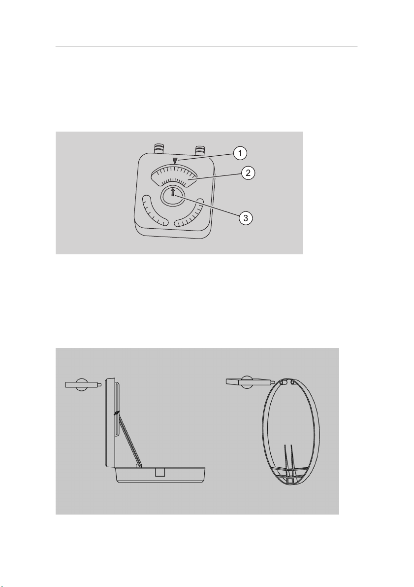
Suitable location/Rough direction of the antenna
You must find a suitable location before installing the
antenna. The satellite locator compass will help you for
this purpose.
Different cities are marked on the outer side of the
locating disc (2) and different satellites are marked on the
inner side.
Insert the nipples of the satellite locator compass in
the corresponding holes of the dish antenna or in the
case cover.
25
Page 28

Antenna installation
Turn the locating disc on the satellite locator compass
in such a manner that your location points to the “City“
marking (1).
26
Page 29

Antenna installation
There are only few cities and the most popular
satellites marked on the locating disk. Select the
city that is closest to your location and the
desired satellite.
Now turn the case or the dish antenna to the right or
left so that the arrow head of the compass needle (3)
points to the area of the satellite you would like to
receive.
Now the antenna points towards the direction from which
you receive the desired satellite signals.
No objects or buildings should obstruct the
reception in this direction. You must have a free
view in this direction when you stand behind the
antenna.
The antenna must not be installed behind a
balcony balustrade or a house balustrade. This
must be considered with all installation types.
You can use the adjustment of any existing
satellite antennas nearby as a reference during
the rough adjustment.
27
Page 30
Antenna installation
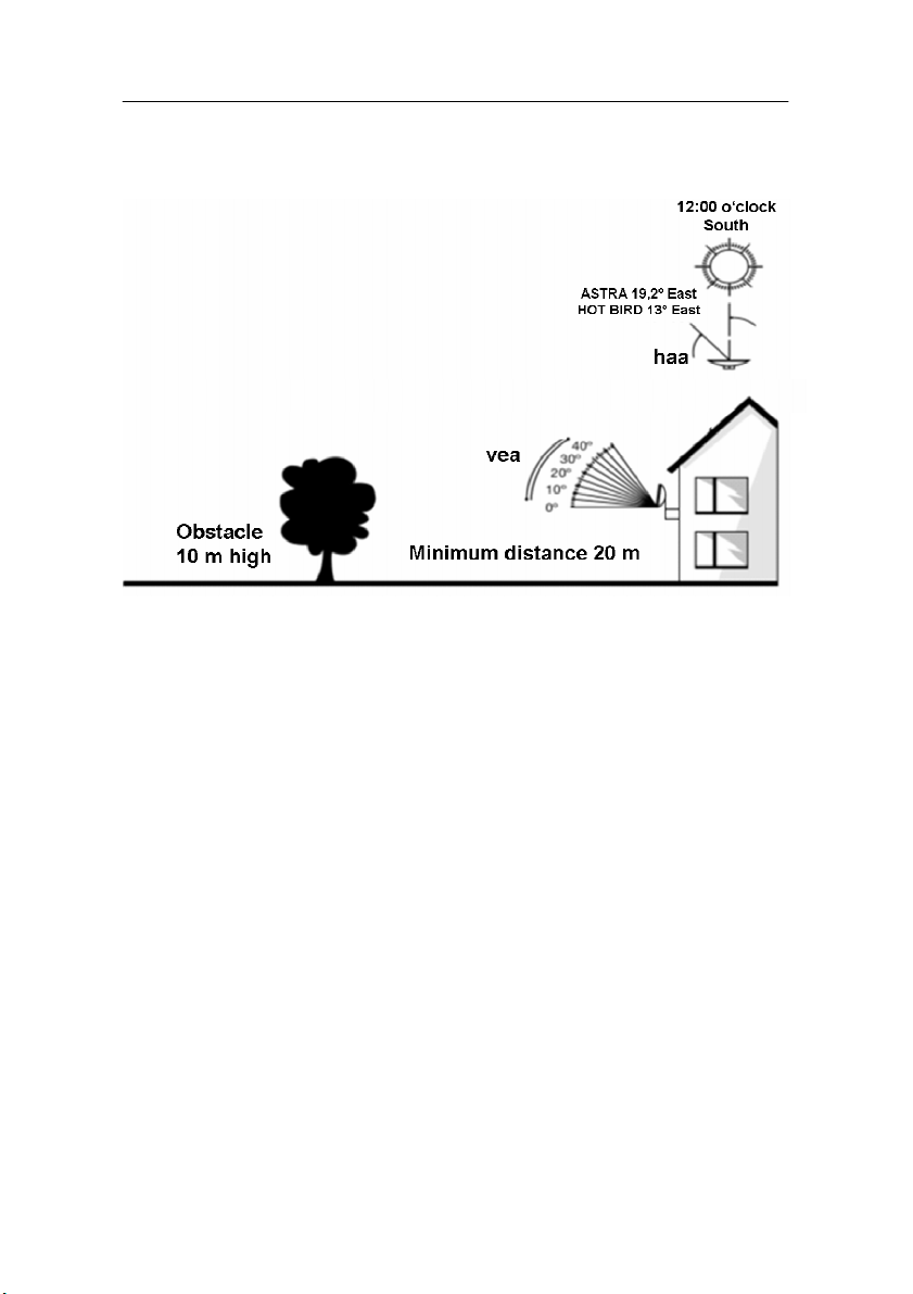
Example for an installation on a wall:
vea = vertical elevation angle
haa = horizontal azimuth angle
The satellite locator compass is only designed for a rough
adjustment. The fine adjustment is explained on page 57.
The receiver is equipped with an integrated
satellite finder which will support you when
installing the satellite system.
28
Page 31

Antenna installation
Installation options
The antenna can be set up in different ways using the
installation material provided. For clarification, the
installation options are illustrated in the pictures below..
To make the picture less complex the antenna cable is
not illustrated here. For a complete installation of the
satellite system, the LNB must be fixed.
Please observe all prohibitions or information of
the local administration (if any).
When selecting an installation place you should
make sure in any case that there are no obstacles
between the antenna and the satellite. No tree,
house, pane or other obstacles must block
visibility.
As a general rule:
An obstacle may only be half the size as its
distance to the antenna.
This must be considered with all installation
types.
With all installation options there may be slight
damages at the surface of the installation place.
You can protect the sensitive surface from
scratches and pressure marks by placing a piece
of felt, cardboard or similar.
29
Page 32

Antenna installation
Installation in the case
Open the cover of the case and tighten the wing nut
(3) to secure it against closing.
Insert the dish antenna in its bracket in the case. For
this purpose, turn the dish antenna about 3 cm to the
left starting from its original position and insert it in the
case by applying an adequate pressure. Now, turn the
dish antenna back to its original position.
Insert the supporting arm (1) with the LNB in the
opening of the dish antenna (2).
Put sufficient weight on the case, e.g. books, to
avoid a tipping over by an unintentional external
influence (e.g. wind).
For this installation, please do not use the wing
nuts of the supporting arm.
30
Page 33

Antenna installation
Installation on a mast
Put the screw clamp (4) on a mast, a rod or similar so
that notches rest against the screw end on the mast.
Caution!
You can protect the sensitive surface from scratches
and pressure marks by placing a piece of felt,
cardboard or similar. Please use the protective cap for
the screw clamp.
Tighten the screw clamp.
Insert the extension rod (3) in the mounting bore of the
screw clamp.
Tighten the wing nut on the screw clamp to fix the
extension rod.
31
Page 34

Antenna installation
Insert the supporting arm (1) with a mounted dish
antenna and LNB in the mounting bore of the
extension rod.
The pin of the supporting arm that is inserted in the
mounting bore has a bevelled side. The wing nut of the
extension rod (2) must touch this side of the pin of the
supporting arm. Tighten the wing nut of the extension
rod (2).
The maximum diameter of the mast must not
exceed 60mm.
32
Page 35

Antenna installation
Installation on a balustrade
Put the screw clamp (2) on the balustrade so that
notches rest against the screw end on the balustrade.
Caution!
You can protect the sensitive surface from scratches
and pressure marks by placing a piece of felt,
cardboard or similar. Please use the protective cap for
the screw clamp.
Tighten the screw clamp.
Insert the supporting arm (1) with a mounted antenna
dish and LNB in the mounting bore of the screw clamp.
The pin of the supporting arm that is inserted in the
mounting bore has a bevelled side. The wing nut of the
33
Page 36

Antenna installation
screw clamp (3) must touch this side of the pin of the
supporting arm. Tighten the wing nut on the screw
clamp (3) to fix the supporting arm.
The maximum diameter of the balustrade must
not exceed 60mm.
34
Page 37

Antenna installation
Installation on a table
Tighten the screw clamp (2) on the table plate.
Caution!
You can protect the sensitive surface from scratches
and pressure marks by placing a piece of felt,
cardboard or similar. Please use the protective cap for
the screw clamp.
Insert the supporting arm (1) with a mounted antenna
dish and LNB in the mounting bore of the screw clamp.
The pin of the supporting arm that is inserted in the
mounting bore has a bevelled side. The wing nut of the
screw clamp (3) must touch this side of the pin of the
supporting arm. Tighten the wing nut on the screw
clamp (3) to fix the supporting arm.
35
Page 38

Antenna installation
The maximum diameter of the table plate must
not exceed 60mm.
Installation on a suction foot
Place the suction foot (4) on a smooth and even
surface, e.g. your car roof..
Caution!
Clean the surface first to prevent scratches.
Tighten three screw plugs (3) in clockwise direction.
This generates vacuum at the rubber seats, which
fixes the suction foot on the surface.
Insert the supporting arm (1) with a mounted dish
antenna and LNB in the mounting bore of the suction
foot.
Tighten the wing nut on the suction foot (2).
To facilitate installation or to increase the suction
pressure, the 3 suction feet should first be wetted
36
Page 39

Antenna installation
slightly. If you have mounted the antenna on the
car roof, you must dismantle it before driving the
car again.
This installation type is not adequate for
permanent installation. Please check the
adhesion of the suction foot regularly.
Caution!
After having fixed the suction foot, remove the fixing
buttons of the screwed plug and store them. This way
you bar unauthorised third parties from manipulating
the fixture.
37
Page 40

Antenna installation
Installation on a wall
Place the wall bracket (4) at the position it should be
installed.
Mark the position of the four boreholes. Boring
distances:
Drill the four boreholes. The size of the bore holes
must correspond to the dowels included in the scope
of supply.
38
Page 41

Antenna installation
For an installation at a wood truss, the pre-drilling
must not exceed a drill diameter (Ø) of 4mm and
a depth of max. 20mm. Please do not use dowels
here.
Countersink the four steel dowels into the boreholes.
Attach the wall bracket and tighten it with the four
screws.
Insert the extension rod (3) in the wall bracket.
Insert both coach bolts to the right and left through the
wall bracket, or untighten the screws if they have been
pre-installed.
Fasten the nuts on the coach bolts and tighten them
alternatively until the extension rod is fixed in the wall
bracket.
Insert the supporting arm (1) with a mounted dish
antenna and LNB in the mounting bore of the
extension rod.
The pin of the supporting arm that is inserted in the
mounting bore has a bevelled side. The wing nut of the
extension rod (2) must touch this side of the pin of the
supporting arm. Tighten the wing nut of the extension
rod (2).
Wrench size: 13; depth of the bore holes (brick or
concrete foundation): 55mm; drill: Ø 10mm
Caution!
Consider that the installation on a wall can be
compared with a fix installation. Therefore, it can alter
the surface of the wall.
39
Page 42

Antenna installation
Before boring make sure that no conductions, tubes,
etc. will be damaged.
40
Page 43

Receiver connection
Receiver connection
The receiver is connected with your satellite antenna by
means of a coaxial cable. If necessary, you will have to
prepare a coaxial cable before connecting the receiver.
Caution!
Connect the receiver to the mains supply only after you
have connected it to all equipment and the antenna
properly. Otherwise, the receiver can suffer damages.
The wire netting and the inner core of the coaxial cable
carry current during operation.
Usage for camping and/or caravans:
The receiver can also be operated with 12V (i.e.
11-14V, e.g. solar panel, vehicles). Please use a
12V cable for this purpose.
Caution! In case of vehicles with an on-board
power-supply voltage of 24V (e.g. freight
vehicles), please use a 24V/12V DC-DC
converter. Otherwise, the receiver could suffer
damages. You will lose your guarantee in case of
non-observance.
41
Page 44

Receiver connection
LNB cable installation
(cf. following installation diagram)
For the installation of the F connector on the coaxial
cable you will need a knife (ideally a wire stripper) and
side cutting pliers.
When stripping the isolation, neither the inner
core or the foil nor the wire netting must be
damaged.
Cut 8 mm of the coaxial cable at each end up to the
inner core.
Carefully cut 10 mm of the outer insulation so that the
wire netting is exposed.
Turn the wire netting backwards and wind it over the
outer insulation in such a manner that it does not touch
the inner core.
Remove the inner insulation together with the foil
placed over it up to 2mm before reaching the wire
netting.
Caution!
The wire netting and the foil must not touch the inner
core. The foil must enclose the inner insulation and
must not be damaged.
Rotate the F connector onto the turned-back wire
netting until the connector touches the inner insulation.
42
The wire netting must not protrude from the back
of the connector end.
Page 45

Receiver connection
Cut the inner core with a cable cutter in such a manner
that it projects maximum 1 mm from the connector.
43
Page 46

Installation diagram
Receiver connection
Fasten the F connector of the coaxial cable onto the
“LNB IN” antenna connection of the receiver. Fasten
the other end of the coaxial cable on the LNB.
44
Page 47

Window feed-through
Receiver connection
By using the window feed-through cable, the LNB
cable can easily be routed from the outside to the
inside through a window. The complicated drilling
of a hole in the wall can thus be avoided.
Caution!
During this process, the LNB cable may not be
connected to the satellite receiver or the LNB.
To route the LNB cable, which is produced as per the
previous chapter, through a window frame from the
outside to the inside, use a cable cutter to cut through
the cable at the location where it is to be fed through
the window. Please provide sufficient cable length to
the receiver and the LNB.
Now install the F connectors at the two newly-created
cable ends as described in the previous chapter.
Connect these with the window feed-through cable.
Now guide the LNB cable through the desired window
and position the window feed-through cable in the
window frame. The window must be open for this.
Adjust the window feed-through cable to the contour of
the window frame by carefully bending it.
When the window feed-through cable is adjusted
completely, carefully close the window.
Screw the F connector of the LNB cable to the
antenna connection "LNB IN" at the receiver. Screw
the other end of the LNB cable tightly to the LNB.
45
Page 48

Receiver connection
Caution!
Avoid frequent opening of the window through which
the window feed-through cable is routed. Otherwise the
window feed-through cable may be damaged and the
signal quality will worsen.
46
Page 49

Receiver connection
Connection with Scart cable
Insert the Scart cable in the Scart socket “TV” of the
receiver.
Connect the Scart cable to the TV set. Follow the
operating manual of the TV set.
Insert the Scart cable in the Scart socket “VCR” of the
receiver if you want to connect a video set.
Connect the Scart cable to the video set. Follow the
operating manual of the video set.
Keep in mind that only one Scart cable is
included in the scope of supply.
47
Page 50

Connection diagram
Receiver connection
48
Page 51

Receiver connection
Connection with the Cinch cable
Connect the Cinch connectors of the Cinch cable to
the “AUDIO R” and “AUDIO L” sockets of the receiver
if you want to connect a stereo system.
Caution!
Never connect the Phono input of your stereo system
to the receiver; it may damage your stereo system.
Strictly follow instructions for connecting the
Cinch cable given in the operating manual of your
stereo system.
The Cinch cable is not included in the scope of
supply.
Connection of an audio-digital receiver
If you want to use 5-channel audio transmission (Dolby
digital sound/AC3), you must connect your audio-digital
receiver to the coaxial output of the receiver.
Caution!
Please follow strictly the information regarding
connection in the operating manual of your audiodigital receiver.
Your TV set need not be switched on for radio
reception.
49
Page 52

Receiver connection
Connection of the coaxial digital output
Insert the coaxial cable in the “COAXIAL” socket or the
receiver.
Connect the coaxial cable to the audio-digital receiver.
Connection diagram
The coaxial cable is not included in the scope of
supply.
50
Page 53

Direction of the antenna
Direction of the antenna
You must connect the LNB cable to the LNB before
directing the antenna.
Caution!
While connecting the LNB cable, the receiver must not
be connected to the mains supply.
Screw the F plug on the LNB connection.
Pull the plastic cover of the LNB over the LNB
connection.
After installation, direct the antenna towards the satellite
through which you would like to receive signals. Use
the satellite locator compass for this purpose. Proceed
51
Page 54

Direction of the antenna
as described in the chapter "Antenna installation“ on
page 23.
The satellite locator compass can be diverted by
magnetic and metallic objects, e.g. the magnetic
tip of the crosstip screwdriver. Please place all
magnetic and metallic objects at a sufficient
distance while using the satellite locator
compass.
If you have directed the antenna towards your desired
satellite, you must set the inclination angle.
If you have installed the antenna in the case, loosen
the wing nut on the case. Now adjust the incline of the
cover of the case in such a way that the desired
satellite is received.
Tighten the wing nut when the inclination is attained.
If you have installed the antenna in a different manner,
loosen the wing nut of the supporting arm slightly and
carefully fold back the dish antenna until the desired
satellite is received.
Tighten the wing nut when the inclination is attained.
52
Page 55

Getting started
Getting started
Remote control
For the remote control two Micro type batteries LR
03/AAA/1.5V
are required.
Open the battery compartment.
Insert two batteries into the battery compartment
paying attention to the indicated polarities and push
the cover of the battery compartment carefully until it is
locked.
The fabric strap in the battery compartment is
provided for simplified removal of the batteries. If
you place this strap under the inserted batteries,
you can remove them again simply by pulling.
Replace discharging batteries on time. Otherwise, the
sending capacity of the remote control will be too low.
Always replace both batteries simultaneously and use
batteries of the same type.
53
Page 56

Getting started
Check the batteries of your remote control at least
once a year.
If one battery has leaked, wear protective gloves and
clean the battery compartment with a dry cloth.
Caution!
Batteries may contain toxic agents that are hazardous
to health and environment. Therefore, dispose of the
batteries in any case according to the prevailing
statutory regulations. Never throw the batteries into
normal household waste.
The remote control transmits infrared signals to the
receiver. Please refer to the overview of the remote
control for the functioning of the keys.
Point the remote control towards the front side of the
receiver and slightly press the corresponding key
once.
54
Page 57

Getting started
The receiver
Caution!
Check the proper connection of all devices and of the
antenna before connecting the external power pack or
the 12 V cable of the receiver to the power source and
start the receiver.
Insert the mains plugs of the connected equipment in
the mains socket and switch it on.
Switch on the AV channel of the TV set. If the TV set
recognises the switching voltage emitted by the
receiver, it will switch automatically to the AV mode.
Insert the power pack of the receiver in the mains
socket. The device is in normal mode. The LED
display shows the current channel.
If you wish to operate the receiver with 12V, insert the
12V mains cable in the “DC IN“ socket and connect it
to your power source.
Caution!
In case of vehicles with an on-board power-supply
voltage of 24V (e.g. freight vehicles), please use a
24V/12V DC-DC converter. Otherwise, the receiver
could suffer damages. You will lose your guarantee in
case of non-observance.
The receiver is supplied with preset TV channels and can
be used immediately. If you want to check whether new
channels are available, enable the automatic scan in the
menu item Installation on page 73.
55
Page 58

Getting started
To switch over to the standby mode press the
standby key (red key top right on the remote
control or the key at the right side of the three
keys at the face of the receiver). The LED display
of the device shows the time in standby mode.
56
Page 59

Getting started
Fine adjustment of the antenna
The reception quality set by you in the antenna settings
may not be optimal. In this case, you must do a fine
adjustment of the antenna.
• Select a channel broadcasted on the satellite of
your choice, e.g. Astra1 19° East channel location
1 = DAS ERSTE
• Press the “INFO” key.
• The current reception parameters are displayed.
Please have a look at the signal-quality display
during the following fine-tuning process.
• By pressing the 1 key, an acoustic signal is offered
additionally to support you during the fine-tuning
process. A stronger and higher signal indicates a
better direction of the antenna.
As soon as the signal quality has reached approx. 60%,
the channel image appears in the background. Should
there be no image, you might have directed the antenna
to another satellite instead of Astra1 19°. In this case,
please proceed with the fine-tuning process as follows
until you can see an image in the background.
Initially you must set the antenna vertically at an approx.
1° steeper or flatter angle.
Please keep in mind that the signal-strength
indication only shows the connection quality of
the antenna to the receiver and is not intended to
be used for directing the antenna.
57
Page 60

Getting started
If you have connected the antenna in the case, loosen
the wing nut on the case bar slightly.
If you have installed the antenna in a different manner,
loosen the wing nut on the supporting arm slightly.
Turn the cover of the case or the supporting arm by
approx. 1°.
When you have found a position with good reception
quality, you must tighten the wing nuts again to fix the
antenna.
A digital satellite receiver receives the
transmission signal of the satellite with a time lag.
Therefore, turn the antenna very slowly and wait
for a few seconds in every position.
Slowly turn the antenna horizontally towards the right
and subsequently towards the left.
58
Page 61

Getting started
Check the signal quality continuously.
If you cannot find an antenna setting with good signal
quality, readjust the antenna 1° in the vertical direction.
Turn the antenna in the horizontal direction again.
Find an antenna setting for attaining the best possible
signal quality in this manner.
During the fine-tuning of the antenna, the
acoustic signal indicator may help you. Press the
"INFO" key and then the "1" key for this.
A higher sound indicates a good antenna
adjustment while a lower sound means a poor
antenna adjustment.
Exit this application by pressing the "EXIT" key.
59
Page 62

Operation
Operation
Screen-inlays while switching channels
When a channel is switched, an information bar appears
on the screen for 5 seconds.
In this information bar, you will find the following
indications:
Channel name
Received satellite
Current date
menu item “Time“).
Storage location
Current time (According to the presetting in
TTX
symbol
This symbol is displayed if the selected
broadcasting station offers Teletext.
EPG
symbol
This symbol is displayed if the selected
broadcasting station offers an electronic programme
guide.
Heart
symbol
The heart symbol is displayed if you have included
the channel in your favorite list.
Channelgroup
60
The corresponding channel-group symbol is
displayed if you have included the channel in your
Page 63

symbol channel list. An overview of the channel-group
symbols is provided on the next page.
Info Information on the current and the following
programme
“Now” – “Next”
Info Information on the currently active channel list
Channel-group symbols
Symbol Channel group
Sport
Operation
61
News
Music
Movie
Shopping
Education
Leisure
Should the current programme belong to the
general channel group, no symbol will appear.
Page 64

Operation
2
3 3
1
User interface on the TV screen
You can do individual settings of your receiver using the
menus in the user interface. For this purpose, both the
receiver and the TV set need to be switched on and
connected by a Scart cable.
Press the “MENU” key. The main menu will be displayed.
By pressing the “EXIT“ or the “MENU“ key, you can exit
this menu again. When you exit the main menu, an
information bar appears on the screen for 5 seconds.
Navigation within the menus
Top (arrow 1): menu name
(the corresponding function symbols
are displayed at the bottom)
Middle (arrow 2): sub-menu or menu items
Below (arrow 3): The information bar shows you the
keys with which you can navigate
in the current menu.
62
Page 65

Menu structure
Main menu Sub-menu Description
Operation
Language
(symbol
corresponding
country flag)
Channel
(symbol:
TV)
Page: 65
Installation
(symbol: satellite
antenna)
Page: 71
System Setup
(symbol:
Receiver)
Page: 75
Language selection Selection of the
language in which the
OSD menu is to be
displayed.
TV Channel List Page: 65
Radio Channel List Page: 65
Delete All Page: 65
Antenna Setup Page: 71
TP Scan Page: 71
Preset Scan Page: 72
Auto Scan Page: 73
Audio Language Page: 75
TV System Page: 75
Channel setup Page: 75
Time & Timer setting Page: 76
OSD Setting Page: 76
Parental Lock Page: 76
Tools
(symbol
tool case)
Page: 81
63
LNB Power Page: 77
Default Value Page: 81
Software-Update Page: 81
Game Page: 81
Information Page: 81
Page 66

Operation
Menu navigation
Use the keys “CH▲”, “CH▼”, “V+”, and “V-” to navigate
within the menus. The selected menu items are marked.
Confirm your selection with the “OK” key. By pressing the
“EXIT” key you can exit the menu again. Changes must
be confirmed additionally. Apart from this, the numerical
keys are required in further sub-menus.
Example: Setting the receiver to summer time.
Press the “MENU“ key, select "System Setup", press the
OK key, then go to "Time & Timer setting", press the
“OK” key, enter Time and press the “OK” key again. Set
“GMT+02:00“ in the item GMT Offset. Quit menu by
pressing the "EXIT“ key.
In each menu, an information bar will be
displayed containing all selection options.
Setting for Central European
summer time: GMT+02:00
winter time: GMT+01:00
64
Page 67

Operation
Channel (symbol: TV)
Sub-menu Description
TV channel list 1 Favorite, 2 Move, 3 Find, 4 Sort, 5 Edit,
6 Type, ▲▼Select, V- V+ Group, OK Enter,
EXIT Exit
Radio channel
as indicated above
list
Delete all Deletion of the complete channel list.
For this purpose: Enter password (default value
0000) and confirm warning message with Yes.
1 Favorite
By pressing the 1 key you can determine your favourite
channels. Next to the corresponding channels, a heart
symbol will be displayed.
2 Move
By pressing the 2 key, the move symbol will appear
behind the marked channel. By pressing the keys CH▲
and CH▼, the channel will be moved to the desired
position. The procedure must be confirmed with OK.
3 Find
Channel scan function. By entering letters in the
appearing keyboard, a filtered channel scan is possible.
By pressing the keys CH▲, CH▼, V- and V+, you can
mark the desired letter. Confirm the marked letter by
pressing the OK key.
65
Page 68

Operation
4 Sort
Sorting of the complete channel list according to the
offered options. The list must be confirmed with OK. As
long as the existing list has not been overwritten, the last
status before confirming can be restored.
5 Edit
This option is not available in the favourites list or
a channel group.
After entering the password (default value 0000), new
selection options will appear.
Sub-menu Description
Edit 1 Delete, 2 Skip, 3 Lock, 4 Create, 5 Edit,
6 Del all, ▲▼Select, V- V+ Group, P+PPage, EXIT Exit
1 Delete
By marking with the 1 key, selected channels can be
marked to be deleted. Please confirm your selection and
the safety message by pressing the "OK“ key.
2 Skip
By marking with the 2 key, selected channels can be
marked to be skipped. Please confirm your selection and
the safety message by pressing the "OK“ key. Then, the
selected channels are skipped when zapping. A direct
input is still possible.
66
Page 69

Operation
3 Lock
By marking with the 3 key, selected channels can be
marked to be locked. Please confirm your selection and
the safety message by pressing the "OK“ key. Then, the
selected channels require the entry of a password
(parental lock).
4 Create
By pressing the 4 key, the menu "Create" will be
displayed. Here, a new channel can be created.
Option Description
Satellite Satellite selection (example: Astra1 19.2° East)
TP Index Select the new transponder on the selected
satellite.
TP Frequency Data corresponding to the selection of the
created transponder.
Symbol Rate Data corresponding to the selection of the
created transponder.
Polarity Data corresponding to the selection of the
created transponder.
Name Determination of the channel name.
By pressing the OK key, an editing mask will be
displayed. By pressing the keys CH▼, CH▲,
V- and V+, the curser can be moved over the
keyboard. The selected field is marked yellow.
To select it press the OK key. The cursor jumps
to the next place.
Select the symbol group with the keys 1, 2 and
3 of the remote control.
67
Page 70

Operation
For deleting a symbol mark the “Del“ field and
press the OK key.
Select the "OK" field as soon as the channel
name is complete and press the "OK" key to
confirm. The changed channel name will be
accepted.
If you want to exit the keyboard without any
change, press the EXIT key or mark the “Exit“
field and press the OK key.
Video PID Video PID input with the 0-9 keys of the remote
control
Audio PID Audio PID input with the keys 0-9 of the remote
control
PCR PID PCR PID input with the keys 0-9 of the remote
control
Save To exit with saving changes select save and
confirm by pressing the OK key.
Exit To exit without saving changes select save and
confirm by pressing the OK key.
5 Edit
By pressing the 5 key, the editing menu will be displayed.
Here, you can change the individual parameters as
desired.
Option Description
Name Changes the name of the currently selected
channel.
By pressing the OK key, an editing mask will be
68
Page 71

Operation
displayed. By pressing the keys CH▼, CH▲,
V- and V+, the curser can be moved over the
keyboard. The selected field is marked yellow.
To select it press the OK key. The cursor jumps
to the next place.
Select the symbol group with the keys 1, 2 and
3 of the remote control.
For deleting a symbol mark the “Del“ field and
press the OK key. Select the "OK" field as soon
as the channel name is complete and press the
OK key. The changed channel name will be
accepted.
If you want to exit the keyboard without any
change, press the EXIT key or mark the “Exit“
field and press the OK key.
Video PID Video PID input with the 0-9 keys of the remote
control
Audio PID Audio PID input with the keys 0-9 of the remote
control
PCR PID PCR PID input with the keys 0-9 of the remote
control
Save To exit with saving changes select save and
confirm by pressing the OK key.
Exit To exit without saving changes select save and
confirm by pressing the OK key.
6 Del(ete) all
Via the 6 key you can mark all channels to be deleted.
Thereafter, individual channels can be deselected again
69
Page 72

Operation
by pressing the 1 key. Please confirm your selection and
the safety message by pressing the "OK“ key.
6 Type (channel group)
Here, you can assign selected channels to determined
channel groups (Types) as desired. Please confirm
selection and safety message by pressing the "OK“ key.
You can exit the menu by pressing the "EXIT“ key.
70
Page 73

Installation (symbol: satellite antenna)
Sub-menu Description
Operation
Antenna setup
Satellite Satellite selection
(example: Astra1 19.2° East)
LNB Type Select LNB type
(default value is Universal)
22K 22KHz activation,
(Note: with LNB type Universal,
activation occurs automatically)
DiSEqC Select DiSEqC level
DiSEqC
Switch
Select DiSEqC command
Example:
Astra and Hotbird double
reception
Astra = 1 / 4
Hotbird = 2 / 4
Disable for positioner: Not
enabled
Positioner By pressing the “OK“ key you
will go to DiSEqC positioner
menu. Please refer to the
operating manual of your
DiSEqC motor for help.
TP Scan
(manual
channel scan)
71
Polarity Horizontal, vertical, H/V
(automatic operation)
With this scanning function, you can scan the
preset frequencies (transponders) individually.
The transponder details can be changed
Page 74

Operation
manually.
The procedure is initiated with "Scan“.
Satellite Selection of the satellite to be
scanned
TP Index
Frequency selection
The selection options are
displayed
1 Add, 2 Delete, 3 Delete all
See following table for TP
Index.
TP
Setting of the frequency
Frequency
Symbol Rate Setting of the symbol rate
Polarity H = horizontal, V = vertical
Scan Mode all = encrypted and
unencrypted channels
Free = only unencrypted
channels
Preset Scan
72
Search Start scan by pressing the OK
key. The channels and
frequency found are added.
Scanning of preset frequencies (transponders).
(Normal automatic scan)
Satellite Selection of the satellite to be
scanned
Scan Mode all = encrypted and
unencrypted channels
Free = only unencrypted
Page 75

Operation
Auto Scan
(unique
function that
can be used
without any
previous
knowledge),
channels
Scan
Channel
Selection between TV and
radio or only TV or only radio
Search Start scan by pressing the OK
key.
Here you can scan a selected satellite
(example: Astra1 19.2° East) completely to
search for new channels. For this purpose, no
special information is needed. You can choose
between free-to-air channels and all TV and
radio channels.
The procedure is initiated via "Scan“.
The signal strength and quality is displayed
permanently.
Satellite Selection of the satellite to be
scanned
Scan Mode all = encrypted and
unencrypted channels
Free = only unencrypted
channels
73
Scan
Channel
Selection between TV and
radio or only TV or only radio
Search Start scan by pressing the OK
key. The channels found are
added.
Page 76

Table for the TP Index
No. Sub-menu Description
1 Add Create new frequency (transponder):
Menu item "TP frequency": Frequency:
set desired frequency
Menu item "Symbol rate": set
corresponding symbol rate
Menu item Polarity: set corresponding
polarisation
The new frequency (transponder) is
created after execution.
When exiting the menu confirm the safety
message by pressing the OK key. Only
after confirmation the new frequency will
be created.
For scanning the newly created
frequency, initiate the menu item "Scan".
Operation
2 Delete Delete the selected transponder. When
confirming the safety message, the
transponder and all channels on it will be
deleted.
3 Del(ete) all When confirming the safety message, all
transponders and all channels on them
will be deleted.
74
Page 77

System Setup (symbol: receiver)
Sub-menu Description
Operation
Audio
Language
TV System
Channel setup
First Audio Preselection of audio language
(if offered by the broadcasting
station)
Second
Audio
Preselection of audio language
(if offered by the broadcasting
station)
Display
Mode
Selection of the transmission
system
Default selection: Auto
Aspect
Mode
Video
Selection of the aspect ratio
Default selection: 4:3 Letterbox
CVBS
Output
Dolby Digital Enable (On) / disable (Off)
Start-up channel: Determination of the desired
TV or radio channel appearing when switching
on the receiver
Boot on
Enable (On) / disable (Off)
Channel
Mode TV = the start-up channel is a
TV channel
Radio = the start-up channel is
a radio channel
Start-up
Channel:
75
By pressing the OK key, a
channel list will be displayed
Page 78

for selecting the start-up
channel. Confirm the selected
channel by pressing the OK
key.
Operation
Time & Timer
Setting
OSD Setting
Parental Lock
(password
settings)
Time Optional input of time and time
zones.
See following table for time
setting.
Timer See following table for timer
setting.
Subtitle
Enable / disable
Display
OSD
Timeout
OSD
Transparency
Load Default
OSD Setting
Factory password: 0000
Installation
Lock
Channel
Lock
Menu display time (OSD time
lock)
Menu transparency
OSD default value can be
restored
Deactivation of password input
in the Installation menu
Deactivation of password input
for locked channels (parental
lock)
76
New
Password
Input of a new password.
(Make sure you will remember
the new password)
Page 79

Operation
Confirm
Confirm new password.
Password
LNB Power Enabling and disabling LNB power supply. ON
is preset.
77
Page 80

Operation
Table for time setting
Sub-menu Description
GMT Usage Enable / disable
GMT Offset Setting of the location-dependant divergence to
Greenwich Mean Time
Date Enabled if sub-menu “GMT Usage“ is disabled:
Time input with the keys 0-9 of the remote
control
Time Enabled if sub-menu “GMT Usage“ is disabled:
Time input with the keys 0-9 of the remote
control
Time Display Enabling / disabling of the time display on the
TV screen.
If GMT Usage is enabled, time in the standby
mode on the front panel of the receiver is set
automatically.
78
Page 81

Operation
Table for timer setting
Sub-menu Description
Timer Number Selection of timer number 1-8.
Timer Mode Type of repetition (once, daily, weekly, monthly,
yearly, off). With the setting “Off“, the timer will
be disabled.
Timer Service Switching between programme timer (TV or
radio channels) and reminding function
(message).
Wakeup
Channel
With the timer service setting “Message“,
you have following options: Birthday,
Anniversary, and General
With the timer-service setting "TV Channel“
or "Radio Channel“,
you can select channels
Wakeup Date Date input with the keys 0-9 of the remote
control
On Time Time input with the keys 0-9 of the remote
control
Duration Input duration of the event with the keys 0-9 of
the remote control.
However, the timer can also be programmed
via the EPG mode. Example:
Press the “EPG“ key. Via the 1 key you will then
get an event list. By using the keys CH
▲ and
CH▼, you can select the desired event. After
displaying the details by pressing the "OK" key,
79
Page 82

Operation
the result can be taken over directly to the timer
by pressing the 2 key.
80
Page 83

Tools (symbol: tool case)
Sub-menu Description
Operation
Default Value
(requires
password
input)
SoftwareUpdate
Reset receiver to the default value. All changes
are cancelled.
If the receiver is reset to the default values via
the OSD menu, the language selection appears
in the main menu after completion of the
procedure. Now, switch off the receiver with the
mains switch. As soon as 5 seconds have
passed, you can switch it on again. In the
condition as supplied to the customer, the
receiver starts in normal mode.
Please note:
the default values are restored if you keep
the standby key at the front side of your
receiver pressed for more than 10 seconds.
Please note:
A software update has NOTHING to do with a
scan for new TV channels. Therefore, please
initiate an automatic scan.
By means of a software update you can load
new operation software in case of need. An
update via satellite or RS232 is also possible.
Game Here, the three games Tetris, Snake and
Othello are available.
Information
Technical details
81
Page 84

Operation
Software update via satellite
After the upgrade it is recommended to load the default
settings additionally.
ATTENTION: with this, the channel list you created will
be deleted.
The update has nothing to do with the storage of
new TV channels. It is rather meant to update the
system software of the receiver.
Normally, the update is not required for a troublefree operation of the receiver.
You must direct your satellite system towards the
satellite Astra1 19° East to be able to update the
software.
Updating the software may take up to an hour.
82
Page 85

Keys with special functions
Keys with special functions
Switch between TV and SAT
With the “TV/SAT” key you can switch between TV and
satellite functions. (This function has to be provided by
your TV set).
Press the “TV/SAT” key until you have set the desired
function.
Switch between TV and radio
With the “TV/Radio” key you can switch between TV and
the radio function.
Now, the receiver transmits a radio channel and shows a
background image.
To return to the TV channel, press the “TV/Radio” key
of the remote control.
ZOOM
With the zoom function you can enlarge a section of the
image.
Press the “ZOOM” key. With each pressing of the
“ZOOM” key, a section of the image will be enlarged
gradually.
Select the image section with the keys CH▼, CH▲, V-
and V+.
By pressing the “EXIT” key, you can exit this mode.
83
Page 86

Keys with special functions
LIST
Press the “LIST” key once.
Here you have the option to edit the channel list as
already described earlier under menu item “Channel“.
AUDIO
With the “AUDIO” key you can select the audio track if a
broadcasting station offers multi-channel sound.
Additionally, you can enable the Dolby Digital mode here.
(For this purpose you will additionally need a Dolby
Digital system. The connection is made on the rear of the
device via the COAXIAL socket).
EPG
Electronic Programme Guide. To activate this function,
please press the “EPG“ key. The channel list will be
displayed.
With the keys CH▲ and CH▼, you can select a channel.
With the keys P+ and P-, you can jump 10 channels up or
down. On the right side, the current and the following
event will be displayed.
For getting detailed information on the current event,
press the 2 key. Press the 1 key to display the complete
event list of the selected channel. With the keys V+ and
V-, you can scroll between the days. With the keys CH▲
and CH▼, you can scroll up and down the events.
You will get detailed information on a selected event
(programme) by pressing the 1 key. A selected event of a
channel will be taken over directly to the timer by
pressing the 2 key.
84
Page 87

Keys with special functions
TEXT
Teletext is an information system displaying Teletext on
your TV set. For Teletext reception, the selected channel
must support this function. The TTX symbol appears
when channels are changed. Comparing our receiver
with others you will notice that our Teletext is extremely
fast.
Press the “TEXT“ key to start Teletext.
For switching off Teletext, press the “EXIT” or “TEXT”
key.
Using Fasttext functions
The coloured keys on the remote control are meant for
Fasttext and are enabled after invoking another Teletext
page. These functions will be available for some
channels only. You can get there directly by pressing the
small coloured keys on the remote control.
Press the desired key.
M/P
Press the “M/P“ key to go to the multi-picture mode. Now,
9 channels will appear simultaneously on your screen,
starting with the current channel.
With the keys CH▼, CH▲, V- and V+, you can move the
yellow marking bar. The marked channel is displayed in
real time. All other channels are displayed as freeze
images.
To enable the desired channel, mark it and then press
the “OK” or "EXIT” key.
85
Page 88

Keys with special functions
By pressing the “EXIT“ key, you will leave the multipicture mode. The channel you marked last will appear
as complete image on your screen.
MUTE
By pressing the “MUTE“ key, the sound will be turned off.
By pressing the “MUTE“ key again, the sound will be
turned on again.
FAV
Press the “FAV” key.
On the screen you will see the favorite list selected by
you.
Select a channel out of the favorite list by pressing the
CH▲ and CH▼ keys.
With the keys V+ and V-, you can switch between the
favorite list and the channel groups.
Press the “OK” key to select.
Press the “FAV“ key to switch between the favorite list
and the channel groups. Select with the V- and V+
keys.
To exit the favorite list or the channel group, press the
1 key.
RECALL
By pressing the “RECALL” key, you will return to the
previously selected channel.
86
Page 89

Keys with special functions
INFO - acoustic signal for directing the satellite
antenna
For this purpose, press the “INFO” key. Apart from the
current reception parameters, you will get information on
the signal strength and quality. Additionally, you can
enable an acoustic signal by pressing the 1 key.
An acoustic signal will be emitted by the TV set.
The higher the signal, the better the direction of
the antenna.
0 - Sleep timer
You can go to the sleep timer in normal mode by
pressing the 0 key.
By pressing the 0 key again, you will have following setup
options: off, 10, 30, 60, 90, 120 minutes. After this time,
the receiver will be switched off automatically.
PAUSE
For this purpose. press the “PAUSE” key. The TV image
will be ”frozen“. By pressing the "PAUSE" key again, it
will be disabled.
87
Page 90

Dismantling the satellite system
Dismantling the satellite system
Separate the receiver and the connected equipment
from the power supply.
Unscrew the LNB cable from the receiver and the
LNB.
Take the batteries out of the remote control, if you will
not use the receiver for a longer period of time.
Dismantle the antenna unit.
Pack the receiver, the remote control, the 2 batteries,
the external power pack and the 12V cable for the
cigarette lighter into the corresponding cardboard box
and put it into the case.
Store the installation material (wall bracket, screws,
etc.), the crosstip screwdriver, the Scart cable, the
LNB bracket and the LNB in the box integrated in the
case. Close the box carefully.
Place the suction foot at the position in the case
indicated in the picture of section "Scope of supply".
Roll up the antenna cable and store it in the case as
illustrated in section "scope of supply".
Close the case and store it at a dry and dust-free
place.
Caution!
For dismantling the satellite system, please proceed as
described to prevent possible damages during
transportation.
Protect the receiver and/or the packed satellite system
against frost.
88
Page 91

Cleaning
Cleaning
Caution!
The receiver must not become wet. Never clean it with
a wet cloth.
Do not use any cleaning agent containing solvents like
petrol or thinners for cleaning. These agents may
damage the surface of the casing.
Clean the casing of the receiver with a dry cloth.
Clean the display of the receiver with a slightly wet
cloth.
Clean the antenna and the mounting components with
a slightly wet cloth and mild soap sud.
Only clean the case when it is completely empty with
a slightly wet cloth with mild suds.
Maintenance
The fastening screws must be checked regularly during a
longer lasting installation to see if they are fixed well.
89
Page 92

Tips & tricks/trouble shooting
No sound or
Tips & tricks/trouble shooting
Symptom Possible cause and remedy
Satellite cannot
be found, or
no signal
Frontal display
dark
Example: Astra1 19° East
Key 1 (presetting: “DAS ERSTE“)
“INFO“ key (“DAS ERSTE “, FR11837)
Signal AND quality are both at 0%
Direct vertical reflector towards south
Turn some millimetres to the left, wait approx.
3 seconds and repeat until signal AND quality
are displayed.
With a signal of approx. 60%, the black
background disappears and the TV image will
be displayed.
For changing the satellite please select a
current channel out of the preset channel list
and then press the INFO key.
The external power pack and/or the 12V cable
are not connected.
Connect the external power pack and/or the
12V cable to the mains supply and to the
receiver.
image, but
receiver menus
90
The antenna is not directed towards the
satellite.
Direct the antenna properly.
Page 93

standard). Put your telephone at another place.
are displayed No signal (with symbol).
Check the cable connection from the LNB to
the receiver and from the receiver to the
connected equipment.
Direct the antenna.
Tips & tricks/trouble shooting
Frontal display
shows channel
location.
The TV set does
not display any
image.
Poor image,
blocking error,
formation of small
blocks, sound
stops
No image, no
sound, signal
strength and
signal quality OK
Bad reception of:
DSF, etc.
The system is not connected properly.
Check connection of the SCART cable
The TV set is not in AV mode.
Switch the TV set to the respective AV input.
The antenna is not directed exactly towards
the satellite.
Direct the antenna more precisely. For this
purpose, use the “Info” key of the remote
control. The signal strength will be displayed
for directing the antenna properly.
The LNB is defective. Replace the LNB.
The satellite antenna has been directed to a
wrong satellite.
Wireless telephone is disturbing (DECT
91
Page 94

Tips & tricks/trouble shooting
System crash
(receiver cannot
be operated
anymore.)
The remote
control does not
work
Channel has
received new
frequency and is
not transmitted
anymore with the
current data
Should it come to the improbable case of a
system crash, separate the receiver from the
mains supply. Connect it again after 10
seconds. With this, the problem can be solved
usually.
Please note: a software crash is not a
malfunction and no guarantee will apply. For
technical equipment (e.g. also PC, radio
network, etc.) a software crash can be solved
simply and quickly by following this procedure.
The batteries are exhausted.
Replace the batteries.
The remote control is not directed properly.
Aim the remote control towards the front side
of the receiver and ensure that there is no
obstacle between the remote control and the
receiver.
Delete the corresponding channel and carry
out an automatic scan.
Exit favorite list Press the FAV key and the 1 key.
Password The default password is 0000.
Cannot remember
personal
Please contact the service hotline if you have
forgotten your personal password.
password
92
Page 95

Tips & tricks/trouble shooting
Operating manual
in additional
languages
On the website www.mysilvercrest.de this
operating manual is available for download in
additional languages.
Channel-list editor On the website www.mysilvercrest.de a
channel-list editor is available for download.
Factory default If you keep the standby key at the face of your
receiver pressed for more than 10 seconds,
the default settings will also be restored.
Caution! By doing this, your personal settings
will get lost.
If a problem cannot be rectified in spite of this, please
contact your specialised dealer or the manufacturer.
93
Page 96

Disposal
Disposal
Directive on waste electrical and electronic equipment
(WEEE) 2002/96/EC
Never throw the digital camping satellite system in normal
household waste. Ask your municipal authorities or local
government about different methods for disposing of the
equipment in an eco-friendly and proper manner.
Never throw the batteries into normal household waste.
Batteries may contain toxic agents. Therefore, it is
essential to dispose of the batteries according to the
prevailing statutory regulations and the statutory return
obligation. Ask your municipal authorities or local
government about different methods of disposal in an
eco-friendly and proper manner. Hand over used
batteries to a collection centre. With this you will make a
positive contribution to pollution control.
94
Page 97

Specifications
Specifications
Receiver
Dimensions in mm
(W × D × H)
Weight in grammes Receiver 553 g
Range of input frequency 950 MHz ~ 2'150 MHz
IF band width 55 MHz / 8 MHz (below 5MS/s)
LNB power supply 13V/18V GS, 0.30 A max.
LNB control 22 KHz ± 2 KHz, 0.6 V pp ± 0.2 V
DiSEqC control Version 1.0, Version 1.2, tone
Symbol rate 1 ~ 35 MS/s
Input speed Max. 15 Mbit/s
Error correction (FEC) 1/2, 2/3, 3/4, 5/6, 7/8, auto
Aspect ratio 4:3 letterbox, 4:3 PanScan, 16:9
Video resolution 720 x 576 (Pal), 720 x 480 (NTSC)
Audio mode Left, right, stereo, AC3 digital
Connection options
LNB IF input Type F, IEC 169-24
TV SCART (output only) Video CVBS, Audio L, R
VCR SCART (output and
input)
RCA (CINCH) Audio L,R
SPDIF, COAXIAL Digital audio output
210 × 145 × 45
Remote control 80 g (without
batteries)
overload protection
burst A/B
sound
Video CVBS, Audio L, R
95
Page 98

Specifications
Power supply
Power pack input voltage 100-240 V ~, 50/60 Hz
Power pack output voltage 12 V , 1.0 A
Weight power pack in
108
grammes
Input voltage of the receiver 11 – 14 V
Power consumption receiver approx. 12 W (operation with
Single LNB)
approx. 2 W (standby)
Operating temperature 0ºC ~ +40ºC
Storage temperature -40ºC ~ +65ºC
Power pack manufacturer KTec
Power pack model
KSAFC1200100W1UK
designation
12 V cable for cigarette
CA SL 65/12
lighter model designation
12 V cable for cigarette
COMAG Handels AG
lighter manufacturer
Fuse in 12 V cable for
cigarette lighter
T2AL/250 V
Antenna
Dimensions in mm (W × H) 370 x 410
Weight in grammes 420
96
Page 99

Manufacturer
Manufacturer
COMAG Handels AG
Zillenhardtstraße 41
D-73037 Göppingen (Germany)
Telephone: 0049 (0)7161 / 5 03 06 – 0
Fax: 0049 (0)7161 / 5 03 06 – 11
Website: www.comag-ag.de
Dear customer,
Past experience has shown that many complaints can be
settled through a simple telephone call.
In case problems should arise with your device we kindly
ask you to contact our service hotline first. Proceeding
like this will spare you time and possible irritation.
Our service hotline personnel will be glad to help you and
explain the exact guarantee procedure, should it become
necessary to send in your device.
Service hotline: 00353 (0)1400 8353
E-mail: info@zintek.tv
97
Page 100

Guarantee
Guarantee
The guarantee for the digital camping satellite system of
COMAG Handels AG is in conformity with the prevailing
statutory regulations at the time of purchasing the
product. Modifications of the device lead to an extinction
of the manufacturer’s guarantee obligation
If the operating software crashes, this is not an example
of a guarantee case.
The term of guarantee is 3 years.
98
 Loading...