

Page 1
Remote control
1 Standby Switches on and to the standby mode
2 ZOOM Enlarges TV image
3 LIST Invokes TV channel list
4 TIMER Invokes timer
5 TEXT Invokes Teletext
6 MUTE Turns off sound
7 M/P Multi-picture function, invokes thumbnail view
8 V+ Increases volume/cursor moves to the right
9 OK In normal mode: invokes current channel list In a
menu: confirms menu item
CH
10
11 FAV Invokes own favorite list
12 RECALL Switches to previously selected channel
13 PAUSE Stills the frame
14 INFO Displays reception data of the current channel
15 0–9 Selects channel directly, numerical input
16 P– In normal mode: changes channel group
17 P+ In normal mode: changes channel group
18 V– Decreases volume/cursor moves to the left
19 CH Switches to the next higher channel location/cursor
20 MENU Invokes main menu
21 EXIT Exits menu or menu item
22 AUDIO Changes audio mode
23 EPG Invokes Electronic Programme Guide (if offered by
24 TV/SAT Switches between terrestrial and satellite antenna
25 TV/RADIO Switches between TV and radio mode
Switches to the next lower channel location/cursor
moves down
(satellite-finder function)
In TV channel list: Ten-key block commutation
In TV channel list: Ten-key block commutation
moves up
the broadcasting station)
Page 2
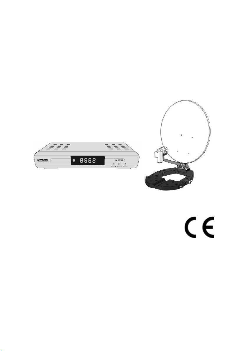
Digital Mini Satellite System SL 65/12
Operating manual
Version 1.0 GB, as of 09/01/2007
Modifications and errors reserved.
We do not assume any liability for printing errors.
Dear customer,
Having in mind an environmentally friendly behaviour we ask you to
switch off your receiver after usage.
With this, you will contribute to the protection of the environment and
save money.
2
Page 3

Preface
Preface
This operating manual will help you in the
• appropriate
• safe
usage of the digital mini satellite system SL 65/12, hereafter called
the “satellite system” in short.
The satellite system is packed in a transport case and consists of:
• a digital satellite receiver SL 65/12 (receiver unit), hereafter
called the receiver in short and
• the antenna unit with installation material.
We assume that users of the satellite system have overall knowledge
regarding handling audio and video equipment.
Every person who
• installs,
• connects,
• operates,
• cleans
• disposes of
this satellite system must be familiar with the entire content of this
operating manual. Always keep this operating manual in the
proximity of the satellite system.
Style features
Specific style features have been given in different sections of the
operating manual. Thus, you can easily differentiate whether it
concerns
normal text,
• enumerations or
actions.
3
Page 4

Contents
Contents
Preface...............................................................................................3
Style features .................................................................................... 3
Contents ............................................................................................ 4
Safety instructions ...........................................................................7
Basic safety instructions......................................................... 7
Appropriate use .............................................................................. 10
Scope of supply ..............................................................................12
Description ......................................................................................14
Quick guide ..................................................................................... 18
Antenna installation .......................................................................19
Installation of the antenna .............................................................19
Installation options.........................................................................22
Receiver connection.......................................................................31
LNB cable installation ....................................................................32
Connection with the Scart cable ................................................... 34
Connection with the Cinch cable .................................................. 36
Connection of an audio-digital receiver ....................................... 36
Direction of the antenna.................................................................38
Correct location .............................................................................. 38
Rough direction of the antenna ....................................................40
Getting started ................................................................................ 43
Remote control ...............................................................................43
Receiver...........................................................................................44
Fine tuning of the antenna.............................................................45
4
Page 5

Contents
Operation.........................................................................................48
Screen-inlays while switching channels ...................................... 48
User interface on the TV screen....................................................50
Menu structure................................................................................51
Menu navigation .............................................................................52
Channel (symbol: TV).....................................................................53
Installation (symbol: Satellite antenna) ........................................ 58
System Setup (symbol: gearwheel) .............................................. 62
Tools (symbol: tools) .....................................................................66
Software update via satellite .........................................................67
Keys with special functions ..........................................................68
Switch between TV and SAT .........................................................68
Switch between TV and radio ........................................................68
ZOOM ...............................................................................................68
LIST ..................................................................................................68
AUDIO .............................................................................................. 69
EPG .................................................................................................. 69
TEXT.................................................................................................69
M/P....................................................................................................70
MUTE................................................................................................70
FAV...................................................................................................70
RECALL ........................................................................................... 71
INFO - acoustic signal for directing the satellite antenna .......... 71
0 – Sleep timer ................................................................................71
PAUSE..............................................................................................71
Dismantling the satellite system ...................................................72
Cleaning...........................................................................................73
Maintenance ....................................................................................73
Tips and tricks/Trouble shooting ..................................................74
Disposal...........................................................................................77
Specifications .................................................................................78
Manufacturer ...................................................................................80
Guarantee ........................................................................................80
Declaration of conformity ..............................................................81
Index.................................................................................................82
5
Page 6

Contents
Glossary ..........................................................................................84
6
Page 7

Safety instructions
Safety instructions
Please read the safety instructions carefully before operating the
satellite system .
Please follow all warnings and instructions on the equipment and in
the operating manual.
Basic safety instructions
Electrical connection
• Do not expose the receiver to rain or any kind of humidity to avoid
risk of fire and electric shock.
• Never open the casing. Otherwise, there is a risk of electric
shock.
• Connect the receiver only to the power source installed by an
expert. It is either:
- for an external power pack:
a 100–240 V, 50-60 Hz mains socket as per specifications or
- for a 12 V cable:
a 11 V – max. 14 V DC supply as per specifications.
• Ensure that the total power consumption by the antenna
connection of the receiver does not exceed “LNB IN” 300 mA.
• Pull the external power pack or the 12 V cable out of the mains
socket if you will not use the device for a longer period of time.
Only pull at the external power pack or at the head piece of the 12
V cable, not at the cable itself.
• In case of a storm, pull the external power pack or the 12 V cable
of the receiver out of the mains socket.
• In case of a storm, pull the LNB-cable out of the receiver.
• If foireign bodies or fluids enter the receiver, immediately pull out
the external power pack or the 12V cable out of the socket. Ask a
qualified person to check the equipment before operating it once
again. Otherwise, there is a risk of electric shock.
• Do not bend or crimp any cable.
7
Page 8

Safety instructions
• If a cable used for mains supply is damaged, the receiver must be
repaired by an expert before reusing it. Otherwise, there is a risk
of electric shock.
• Never allow children to operate the receiver or to play with the
antenna unit unless supervised.
• Always ask qualified personnel to carry out maintenance jobs.
Otherwise, you are putting yourself and others at risk.
• Disconnect the receiver from the power source in case of
operational disruptions.
• Ensure that the power source is easily accessible.
• Spare parts must be ordered directly from the manufacturer
• Modifications of the device lead to an extinction of the
manufacturer’s liability.
• Remove protection film.
Correct position
• Place the receiver on a stable and even base.
• Use the receiver only with adequate climatic conditions.
• Avoid proximity to:
- heat sources, like e. g. heaters,
- naked flames, like e. g. candles,
- devices with strong magnetic fields, like e.g. loudspeakers.
- Never place receptacles filled with liquid (vases) on the
receiver.
• Avoid direct sunlight and places with an extremely high amount of
dust.
• Never cover ventilation slits. Provide for sufficient ventilation by
maintaining a safety distance of 5 cm to other objects.
• Do not place any heavy objects on the receiver.
• Humidity may settle in the receiver if it is brought into hot
surroundings from a cold one. In this case, wait for about an hour
before operating the equipment.
• Arrange all cables in such a manner that no-one steps or trips
over them.
8
Page 9
Safety instructions
• The antenna unit is not suitable for operating in case of high wind
pressures. Do not expose it to strong wind.
Correct battery handling
• Batteries may contain toxic agents. Ensure that batteries are not
within the reach of children. Children may eat and swallow
batteries.
• Batteries that are getting discharged may damage the remote
control. If the receiver is not in use for a longer period of time,
remove the batteries from the remote control.
• Batteries may contain toxic agents. Therefore, dispose of the
batteries immediately in an ecologically accepted manner
according to the prevailing statutory regulations. Never throw the
batteries into normal household waste.
• Never expose the batteries to open fire or strong heat, as
otherwise there is a danger of explosion.
• Replace the batteries always by batteries of the same type.
Explanation of the safety instructions
The following categories of safety instructions are included in the
operating manual:
Danger!
Instructions with the word DANGER give a warning against
possible personal injuries.
Caution!
Instructions with the word CAUTION give a warning against
possible material or environmental damages.
These instructions contain special information for the
commercial use of the satellite system.
9
Page 10
Safety instructions
Appropriate use
The satellite system receives digital satellite channels for private use.
It is exclusively meant for this purpose and must only be used for the
same. This also includes paying attention to all information contained
in these operating instructions, especially the safety instructions.
Due to its user-friendly installation and disassembly, the satellite
system is ideal for mobile use (camping or caravans). As there are
diverse installation options, the system can be used in many places:
• on/at tables
• at masts
• at walls
• on lawns
• on crates
• etc.
Please observe the following safety instructions for each kind of
installation:
Please observe all prohibitions or information of the local
administration (if any).
Danger!
Do not expose the satelite system to high loads due to wind
pressures, e.g.
- installation in great heights (balcony railings)
- storm (wind speed > 75 km/h)
In case of non-observance, there is a risk of damage to property
and personal injury.
Wind speed
(km/h)
Load of the
antenna due to
wind pressure (N)
40 50 60 70 80 90 100 110
11.27 17.64 25.48 34.59 45.28 57.23 70.66 85.55
10
Page 11

Safety instructions
Caution!
The maximum bending moment of the satellite system is 15.30 Nm.
Please make sure during installation that the fixation is able to
withstand this pressure.
Do not install the satellite system at places with difficult accessibility.
Mount the satellite system only at places at which it will be easily
accessible for you without any danger. Make sure that in case of
need you will always be able to remove the system.
Any other use is considered to be improper and may lead to material
damages and even personal injuries.
Amongst others, information on wind speed is available on the
Internet.
Do not leave the satellite system unattended.
COMAG Handels AG does not bear any liability for damages caused
due to improper use.
11
Page 12
Scope of supply
Scope of supply
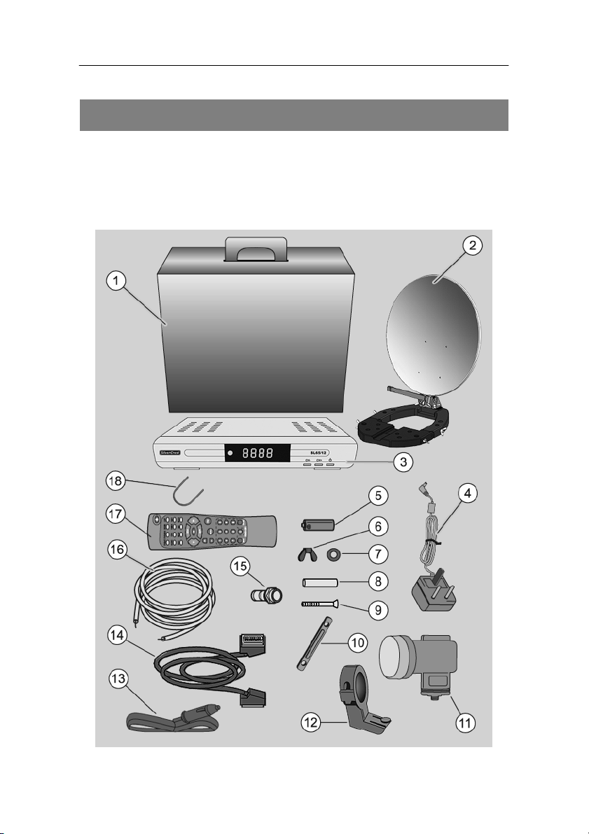
Check the scope of supply after your purchase.
The receiver, the remote control, the 2 batteries, the external
power pack and the 12V cable for the cigarette lighter are
included in a box. We recommend packing these pieces again in
the box when dismounting the system.
12
Page 13

No. Pieces Description
without
1 Operating manual
figure
1 1 Transport box
2 1 Antenna with base
3 1 Digital satellite receiver SL 65/12
4 1 External power pack
5 2 Battery for the remote control
6 2 Wing nut for U bracket
7 2 Plain washer for U bracket
8 4 Dowel for wall bracket
9 4 Screw for wall bracket
10 2 Lateral rods
11 1 Single universal LNB
12 1 LNB-bracket
13 1 12V cable for cigarette lighter
14 1 Scart cable
15 2 F connector
16 1 10m coaxial cable (not pre-converted)
17 1 Remote control
18 1 U bracket
Scope of supply
13
Page 14

Description
Description
You can receive uncoded (free-to-air) digital satellite channels with
the satellite system without depending on a fix mounted satellite
antenna. The mobile antenna allows you to receive signals at
different places, like e.g. on a camping site. With the mounting parts,
the antenna can be installed e.g. on a balustrade, a mast or a wall.
Naturally, you can also connect the receiver to a fix installed satellite
antenna.
It is not necessary to set the receiver yet. The most important
broadcasting stations and satellites have already been preset.
The following satellites have been preset by the factory:
• Astra 19.2E
• Hotbird 13.0E
• Türksat 42.0E
• Sirius2 5.0E
• Amos/Atlantic4-5W
• Astra 28.2E
• HispaSat 30W
• Eutel W3A 7E
• Eutel W2 16E
• Hellasat 39E
The antenna has to be directed towards the desired satellite.
The receiver will scan for further new broadcasting stations as soon
as you initiate the automatic scan of broadcasting stations for this
satellite. Satellites not preset may be added.
Please note that the reception of the preset satellites
depends on the location. The satellite system has been
designed for mobile use. Therefore not at each location all
preset satellites can be received due to the size of the
antenna. Please compare the elevation table in the section
„Rough direction of the antenna“ on page 42.
14
Page 15

Description
All receiver settings can be done easily using the user interface
(menu)) on the TV screen.
The multilingual user interface supports following languages:
• German
• Italian
• Spanish
• Greek
• English
• Polish
• Czech
• Slovak
• Hungarian
• Danish
• French
• Swedish
• Croatian
Further features:
• Software update via satellite ASTRA 19° East or via the RS232
connection on the rear side of the device.
• Short switching time, fast boot process when switching on the
receiver
• Saves the channel last watched (Last Station Memory)
• LNB control logic (sound 0/22 kHz), max. current delivery for LNB
300 mA
• Symbol rate 1-35 MS/s and 950-2150 MHz input frequency
• Manual PID entry possible
• 3 keys at the frontage
• 4-digit LED display
• Plug & play
• External power pack 100–240 V, 50/60 Hz, output 12V; 1.0A
15
Page 16

Description
• 4,500 channel-storage locations
• Parental lock (preset password: 0000)
• 1 favorite list and 8 channel groups
• Automatic scan of broadcasting stations
• List editor for broadcasting stations
• Analogue sound output through Cinch connector (stereo), volume
adjustment possible via remote control
• Coaxial digital output (digital audio)
• 2 Euro-SCART connections for TV and video set
• Video output signal CVBS
• Loop-through-function in standby mode for the connection of an
analogue receiver
• Super fast videotext with a memory of 800 pages
• Digital radio reception, background image for radio (background
display)
• Additional channel information is displayed when the channel is
changed.
• DiSEqC 1.0, 1.2, Go-to X is supported if an appropriate antenna
unit is connected
• SWAP function (via Recall key)
• Screen aspect ratios can be set to 4:3, 16:9, and automatically
(letterbox)
• Multi-functional timer, 8x and linked with EPG, sleep timer
• Electronic Programme Guide EPG (up to 14 days in advance,
channel-dependent)
• SCPC/MCPC reception standard C/Ku-band satellites
• Automatic selection of the TV standard with video converter
• Zoom function
• Multi-picture function
• Digital satellite finder for optical and acoustic adjustment of the
antenna
16
Page 17

Description
A suitable channel editor is additionally available through
our service hotline. Then you will be able to edit the channel
lists of the receiver using your computer. Please read the
information on our website for this purpose.
Please note that under the Web address:
www.mysilvercrest.de
• current software versions (if required)
• and channel-list editing software for the PC
can be downloaded.
Should you have any questions please contact our service hotline.
17
Page 18

Quick guide
Quick guide
You must install, connect and adjust your satellite system in the
following sequence to be able to use it.
Install the antenna.
Connect the receiver to the equipment.
Install the LNB cable.
Connect the LNB cable to the antenna.
Direct the antenna roughly.
Insert the batteries in the remote control.
Connect the receiver and the equipment to the power source and
switch them on.
Set the channels using the remote control.
Direct the antenna finely if the reception quality is not
satisfactory.
If you would like to do individual settings for the receiver, invoke
the user interface on the TV screen.
Make the desired settings in the menus.
18
Page 19
Antenna installation
a
ntenn
a
Base of antenn
a
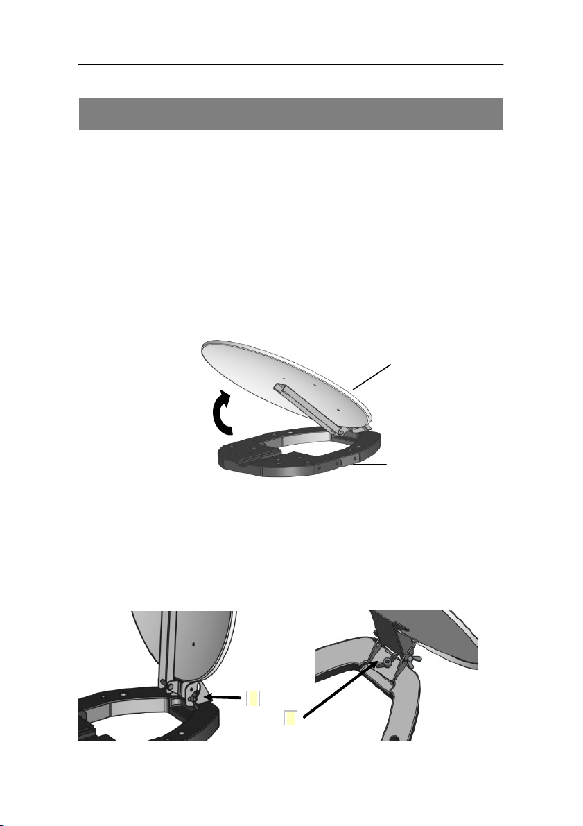
Antenna installation
The antenna consists of a few individual components and is simple
to install.
Take out the system components from the transport box.
Remove the packing material.
Installation of the antenna
Step 1: Place the antenna with its base on a suitable surface
and open it in direction of the arrow until it is in a vertical
position.
Step 2: Now, the antenna is open. For fixing the angle of
inclination of the antenna please tighten both wing nuts
(arrow 1). The adjustment of the angle of inclination is
described in section “Direction of the antenna“ on page
38. The horizontal direction (azimut) by rotating the
antenna wll be fixed with the wing nut at arrow 2.
19
Page 20
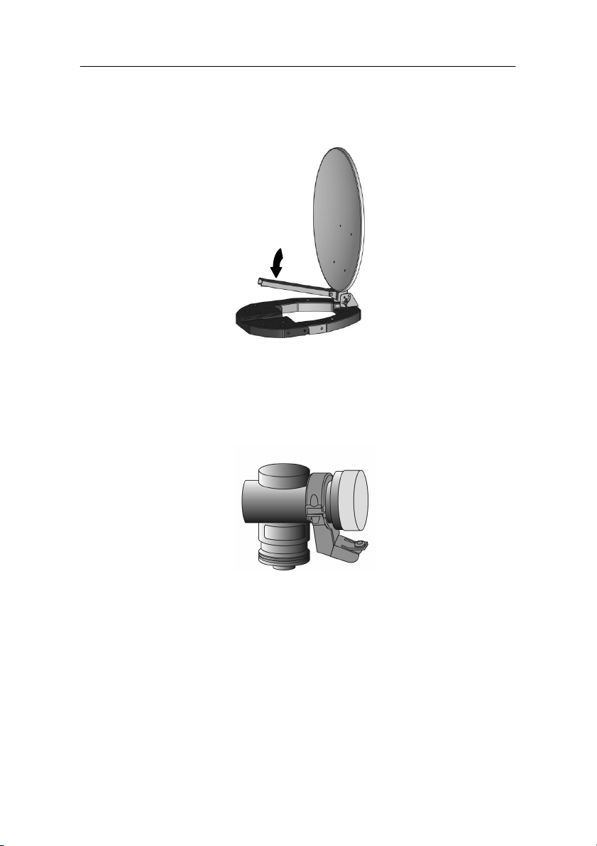
Antenna installation
Step 3: Now take the LNB arm down in direction of the arrow
until it is locked noticeably.
Step 4a: For installing of the LNB in the LNB bracket untighten
the 2 screws of the LNB bracket and remove the top
half of the LNB bracket. Then insert the LNB as shown
in the picture and fix the top cover again with the screws
and nuts. Tighten the screws uniformly.
The indication “TOP“ at the LNB must be in the middle and
face upwards.
For step 4a you will need a crosstip screwdriver (not included
in the scope of supply). Tighten the screws of the LNB bracket
only in such a way that the LNB is fixed. If you tighten them
too much, the LNB bracket could break. Additionally, the LNB
could be deformed or damaged.
20
Page 21
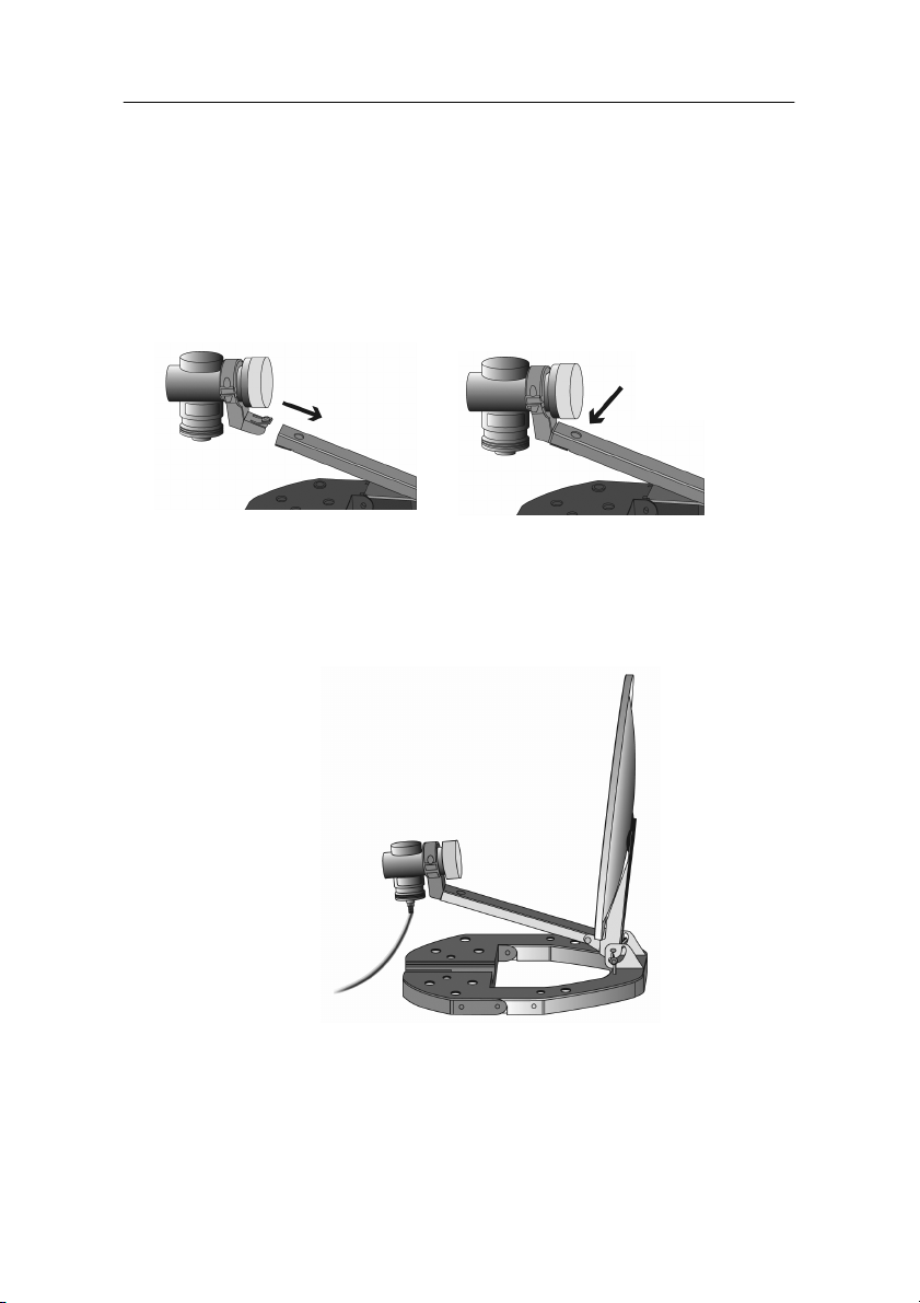
Antenna installation
Step 4b: Insert the LNBbracket in direction of the arrow as far as
it will go into the LNB arm until the LNB bracket is
locked. While you are doing this, press the clip with the
button for installation slightly down.
Step 5: Now, the antenna is completely installed. Fix the
antenna cable at the LNB. The installation of the
antenna cable is described in the section “LNB cable
installation“ on page 32.
Press button
to remove.
For dismantling the antenna carry out step 1 - 5 in reverse
order.
21
Page 22

Antenna installation
Installation options
The antenna can be set up in different ways using the installation
material provided.
For clarification, the installation options are illustrated in the pictures
below.. To make the picture less complex the antenna cable is not
illustrated here. For a complete installation of the satellite system
the cable must be fixed at the LNB.
Please observe all prohibitions or information of the local
administration (if any).
When selecting an installation place you should make sure
in any case that there are no obstacles between the
antenna and the satellite. No tree, house, pane or other
obstacles must block visibility.
As a general rule:
an obstacle may only be half the size as its distance to the
antenna.
The surface of the mounting position may get damaged
slightly for all these installation options. You can protect the
sensitive surface from scratches and pressure marks by
placing a piece of felt, cardboard or similar on it.
22
Page 23
Antenna installation
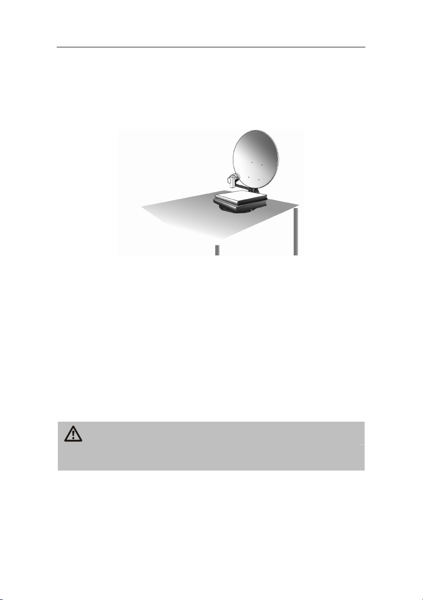
Installation on a table
Place the installed antenna on a table. The base of the antenna
must be entirely placed on the table surface.
After the cabling of the satellite system the antenna can be
directed to the desired satellite. For this, please proceed as
described in the section “Direction of the antenna“ on page 38.
Put sufficient weight on the base, e.g. books, to avoid a
tipping over of the antenna by an unintentional external
influence (e.g. wind).
The antenna can alternatively be installed at a table leg.
For doing this, please proceed as described in the section
“Installation on a mast.
Should the table be in a room, make sure to put it near an
open window to reach an optimum reception.
Caution!
You can protect the sensitive surface from scratches and pressure
marks by placing a piece of felt, cardboard or similar on it.
23
Page 24
Antenna installation
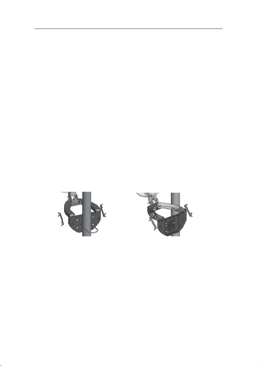
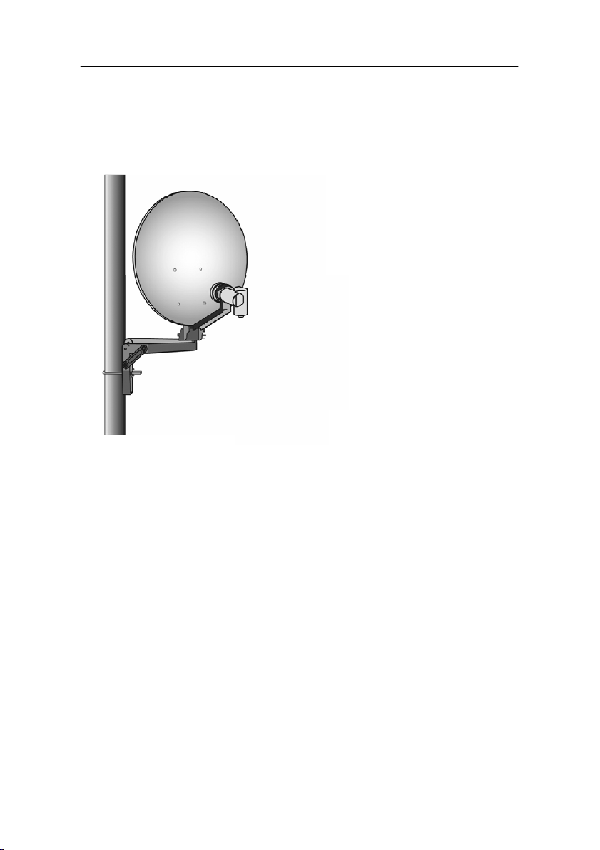
Installation on a mast
First of all, rotate the antenna by 180° so that the LNB will face
away from the antenna base.
Now, flap down the antenna base by 90° using the articulation.
Then fix the lateral rods with the wing nuts at the left and right
side of the base to get the required stability. The cavities of the
lateral rods must face towards the inside of the base. Now. the
lateral rods rest directly on the base. The spring ring and the plain
washer must be placed between the lateral rods and the wing
nuts. Here, the plain washer rests on the respective lateral rod.
The spring ring must be placed between the plain washer and the
wing nut.
For fixing the base on the mast, place the U bracket around the
mast and lead it through the corresponding holes of the base.
Now tighten the wing nuts uniformly.
The maximum diameter of the mast must not exceed
60mm.
24
Page 25
Antenna installation
After the cabling of the satellite system the antenna can be
directed to the desired satellite. For this, please proceed as
described in the section “Direction of the antenna“ on page 38.
For achieving a safe installation on the mast, please make
sure that the plain washers are always placed between the
wing nuts of the U bracket and the base.
25
Page 26
Antenna installation
Installation on a wall
First of all, rotate the antenna by 180° so that the LNB will face
away from the antenna base.
Now, flap down the antenna base by 90° using the articulation.
Then fix the lateral rods with the wing nuts at the left and right
side of the base to get the required stability. The cavities of the
lateral rods must face towards the inside of the base. Now, the
lateral rods rest directly on the base. The spring ring and the plain
washer must be placed between the lateral rods and the wing
nuts. Here, the plain washer rests on the respective lateral rod.
The spring ring must be placed between the plain washer and the
wing nut.
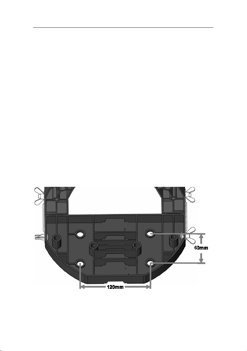
Now, put the base on the place at which it is to be installed and
mark the position of the four bore holes. In the picture you can
see the holes and the boring distances for the screws:
Drill the four boreholes. The size of the bore holes must
correspond to the dowels included in the scope of supply.
26
Page 27

Antenna installation
Wrench size: 13; depth of hole (brick or concrete): 55mm;
drill: Ø 10mm
For an installation at a wood truss the pre-drilling must not
exceed a diameter of 4mm (Ø) and a depth of 20mm.
Please do not use dowels here.
Countersink the four steel dowels into the boreholes.
Put the base on the place of its installation and fasten it with the
four screws.
For achieving a safe wall installation , a plain washer is
included for each screw supplied.
After the cabling of the satellite system the antenna can be
directed to the desired satellite. For this, please proceed as
described in the section “Direction of the antenna“ on page 38.
Caution!
Consider that the installation on a wall can be compared with a fix
installation. Therefore, it can alter the surface of the wall.
Before boring make sure that no conductions, tubes, etc. will be
damaged.
27
Page 28

Antenna installation
Installation on lawns
Place the installed antenna on the lawn.
You can fix the base of the antenna e.g. with tent pegs (see
arrows) on the lawn to protect it against external influences (such
as wind, displacement or tipping over).
After the cabling of the satellite system the antenna can be
directed to the desired satellite. For this, please proceed as
described in the section “Direction of the antenna“ on page 38.
28
Page 29

Antenna installation
Installation on a crate
First of all, rotate the antenna by 180° so that the LNB will face
away from the antenna base.
Now, flap down the antenna base by 90° using the articulation.
Then fix the lateral rods with the wing nuts at the left and right
side of the base to get the required stability. The cavities of the
lateral rods must face towards the inside of the base. Now, the
lateral rods rest directly on the base. The spring ring and the plain
washer must be placed between the lateral rods and the wing
nuts. Here, the plain washer rests on the respective lateral rod.
The spring ring must be placed between the plain washer and the
wing nut.
For fixing the base on the crate, place the U bracket on the crate
as shown in the picture. Now, lead the U bracket through the two
corresponding holes of the base. Tighten the wing nuts uniformly.
The maximum diameter of the bar at which the base is fixed
must not exceed 60mm.
After the cabling of the satellite system the antenna can be
directed to the desired satellite. For this, please proceed as
described in the section “Direction of the antenna“ on page 38.
29
Page 30

Antenna installation
To achieve a higher stability, the bottles in the crate should
be filled.
For achieving a safe installation, please make sure that the
plain washers are always placed between the wing nuts of
the U bracket and the base.
30
Page 31

Receiver connection
Receiver connection
The receiver is connected with your satellite antenna by means of a
coaxial cable. If necessary, you will have to prepare a coaxial cable
before connecting the receiver.
Caution!
Connect the receiver to the mains supply only after you have
connected it to all equipment and the antenna properly.
Otherwise, the receiver can suffer damages.
The wire netting and the inner core of the coaxial cable carry
current during operation.
Usage for camping or in caravans:
The receiver can also be operated with 12V (i.e. 11-14V,
e.g. solar panel, vehicles). Use a 12V cable for this
purpose.
Caution! In case of vehicles with an on-board power-supply
voltage of 24V (e.g. freight vehicles), please use a 24V/12V
DC-DC converter. Otherwise, the receiver could suffer
damages. You will lose your guarantee in case of nonobservance.
31
Page 32

Receiver connection
LNB cable installation
(Cp. the installation diagram on the next page)
For the installation of the F connectors on the coaxial cable you will
need a knife (ideally a wire stripper) and side cutting pliers.
When stripping the isolation, neither the inner core or the
foil nor the wire netting must be damaged.
Cut 8 mm of the coaxial cable at each end up to the inner core.
Carefully cut 10 mm of the outer insulation so that the wire netting
is exposed.
Turn the wire netting backwards and wind it over the outer
insulation in such a manner that it does not touch the inner core.
Remove the inner insulation together with the foil placed over it
up to 2mm before reaching the wire netting.
Caution!
The wire netting and the foil must not touch the inner core. The foil
must enclose the inner insulation and must not be damaged.
Rotate the F connector onto the turned-back wire netting untill the
connector touches the inner insulation.
The wire netting must not protrude from the back of the
connector end.
Cut the inner core with a cable cutter in such a manner that it
projects maximum 1 mm from the connector.
32
Page 33

Installation diagram
Receiver connection
Fasten the F connector of the coaxial cable onto the “LNB IN”
antenna connection of the receiver. Fasten the other end of the
coaxial cable on the LNB.
33
Page 34

Receiver connection
Connection with the Scart cable
Insert the Scart cablel in the Scart socket “TV” on the receiver.
Connect the Scart cable to the TV set. Follow the operating
manual of the TV set.
Insert the Scart cable in the Scart socket “VCR” of the receiver if
you want to connect a video set.
Connect the Scart cable to the video set. Follow the operating
manual of the video set.
Keep in mind that only one Scart cable is included in the
scope of supply.
34
Page 35

Connection diagram
Receiver connection
35
Page 36

Receiver connection
Connection with the Cinch cable
Connect the Cinch connectors of the Cinch cable to the “AUDIO
R” and “AUDIO L” sockets of the receiver if you want to connect a
stereo system.
Caution!
Never connect the Phono input of your stereo system to the
receiver; it may damage your stereo system.
Strictly follow the instructions for connecting the Cinch cable given
in the operating manual of your stereo system.
The Cinch cable is not included in the scope of supply.
Connection of an audio-digital receiver
If you want to use 5-channel audio transmission (Dolby digital
sound/AC3), you must connect your audio-digital receiver to the
coaxial output of the receiver.
Caution!
Please follow strictly the information regarding connection in the
operating manual of your audio-digital receiver.
Your TV set need not be switched on for radio reception.
36
Page 37

Receiver connection
Connection of the coaxial digital output
Insert the coaxial cable in the “COAXIAL” socket or the receiver.
Connect the coaxial cable to the audio-digital receiver.
Connection diagram
The coaxial cable is not included in the scope of supply.
37
Page 38

Direction of the antenna
Direction of the antenna
Correct location
The most common satellites are in southeastern direction, e.g.
Astra 19,2° East, Eutelsat Hotbird 13° East.
The direction of the reception / antenna is determined by two angles:
• the horizontal azimuth angle = haa
• the vertical elevation angle = vea
When searching the southern direction, the position of the
sun might help you. During summer time in Germany, the
sun is exactly in southern position at 12 am noon and during
winter at 1 pm.
The following picture shows the angle of 90° between the cardinal
points South (S) and East (E) at which nearly all common satellite
positions, such as Astra 19,2° East and Eutelsat Hotbird 13° East
can be found. This is called the horizontal azimuth angle.
38
Page 39

Direction of the antenna
Depending on which satellite you wish to receive, there must be free
sight without any obstacles in this angle. This must be especially
ensured with the installation on a wall. Please make sure that you
are able to rotate your antenna in a manner that it does not touch the
house wall.
The saltellite system must not touch any wires (such as aerial
wires). There is danger of life.
Example for an installation on a wall:
Translation of text in the picture:
Hindernis = obstacle
Mindestabstand = minimum distance
Ost = East
Süden = South
Danger of electric shock!
Please make sure that there are no obstacles between the
antenna and the satellite. No tree, house or other obstacles
must block visibility. As a general rule:
an obstacle may only be half the size as its distance to the
antenna. This is applicable for all kinds of installation.
39
Page 40

Direction of the antenna
Rough direction of the antenna
You must connect the LNB cable to LNB before directing the
antenna.
While connecting the LNB cable, the receiver must not be
connected to the mains supply.
Caution!
Screw the F plug on the LNB connection.
Pull the plastic cover of the LNB over the LNB-connection.
After installation, direct the antenna towards the satellite through
which you would like to receive signals. While doing this, set the
horizontal azimuth angle. The azimuth scale (arrow) will help you
with this. The distance between two marks is approx. 6°.
40
Page 41

Direction of the antenna
1
2
If you have directed the antenna towards your desired satellite,
you must set the elevation angle (vertical elevation angle). The
scale (arrow 1) will serve you as an orientation for setting the
elevation angle.
Unscrew the wing nuts (arrow 2) for setting the elevation angle.
Move the antenna carefully back or forward by the required
degree.
The table on the next page will serve you as an orientation
for setting the corresponding elevation angle depending on
the location and the satellite to be received.
The satellite system has been designed for mobile use.
Therefore not at each location all satellites can be received
due to the size of the antenna. For this, we presume a
horizontal installation of the antenna.
Tighten the wing nuts as soon as the desired elevation is
attained.
41
Page 42

Elevation table
Astra 1B
Hotbird 13E
Türks at 42E
Sirius2 5.0E
AMOS/ATLA
ASTRA28E A
HISPASAT
EUTEL W 3A
EUTEL W 2
HELLA S AT
Athen-45,00°
42,00°
----43,00°
42,00°
43,00°
Barcelona
39,00°
41,00°
--41,00°
35,00°
32,00°
---
Bratislava
34,00°
34,60°
-
33,00°
31,00°
34,00°
--34,00°
31,00°
Budapest
35,50°
35,50°
31,00°
34,00°
31,00°
----32,00°
Dublin
25,00°
26,60°
-
28,00°
29,00°
21,50°
25,00°
---
Hamburg
28,00°
28,80°
22,00°
29,00°
-
26,60°
19,00°
---
Kopenhagen
26,30°
26,60°
-
26,00°
-
25,00°
---
-
London
28,40°
25,40°
-
31,00°
31,00°
25,40°
24,80°
---
Madrid
37,70°
40,00°
-
42,00°
43,00°
33,00°
36,00°
---
Mailand
36,70°
37,50°
28,50°
-
36,00°
-
25,00°
--30,00°
Marseille
38,00°
39,50°
--39,00°
35,00°
28,00°
---
München
34,20°
34,70°
27,00°
34,00°
32,50°
32,00°
22,00°
35,00°
34,60°
-
Paris
32,00°
33,00°
-
34,00°
33,00°
28,70°
26,00°
32,00°
33,00°
-
Prag
33,00°
32,00°
-
31,00°
30,00°
--32,00°
32,00°
28,00°
Rom
41,00°
42,00°
--39,00°
-
25,00°
41,00°
42,00°
35,00°
Stockholm
22,00°
23,00°
-
22,00°
20,00°
22,00°
-
22,00°
23,00°
-
Warschau
30,00°
29,00°
-
28,00°
25,00°
--29,00°
30,00°
-
Zagreb
37,00°
37,00°
31,00°
36,00°
34,00°
---
37,00°
33,00°
19.2E
42
NTIC 4-5W
ST
30W
7E
16E
39E
Direction of the antenna
Page 43

Getting started
Getting started
Remote control
Two Micro type batteries are required for the remote control:
LR 03/AAA/1.5 V
Open the battery compartment.
Insert two batteries into the battery compartment paying attention
to the indicated polarities and push the cover of the battery
compartment carefully until it is locked.
Replace discharging batteries on time. Otherwies, the sending
capacity of the remote control will be too low.
Always replace both batteries simultaneously and use batteries of
the same type.
Check the batteries of your remote control at least once a year.
If one of the batteries has leaked, wear protective gloves and
clean the battery compartment with a dry cloth.
Caution!
Batteries may contain toxic agents that are hazardous to health
and environment. Therefore, dispose of the batteries immediately
according to the prevailing statutory regulations. Never throw the
batteries into normal household waste.
The remote control transmits infrared signals to the receiver. Please
refer to the overview of the remote control for the functioning of the
keys.
Point the remote control towards the front side of the receiver and
slightly press the corresponding key once.
43
Page 44

Getting started
Receiver
Caution!
Check the proper connection of all devices and of the antenna
before connecting the external power pack or the 12 V cable of
the receiver to the power source and starting the receiver.
Insert the mains plugs of the connected equipment in the mains
socket and switch it on.
Switch on the AV channel of the TV set.
Insert the power pack of the receiver in the mains socket. The
device is in normal mode. The LED display shows the current
channel.
If you wish to operate the receiver with 12V, insert the 12V mains
cable in the “DC IN“ socket and connect it to your power source.
Caution!
In case of vehicles with an on-board power-supply voltage of 24V
(e.g. freight vehicles), please use a 24V/12V DC-DC converter.
Otherwise, the receiver could suffer damages. You will lose your
guarantee in case of non-observance.
The receiver is supplied with preset TV channels and can be used
immediately. If you want to check whether new channels are
available, enable the automatic scan in the menu item Installation on
page 58.
To switch over to the standby mode press the standby key
(red key top right on the remote control or the key at the
right side of the three keys at the face of the receiver).
The LED display of the device shows the time in the
standby mode.
44
Page 45

Getting started
Fine tuning of the antenna
The reception quality set by you in the antenna settings may not be
optimal. In this case, you must do a fine tuning of the antenna.
• Select a channel broadcasted on the satellite of your choice,
e.g. Astra1 19° East channel location 1 = ARD
• Press the “INFO” key.
• The current reception parameters are displayed. Please
have a look at the signal-quality display during the following
fine-tuning process.
• By pressing the 1 key, an acoustic signal is offered
additionally to support you during the fine-tuning process. A
stronger and higher signal indicates a better direction of the
antenna.
As soon as the signal quality has reached approx. 60%, the channel
image appears in the background. Should there be no image, you
might have directed the antenna to another satellite instead of
Astra1 19°. In this case, please proceed with the fine-tuning process
as follows until you can see an image in the background.
Initially you must set the antenna vertically approx. 1° steeper or
flatter to set the correct elevation angle.
Please keep in mind that the signal-strength indication only
shows the connection quality of the antenna to the receiver
and is not intended to be used for directing the antenna.
For this purpose, slightly unscrew both wing nuts as described in
the previous section.
Incline the antenna by approx. 1°.
45
Page 46

Getting started
When you have found a position with good reception quality, you
must tighten the wing nuts again to fix the antenna .
Slowly turn the antenna horizontally towards the right and
subsequently towards the left.
A digital satellite receiver receives the transmission signal
of the satellite with a time lag. Therefore, turn the antenna
very slowly degree by degree and wait for a few seconds in
every position.
46
Page 47

Getting started
Check the signal quality continuously.
If you cannot find an antenna setting with good signal quality,
adjust the antenna again in vertical direction by 1°.
If you cannot find an antenna setting with good signal quality,
adjust the antenna again in vertical direction by 1°.
Find an antenna setting for attaining the best possible signal
quality in this manner.
During the fine-tuning process of the antenna, the acoustic
signal indication may also help you. However, it can only be
enabled when running a manual scan.
The higher the tone the better the antenna direction.
Please write down the set elevation and azimuth angles
after having finished the fine-tuning process in order to
make it easier for you to direct the satellite system again to
the desired satellite at the same place.
47
Page 48

Operation
Operation
Screen-inlays while switching channels
When a channel is switched, an information bar appears on the
screen for 5 seconds.
In this information bar, you will find the following indications:
Channel name
Received satellite
Current date
Current time (According to the presetting in menu
Storage location
TTX symbol This symbol is displayed if the selected broadcasting station
item “Time“).
offers Teletext.
EPG
symbol
Heart
symbol
Channelgroup
symbol
Info Information on the current and the following programme
Info Information on the currently active channel list
This symbol is displayed if the selected broadcasting station
offers an electronic programme guide.
The heart symbol is displayed if you have included the
channel in your favorite list.
The corresponding channel-group symbol is displayed if you
have included the channel in your channel list. An overview of
the channel-group symbols is provided on the next page.
“Now” – “Next”
48
Page 49

Channel-group symbols
Symbol Channel group
Sport
News
Music
Movie
Shopping
Education
Leisure
Operation
Should the current programme belong to the general
channel group, no symbol will appear.
49
Page 50

Operation
1
2
3 3
User interface on the TV screen
You can do individual settings of your receiver using the menus in
the user interface. For this purpose, both the receiver and the TV set
need to be switched on and connected by a Scart cable.
Press the “MENU” key. The main menu will be displayed. By
pressing the “EXIT“ or the “MENU“ key, you can exit this menu
again. When you exit the main menu, an information bar appears on
the screen for 5 seconds.
Navigation within the menus
Top (arrow 1): menu name
(the corresponding function symbols are
displayed at the bottom)
Middle (arrow 2): sub-menu or menu items
Below (arrow 3): The information bar shows you the
keys with which you can navigate
in the current menu.
50
Page 51

Menu structure
Main menu Sub-menu Description
Channel
(symbol:
TV)
page: 53
Installation
(symbol:
Satellite
antenna)
page: 58
System Setup
(symbol:
gearwheel)
page: 62
Tools
(symbol
tools)
page: 66
TV Channel list See following text
Radio Channel list See following text
Delete all See following text
Antenna Setup See following text
Automatic Scan See following text
TP Scan See following text
Preset Scan See following text
Language See following text
TV System See following text
Channel setup See following text
Time & Timer setting See following text
OSD setting See following text
Parental Lock See following text
LNB Power See following text
Information See following text
Game See following text
Default Value See following text
Software-Update See following text
Operation
51
Page 52

Operation
Menu navigation
Use the keys “CH▲”, “CH▼”, “V+”, and “V-” to navigate within the
menus. The selected menu items are marked. Confirm your selection
with the “OK” key. By pressing the “EXIT” key you can exit the menu
again. Changes must be confirmed additionally. Apart from this, the
numerical keys are required in further sub-menus.
Example: Setting the receiver to summer time.
Press the “MENU“ key, select System Setup, then go to Time &
Timer setting, press the “OK” key, enter Time and press the “OK” key
again. Set “GMT+02:00“ in the item GMT Offset. Quit the menu by
pressing the "EXIT“ key.
In each menu, an information bar will be indicated
containing all selection options.
Setting for Central Europe:
Summer time: GMT+02:00
Winter time: GMT+01:00
52
Page 53

Operation
Channel (symbol: TV)
Sub-menu Description
TV Channel list 1 Favorite, 2 Move, 3 Find, 4 Sort, 5 Edit, 6 Type,
▲▼Select, V- V+ Group, OK Enter, EXIT Exit.
Radio Channel
list
Delete all Deletion of the complete channel list.
1 Favorite
By pressing 1 key you can determine your favourites. Next to the
corresponding channels, a heart symbol will be displayed.
2 Move
By pressing 2 key, the move symbol will appear behind the marked
channel. By pressing the keys CH▲ and CH▼, the channel will be
moved to the desired position. The procedure must be confirmed
with OK.
3 Find
Channel-scan function. By entering letters in the appearing
keyboard, a filtered channel scan is possible. By pressing the keys
CH▲, CH▼, V- and V+, you can mark the desired letter. Confirm the
marked letter by pressing the OK key.
4 Sort
Sorting of the complete channel list according to the offered options.
The list must be confirmed with OK. As long as the existing list has
not been overwritten, the last status before confirming can be
restored.
as indicated above
For this purpose: Enter password (factory setting 0000)
and confirm warning message with Yes.
53
Page 54

Operation
5 Edit
After entering the password (factory setting 0000), new selection
options will appear.
1 Delete
By marking with the 1 key, selected channels can be marked to be
deleted. Please confirm selection and safety message by pressing
the "OK“ key.
2 Skip
By marking with the 2 key, selected channels can be marked to be
skipped. Please confirm selection and safety message by pressing
the "OK“ key. Then, the selected channels are skipped when
zapping. A direct input is still possible.
3 Lock
By marking with the 3 key, selected channels can be marked to be
locked. Please confirm selection and safety message by pressing the
"OK“ key. Then, the selected channels require the entry of a
password (parental lock).
This option is not available in the favorite list or a channel
group.
Sub-menu Description
Edit 1 Delete, 2 Skip, 3 Lock, 4 Edit,
5 Create, 6 Del all, ▲▼Select, V- V+ Group, P+PPage, EXIT Exit.
54
Page 55

Operation
4 Edit
By pressing the 4 key, an editing menu will be displayed. Here, you
can change the individual parameters as desired.
Option Description
Name Changes the name of the currently selected channel.
By pressing the OK key, an editing mask will be
displayed. By pressing the keys CH▼, CH▲, V- and V+,
the curser can be moved over the keyboard. The
selected field is marked yellow. To select it press the OK
key. The cursor jumps to the next place.
Select the symbol group with the keys 1, 2 and 3 of the
remote control.
For deleting a symbol mark the “DEL“ field and press the
OK key. Select the "OK" field as soon as the channel
name is complete and press the OK key to confirm. The
changed channel name will be accepted.
If you want to exit the keyboard without any change,
press the EXIT key or markt the “Cancel“ field and press
the OK key to confirm.
Video PID Video PID input with the 0-9 keys of the remote control
Audio PID Audio PID input with the 0-9 keys of the remote control
PCR PID PCR PID input with the 0-9 keys of the remote control
Save To exit with saving changes select save and confirm by
pressing the OK key.
Exit To exit without saving changes select cancel and
confirm by pressing the OK key.
55
Page 56

Operation
5 Create
By pressing the 5 key, the create menu will be displayed. Here, a
new channel can be created.
Option Description
Satellite Satellite selection
(example: Astra1 19° East)
TP Index Selection of the created transponder on the selected
satellite.
TP Frequency Data corresponding to the selection of the created
transponder.
Symbol Rate Data corresponding to the selection of the created
transponder.
Polarity Data corresponding to the selection of the created
transponder.
Name Determination of the channel name.
By pressing the OK key, an editing mask will be
displayed. By pressing the keys CH▼, CH▲, V- and V+,
the curser can be moved over the keyboard. The
selected field is marked yellow. To select it press the OK
key. The cursor jumps to the next place.
Select the symbol group with the keys 1, 2 and 3 of the
remote control.
For deleting a symbol mark the “DEL“ field and press the
OK key.
Select the "OK" field as soon as the channel name is
complete and press the OK key to confirm. The changed
channel name will be accepted.
If you want to exit the keyboard without any change,
press the EXIT key or markt the “Cancel“ field and press
the OK key to confirm.
Video PID Video PID input with the 0-9 keys of the remote control
Audio PID Audio PID input with the 0-9 keys of the remote control
PCR PID PCR PID input with the 0-9 keys of the remote control
56
Page 57

Operation
Save To exit with saving changes select save and confirm by
pressing the OK key.
Exit To exit without saving changes select cancel and
confirm by pressing the OK key.
6 Del(ete) all
Via the 6 key you can mark all channels to be deleted. Thereafter,
individual channels can be deselected again by pressing the 1 key.
Please confirm selection and safety message by pressing the "OK“
key.
6 Type (channel group)
Here, you can assign selected channels to determined channel
groups (types) as desired. Please confirm selection and safety
message by pressing the "OK“ key. You can exit the menu by
pressing the "EXIT“ key.
57
Page 58

A
ll = encrypted and unencrypted
Installation (symbol: Satellite antenna)
Sub-menu Description
Operation
Antenna setup
Auto Scan
(unique function
that can be used
without any
previous
knowledge),
Satellite Satellite selection
(example: Astra1 19° East)
LNB type Select LNB type
(default setting is Universal)
22K 22KHz activation
(Note: with the LNB type Universal
activation occurs automatically)
DiSEqC Select DiSEqC level
DiSEqC switch Select DiSEqC command
Example:
Astra and Hotbird double reception
Astra = 1 / 4
Hotbird = 2/ 4
Disable for positioner) Not enabled
Positioner By pressing the “OK“ key you will go
to DiSEqC positioner menu. Please
refer to the operating manual of your
DiSEqC motor for help.
Polarity Horizontal, vertical, H/V (automatic
operation)
Here you can scan a selected satellite (example: Astra1
19° East) completely to search for new channels. For this
purpose, no special information is needed. You can
choose between free-to-air channels and all TV and radio
channels.
The procedure is initiated with "Scan“.
The signal strength and quality is displayed permanently.
Satellite Selection of the satellite to be
scanned
Scan mode
58
Page 59

Operation
TP Scan (manual
channel scan)
channels
Free = only unencrypted channels
Scan Channel Selection between TV and radio or
only TV or only radio
Search Start scan by pressing the OK key.
The channels found are added.
With this scanning function, you can scan the preset
frequencies (transponders) individually. The transponder
data can be changed manually.
The procedure is initiated with "Scan“.
Satellite Selection of the satellite to be
scanned
TP Index
Frequency selection
The selection options are displayed
1 Add, 2 Delete, 3 Del all
See following table for TP Index.
TP Frequency Setting of the frequency
Symbol Rate Setting of the symbol rate
Polarity H = horizontal, V = vertical
Scan Mode all = encrypted and unencrypted
channels
Free = only unencrypted channels
Preset Scan
Search Start scan by pressing the OK key.
The channels and frequency found
are added.
Scanning of preset frequencies (transponders). (Normal
automatic scan))
Satellite Selection of the satellite to be
scanned
Scan mode all = encrypted and unencrypted
channels
59
Page 60

Operation
Scan Channel Selection between TV and radio or
Search Start scan by pressing the OK key.
Free = only unencrypted channels
only TV or only radio
60
Page 61

Operation
Table for the TP Index
No. Sub-menu Description
1 Add Create new frequency (transponder):
Menu item TP: Frequency: set desired frequency
Menu item Polarity: set desired polarity
The new frequency (transponder) is created after
execution.
When exiting the menu confirm the safety
message by pressing the OK key. Only after
confirmation the new frequency will be created.
For scanning the newly created frequency, initiate
the menu item Scan.
2 Delete Delete the selected transponder. When confirming
the safety message, the transponder and all
channels on it will be deleted.
3 Del(ete) all When confirming the safety message, all
transponders and all channels on them will be
deleted.
61
Page 62

System Setup (symbol: gearwheel)
Sub-menu Description
Operation
Language
TV System
Channel setup
Language Selection of menu language (OSD)
First Audio Preselection of the audio language
(if offered by the broadcasting
station)
Second Audio Preselection of the audio language
(if offered by the broadcasting
station)
Display Mode Selection of the transmission system;
Default selection: Auto
Aspect Mode Selection of the aspect ratio;
Default selection: 4:3 Letterbox
Startup channel: Determination of the desired TV or radio
channel appearing when switching on the receivers
Boot on
Channel
Mode TV = the startup channel is a TV
Startup
Channel
Enable / disable
channel
Radio = the startup channel is a radio
channel
By pressing the OK key, a channel
list will be displayed for selecting the
startup channel. Confirm the selected
channel by pressing the OK key.
Time & Timersetting
Time Optional input of time and time
zones.
See following table for time
setting.
Timer See following table for timer
setting.
62
Page 63

Operation
OSD Setting
Menu Style Setting of menu colour
Subtitle Display Enabling of subtitles
OSD Timeout Menu inlay time (OSD timeout)
OSD
Menu transparency
Transparency
Parental Lock
(PasswordSettings)
Load Default
OSD Setting
The default password is 0000
Menu Lock Disabling of password input in the
Channel Lock Disabling of password input for
The default OSD setting can be
restored
Installation menu
locked channels (parental lock)
New Password Input of a new password. (Make sure
you will remember the new password)
Confirm
Confirm new password.
Password
LNB Power Enabling and disabling LNB power. ON is preset.
63
Page 64

Operation
Table for time setting
Sub-menu Description
GMT Usage Enable / disable
GMT Offset Setting of the location-dependant divergence to
Greenwich Mean Time
Date Enabled if sub-menu “GMT Usage“ is disabled:
Time input with the 0-9 keys of the remote control
Time Enabled if sub-menu “GMT Usage“ is disabled:
Time input with the 0-9 keys of the remote control
Time Display Enabling / disabling of the time display on the TV screen.
If GMT Usage is enabled, time in the standby mode on the
front panel of the receiver is set automatically.
64
Page 65

Operation
Table for timer setting
Sub-menu Description
Timer Number Selection of timer number 1-8.
Timer Mode Repetition (once, daily, weekly, monthly, yearly, off). With
the setting “Off“, the timer will be disabled.
Timer Service Switching between programme timer (channel) and
reminding function (message).
Wakeup Channel With the timer service setting “Message“.
you have following options: Birthday, Anniversary, and
General
With the timer service setting “Channel“
You can select a channel
Wakeup Date Date input with the 0-9 keys of the remote control
On Time Time input with the 0-9 keys of the remote control
Duration Duration input of the event with the 0-9 keys of the
remote control
However, the timer can also be programmed via the EPG
mode. Example:
Press the “EPG“ key. Via the 1 key you will then get an
event list. By using the keys CH▲ and CH▼, you can
select the desired event and take it over directly to the timer
by pressing 2 key.
65
Page 66

Tools (symbol: tools)
Sub-menu Description
Operation
Information
(This function can
also be accessed
directly via the
"INFO" key.)
Game Here, the three games Tetris, Snake and Othello are
Default Value
(Factory Settings,
requires input of
password)
Software-Update Please note:
Display of reception parameters.
Enabling of the acoustic beeper via the 1 key.
available.
Reset the receiver to the factory settings. All changes are
cancelled.
Please note:
The factory settings are restored if you keep the
standby key on the face of your receiver pressed for
more than 10 seconds.
A software update has NOTHING to do with a scan for
new TV channels. For this purpose, please initiate an
automatic channel scan.
Via Software Update you can load new system software if
service is needed. An update via satellite or RS232 is also
possible.
66
Page 67

Operation
Software update via satellite
After the update it is recommended to load the factory settings
additionally.
ATTENTION: with this, the channel list you created will be deleted.
The update has nothing to do with the storage of new TV
channels. It is rather meant to update the system software
of the receiver.
Normally, the update is not required for a trouble-free
operation of the receiver.
You must direct your satellite system towards the satellite
Astra1 19° East to be able to update the software.
Updating the software may take up to an hour.
67
Page 68

Keys with special functions
Keys with special functions
Switch between TV and SAT
With the “TV/SAT” key you can switch between TV and satellite
functions. (This function has to be provided by your TV set).
Press the “TV/SAT” key until you have set the desired function.
Switch between TV and radio
With the “TV/Radio” key you can switch between TV and the radio
function.
Now, the receiver transmits a radio channel and shows a
background image.
To return to the TV channel, press the “TV/Radio” key of the
remote control.
ZOOM
With the zoom function you can enlarge a section of the image.
Press the “ZOOM” key. With each pressing of the “ZOOM” key, a
section of the image will be enlarged gradually.
Select the image section with the keys CH▼, CH▲, V- and V+.
By pressing the “EXIT” key, you can exit this mode.
LIST
Press the “LIST” key once.
Here you have the option to edit the channel list as already
described earlier under menu item “Channel“.
68
Page 69

Keys with special functions
AUDIO
With the “AUDIO” key you can select the audio track if a
broadcasting station offers multi-channel sound. Additionally, you
can enable the Dolby Digital mode here. (For this purpose you will
additionally need a Dolby Digital system. The connection is made on
the rear of the device via the COAXIAL socket).
EPG
Electronic Programme Guide. To enable this function, please press
the “EPG“ key. The channel list will be displayed.
With the keys CH▲ and CH▼, you can select a channel. With the
keys P+ and P-, you can jump 10 channels up or down. On the right
side, the current and the following event will be displayed.
For getting detailed information on the current event, press the 2 key.
Press the 1 key to display the complete event list of the selected
channel. With the keys V+ and V-, you can scroll between the days.
With the keys CH▲ and CH▼, you can scroll up and down the
events.
You will get detailed information on a selected event (programme) by
pressing the 1 key. A selected event of a channel will be taken over
directly to the timer by pressing the 2 key.
TEXT
Teletext is an information system displaying Teletext on your TV set.
For Teletext reception, the selected channel must support this
function. The TTX symbol appears when channels are changed.
Comparing our receiver with others you will notice that our Teletext is
extremely fast.
Press the “TEXT“ key to start Teletext.
For switching off Teletext, press the “EXIT” or “TEXT” key.
69
Page 70

Keys with special functions
Using Fasttext functions
The coloured keys on the remote control are meant for Fasttext and
are enabled after invoking another Teletext page. These functions
will be available for some channels only. You can get there directly
by pressing the small coloured keys on the remote control.
Press the desired key.
M/P
Press the “M/P“ key to go to the multi-picture mode. Now, 9 channels
will appear simultaneously on your screen, starting with the current
channel.
With the keys CH▼, CH▲, V- and V+, you can move the yellow
marking bar. The marked channel is displayed in real time. All other
channels are displayed as freeze images.
To enable the desired channel, mark it and then press the “OK” or
"EXIT” key.
By pressing the “EXIT“ key, you will leave the multi-picture mode.
The channel you marked last will appear as complete image on your
screen.
MUTE
By pressing the “MUTE“ key, the sound will be turned off. By
pressing the “MUTE“ key again, the sound will be turned on again.
FAV
Press the “FAV” key.
On the screen you will see the favorite list selected by you.
Select a channel out of the favorite list by pressing the CH▲ and
CH▼ keys.
With the keys V+ and V-, you can switch between the favorite list
and the channel groups.
Press the “OK” key to select.
Press the “FAV“ key to switch between the favorite list and the
channel groups. Select with the V- and V+ keys.
70
Page 71

Keys with special functions
To exit the favorite list or the channel group, press the 1 key.
RECALL
By pressing the “RECALL” key, you will return to the previously
selected channel.
INFO - acoustic signal for directing the satellite
antenna
For this purpose, press the “INFO” key. Apart from the current
reception parameters, you will get information on the signal strength
and quality. Additionally, you can enable an acoustic signal by
pressing the 1 key.
An acoustic signal will be emitted by the TV set. The higher
the signal, the better the direction of the antenna.
0 – Sleep timer
You can go to the sleep timer in normal mode by pressing the 0 key.
By pressing the 0 key again, you will have following setting options:
off, 10, 30, 60, 90, 120 minutes. After this time, the receiver will be
switched off automatically.
PAUSE
For this purpose. press the “PAUSE” key. The TV image will be
”frozen“. By pressing the "PAUSE" key again, it will be disabled.
71
Page 72

Dismantling the satellite system
Dismantling the satellite system
Separate the receiver and the connected equipment from the
power supply.
Unscrew the LNB cable from the receiver and the LNB.
Take the batteries out of the remote control, if you will not use the
receiver for a longer period of time.
Dismantle the antenna unit.
Pack the receiver, the remote control, the 2 batteries, the external
power pack and the 12V cable for the cigarette lighter into the
corresponding cardboard box and put it into the transport box.
Now, pack the remaining components into the transport box. Put
the small parts in the reclosable plastic bag and put it also in the
transport box. Store the transport box at a dry and dust-free
place.
Caution!
Make sure that none of the components falls into the transport
box. Proceed carefully. Otherwise your device could be damaged.
Protect the receiver and/or the packed satellite system against
frost.
72
Page 73

Cleaning
Caution!
The receiver must not become wet. Never clean it with a wet
cloth.
Do not use any cleaning agent containing solvents like petrol or
thinners for cleaning. These agents may damage the surface of
the casing.
Clean the casing of the receiver with a dry cloth.
Clean the antenna and mounting components with a slightly
dampened cloth and mild soap sud.
Cleaning
Maintenance
The fastening screws must be checked regularly during a longer
lasting installation to see if they are fixed well.
73
Page 74

Tips and tricks/Trouble shooting
Tips and tricks/Trouble shooting
Symptom Possible cause and remedy
Satellite cannot be
found, or no signal
Frontal display dark The external power pack and/or the 12V cable are not
No sound or image,
image colour is week,
but receiver menus
are displayed
Example: Astra1 19° East
1 Key (preset: “ARD“)
“INFO“ key (“ARD“, FR11837)
Signal AND quality are both at 0%
Direct vertical reflector towards south
Turn some millimetres to the left, wait approx. 3 seconds
and repeat
until signal AND quality are displayed.
With a signal of approx. 60%, the black background will
disappear and the TV image will be displayed.
For another satellite please select a current channel
from the preset channel list and then press the “INFO”
key.
connected.
Connect the external power pack and/or the 12V cablel to
the mains supply and to the receiver.
The antenna is not directed towards the satellite.
Direct the antenna properly.
No signal (with symbol).
Check the cable connection from the LNB to the receiver
and from the receiver to the connected equipment.Direct
the antenna.
Frontal display shows
channel location.
The TV set does not
display any image.
Set the correct video format for the receiver.
The system is not connected properly.
Check connection of the Scart cable
The TV set is not in AV mode.
Switch the TV set to the respective AV input.
74
Page 75

Tips and tricks/Trouble shooting
Poor image, blocking
error, formation of
small blocks, sound
stops
No image, no sound,
signal strength and
signal quality OK
Bad reception of:
Sat1, Pro7, Vox, N24,
DSF, etc.
System crash
(receiver cannot be
operated anymore.)
The remote control
does not work.
The antenna is not directed precisely towards the
satellite.
Direct the antenna more precisely. For this purpose, use
the “Info” key of the remote control. The signal strength
will be displayed for directing the antenna properly.
The LNB is defective. Replace the LNB.
The satellite antenna has been directed to a wrong
satellite.
Wireless telephone is disturbing (DECT standard). Put
your telephone at another place.
Should it come to the improbable case of a system
crash, separate the receiver from the mains supply.
Connect it again after 10 seconds. With this, the
problem can be solved usually.
Please note: a system crash is not a malfunction and no
guarantee will apply. For technical equipment (e.g. also
PC, radio network, etc.) a system crash can be solved
simply and quickly by following this procedure.
The batteries are exhausted.
Replace the batteries.
The remote control is not directed properly.
Aim the remote control towards the front side of the
receiver and ensure that there is no obstacle between
the remote control and the receiver.
Channel has received
new frequency and is
Delete the corresponding channel and carry out an
automatic scan.
not transmitted
anymore with the
current data
Exit favorite list Press the FAV key and the the 1 key.
Password The factory-set password is 0000.
75
Page 76

Tips and tricks/Trouble shooting
Cannot remember
personal password
Operating manual in
additional languages
Please contact the service hotline if you have forgotten
your personal password.
On the website www.mysilvercrest.de this operating
manual is available for download in additional
languages.
Channel-list editor On the website www.mysilvercrest.de a channel-list
editor is available for download.
Default value The factory settings are restored if you keep the standby
key at the face of your receiver pressed for more than
10 seconds. Caution! By doing this, your personal
settings will be deleted.
If a problem cannot be rectified in spite of this, please contact your
specialized dealer or the manufacturer.
76
Page 77

Disposal
Disposal
Never throw the digital mini satellite system in normal household
waste. Ask your municipal authorities or local government about
different methods for disposing of the equipment in an eco-friendly
and proper manner.
Never throw the batteries into normal household waste. Batteries
may contain toxic agents. Therefore, it is essential to dispose of the
batteries according to the prevailing statutory regulations and the
statutory return obligation. Ask your municipal authorities or local
government about different methods of disposal in an eco-friendly
and proper manner. Hand over used batteries to a collection centre.
With this you will make a positive contribution to pollution control.
77
Page 78

Specifications
Specifications
Receiver
Dimensions in mm (W × D × H) 210 × 145 × 45
Weight in grammes Receiver 553 g
Remote control 80 g (without batteries)
Input frequency range 950 MHz ~ 2'150 MHz
IF band width 55 MHz / 8 MHz (below 5MS/s)
LNB power 13V/18V GS, 0.30 A max.
overload protection
LNB control 22 kHz ± 2 kHz, 0.6 V pp ± 0.2 V
DiSEqC control Version 1.0, Version 1.2, tone burst A/B
Symbol rate 1 ~ 35 MS/s
Input speed Max. 15 Mbit/s
Error correction (FEC) 1/2, 2/3, 3/4, 5/6, 7/8, auto
Aspect ratio 4:3 letterbox, 4:3 PanScan, 16:9
Video resolution 720 x 576 (Pal), 720 x 480 (NTSC)
Audio mode Left, right, stereo, AC3 digital sound
Connection options
LNB IF input Type F, IEC 169-24
TV SCART (output only) Video CVBS, Audio L, R
VCR SCART (output and input) Video CVBS, Audio L, R
RCA (CINCH) Audio L,R
SPDIF, COAXIAL Digital audio output
78
Page 79

Specifications
Power supply
Power pack input voltage 100-240 V ~, 50/60 Hz
Power pack output voltage 12 V , 1.0 A
Weight power pack in grammes 108 g
Receiver input voltage 11 – 14 V
Power consumption receiver approx. 12 W (operation with Single
LNB)
approx. 4 W (standby)
Operating temperature 0ºC ~ +40ºC
Storage temperature –40ºC ~ +65ºC
Antenna with base
Dimensions in mm (W × D × H) 350 x 340 x 460
Length of LNB-arm in mm 220
Weight in grammes 1650
79
Page 80

Manufacturer
Manufacturer
COMAG Handels AG
Zillenhardtstraße 41
D-73037 Göppingen (Germany)
Telephone: 0049 (0)7161 / 5 03 06 - 0
Fax: 0049 (0)7161 / 5 03 06 - 11
Website: www.comag-ag.de
Dear customer
Past experience has shown that many complaints can be settled
through a simple telephone call.
In case problems should arise with your device we kindly ask you to
contact our service hotline first. Proceeding like this will spare you
time and possible irritation.
Our hotline personnel will be glad to help you and explain the exact
guarantee procedure, should it become necessary to send in your
device.
Service hotline: 0044 (0)8708 900137
Monday – Friday, 09.30 a.m. – 02.30 p.m.
E-mail: t.denyer@btconnect.com
Guarantee
The guarantee for the digital mini satellite system SL 65/12 of
COMAG Handels AG is in conformity with the prevailing statutory
regulations at the time of purchasing the product. The term of
guarantee is 3 years.
Modifications of the device lead to an extinction of the
manufacturer’s guarantee obligation
80
Page 81

Declaration of conformity
Declaration of conformity
COMAG Handels AG, Zillenhardtstraße 41,
D-73037 Göppingen hereby declares conformity with the following
guidelines and standards for this product:
Low-voltage guideline 73/23/EEC
• EN 60 065
Guideline on electromagnetic compatibility, 89/336/EEC
• EN 55 013
• EN 55 020
• EN 61000-3-2
• EN 61000-3-3
Equipment type/model: Digital Mini Satellite System SL 65/12
Göppingen, 21/11/2006
COMAG Handels AG
81
Page 82

Index
Index
antenna 10, 13, 14, 16, 18,
19, 21, 22, 23, 24, 25, 26,
27, 28, 29, 31, 38, 39, 40,
41, 44, 45, 46, 47, 51, 58,
71, 74, 75, 79, 84
Antenne 24, 26, 29
batteries 9, 12, 18, 43, 72,
75, 77, 78
cable 7, 8, 12, 13, 18, 21, 31,
32, 34, 36, 37, 40, 44, 50,
72, 74
channel-list editor 76
cleaning 73
connection 7, 15, 16, 33, 34,
35, 36, 37, 40, 44, 69, 74,
84
data 56, 59
default value 51, 63, 66, 67,
76
DiSEqC 16, 58, 78, 84
dismantle 72
disposal 9, 43, 77
EPG 16, 65, 69, 84
factory setting 54
favorite list 54, 70, 71, 75
features 15
guarantee 31, 80
hotline 17, 76, 80
installation 3, 10, 11, 20, 21,
22, 23, 24, 25, 26, 27, 32,
33, 39, 40, 44, 51, 58, 73
languages 15, 76
LNB 7, 13, 15, 18, 20, 21, 22,
24, 26, 29, 32, 33, 40, 51,
58, 63, 72, 74, 75, 78, 79,
84
location 14, 38, 41
maintenance 73
menu 15, 50, 51, 52, 55, 56,
57, 63
password 16, 54, 63, 75, 76
PIN 51, 63
poer pack 7
position 8
power pack 7, 12, 13, 15, 44,
72, 74, 79
problems 74, 80
receiver 2, 3, 7, 8, 9, 12, 13,
14, 15, 18, 31, 33, 34, 36,
37, 40, 43, 44, 45, 46, 50,
52, 66, 68, 71, 72, 73, 74,
75, 78, 79, 84
remote control 9, 12, 13, 16,
18, 43, 44, 55, 56, 64, 65,
68, 70, 72, 75, 78, 84
safety instructions 7, 9, 10
satellit system 11
satellite 10, 13, 14, 16, 22,
31, 38, 39, 40, 41, 45, 46,
56, 58, 59, 67, 68, 71, 74,
75, 84
satellite system 2, 3, 7, 9, 10,
11, 14, 18, 22, 23, 25, 27,
28, 29, 39, 41, 72, 77, 80,
81
82
Page 83

Index
scan 14, 16, 44, 47, 51, 58,
59, 75
scope of supply 12, 20, 26,
34, 36, 37
service 17, 65, 76, 80
sleep timer 71
specifications 78
standby 16, 44, 64, 66, 76
system crash 75
Teletext 69
timer 16, 51, 52, 62, 65, 69
tips 74
tricks 74
update 15, 66, 67
website 17, 76
83
Page 84

Glossary
AC Alternating Current connection for alternating current
DC Direct Current connection for direct current
Glossary
Cinch
connector
DiSEqC Digital Satellite Equipment Control
EPG Electronic Programme Guide
F connector Coaxial connector for the connection of the LNB antenna
FTA Free-to-air services
LNB / LNC Low Noise Block Amplifier / Converter
Mute Key of the remote control for turning off sound
OSD On-screen display
PID Identification number of a received data stream. The PIDs
Coaxial connector for connecting the TV set or stereo
system.
Digital system, with which the receiver can control different
components of the external unit. It is especially used for
selecting from multiple satellite positions (for example Astra
and Eutelsat).
cable.
Free-of-charge services that can be received without special
decoder.
A device at the centre of the antenna, which converts highfrequency incoming signals from satellites into a lowfrequency range and amplifies them simultaneously.
Menu control displayed on the screen.
ensure that a channel is received completely.
Receiver Receiver unit, which converts signals from the antenna to
video and audio signals.
SCART 21-pole connector for connecting the TV set to the receiver.
Swap function Switches between current channel and channel last watched.
Transponder Satellite frequency. Several digital channels can be
broadcasted simultaneously on a transponder.
84
Page 85

VCR Abbreviation for Video Cassette Recorder.
Glossary
85
 Loading...