

Page 1

Important additional
information regarding
tilläggsinformationer
the operating manual
driftinstruktionen
This additional information
is an integral part of your
operating manual. Please
keep it safe in your
manual.
Due to legal requirements,
our devices automatically
switch over to standby
mode if not operated for
three hours. This is
intended to protect the
environment und helps you
to save energy.
Please note that this is not
a failure. You can
deactivate this function in
the menu by following the
steps described below.
1. Go to the main menu of
the receiver by pressing
the “MENU“ key.
2. Select the menu item
“System Setup“.
3. Select the item “Other“.
4. Use the arrow keys of
your remote control to
set the setting “Auto
Shut Down“ to “Disable“.
Now, the automatic Shut
Down is deactivated.
Dessa tilläggsinformationer
är en viktig beståndsdel av
din driftinstruktion. Förvara
dessa säkert i din
driftinstruktion.
På grund av
lagbestämmelser koppas
våra apparater, när de inte
har använts på tre timmar,
automatiskt till stand-by
drift. Detta är miljövänligt
och hjälper dig att spara el.
Beakta vänligen, att detta
inte är ett fel. Du kan
deaktivera den här
funktionen i menyn som
följer:
1. Gå med knappen
“MENU“ till receiverns
huvudmeny.
2. Välj menypunkten
“Systeeminstellingen“.
3. Välj punkten “Övrigt“.
4. Sätt inställningen
“Autom. uitschakelen" på
“Deaktiverad“ med hjälp
av pilknapparna på din
fjärrkontroll. Nu är den
automatiska
frånkopplingen
deaktiverad.
Viktiga
avseende
Važne dodatne
informacije uputama
za uporabu
Ove su dodatne
informacije važan sastavni
dio uputa za uporabu.
Pažljivo ih čuvajte u
uputama za uporabu.
Temeljem zakonskih
odredbi naši uređaji nakon
tri sata bez uporabe
automatski prelaze u način
rada pripravnost. To služi
za zaštitu okoliša i štedi
struju.
Uzmite u obzir da to nije
kvar. Tu funkciju možete
isključiti u izborniku na
sljedeći način.
1. Tipkom „MENU“ dođite u
glavni izbornik
prijemnika.
2. Odaberite točku
izbornika „Sistemske
postavke“.
3. Odaberite točku
izbornika „Ostalo“.
4. Tipkama sa strelicama
na daljinskom upravljaču
namjestite postavku
„Auto-slukning“ na „Nije
aktivno“. Tada je
automatsko isključivanje
deaktivirano.
Page 2
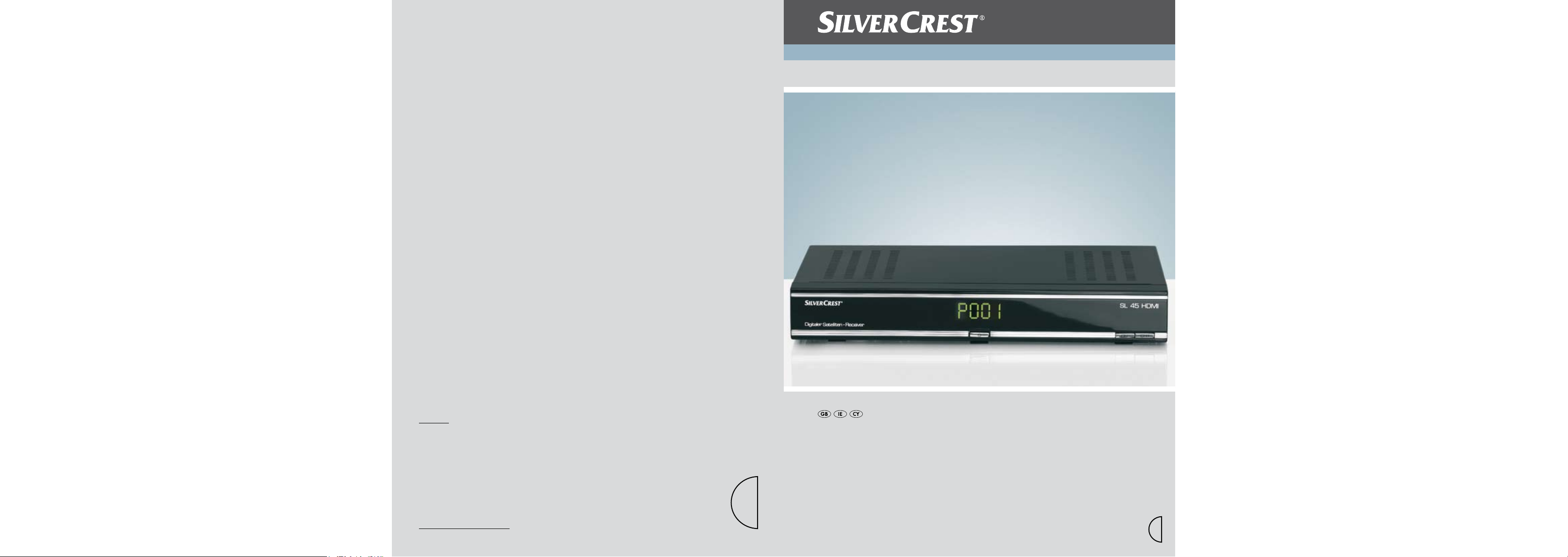
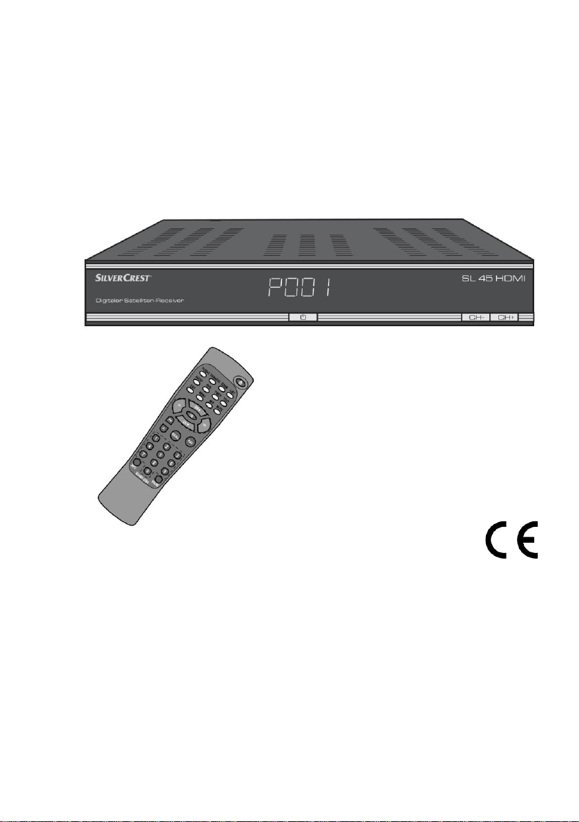
Digital Satellite Receiver
Operation and Safety Notes
6
Digital Satellite Receiver
IAN 49021
COMAG Handels AG
Zillenhardtstraße 41
D-73037 Göppingen
© by ORFGEN Marketing
Last Information Update: 04 / 2010
Ident.-No.: SL 45 HDMI042010-6
6
Please open!Please open!
Page 3
Overview of equipment
SL 45 HDMI
CH-CCH+
Digitaler Satelliten-Receiver
HDMI
100% Black+Silver
for light surfaces
Overview of equipment
GUARANTEE
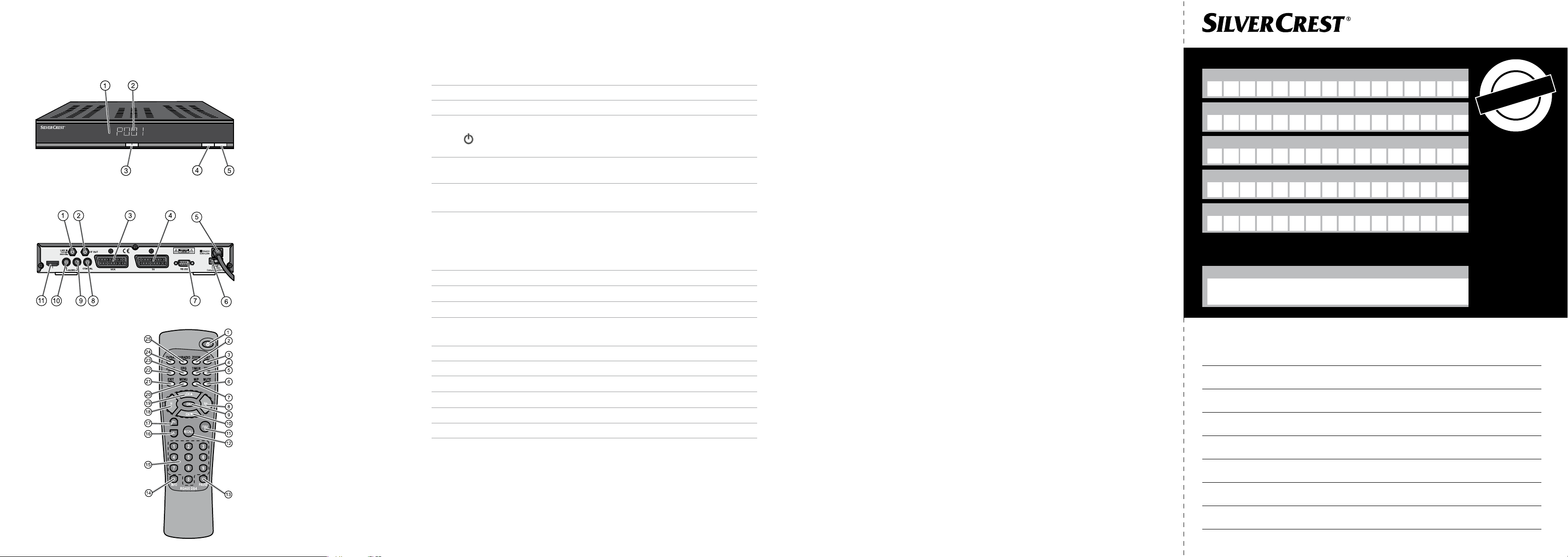
Front side of the receiver
Rear side of the receiver
Remote control
Front side of the receiver
1 – Infrared sensor for the signals of the remote control
2 LED-Display Shows the channel location in operating mode.
3 Standby key Switches on and switches to the standby mode
The default settings will be restored if you keep this
key pressed for more than 10 seconds. Caution! By
doing this, your personal settings will be deleted.
4 CH- Switches to the next lower channel location
Cursor moves down
5 CH+ Switches to the next higher channel location
Cursor moves up
Rear side of the receiver
1 LNB IN LNB connection for the antenna cable
2 IF OUT LNB connection for a second satellite receiver
3 VCR (output) SCART connection for the video set
4 TV (output) SCART connection for the TV set
5 100 – 240 V~ Mains connection
50/60 Hz, 20 W
6 ON/OFF Mains switch
7 RS 232 Serial port
8 COAXIAL Digital coaxial audio output
9 AUDIO L Stereo audio connection L(eft)
10 AUDIO R Stereo audio connection R(ight)
11 HDMI HDMI connection
Sender please use block-writing in boxes with CAPITAL LETTERS
Surname
Firstname
Street
Postcode and city
Telefon no. with areacode
Model / Type: SL 45 HDMI
Signature of buyer
PLEASE CUT THIS CARD AND ENCLOSE IT TO THE RETURNING GOOD
Faulty-Description:
t
h
n
s
o
•
m
6
3
•
•
Guarantee
•
•
f
r
o
m
Zintek Systems Ltd
Zintek House
Eurohaul Centre
Greenhills Road
Tallaght
Dublin 24
Service-Hotline:
00353 (0) 1400 8353
E-Mail:
info@zintek.tv
•
s
a
h
p
c
r
u
•
•
e
t
a
d
-
e
#
Page 4
1
Standby
Switches on and to the standby mode
2
ZOOM
Enlarges TV image
3
LIST
Invokes TV channel list
4
TIMER
Invokes timer
5
TEXT
Invokes Teletext
6
MUTE
Turns off sound
7
M/P
Multi-picture function, invokes thumbnail view
8
V+
Increases volume/cursor moves to the right
9
OK
In normal mode: invokes current channel list In a
menu: confirms menu item
10
CH
Switches to the next lower channel location/
cursor moves down
11
FAV
Invokes own favourites list
12
RECALL
Switches to previously selected channel
13
PAUSE
Stills the frame
14
INFO
Displays reception data of the current channel
(satellite-finder function)
15
0–9
Selects channel directly, numerical input
16
P–
In normal mode: changes channel group
In TV channel list: Ten-key block commutation
17
P+
In normal mode: changes channel group
In TV channel list: Ten-key block commutation
18
V–
Decreases volume/cursor moves to the left
19
CH
Switches to the next higher channel location/
cursor moves up
20
MENU
Invokes main menu
21
EXIT
Exits menu or menu item
22
AUDIO
Changes audio mode
23
EPG
Invokes Electronic Programme Guide (if offered by
the broadcasting station)
24
TV/SAT
Switches between terrestrial and satellite antenna
25
TV/RADIO
Switches between TV and radio mode
Remote control
Page 5
Digital Satellite Receiver
SL 45 HDMI
Operating manual
Modifications and errors reserved.
We do not assume any liability for printing errors.
Version 1.2 IE, 23/04/2010
Dear customer,
Having in mind an environmentally friendly behaviour we
ask you to switch off your receiver after usage by
operating the mains switch at the rear side of the device.
With this, you contribute to the protection of the
environment and save money.
Page 6

Preface
This operating manual will help you in the
appropriate
safe
favourable
usage of the digital satellite receiver, in short, the
“receiver”. We assume that the user of the receiver has
overall knowledge regarding the handling of audio and
video equipment.
Each person who
installs
connects
operates
cleans
disposes of
this receiver must be familiar with the entire content of
this operating manual. Always keep this operating
manual in the proximity of the receiver.
Style features
Specific style features have been used in different
sections of the operating manual. Thus, you can easily
differentiate whether it concerns
normal text,
enumerations
or
actions.
3
Page 7
Contents
Preface ............................................................................3
Style features .................................................................3
Contents .........................................................................4
Safety instructions.........................................................6
Basic safety instructions ...........................................6
Explanation of safety instructions .................................. 10
Appropriate use ............................................................. 10
Scope of supply ........................................................... 11
Description ................................................................... 12
Connecting the receiver .............................................. 16
LNB cable installation .................................................... 17
Connection with the HDMI cable .................................... 20
Connection with the SCART cable ................................. 22
Audio connection mit Cinch-Kabel ................................. 24
Connection of an audio-digital receiver .......................... 26
Connection and rough direction of the antenna ............. 28
Getting started ............................................................. 33
Remote control .............................................................. 33
The receiver ................................................................... 35
Operation ...................................................................... 36
Screen-inlays while switching channels ......................... 36
User interface on the TV screen .................................... 38
Menu structure ............................................................... 39
Menu navigation ............................................................ 40
Channel (symbol: TV) .................................................... 41
Installation (symbol: satellite antenna) ........................... 47
System Setup (symbol: receiver) ................................... 51
Tools (symbol: tool case) ............................................... 57
4
Page 8

Software update via satellite .......................................... 58
Keys with special functions ........................................ 59
Switch between TV and SAT ......................................... 59
Switch between TV and radio ........................................ 59
ZOOM ................................ ............................................ 59
LIST ............................................................................... 60
AUDIO ........................................................................... 60
EPG ............................................................................... 60
TEXT.............................................................................. 61
M/P ................................................................................ 61
MUTE ............................................................................. 62
FAV ................................................................................ 62
RECALL ......................................................................... 62
INFO - acoustic signal for directing the satellite
antenna .......................................................................... 63
0 - Sleep timer ............................................................... 63
PAUSE ........................................................................... 63
Uninstalling the receiver ............................................. 64
Cleaning ........................................................................ 64
Tips & tricks/trouble shooting .................................... 65
Disposal ........................................................................ 69
Specifications .............................................................. 70
Manufacturer ................................................................ 72
Guarantee ..................................................................... 73
Conformity hint ............................................................ 74
Glossary ....................................................................... 75
5
Page 9
Safety instructions
Please read the safety instructions carefully before
operating the receiver.
Please follow all warnings and instructions on the
equipment and in the operating manual.
Basic safety instructions
Electrical connection
Separate the receiver from the power source in case of
operational disruptions. Please note: The receiver will
remain live, even if it is turned off with the mains switch
on the rear side.
Do not expose the receiver to rain or any kind of
humidity to avoid risk of fire and electric shock.
Never open the casing. Otherwise, there is a risk of
electric shock.
Connect the receiver only to a professionally installed
mains socket of 100–240 V~, 50–60 Hz.
The total power consumption by the antenna
connection of the receiver “LNB IN” must not exceed
300 mA.
Pull out the mains plug from the socket if the
equipment is not in use for a longer period of time.
Only pull at the mains plug, not at the cable.
In case of storms pull out the mains plug of the
receiver from the socket.
In case of a storm, loosen the LNB cable from the
receiver.
6
Page 10

Caution!
Note regarding separation from the mains supply. The
Standby key of this device does not separate the
device completely from the mains supply. In addition,
the device consumes current in standby mode. To
If foreign bodies or fluids enter the receiver,
immediately pull out the mains plug from the socket.
Ask a qualified person to check the equipment before
operating it again. Otherwise, there is a risk of electric
shock.
Ensure that the power source (socket) is easily
accessible.
Do not bend or crimp the mains cable.
If the mains cable is damaged, the
receiver must be repaired by an expert before reusing
it. Otherwise, there is a risk of electric shock.
Never allow children to operate the receiver or to play
with the antenna unit unless supervised.
Always ask qualified personnel to carry out
maintenance jobs. Otherwise, you are putting yourself
and others at risk.
Disconnect the receiver from the power source in case
of operational disruptions.
Spare parts must be ordered directly from the
manufacturer
Modifications of the device lead to an extinction of the
manufacturer’s liability.
Remove the protection films.
7
Page 11

separate the device completely from the mains supply,
the mains plug must be pulled out of the socket.
Suitable location
Place the receiver on a stable and even base.
Avoid proximity to:
- heat sources, like e. g. heaters,
- naked flames, like e. g. candles,
- devices with strong magnetic fields, like e.g.
loudspeakers.
- Never place receptacles filled with liquid (e. g.
vases) on the receiver
Avoid direct sunlight and places with an extremely high
amount of dust.
Never cover ventilation slits. Ensure adequate
ventilation of the receiver.
Do not place any heavy objects on the receiver.
Humidity may settle in the receiver if it is brought into
hot surroundings from a cold one. In this case, wait for
about an hour before operating the equipment.
Arrange the mains and antenna cable in such a
manner that no-one steps or trips over them.
8
Page 12

Correct battery handling
Batteries may contain toxic agents. Ensure that
batteries are not within the reach of children. Children
may eat and swallow batteries.
Batteries that are getting discharged may damage the
remote control. If the receiver is not in use for a longer
period of time, remove the batteries from the remote
control.
Batteries may contain toxic agents. Therefore, dispose
of the batteries immediately in an ecologically
accepted manner according to the prevailing statutory
regulations. Never throw the batteries into normal
household waste.
Never expose the batteries to open fire or strong heat,
as otherwise there is a danger of explosion.
Replace the batteries always by batteries of the same
type.
9
Page 13
Danger!
Instructions with the word DANGER give a warning
against possible personal injuries.
Caution!
Instructions with the word CAUTION give a warning
against possible material or environmental damages.
These instructions contain special information
regarding an economic use of the receiver.
Explanation of safety instructions
The following categories of safety instructions are
included in this operating manual:
Appropriate use
The receiver is designed for receiving unencrypted digital
satellite channels (free-to-air, SDTV) for private use. It is
exclusively meant for this purpose and must only be used
for the same. This also includes paying attention to all
information contained in this operating manual, especially
in the safety instructions.
Any other usage is considered to be improper and may
lead to material damages and even personal injuries.
Moreover, it will result in the immediate loss of guarantee.
The manufacturer does not bear any liability for damages
caused due to improper use.
10
Page 14
No.
Pieces
Description
1 1 Receiver
2 1 Remote control
3 2 Batteries type AAA/1.5 V
- 1 Operating manual (not shown above)
Scope of supply
Check the scope of supply after purchase. The scope of
supply may vary according to the type of the receiver.
Please follow the information on the packaging.
11
Page 15

Description
With this receiver you are able to receive unencrypted
digital satellite channels (free-to-air) via satellite antenna.
It is not necessary to programme the receiver yet.
The most important broadcasting stations and
satellites have been pre-programmed.
The satellite antenna has to be directed towards the
desired satellite.
The receiver will scan for further new channels as soon
as you initiate the automatic scanning of broadcasting
stations for this satellite. Satellites not preset may be
added.
All receiver settings can be done easily using the user
interface (menu) on the TV monitor.
The multilingual user interface supports following
languages:
german
italian
spanish
greek
english
polish
czech
slovakian
hungarian
danish
french
12
Page 16

swedish
croatian
dutch
norwegian
finnish
slovenian
turkish
portuguese
The following satellites have been preset by the
company:
ASTRA1 19,2°E
Hotbird 13,0°E
Türksat 42°E
ASTRA2 28,2°E
Sirius2 5,0°E
Amos/Atlantic 4-5°W
HispaSat 30°W
Eutel W2 16°E
HellasSat 39°E
ASTRA 23,5°E
Other features of the equipment:
Software update via satellite ASTRA1 19.2° E or via
the RS232 connection on the rear side of the device.
Saves the channel last watched (Last Channel
Memory)
LNB control logic (sound 0/22 kHz), max. current
delivery for LNB 300 mA
13
Page 17

Symbol rate 2-35 MS/s and 950-2150 MHz input
frequency
Manual PID entry possible
3 keys at the frontage
plug & play
The power draw in standby mode is 2W only.
100–240 V~, 50/60 Hz mains connection
4500 channel storage locations
Child lock (preset password: 0000)
1 favourites list and 8 channel groups
Automatic scanning of broadcasting stations
List editor for broadcasting stations
Analogue sound output through Cinch connector
(stereo), volume adjustment possible via remote
control
AC3 coaxial output (digital audio)
2 Euro-SCART connections for TV and video set
(VCR)
HDMI-connection
Loop-through-function in standby mode for the
connection of an analogue receiver
Super fast videotext with a memory of 800 pages
Digital radio reception, background image for radio
(background display)
Additional channel information is displayed when the
channel is changed.
DiSEqC 1.0, 1.2, USALS is supported if an appropriate
antenna unit is connected
14
Page 18

A suitable channel editor is additionally available
through our hotline. Then you will be able to edit
the channel lists of the receiver using your
computer. Please read for this purpose the
information on our website www.mysilvercrest.de.
SWAP function (via Recall key)
Screen aspect ratios can be set to 4:3, 16:9, and
automatically (letterbox)
8x multi-functional timer linked with EPG, sleep timer
Electronic Programme Guide EPG (up to 14 days in
advance, channel-dependent)
SCPC/MCPC reception standard C/Ku-band satellites
Automatic selection of the TV standard with video
converter
Digital satellite finder for optical and acoustic
adjustment of the paraboloidal-type reflector
15
Page 19

The coaxial cable is not included in the scope of
supply.
Caution!
Connect the receiver to the mains supply only after you
have connected it to all equipment and the antenna
properly. Otherwise, the receiver can suffer damages.
The wire netting and the inner core of the coaxial cable
carry current during operation.
Connecting the receiver
The receiver is connected with your satellite antenna by
means of a coaxial cable. If necessary, you have to
prepare a coaxial cable before connecting the receiver.
16
Page 20
When stripping the isolation, neither the inner
core or the foil nor the wire netting must be
damaged.
Caution!
The wire netting and the foil must not touch the inner
core. The foil must enclose the inner insulation and
must not be damaged.
The wire netting must not protrude from the back
of the connector end.
LNB cable installation
(cp. installation diagram on the next page)
For the installation of the F connector on the coaxial
cable you will need a knife (ideally a wire stripper) and
side cutting pliers.
Cut 8 mm of the coaxial cable at each end up to the
inner core.
Carefully cut 10 mm of the outer insulation so that the
wire netting is exposed.
Turn the wire netting backwards and wind it over the
outer insulation in such a manner that it does not touch
the inner core.
Remove the inner insulation together with the foil
placed over it up to 2mm before reaching the wire
netting.
Rotate the F connector onto the turned-back wire
netting until the connector touches the inner insulation.
17
Page 21

Cut the inner core with a cable cutter in such a manner
that it projects maximum 1 mm from the connector.
18
Page 22
Installation diagram
Fasten the F connector of the coaxial cable onto the
“LNB IN” antenna connection of the receiver. Fasten
the other end of the coaxial cable on the LNB.
19
Page 23

The HDMI cable is not included in the scope of
supply.
Connection with the HDMI cable
Insert the HDMI cable in the HDMI socket of the
receiver.
Connect the HDMI-Kabel to the TV set. Follow the
operating manual of the TV set.
Insert the Scart cable in the Scart socket “VCR” of the
receiver if you want to connect a video set.
Connect the SCART cable with the video set. Follow
the operating manual of the video set.
Insert the Cinch connector of the Cinch cable in the
“AUDIO-R” and “AUDIO-L” sockets of the receiver if
you want to connect a stereo system.
20
Page 24
Connection diagram
21
Page 25

The Scart cable is not included in the scope of
supply.
Connection with the SCART cable
Insert the SCART cable in the SCART socket “TV” of
the receiver.
Connect the SCART cable to the TV set. Follow the
operating manual of the TV set.
Insert the Scart cable in the Scart socket “VCR” of the
receiver if you want to connect a video set.
Connect the SCART cable with the video set. Follow
the operating manual of the video set.
Insert the Cinch connector of the Cinch cable in the
“AUDIO-R” and “AUDIO-L” sockets of the receiver if
you want to connect a stereo system.
22
Page 26
Connection diagram
23
Page 27

Caution!
Never connect the Phono input of your stereo system
to the receiver; it may damage your stereo system.
Strictly follow instructions for connecting the
Cinch cable provided in the operating manual of your
stereo system.
The Cinch cable is not included in the scope of
supply.
Your TV set need not be switched on for radio
reception. The audio is given out by the
connected stereo system.
For choosing the radio station, you can use the
radio list shown on your TV set as an orientation.
Audio connection with Cinch-Cable
If you want to connect a stereo system, connect it to the
receiver with a cinch cable.
Connect the „AUDIO-R“ and „AUDIO-L“ sockets of the
receiver to the audio inouts of the stereo system.
24
Page 28

Connection diagramm
25
Page 29
Caution!
Never connect the Phono input of your stereo system
to the receiver; it may damage your stereo system.
Strictly follow instructions for connecting the
Cinch cable provided in the operating manual of your
stereo system.
Caution!
Please follow strictly the information regarding
connection in the operating manual of your audiodigital receiver.
The coaxial cable is not included in the scope of
supply.
Your TV set need not be switched on for radio
reception.
You must switch on the TV set if you want to
receive TV sound through your stereo system.
Connection of an audio-digital receiver
If you want to use 5-channel audio transmission (Dolby
digital sound/AC3), you must connect your audio-digital
receiver to the coaxial output of the receiver.
26
Page 30
Connection of the coaxial digital output
Insert the coaxial cable in the “COAXIAL” socket of the
receiver.
Connect the coaxial cable to the audio-digital receiver.
Anschluss-Schema
27
Page 31
Please follow also the instructions in the
operating manual of your satellite antenna.
Caution!
The receiver should only be connected to the power
supply after you have connected the antenna cable to
the receiver.
When searching the southern direction, the
position of the sun might help you. During
summer time, the sun is exactly in southern
position at 12 am noon and during winter at 1 pm.
Connection and rough direction of the antenna
You must connect the antenna cable to the LNB before
directing the antenna.
Screw the F plug to the LNB connection.
If you have not mounted and directed your satellite
system yet, you must first find a suitable location for
mounting the antenna. Please make sure that the
antenna is directed towards the south-east. This means,
you must have a free view in this direction when you
stand behind the antenna. Keep in mind that the antenna
must never be mounted behind a balustrade, a handrail
or other obstacles (such as trees).
28
Page 32
South South
East
You must have this view when standing behind the
antenna.
In this angle of 90° nearly all common satellite positions,
such as ASTRA1 19.2° E, Eutelsat Hotbird 13° E, and
Türksat 42° E, can be found.
Depending on which satellite you wish to receive, there
must be free sight without any obstacles in this angle.
This must especially be ensured with an installation on a
wall. Make sure that you can turn your antenna
completely without having contact with the wall of your
house before installing a corresponding wall bracket (not
necessarily included in the scope of supply).
After having made all relevant connections you can now
start with the setup of the antenna. Please check again
that the receiver is connected with the LNB of the
antenna and the receiver with your TV set. As soon as
these cable connections have been made correctly, you
can switch on the devices.
29
Page 33

First step:
Switch on your TV set. Please make sure that your TV
set has been adjusted to the receiver, i.e. in case of a
Scart connection or HDMI connection, the TV set must be
set to the correct AV channel.
Second step:
Switch on the receiver. Please ensure that the receiver
has been preset for the most common satellites and their
channels and that you just have to enter the channel
locations via the numeric keys of the remote control of
the receiver.
Example:
If you wish to receive the satellite ASTRA1 19.2° E, you
must set your receiver to channel location 1 for directing
the antenna. The same applies also for other satellites,
such as Hotbird. If you wish to direct your antenna to
Hotbird, just call a preset channel of Hotbird with your
receiver.
Third step:
Now, direct your antenna to the satellite you selected.
You have several options to do so. The easiest and most
cost-effective solution is the following way:
Stand behind the antenna and move the antenna
completely into vertical position (see picture B). Make
sure that the receiving compo-nent of the antenna is
directed towards the south (see picture A).
30
Page 34

In case of digital satellite reception, the receiver
receives the transmission signal with a time lag.
Therefore, turn the antenna very slowly and wait
at each position for some seconds until the
receiver shows the signal strength on the screen
menu.
South
Picture A Picture B
Now, turn your antenna slowly towards the east (to the
left) while observing the TV set, until the receiving
component points exactly towards the east, i.e. rotate by
90° (see picture below).
South
East
31
Page 35

Now, move your antenna in such a way that it will
become steeper by 1°. For this purpose, pull at the top of
the antenna. Now, return the antenna slowly to its initial
position towards the south. Now, turn the antenna once
again 1° steeper and move it again to the left in eastern
direction. Repeat these steps until the vertical elevation
angle crosses the horizontal azimuth angle, e.g. for
ASTRA1 at 19.2° east, and you are receiving the set
channel on your TV set.
Now, please check again if you are receiving the channel
set on the receiver and zap through the channels with the
CH and CH keys of the receiver or by using the
remote control.
As soon as you have found the desired satellite, you
should improve the direction of the antenna until you get
a clear image on all channels. You can achieve this by an
optimum adjustment of the vertical elevation angle and
the horizontal azimuth angle (see pictures A and B).
Please use also the indication of the signal strength and
signal quality by pressing the INFO key.
Finally tighten all screws thoroughly to make sure that the
direction of your antenna cannot change anymore.
32
Page 36

The strap in the battery compartment is intended
to make it easier for you to take out the batteries.
If you place the strap under the inserted batteries,
you can remove them by simply pulling it out.
Getting started
Remote control
For the remote control two batteries type AAA/1.5V are
required.
Open the battery compartment.
Insert two batteries into the battery compartment -
paying attention to the indicated polarities and push
the cover of the battery compartment carefully until it is
locked.
Replace discharging batteries on time. Otherwise, the
sending capacity of the remote control will be too low.
Always replace both batteries simultaneously and use
batteries of the same type.
33
Page 37

Caution!
Batteries may contain toxic agents that are hazardous
to health and environment. Therefore, dispose of the
batteries in any case according to the prevailing
statutory regulations. Never throw the batteries into
normal household waste.
Check the batteries of your remote control at least
once a year.
If one battery has leaked, wear protective gloves and
clean the battery compartment with a dry cloth.
The remote control transmits infrared signals to the
receiver. Please refer to the overview of the remote
control for the functioning of the keys.
Point the remote control towards the front side of the
receiver and slightly press the corresponding key
once.
34
Page 38

Caution!
Check that connections of all equipment and the
antenna are proper before connecting the receiver to
the mains.
To get into standby mode, press the red key at
top right of the remote control. The current time is
displayed on the LED. The device consumes
approx. 2W only. Currently, this is a very low
value of power consumption.
The receiver
Insert the mains plugs of the connected equipment in
the mains socket and switch it on.
Switch on the AV channel of the TV set. If the receiver
is connected via Scart and the TV set recognizes the
switching voltage emitted by the receiver, it will switch
automatically to the AV mode. If the receiver is
connected via HDMI, it depends on the TV set if it
switches automatically to the AV channel or you have
to switch by yourself to the AV channel.
Insert the mains plug of the receiver in the mains
socket. Turn on the mains switch on the rear side of
the receiver. The device is in normal mode. The LED
displays the current channel.
The receiver is supplied with preset TV channels and can
be used directly. If you want to check if new channels are
available, initiate a scan for broadcasting stations. Read
the following information further below for this purpose.
35
Page 39

Channel name
Received satellite
Current date
Current time (According to the presetting in
menu item “Time“).
Storage location
TTX
symbol
This symbol is displayed if the selected
broadcasting station offers Teletext.
EPG
symbol
This symbol is displayed if the selected
broadcasting station offers an electronic programme
guide.
Heart
symbol
The heart symbol is displayed if you have included
the channel in your favorite list.
Channelgroup
The corresponding channel-group symbol is
displayed if you have included the channel in your
Operation
Screen-inlays while switching channels
When a channel is switched, an information bar appears
on the screen for 5 seconds.
In this information bar, you will find the following
indications:
36
Page 40

symbol
channel list. An overview of the channel-group
symbols is provided on the next page.
Info
Information on the current and the following
programme “Now” – “Next”
Info
Information on the currently active channel list
Symbol
Channel group
Sport
News
Music
Movie
Shopping
Education
Leisure
Should the current programme belong to the
general channel group, no symbol will appear.
Channel-group symbols
37
Page 41

3
1
2
User interface on the TV screen
You can do individual settings of your receiver using the
menus in the user interface. For this purpose, both the
receiver and the TV set need to be switched on and
connected by a Scart or HDMI cable.
Press the “MENU” key. The main menu will be displayed.
By pressing the “EXIT“ or the “MENU“ key, you can exit
this menu again. When you exit the main menu, an
information bar appears on the screen for 5 seconds.
Navigation within the menus
Top (arrow 1): menu name
(the corresponding function symbols
are displayed at the bottom)
Middle (arrow 2): sub-menu or menu items
Below (arrow 3): The information bar shows you the
keys with which you can navigate
in the current menu.
38
Page 42

Main menu
Sub-menu
Description
Language
(symbol
corresponding
country flag)
Language
Selection of the
language in which the
OSD menu is to be
displayed.
Channel
(symbol:
TV)
Page: 41
TV Channel List
Page: 41
Radio Channel List
Page: 41
Delete All
Page: 41
Installation
(symbol: satellite
antenna)
Page: 47
Antenna Setup
Page: 47
TP Scan
Page: 48
Preset Scan
Page: 48
Auto Scan
Page: 49
System Setup
(symbol:
Receiver)
Page: 51
Audio Language
Page: 51
TV System
Page: 51
Channel setup
Page: 51
Time & Timer setting
Page: 52
OSD Setting
Page: 52
Parental Lock
Page: 52
LNB Power
Page: 53
Other
Page: 53
Tools
(symbol
tool case)
Page: 57
Default Value
Page: 57
Software-Update
Page: 57
Game
Page: 57
Information
Page: 57
Menu structure
39
Page 43

In each menu, an information bar will be
displayed containing all selection options.
Setting for Central European
summer time: GMT+02:00
winter time: GMT+01:00
Menu navigation
Use the keys “CH▲”, “CH▼”, “V+”, and “V-” to navigate
within the menus. The selected menu items are marked.
Confirm your selection with the “OK” key. By pressing the
“EXIT” key you can exit the menu again. Changes must
be confirmed additionally. Apart from this, the numerical
keys are required in further sub-menus.
Example: Setting the receiver to summer time.
Press the “MENU“ key, select "System Setup", press the
OK key, then go to "Time & Timer setting", press the
“OK” key, enter Time and press the “OK” key again. Set
“GMT+02:00“ in the item GMT Offset. Quit menu by
pressing the "EXIT“ key.
40
Page 44

Sub-menu
Description
TV channel list
1 Favorite, 2 Move, 3 Find, 4 Sort, 5 Edit,
6 Type, ▲▼Select, V- V+ Group, OK Enter,
EXIT Exit
Radio channel
list
as indicated above
Delete all
Deletion of the complete channel list.
For this purpose: Enter password (default value
0000) and confirm warning message with Yes.
Channel (symbol: TV)
1 Favorite
By pressing the 1 key you can determine your favourite
channels. Next to the corresponding channels, a heart
symbol will be displayed.
2 Move
By pressing the 2 key, the move symbol will appear
behind the marked channel. By pressing the keys CH▲
and CH▼, the channel will be moved to the desired
position. The procedure must be confirmed with OK.
3 Find
Channel scan function. By entering letters in the
appearing keyboard, a filtered channel scan is possible.
By pressing the keys CH▲, CH▼, V- and V+, you can
mark the desired letter. Confirm the marked letter by
pressing the OK key.
41
Page 45

This option is not available in the favourites list or
a channel group.
Sub-menu
Description
Edit
1 Delete, 2 Skip, 3 Lock, 4 Create, 5 Edit,
6 Del all, ▲▼Select, V- V+ Group, P+PPage, EXIT Exit
4 Sort
Sorting of the complete channel list according to the
offered options. The list must be confirmed with OK. As
long as the existing list has not been overwritten, the last
status before confirming can be restored.
5 Edit
After entering the password (default value 0000), new
selection options will appear.
1 Delete
By marking with the 1 key, selected channels can be
marked to be deleted. Please confirm your selection and
the safety message by pressing the "OK“ key.
2 Skip
By marking with the 2 key, selected channels can be
marked to be skipped. Please confirm your selection and
the safety message by pressing the "OK“ key. Then, the
selected channels are skipped when zapping. A direct
input is still possible.
42
Page 46

Option
Description
Satellite
Satellite selection (example: Astra1 19.2° East)
TP Index
Select the new transponder on the selected
satellite.
TP Frequency
Data corresponding to the selection of the
created transponder.
Symbol Rate
Data corresponding to the selection of the
created transponder.
Polarity
Data corresponding to the selection of the
created transponder.
Name
Determination of the channel name.
By pressing the OK key, an editing mask will be
displayed. By pressing the keys CH▼, CH▲,
V- and V+, the curser can be moved over the
keyboard. The selected field is marked yellow.
To select it press the OK key. The cursor jumps
to the next place.
Select the symbol group with the keys 1, 2 and
3 Lock
By marking with the 3 key, selected channels can be
marked to be locked. Please confirm your selection and
the safety message by pressing the "OK“ key. Then, the
selected channels require the entry of a password
(parental lock).
4 Create
By pressing the 4 key, the menu "Create" will be
displayed. Here, a new channel can be created.
43
Page 47

3 of the remote control.
For deleting a symbol mark the “Del“ field and
press the OK key.
Select the "OK" field as soon as the channel
name is complete and press the "OK" key to
confirm. The changed channel name will be
accepted.
If you want to exit the keyboard without any
change, press the EXIT key or mark the “Exit“
field and press the OK key.
Video PID
Video PID input with the 0-9 keys of the remote
control
Audio PID
Audio PID input with the keys 0-9 of the remote
control
PCR PID
PCR PID input with the keys 0-9 of the remote
control
Save
To exit with saving changes select save and
confirm by pressing the OK key.
Exit
To exit without saving changes select save and
confirm by pressing the OK key.
Option
Description
Name
Changes the name of the currently selected
channel.
5 Edit
By pressing the 5 key, the editing menu will be displayed.
Here, you can change the individual parameters as
desired.
44
Page 48

By pressing the OK key, an editing mask will be
displayed. By pressing the keys CH▼, CH▲,
V- and V+, the curser can be moved over the
keyboard. The selected field is marked yellow.
To select it press the OK key. The cursor jumps
to the next place.
Select the symbol group with the keys 1, 2 and
3 of the remote control.
For deleting a symbol mark the “Del“ field and
press the OK key. Select the "OK" field as soon
as the channel name is complete and press the
OK key. The changed channel name will be
accepted.
If you want to exit the keyboard without any
change, press the EXIT key or mark the “Exit“
field and press the OK key.
Video PID
Video PID input with the 0-9 keys of the remote
control
Audio PID
Audio PID input with the keys 0-9 of the remote
control
PCR PID
PCR PID input with the keys 0-9 of the remote
control
Save
To exit with saving changes select save and
confirm by pressing the OK key.
Exit
To exit without saving changes select save and
confirm by pressing the OK key.
45
Page 49

6 Del(ete) all
Via the 6 key you can mark all channels to be deleted.
Thereafter, individual channels can be deselected again
by pressing the 1 key. Please confirm your selection and
the safety message by pressing the "OK“ key.
6 Type (channel group)
Here, you can assign selected channels to determined
channel groups (Types) as desired. Please confirm
selection and safety message by pressing the "OK“ key.
You can exit the menu by pressing the "EXIT“ key.
46
Page 50

Sub-menu
Description
Antenna setup
Satellite
Satellite selection
(example: Astra1 19.2° East)
LNB Type
Select LNB type
(default value is Universal)
22K
22KHz activation,
(Note: with LNB type Universal,
activation occurs automatically)
DiSEqC
Select DiSEqC level
DiSEqC
Switch
Select DiSEqC command
Example:
Astra and Hotbird double
reception
Astra = 1 / 4
Hotbird = 2 / 4
Disable for positioner: Not
enabled
Positioner
By pressing the “OK“ key you
will go to DiSEqC positioner
menu. Please refer to the
operating manual of your
DiSEqC motor for help.
Polarity
H (Horizontal), v (vertical), H/V
(automatic operation)
Installation (symbol: satellite antenna)
47
Page 51

TP Scan
(manual
channel scan)
With this scanning function, you can scan the
preset frequencies (transponders) individually.
The transponder details can be changed
manually.
The procedure is initiated with "Scan“.
Satellite
Selection of the satellite to be
scanned
TP Index
Frequency selection
The selection options are
displayed
1 Add, 2 Delete, 3 Delete all
See following table for TP
Index.
TP
Frequency
Setting of the frequency
Symbol Rate
Setting of the symbol rate
Polarity
H = horizontal, V = vertical
Scan Mode
All = encrypted and
unencrypted channels
Free = only unencrypted
channels
Search
Start scan by pressing the OK
key. The channels and
frequency found are added.
Preset Scan
Scanning of preset frequencies (transponders).
(Normal automatic scan)
Satellite
Selection of the satellite to be
scanned
48
Page 52

Scan Mode
All = encrypted and
unencrypted channels
Free = only unencrypted
channels
Scan
Channel
Selection between TV and
radio or only TV or only radio
Search
Start scan by pressing the OK
key.
Auto Scan
(unique
function that
can be used
without any
previous
knowledge),
Here you can scan a selected satellite
(example: Astra1 19.2° East) completely to
search for new channels. For this purpose, no
special information is needed. You can choose
between free-to-air channels and all TV and
radio channels.
The procedure is initiated via "Scan“.
The signal strength and quality is displayed
permanently.
Satellite
Selection of the satellite to be
scanned
Scan Mode
All = encrypted and
unencrypted channels
Free = only unencrypted
channels
Scan
Channel
Selection between TV and
radio or only TV or only radio
Search
Start scan by pressing the OK
key. The channels found are
added.
49
Page 53

No.
Sub-menu
Description
1
Add
Create new frequency (transponder):
Menu item "TP frequency": Frequency:
set desired frequency
Menu item "Symbol rate": set
corresponding symbol rate
Menu item Polarity: set corresponding
polarisation
The new frequency (transponder) is
created after execution.
When exiting the menu confirm the safety
message by pressing the OK key. Only
after confirmation the new frequency will
be created.
For scanning the newly created
frequency, initiate the menu item "Scan".
2
Delete
Delete the selected transponder. When
confirming the safety message, the
transponder and all channels on it will be
deleted.
3
Del(ete) all
When confirming the safety message, all
transponders and all channels on them
will be deleted.
Table for the TP Index
50
Page 54

Sub-menu
Description
Audio
Language
First Audio
Preselection of audio language
(if offered by the broadcasting
station)
Second
Audio
Preselection of audio language
(if offered by the broadcasting
station)
TV System
Display
Mode
Selection of the transmission
system
Default selection: HDMI 576i
Aspect
Mode
Selection of the aspect ratio
Default selection: 4:3 Letterbox
Video
Output
CVBS
Dolby Digital
Enable (On) / disable (Off)
Channel setup
Start-up channel: Determination of the desired
TV or radio channel appearing when switching
on the receiver
Boot on
Channel
Enable (On) / disable (Off)
Mode
TV = the start-up channel is a
TV channel
Radio = the start-up channel is
a radio channel
Startup
Channel:
By pressing the OK key, a
channel list will be displayed
System Setup (symbol: receiver)
51
Page 55

for selecting the start-up
channel. Confirm the selected
channel by pressing the OK
key.
Time & Timer
Setting
Time
Optional input of time and time
zones.
See following table for time
setting.
Timer
See following table for timer
setting.
OSD Setting
Subtitle
Display
Enable / disable
OSD
Timeout
Menu display time (OSD time
lock)
OSD
Transparency
Menu transparency
Load Default
OSD Setting
OSD default value can be
restored
Parental Lock
(password
settings,
requires
password
input)
Factory password: 0000
Installation
Lock
Deactivation of password input
in the Installation menu
Channel
Lock
Deactivation of password input
for locked channels (parental
lock)
52
Page 56

New
Password
Input of a new password.
(Make sure you will remember
the new password)
Confirm
Password
Confirm new password.
LNB Power
Enabling and disabling LNB power supply. ON
is preset.
Other
Auto shutdown: 180 min / 120 min / 60 min /
disable
Preset: 180 min
Using the “Auto Shut Down” function you can
function you can set the number of minutes
after which the receiver will automatically enter
stand-by mode, if it does not receive any
commands within the set period. You can
choose between 60, 120 and 180 minutes. 2
minutes before the end of the set period a
corresponding notification will be shown briefly
to inform you. If you do not want then want the
receiver to enter stand-by mode, enter a
command using the remote control. The set
period will then start from the beginning. In
order to deactivate this function, select
“Disable”.
This function serves to protect the environment.
53
Page 57

Sub-menu
Description
GMT Usage
Enable / disable
GMT Offset
Setting of the location-dependant divergence to
Greenwich Mean Time
Date
Enabled if sub-menu “GMT Usage“ is disabled:
Date input with the keys 0-9 of the remote
control
Time
Enabled if sub-menu “GMT Usage“ is disabled:
Time input with the keys 0-9 of the remote
control
Time Display
Enabling / disabling of the time display on the
TV screen.
If GMT Usage is enabled, time in the standby
mode on the front panel of the receiver is set
automatically.
Table for time setting
54
Page 58

Sub-menu
Description
Timer Number
Selection of timer number 1-8.
Timer Mode
Type of repetition (once, daily, weekly, monthly,
yearly, off). With the setting “Off“, the timer will
be disabled.
Timer Service
Switching between programme timer (TV or
radio channels) and reminding function
(message).
Wakeup
Channel
With the timer service setting “Message“,
you have following options: Birthday,
Anniversary, and General
With the timer-service setting "TV Channel“
or "Radio Channel“,
you can select channels
Wakeup Date
Date input with the keys 0-9 of the remote
control
On Time
Time input with the keys 0-9 of the remote
control
Duration
Input duration of the event with the keys 0-9 of
the remote control.
However, the timer can also be programmed
via the EPG mode. Example:
Press the “EPG“ key. Via the 1 key you will then
get an event list. By using the keys CH▲ and
CH▼, you can select the desired event. After
Table for timer setting
55
Page 59

displaying the details by pressing the "OK" key,
the result can be taken over directly to the timer
by pressing the 2 key.
56
Page 60

Sub-menu
Description
Default Value
(requires
password
input)
Reset receiver to the default value. All changes
are cancelled.
If the receiver is reset to the default values via
the OSD menu, the language selection appears
in the main menu after completion of the
procedure. Now, switch off the receiver with the
mains switch. As soon as 5 seconds have
passed, you can switch it on again. In the
condition as supplied to the customer, the
receiver starts in normal mode.
Please note:
the default values are restored if you keep
the standby key at the front side of your
receiver pressed for more than 10 seconds.
SoftwareUpdate
(requires
password
input)
Please note:
A software update has NOTHING to do with a
scan for new TV channels. Therefore, please
initiate an automatic scan.
By means of a software update you can load
new operation software in case of need. An
update via satellite or RS232 is also possible.
Game
Here, the three games Tetris, Snake and
Othello are available.
Information
Technical details
Tools (symbol: tool case)
57
Page 61

The update has nothing to do with the storage of
new TV channels. It is rather meant to update the
system software of the receiver.
Normally, the update is not required for a troublefree operation of the receiver.
You must direct your satellite system towards the
satellite Astra1 19° East to be able to update the
software.
Updating the software may take up to an hour.
Software update via satellite
After the upgrade it is recommended to load the default
settings additionally.
ATTENTION: with this, the channel list you created will
be deleted.
58
Page 62

Keys with special functions
Switch between TV and SAT
With the “TV/SAT” key you can switch between TV and
satellite functions. (This function has to be provided by
your TV set).
Press the “TV/SAT” key until you have set the desired
function.
Switch between TV and radio
With the “TV/Radio” key you can switch between TV and
the radio function.
Now, the receiver transmits a radio channel and shows a
background image.
To return to the TV channel, press the “TV/Radio” key
of the remote control.
ZOOM
With the zoom function you can enlarge a section of the
image.
Press the “ZOOM” key. With each pressing of the
“ZOOM” key, a section of the image will be enlarged
gradually.
Select the image section with the keys CH▼, CH▲, V-
and V+.
By pressing the “EXIT” key, you can exit this mode.
59
Page 63

LIST
Press the “LIST” key once.
Here you have the option to edit the channel list as
already described earlier under menu item “Channel“.
AUDIO
With the “AUDIO” key you can select the audio track if a
broadcasting station offers multi-channel sound.
Additionally, you can enable the Dolby Digital mode here.
(For this purpose you will additionally need a Dolby
Digital system. The connection is made on the rear of the
device via the COAXIAL socket).
EPG
Electronic Programme Guide. To activate this function,
please press the “EPG“ key. The channel list will be
displayed.
With the keys CH▲ and CH▼, you can select a channel.
With the keys P+ and P-, you can jump 10 channels up or
down. On the right side, the current and the following
event will be displayed.
For getting detailed information on the current event,
press the 2 key. Press the 1 key to display the complete
event list of the selected channel. With the keys V+ and
V-, you can scroll between the days. With the keys CH▲
and CH▼, you can scroll up and down the events.
You will get detailed information on a selected event
(programme) by pressing the 1 key. A selected event of a
channel will be taken over directly to the timer by
pressing the 2 key.
60
Page 64

TEXT
Teletext is an information system displaying Teletext on
your TV set. For Teletext reception, the selected channel
must support this function. The TTX symbol appears
when channels are changed. Comparing our receiver
with others you will notice that our Teletext is extremely
fast.
Press the “TEXT“ key to start Teletext.
For switching off Teletext, press the “EXIT” or “TEXT”
key.
Using Fasttext functions
The coloured keys on the remote control are meant for
Fasttext and are enabled after invoking another Teletext
page. These functions will be available for some
channels only. You can get there directly by pressing the
small coloured keys on the remote control.
Press the desired key.
M/P
Press the “M/P“ key to go to the multi-picture mode. Now,
9 channels will appear simultaneously on your screen,
starting with the current channel.
With the keys CH▼, CH▲, V- and V+, you can move the
yellow marking bar. The marked channel is displayed in
real time. All other channels are displayed as freeze
images.
To enable the desired channel, mark it and then press
the “OK” or "EXIT” key.
61
Page 65

By pressing the “EXIT“ key, you will leave the multipicture mode. The channel you marked last will appear
as complete image on your screen.
MUTE
By pressing the “MUTE“ key, the sound will be turned off.
By pressing the “MUTE“ key again, the sound will be
turned on again.
FAV
Press the “FAV” key.
On the screen you will see the favorite list selected by
you.
Select a channel out of the favorite list by pressing the
CH▲ and CH▼ keys.
With the keys V+ and V-, you can switch between the
favorite list and the channel groups.
Press the “OK” key to select.
Press the “FAV“ key to switch between the favorite list
and the channel groups. Select with the V- and V+
keys.
To exit the favorite list or the channel group, press the
1 key.
RECALL
By pressing the “RECALL” key, you will return to the
previously selected channel.
62
Page 66

An acoustic signal will be emitted by the TV set.
The higher the signal, the better the direction of
the antenna.
INFO - acoustic signal for directing the satellite
antenna
For this purpose, press the “INFO” key. Apart from the
current reception parameters, you will get information on
the signal strength and quality. Additionally, you can
enable an acoustic signal by pressing the 1 key.
0 - Sleep timer
You can go to the sleep timer in normal mode by
pressing the 0 key.
By pressing the 0 key again, you will have following setup
options: off, 10, 30, 60, 90, 120 minutes. After this time,
the receiver will be switched off automatically.
PAUSE
For this purpose. press the “PAUSE” key. The TV image
will be ”frozen“. By pressing the "PAUSE" key again, it
will be disabled.
63
Page 67

Caution!
The receiver must not become wet. Never clean it with
a wet cloth.
Do not use any cleaning agent containing solvents like
petrol or thinners for cleaning. These agents may
damage the surface of the casing.
Uninstalling the receiver
Separate the receiver and connected equipment from
the power supply.
Loosen the LNB cable from the receiver.
Take the batteries out of the remote control, if you will
not use the receiver for a longer period of time.
Pack the receiver, the cables and the remote control in
a cardboard box.
Store the receiver and all accessories in a dry and
dust-free room.
Protect the receiver from frost.
Cleaning
Clean the casing of the receiver with a dry cloth.
Clean the display of the receiver with a slightly wet
cloth.
64
Page 68

Symptom
Possible cause and remedy
Satellite cannot
be found, or
no signal
Example: Astra1 19.2° East
1 key (default setting: “Das Erste“)
“INFO“ key (“Das Erste“, FR11837)
Signal AND quality are both at 0%
Direct vertical reflector to the south. Turn some
millimetres to the left, wait approx. 3 seconds
and repeat, until signal AND quality are
displayed. With a signal of approx. 60%, the
black background disappears and the TV
image will be displayed.
For changing the satellite please select a
current channel out of the preset channel list
and then press the INFO key.
Frontal display
dark
The mains cable is not connected.
Connect the mains cable with the power
source.
No sound or
image, but
receiver menus
are displayed
The antenna is not directed towards the
satellite.
Direct the antenna properly.
No signal (with symbol).
Check the cable connection from the LNB to
the receiver and from the receiver to the
connected equipment.
Direct the antenna.
Tips & tricks/trouble shooting
65
Page 69

Frontal display
shows channel
location.
The TV set does
not display any
image.
The system is not connected properly.
Check connection of the SCART cable or
HDMI cable.
The TV set is not in AV mode.
Switch the TV set to the respective AV input.
Poor image,
blocking error,
formation of small
blocks, sound
stops
The antenna is not directed exactly towards
the satellite.
Direct the antenna more precisely. For this
purpose, use the “Info” key of the remote
control. The signal strength will be displayed
for directing the antenna properly.
The LNB is defective. Replace the LNB.
No image, no
sound, signal
strength and
signal quality OK
The satellite antenna has been directed to a
wrong satellite.
Bad reception of:
DSF, etc.
Wireless telephone is disturbing (DECT
standard). Move your telephone to another
place.
System crash
(receiver cannot
be operated
anymore.)
Should it come to the improbable case of a
system crash, separate the receiver from the
mains supply. Connect it again after 10
seconds. With this, the problem can be solved
usually.
Please note: a software crash is not a
malfunction and no guarantee will apply. For
technical equipment (e.g. also PC, radio
network, etc.) a software crash can be solved
simply and quickly by following this procedure.
66
Page 70

The remote
control does not
work.
The batteries are exhausted.
Replace the batteries.
The remote control is not directed properly.
Aim the remote control towards the front side
of the receiver and ensure that there is no
obstacle between the remote control and the
receiver.
Channel has
received new
frequency and is
not transmitted
anymore with the
current data
Delete the corresponding channel and carry
out an automatic scan.
Exit favourites list
Press the FAV key and the 1 key.
Password
The default password is 0000.
Cannot remember
personal
password
Please contact the service hotline if you have
forgotten your personal password.
Operating manual
in additional
languages
On the website www.mysilvercrest.de this
operating manual is available for download in
additional languages.
Channel-list editor
On the website www.mysilvercrest.de a
channel-list editor is available for download.
Default value
The default settings are restored if you keep
the standby key at the front side of your
receiver pressed for more than 10 seconds.
Caution! By doing this, your personal settings
will get lost.
67
Page 71

If a problem cannot be rectified in spite of this, please
contact your specialized dealer or the manufacturer.
68
Page 72

Disposal
European disposal directive 2002/96/EC
Never throw the receiver into normal household waste.
Ask your municipal authorities or local government about
different methods for disposing of the equipment in an
eco-friendly and proper manner.
Never throw the batteries into normal household waste.
Batteries may contain toxic agents. Therefore, it is
essential to dispose of the batteries according to the
prevailing statutory regulations and the statutory return
obligation. Ask your municipal authorities or local
government about different methods of disposal in an
eco-friendly and proper manner. Hand over used
batteries to a collection centre. With this you will make a
positive contribution to pollution control.
69
Page 73

Receiver
Dimensions in mm (W×D×H)
280 × 170 × 46
Weight in grammes
Receiver 904 g
Remote control 80 g (without
batteries)
Range of input frequency
950 MHz ~ 2150 MHz
IF band width
55 MHz / 8 MHz (below 5MS/s)
LNB power supply
13/18 V, 0.30 A max.
Overload protection
LNB control
22 kHz ± 2 kHz, 0.6 V pp ± 0.2 V
DiSEqC control
Version 1.0, Version 1.2, tone
burst A/B
Symbol rate
2 ~ 35 MS/s
Input speed
Max. 15 Mbit/s
Error correction (FEC)
1/2, 2/3, 3/4, 5/6, 7/8, auto
Aspect ratio
4:3 letterbox, 4:3 PanScan, 16:9
Video resolution
720 x 576 (Pal), 720 x 480 (NTSC)
Audio mode
Left, right, stereo, AC3 digital
sound
Connection options
LNB IF input
Type F, IEC 169-24
IF OUT
Type F, IEC 169-24
TV SCART (output only)
Audio L, R, Video (CVBS)
VCR SCART (output and
input)
Video (CVBS), Audio L, R
RCA (CINCH)
Audio L, R
Specifications
70
Page 74

COAXIAL
Digital audio output
HDMI
HDMI connection
RS 232
RS 232 (Service)
Power supply
Input voltage power pack
100-240 V ~, 50/60 Hz
Power consumption
approx. 20W (operation with
Single LNB)
approx. 5W (receiver only,
operation mode)
approx. 2W (standby)
Operating temperature
0 ºC ~ +40 ºC
Storage temperature
– 40 ºC ~ + 65 ºC
71
Page 75

Manufacturer
COMAG Handels AG
Zillenhardtstraße 41
D-73037 Göppingen
Germany
Telephone: 0049 (0)7161 / 5 03 06 – 0
Telefax: 0049 (0)7161 / 5 03 06 – 11
Website: www.comag-ag.de
Dear customer,
Past experience has shown that many complaints can be
settled through a simple telephone call.
In case problems should arise with your device we kindly
ask you to contact our service hotline first. Proceeding
like this will save you time and possible irritation.
Our hotline personnel will be glad to help you and explain
the exact procedure of guarantee handling, should it
become necessary to send in your device.
Service hotline: 00353 (0)1400 8353
E-mail: info@zintek.tv
72
Page 76

Guarantee
The guarantee for the digital camping satellite system of
COMAG Handels AG is in conformity with the prevailing
statutory regulations at the time of purchasing the
product. The term of guarantee is 3 years.
Modifications of the device lead to an extinction of the
manufacturer’s guarantee obligation. A crash of the
system software is not considered a malfunction and no
guarantee will apply.
73
Page 77

Conformity hint
The manufacturer hereby declares conformity with the following guidelines and standards for this product:
Low-voltage guideline 2006/95/EC
Guideline on electromagnetic compatibility,
2004/108/EC
Ecodesign Directive 2009/125/EC, regulation
107/2009
Equipment type/model:
Digital Satellite Receiver SL 45 HDMI
Göppingen, 23/04/2010
COMAG Handels AG
74
Page 78
AC
Alternating Current
Connection for alternating current
DC
Direct Current
Connection for direct current
Cinch
connector
Coaxial connector for connecting TV set or stereo
system.
DiSEqC
Digital Satellite Equipment Control
Digital system, with which the receiver can control
different components of the external unit. It is
especially used for selecting from multiple satellite
positions (for example Astra and Eutelsat).
EPG
Electronic Programme Guide
IF connector
Coaxial connector for LNB antenna cable.
FTA
Free-to-air services
Free-of-charge services that can be received
without a special decoder.
HDMI
Connection for digital transmission of audio and
video signals.
LNB
Low Noise Block Amplifier / Converter
A device at the centre of the antenna, which
converts high-frequency incoming signals from
satellites into a low-frequency range and amplifies
them simultaneously.
Mute
Key of the remote control for turning off sound
Glossary
75
Page 79

OSD
On-screen display
Menu control displayed on the screen.
PID
Identification number of a received data stream
The PIDs ensure that a channel is received
completely.
Receiver
Receiver unit, which converts signals from the
antenna into video and audio signals.
SCART
A 21-pole connector for connecting the TV set to
the receiver.
Swap
function
Switches between current channel and channel
last watched.
Transponder
Satellite frequency. Several digital channels can be
broadcasted simultaneously on a transponder.
VCR
Abbreviation for Video Cassette Recorder.
YUV
YUV is a signal formed by one brightness (Y) and
two colour difference signals (UV). This signal is
transmitted over three individual cables.
76
 Loading...