


 Loading...
MAMMOMAT 1000/3000 Nova - Opdimar
Service
Service Instructions
ASW V3.1
|
|
|
|
© Siemens AG 2003 |
|
|
The reproduction, transmission or |
|
|
use of this document or its contents |
|
|
is not permitted without express |
|
|
written authority. Offenders will be |
|
|
liable for damages. |
All rights, |
|
including rights created by patent |
|
|
grant or registration of a utility |
|
|
model _or_ design,_are_ reserved. |
|
Register 5 |
English |
|
Print No.: SPB7-230.061.11.02.02 |
Doc. Gen. Date: |
07.03 |
Replaces: SPB7-230.061.11.01.02 |
(66 31 951) |

0 - 2 |
|
|
Revision |
|
|
|
|
Chapter |
Page |
Revision |
|
|
|
|
|
All |
All |
02 |
|
|
|
|
|
Document revision level
The document corresponds to the version/revision level effective at the time of system delivery. Revisions to hardcopy documentation are not automatically distributed.
Please contact your local Siemens office to order current revision levels.
Disclaimer
The installation and service of equipment described herein is to be performed by qualified personnel who are employed by Siemens or one of its affiliates or who are otherwise authorized by Siemens or one of its affiliates to provide such services.
Assemblers and other persons who are not employed by or otherwise directly affiliated with or authorized by Siemens or one of its affiliates are directed to contact one of the local offices of Siemens or one of its affiliates before attempting installation or service procedures.
Opdimar |
Register 5 |
SPB7-230.061.11 |
Page 2 of 6 |
Siemens AG |
Service |
|
Rev. 02 07.03 |
CS PS 24 |
Medical Solutions |
Contents |
|
|
|
|
|
|
|
|
0 - 3 |
||
|
|
|
|
|
|
|
|
|
|
Page |
|
Document revision level . . . . . . |
. . . |
. . |
. . . . . . . . . . . |
. |
. |
. . . |
. |
. |
. |
. . |
2 |
Disclaimer . . . . . . . . . . . . . |
. . . |
. . |
. . . . . . . . . . . |
. |
. |
. . . |
. |
. |
. |
. . |
2 |
1 _______Prerequisites __________________________________________________ 1 - 1
General . . . . . . . . . . . . . . . . . . . . . . . . . . . . . . . . . . . . . . . . . 1 - 1 Training of customer support engineers . . . . . . . . . . . . . . . . . . . . . . . . . 1 - 1 Documents required . . . . . . . . . . . . . . . . . . . . . . . . . . . . . . . . . . . 1 - 1 CD-ROMs required . . . . . . . . . . . . . . . . . . . . . . . . . . . . . . . . . . . 1 - 1 Meters and appliances required . . . . . . . . . . . . . . . . . . . . . . . . . . . . . 1 - 2 Tools required . . . . . . . . . . . . . . . . . . . . . . . . . . . . . . . . . . . . . . 1 - 2
2 _______Functional description __________________________________________ 2 - 1
Block diagram . . . . . . . . . . . . . . . . . . . . . . . . . . . . . . . . . . . . . . 2 - 1 Biopsy controller. . . . . . . . . . . . . . . . . . . . . . . . . . . . . . . . . . . . . 2 - 2 Biopsy unit control . . . . . . . . . . . . . . . . . . . . . . . . . . . . . . . . . . 2 - 2 RS-232 switching . . . . . . . . . . . . . . . . . . . . . . . . . . . . . . . . . . 2 - 2 CCD camera power supply . . . . . . . . . . . . . . . . . . . . . . . . . . . . . 2 - 2 LEDs . . . . . . . . . . . . . . . . . . . . . . . . . . . . . . . . . . . . . . . . . 2 - 2 Workstation . . . . . . . . . . . . . . . . . . . . . . . . . . . . . . . . . . . . . . . 2 - 3 Application software . . . . . . . . . . . . . . . . . . . . . . . . . . . . . . . . . 2 - 3 CCD camera communication . . . . . . . . . . . . . . . . . . . . . . . . . . . . 2 - 4 Control of MAMMOMAT and biopsy unit . . . . . . . . . . . . . . . . . . . . . . 2 - 4 Monitor. . . . . . . . . . . . . . . . . . . . . . . . . . . . . . . . . . . . . . . . 2 - 4 CCD camera. . . . . . . . . . . . . . . . . . . . . . . . . . . . . . . . . . . . . . . 2 - 4 Biopsy unit. . . . . . . . . . . . . . . . . . . . . . . . . . . . . . . . . . . . . . . . 2 - 4
3 _______Protective measures for CCD camera ______________________________ 3 - 1 4 _______Protective measures ____________________________________________ 4 - 1 5 _______Service mode __________________________________________________ 5 - 1
|
General . . . . . . . . . . . . . . . . . . . . . . . . . . . . . . . . . . . . . . . . . 5 - 1 |
|||
|
Advanced service . . . . . . . . . . . . . . . . . . . . . . . . . . . . . . . . . . . . 5 - 1 |
|||
|
Selection of mode . . . . . . |
. . . . . . . . . . . . . . . . . . . . . . . . . . . . . . 5 - 2 |
||
|
Calibration of the biopsy unit |
. . . . . . . . . . . . . . . . . . . . . . . . . . . . . . 5 - 3 |
||
|
Setting up needles. . . . . . . . . . . . . . . . . . . . . . . . . . . . . . . . . . . . 5 - 6 |
|||
|
Editing needle values . . . . . . . . . . . . . . . . . . . . . . . . . . . . . . . . 5 - 7 |
|||
|
Backup of temporary storage media . . . . . . . . . . . . . . . . . . . . . . . . . . 5 - 8 |
|||
|
Use of Advanced service functions . . . . . . . . . . . . . . . . . . . . . . . . . . . 5 - 9 |
|||
|
General . . . . . . . . . |
. . . . . . . . . . . . . . . . . . . . . . . . . . . . . . 5 - 9 |
||
|
Main menu . . . . . . . . . . . . . . . . . . . . . . . . . . . . . . . . . . . . . . 5 - 9 |
|||
|
Country settings . . . . . . . . . . . . . . . . . . . . . . . . . . . . . . . . . . . . 5 - 11 |
|||
|
Test of units . . . . . . . . . . . . . . . . . . . . . . . . . . . . . . . . . . . . . . 5 - 12 |
|||
|
Software upgrade . . . . . . . . . . . . . . . . . . . . . . . . . . . . . . . . . . . 5 - 13 |
|||
|
New software version . . . . . . . . . . . . . . . . . . . . . . . . . . . . . . . 5 - 14 |
|||
|
Enabling the DICOM option . . . . . . . . . . . . . . . . . . . . . . . . . . . . 5 - 15 |
|||
|
Instruction for obtaining the systems host ID and hostname . . . . . . . . . . . 5 - 15 |
|||
|
|
|
|
|
Siemens AG |
Register 5 |
SPB7-230.061.11 |
Page 3 of 6 |
Opdimar |
Medical Solutions |
Rev. 02 07.03 |
CS PS 24 |
Service |
|

0 - 4 |
|
Contents |
|
|
Page |
Network settings . . . . . . . . . . . . . . . |
. . . . . . . . |
. . . . . . . . . . .5 - 17 |
Miscellaneous. . . . . . . . . . . . . . . . . |
. . . . . . . . |
. . . . . . . . . . .5 - 18 |
Restoring data from MO disk . . . . . . . . . . . |
. . . . . . . . |
. . . . . . . . . . .5 - 21 |
CCD camera calibration and maintenance . . . |
. . . . . . . . |
. . . . . . . . . . .5 - 22 |
Grid table . . . . . . . . . . . . . . . . . . . |
. . . . . . . . |
. . . . . . . . . . .5 - 22 |
Non grid table . . . . . . . . . . . . . . . . . |
. . . . . . . . |
. . . . . . . . . . .5 - 23 |
Disk cache settings . . . . . . . . . . . . . . . . |
. . . . . . . . |
. . . . . . . . . . .5 - 24 |
Use of printer setup. . . . . . . . . . . . . . . . |
. . . . . . . . |
. . . . . . . . . . .5 - 25 |
Stand alone Opdima system . . . . . . . . . |
. . . . . . . . |
. . . . . . . . . . .5 - 25 |
Networked Opdima system . . . . . . . . . . |
. . . . . . . . |
. . . . . . . . . . .5 - 26 |
Log administration . . . . . . . . . . . . . . . . |
. . . . . . . . |
. . . . . . . . . . .5 - 28 |
Log inspection . . . . . . . . . . . . . . . . . . |
. . . . . . . . |
. . . . . . . . . . .5 - 29 |
6 ______ Removal and replacement of sub-assemblies _______________________6 - 1
General . . . . . . . . . . . . . . . . . . . . . . . . . . . . . . . . . . . . . . . . . 6 - 1 MO unit . . . . . . . . . . . . . . . . . . . . . . . . . . . . . . . . . . . . . . . . . 6 - 1 Removing the MO unit . . . . . . . . . . . . . . . . . . . . . . . . . . . . . . . 6 - 1 Installing the MO unit . . . . . . . . . . . . . . . . . . . . . . . . . . . . . . . . 6 - 2 Tests and Adjustments . . . . . . . . . . . . . . . . . . . . . . . . . . . . . . . 6 - 3 Biopsy controller . . . . . . . . . . . . . . . . . . . . . . . . . . . . . . . . . . . . 6 - 4 Removal of biopsy controller . . . . . . . . . . . . . . . . . . . . . . . . . . . . 6 - 4 Removal of biopsy controller cover . . . . . . . . . . . . . . . . . . . . . . . . . 6 - 5 Replacement of components in the biopsy controller. . . . . . . . . . . . . . . . 6 - 5 Cables . . . . . . . . . . . . . . . . . . . . . . . . . . . . . . . . . . . . . . . . . 6 - 7 Biopsy unit . . . . . . . . . . . . . . . . . . . . . . . . . . . . . . . . . . . . . . . 6 - 8 Workstation . . . . . . . . . . . . . . . . . . . . . . . . . . . . . . . . . . . . . . . 6 - 8 Connectors . . . . . . . . . . . . . . . . . . . . . . . . . . . . . . . . . . . . . 6 - 8 CCD camera . . . . . . . . . . . . . . . . . . . . . . . . . . . . . . . . . . . . . .6 - 10 Reinstallation of software. . . . . . . . . . . . . . . . . . . . . . . . . . . . . . . .6 - 11
Installation of Operating Solaris 8 Installation CD-ROM for,
(Mat. No. 66 33 049) . . . . . . . . . . . . . . . . . . . . . . . . . . . . . . . .6 - 11 Installation of Opdima Software Installation CD-ROM (Mat. No. 66 33 700) . . . .6 - 12 Restore hostname and data . . . . . . . . . . . . . . . . . . . . . . . . . . . .6 - 12 Final procedures . . . . . . . . . . . . . . . . . . . . . . . . . . . . . . . . . .6 - 14
7 ______ Messages _____________________________________________________7 - 1
Workstation . . . . . . . . . . . . . . . . . . . . . . . . . . . . . . . . . . . . . . . 7 - 1 Control panel . . . . . . . . . . . . . . . . . . . . . . . . . . . . . . . . . . . . . . 7 - 3
8 ______ Fault isolation chart_____________________________________________8 - 1
Fault isolation chart. . . . . . . . . . . . . . . . . . . . . . . . . . . . . . . . . . . 8 - 1 Explanations . . . . . . . . . . . . . . . . . . . . . . . . . . . . . . . . . . . . . . 8 - 2
9 ______ Troubleshooting guide __________________________________________9 - 1
General . . . . . . . . . . . . . . . . . . . . . . . . . . . . . . . . . . . . . . . . . 9 - 1 Biopsy unit . . . . . . . . . . . . . . . . . . . . . . . . . . . . . . . . . . . . . . . 9 - 2 Biopsy unit not responding . . . . . . . . . . . . . . . . . . . . . . . . . . . . . 9 - 2
Opdimar |
Register 5 |
SPB7-230.061.11 |
Page 4 of 6 |
Siemens AG |
Service |
|
Rev. 02 07.03 |
CS PS 24 |
Medical Solutions |

Contents |
0 - 5 |
|
|
|
Page |
Problem with calibration . . . . . . . . . . . . . . . . . . . . . . . . . . . . . |
. . 9 - 2 |
|
Initialization of BC nvram on the D200 board . . . . . . . . . . . . . . . . . . |
. . 9 - 2 |
|
Camera . . . . . . . . . . . . . . . . . . . . . . . . . . . . . . . . . . . . . . . |
. . 9 - 4 |
|
Camera not responding . . . . . . . . . . . . . . . . . . . . . . . . . . . . . |
. . 9 - 4 |
|
Cannot use camera . . . . . . . . . . . . . . . . . . . . . . . . . . . . . . . |
. . 9 - 4 |
|
Workstation . . . . . . . . . . . . . . . . . . . . . . . . . . . . . . . . . . . . . |
. . 9 - 5 |
|
If “Bogus file system” appears . . . . . . . . . . . . . . . . . . . . . . . . . . |
. . 9 - 5 |
|
Problem with date in database mode . . . . . . . . . . . . . . . . . . . . . . |
. . 9 - 5 |
|
Opdima user interface does not appear at log in . . . . . . . . . . . . . . . . |
. . 9 - 5 |
|
No images displayed on monitor . . . . . . . . . . . . . . . . . . . . . . . . |
. . 9 - 5 |
|
Problems with the centering or size of the displayed image on the monitor. . . |
. . 9 - 6 |
|
Problems with the DICOM license . . . . . . . . . . . . . . . . . . . . . . . . |
. . 9 - 6 |
|
Tests . . . . . . . . . . . . . . . . . . . . . . . . . . . . . . . . . . . . . . . |
. . 9 - 7 |
|
Image Quality . . . . . . . . . . . . . . . . . . . . . . . . . . . . . . . . . . . . |
. . 9 - 8 |
|
Problems during calibration . . . . . . . . . . . . . . . . . . . . . . . . . . . |
. . 9 - 8 |
|
Quadrant difference on patient images . . . . . . . . . . . . . . . . . . . . . |
. . 9 - 8 |
|
Quadrant missing . . . . . . . . . . . . . . . . . . . . . . . . . . . . . . . . |
. . 9 - 8 |
|
White line/dot . . . . . . . . . . . . . . . . . . . . . . . . . . . . . . . . . . |
. . 9 - 8 |
|
MAMMOMAT . . . . . . . . . . . . . . . . . . . . . . . . . . . . . . . . . . . . |
. . 9 - 9 |
|
Cannot use MAMMOMAT . . . . . . . . . . . . . . . . . . . . . . . . . . . . |
. . 9 - 9 |
|
Network problem . . . . . . . . . . . . . . . . . . . . . . . . . . . . . . . . . . |
. |
9 - 10 |
Printer . . . . . . . . . . . . . . . . . . . . . . . . . . . . . . . . . . . . . . . . |
. |
9 - 11 |
Printer connected directly to Opdima . . . . . . . . . . . . . . . . . . . . . . |
. |
9 - 11 |
Printer connected to network . . . . . . . . . . . . . . . . . . . . . . . . . . |
. |
9 - 11 |
MO unit . . . . . . . . . . . . . . . . . . . . . . . . . . . . . . . . . . . . . . . |
. |
9 - 12 |
All problems with MO disk . . . . . . . . . . . . . . . . . . . . . . . . . . . . |
. |
9 - 12 |
If the message “Failed to store on MO disk” appears . . . . . . . . . . . . . . |
. |
9 - 12 |
If the message “Cannot read disk Prepare disk?” appears . . . . . . . . . . . |
. 9 - 12 |
|
Cannot communicate with MO unit . . . . . . . . . . . . . . . . . . . . . . . |
. |
9 - 12 |
10 ______Measures after service _________________________________________ 10 - 1 |
|
Verifying the calibration of the biopsy unit . . . . . . . . . . . . . . . . . . . . . . . 10 - 1 |
|
Check of Opdima AEC . . . . . . . . . . . . . . . . . . . . . . . . . . . . . . . . 10 - 2 |
|
Procedure . . . . . . . . . . . . . . . . . . . . . . . . . . . . . . . . . . . . . 10 - 2 |
|
Performance Criteria. . . . . . . . . . . . . . . . . . . . . . . . . . . . . . . . 10 - 3 |
|
Check of resolution . . . . . . . . . . . . . . . . . . . . . . . . . . . . . . . . . . 10 |
- 4 |
Procedure . . . . . . . . . . . . . . . . . . . . . . . . . . . . . . . . . . . . . 10 |
- 4 |
Performance Criteria. . . . . . . . . . . . . . . . . . . . . . . . . . . . . . . . 10 |
- 4 |
Protective earth measurement . . . . . . . . . . . . . . . . . . . . . . . . . . . . 10 |
- 5 |
Biopsy unit . . . . . . . . . . . . . . . . . . . . . . . . . . . . . . . . . . . . . 10 - 5 Biopsy controller . . . . . . . . . . . . . . . . . . . . . . . . . . . . . . . . . . 10 - 5 CCD camera . . . . . . . . . . . . . . . . . . . . . . . . . . . . . . . . . . . . 10 - 6 Biopsy controller cable duct . . . . . . . . . . . . . . . . . . . . . . . . . . . . 10 - 6
11 ______Changes to previous version ____________________________________ 11 - 1 12 ______Appendix 1 __________________________________________________ A1 - 1
Siemens AG |
Register 5 |
SPB7-230.061.11 |
Page 5 of 6 |
Opdimar |
Medical Solutions |
|
Rev. 02 07.03 |
CS PS 24 |
Service |

0 - 6 |
Contents |
Database log file . . . . . . . . . . . . . . . . . . . . . . . . . . . . . . . . . . . A1 - 1
13 _____ Appendix 2 __________________________________________________ A2 - 1
Customer specific data . . . . . . . . . . . . . . . . . . . . . . . . . . . . . . . . |
A2 |
- 1 |
Test protocol repetitiveness. . . . . . . . . . . . . . . . . . . . . . . . . . . . . . |
A2 |
- 1 |
Biopsy calculations . . . . . . . . . . . . . . . . . . . . . . . . . . . . . . . . |
A2 |
- 1 |
Test protocol CCD camera calibration . . . . . . . . . . . . . . . . . . . . . . . . |
A2 - 2 |
|
Test protocol image quality . . . . . . . . . . . . . . . . . . . . . . . . . . . . . . |
A2 |
- 3 |
AEC function . . . . . . . . . . . . . . . . . . . . . . . . . . . . . . . . . . . |
A2 |
- 3 |
Resolution . . . . . . . . . . . . . . . . . . . . . . . . . . . . . . . . . . . . |
A2 |
- 5 |
Test protocol protective earth measurement . . . . . . . . . . . . . . . . . . . . . |
A2 - 6 |
|
Biopsy unit . . . . . . . . . . . . . . . . . . . . . . . . . . . . . . . . . . . . |
A2 |
- 6 |
Biopsy controller . . . . . . . . . . . . . . . . . . . . . . . . . . . . . . . . . |
A2 |
- 6 |
CCD camera . . . . . . . . . . . . . . . . . . . . . . . . . . . . . . . . . . . |
A2 |
- 6 |
Biopsy controller cable duct . . . . . . . . . . . . . . . . . . . . . . . . . . . |
A2 - 6 |
|
14 _____ Appendix 3 ___________________________________________________14 - 1
Customer specific data . . . . . . . . . . . . . . . . . . . . . . . . . . . . . . . . .14 - 1 Test protocol repetitiveness. . . . . . . . . . . . . . . . . . . . . . . . . . . . . . .14 - 1 Biopsy calculations . . . . . . . . . . . . . . . . . . . . . . . . . . . . . . . . .14 - 1 Test protocol CCD camera calibration . . . . . . . . . . . . . . . . . . . . . . . . .14 - 2 Test protocol image quality . . . . . . . . . . . . . . . . . . . . . . . . . . . . . . .14 - 3 AEC function . . . . . . . . . . . . . . . . . . . . . . . . . . . . . . . . . . . .14 - 3
Resolution . . . . . . . . . . . . . . . . |
. . . . . . . . . . . . . . . . . . . . .14 - 5 |
|
Test protocol protective earth measurement . |
. . . . . . . . . . . . . . . . . . . . .14 - 6 |
|
Biopsy unit . . . . . . . . . . . . . . . . |
. . . . . . . . . . . . . . . . . . . . .14 |
- 6 |
Biopsy controller . . . . . . . . . . . . . |
. . . . . . . . . . . . . . . . . . . . .14 |
- 6 |
CCD camera . . . . . . . . . . . . . . . |
. . . . . . . . . . . . . . . . . . . . .14 |
- 6 |
Biopsy controller cable duct . . . . . . . |
. . . . . . . . . . . . . . . . . . . . .14 - 6 |
|
Opdimar |
Register 5 |
SPB7-230.061.11 |
Page 6 of 6 |
Siemens AG |
Service |
|
Rev. 02 07.03 |
CS PS 24 |
Medical Solutions |

Prerequisites |
1 - 1 |
General
Valid for Opdimar system ASW 3.1 on SUN workstation, part No. 66 33 718.
This document is valid for a Sun Blade 150 (SUN workstation with serial No.W1600).
Training of customer support engineers
Due to the technology used in this equipment, setup, service and maintenance may only be carried out by a customer support engineer who has attended a training workshop or has participated in at least one installation.
Documents required
•Supplement to the Instructions for Use MAMMOMAT 3000 - Opdimar (included in the Opdimardelivery)
•MAMMOMAT 1000/3000 Nova - OpdimarMaintenance Instructions (included in the Opdimardelivery)
•MAMMOMAT 3000 - OpdimarWiring Diagram (included in the Opdimardelivery)
•MAMMOMAT 3000 - OpdimarInstallation and Start-Up Instructions (included in the Opdimardelivery)
•MAMMOMAT 1000/3000 Nova Wiring Diagram
CD-ROMs required
•Sun Blade 150 Hardware Documentation (included in the Opdimardelivery) Files included on the CD-ROM;
Sun Blade 150 Getting Started Guide,
Sun Blade 150 Service Manual with Sun Blade 150 ShowMe How Animations and Setting Up the Sun Blade 150 System.
•OPDIMArSolaris 8 Installation CD v1.0, part No. 66 33 049 (included in the Opdimardelivery)
•OPDIMArInstallation CD, version 3.1, part No. 66 33 700 (included in the Opdimardelivery)
Siemens AG |
Register 5 |
SPB7-230.061.11 |
Page 1 of 2 |
Opdimar |
Medical Solutions |
|
Rev. 02 07.03 |
CS PS 24 |
Service |

1 - 2 |
Prerequisites |
Meters and appliances required
•Protective ground wire tester (44 15 899 RV090)
•Stereo calibration phantom (included in the Opdimardelivery) (part No. 64 30 701)
•AEC calibration plexiglass, four plates measuring 150 mm x 150 mm x 19 mm and one plate measuring 150 mm x 150 mm x 9,7 mm, part No. 65 61 232 and 65 61 224 respectively
•(On the territory of the US generally calibration phantom of 4.5 cm PMMA is known, it can be used wherever possible instead of the above plexiglas.)
•Resolution phantom with at least 10 line pairs per mm. Recommended is the bar pattern phantom (part no. 07-555, or part no. 18-216) from Nuclear Associates, URL http:// www.nucl.com
•PC with a CD drive running Windows 95 or later by using Netscape NavigatorTM, version 5.0 or later, or Internet Explorer, version 5.0 or later or Acrobat©ReaderTM 5.0 or later (to be able to read Sun Blade 150 Service manuals).
Tools required
•Standard service tools
•PROM extractor for PLCC 32
Opdimar |
Register 5 |
SPB7-230.061.11 |
Page 2 of 2 |
Siemens AG |
Service |
|
Rev. 02 07.03 |
CS PS 24 |
Medical Solutions |

Functional description |
2 - 1 |
Block diagram
The block diagram below shows the function of the Opdimar system.
M3000 printer / |
|
M3000 stand |
|
230V AC |
||
service PC |
RS-232 |
|
RS-232 |
|||
|
|
|
|
|||
|
|
|
|
|
|
|
|
|
|
|
|
|
|
|
|
Mains |
|
|
|
|
|
|
|
|
|
|
|
|
|
|
|
|
X206 |
cable |
|
|
|
|
|
|
|
|
|
|
|
|
|
|
|
Biopsy |
|
|
|
|
|
|
|
|
|
|
|
|
|
|
|
|
|
controller |
|
|
|
|
|
|
|
|
|
|
Workstation |
|
|
|
|
|
|
|
|
|
|
|
|
|
|
|
|
|
|
|
|
|
|
|
|
D200 Biopsy |
|
|
|
|
|
|
|
|
|
|
|
|
|
|
|
|
X205 |
control board |
AC |
|
|
|
|
|
|
|
|
|
|
|
|
|
|
|
|
|
|
|
|
|
|
|
|
|
||
|
|
|
|
|
|
|
|
|
DC |
|
|
|
|
|
|
|
|
|
|
|
2 x RS-232 |
|
A |
|
|
|
COM |
|
|
|
|
|
|
|
|
|
|
|
|
|
|
|
|
|
|
|
|
|
|
|
|
||
|
|
|
|
|
exp. sync. |
X204 |
DTR |
|
AC |
|
|
|
|
|
|
|
|
|
|
|
|
|
B |
|
|
|
7V |
|
DC |
|
|
|
|
|
|
|
|
|
|
|
|
|
|
|
|
|
|
|
|
|
|
||
|
|
|
|
|
biopsy data |
|
|
|
|
|
|
|
|
|
|
|
|
|
|
|
|
|
|
|
|
|
7V |
20V |
30V |
|
|
|
|
|
|
|
|
|
|
|
|
|
POW_ON |
|
|
AC |
|
M3000 |
|
||||
|
|
|
|
|
|
|
|
|
|
|
|
|
|
|
|
||
|
|
|
D101 Camera |
|
|
|
|
|
|
|
|
|
DC |
|
Biopsy unit |
||
System |
|
BUS |
interface board |
|
|
|
|
|
|
|
|
|
|||||
|
|
|
|
|
POW_ON |
|
|
|
|
|
|
|
|
||||
monitor |
|
|
|
|
|
|
|
|
|
|
5V |
|
|
|
|
||
|
|
PCI |
|
|
|
|
|
|
|
|
|
|
|
|
|
|
|
|
|
|
|
X101 |
X203 |
|
|
|
|
|
|
X207 |
X885 |
|
|
|
|
|
|
|
|
|
|
|
CPU |
|
|
|
|
|
|
||||
Graphics |
|
|
BUS |
|
|
|
|
|
|
|
|
|
|
|
|
|
|
CPU |
|
422 |
12-bit image |
|
|
|
|
|
|
|
|
|
|
|
|
||
acc. |
|
|
|
|
|
|
|
|
|
|
|
|
|
||||
|
|
data |
|
|
|
|
|
|
|
|
|
|
|
|
|||
|
|
|
PCI |
RS- |
X101 |
X203 |
|
|
|
|
|
|
X207 |
X885 |
X |
Y |
Z |
|
|
|
|
|
|
|
|
|
|
|
|
|
|||||
RAM |
|
|
|
|
control data |
|
|
|
|
|
|
ADC |
|
|
|
|
|
|
|
|
|
|
|
|
|
|
|
|
|
|
|
|
|
|
|
Incoming mains: 100, 120; |
|
|
|
|
|
X202 |
X202 |
X202 |
|
|
X201 |
|
|
|
|
|
|
|
|
|
|
|
|
|
|
|
|
|
|
|
|
|
|
||
|
200 - 240V AC |
|
|
|
|
|
|
|
|
|
|
|
|
|
|
|
|
|
|
|
|
|
|
|
X111 |
X110,X111 |
X111 |
|
|
X112 |
CCD camera |
|
|
|
|
Printer |
D110 CCD |
camera board |
|
(option) |
DC |
|
|
|
DC |
|
5V_COM |
CCD
control  ADC logic
DC
DC
5V C_CL CCD_R A_CL SRC_CL
CCD sandwich
= Galvanic separation
Fig. 1 Block diagram
OPD00614
Siemens AG |
Register 5 |
SPB7-230.061.11 |
Page 1 of 4 |
Opdimar |
Medical Solutions |
|
Rev. 02 07.03 |
CS PS 24 |
Service |

2 - 2 |
Functional description |
Biopsy controller
The biopsy controller has three main functions:
•Biopsy unit control
•Switching of RS-232 from MAMMOMAT to either MAMMOMAT printer/service PC or workstation
•CCD camera power supply
Biopsy unit control
The biopsy functions are controlled by the micro controller. In the biopsy unit there are three potentiometers indicating the current needle position.
The values from the potentiometers are A/D converted and sent to the micro controller. To check the converted values from the A/D converter, the potentiometer values are converted in parallel by the micro controller.
RS-232 switching
To enable RS-232 communication between MAMMOMAT and either MAMMOMAT printer/ service PC or workstation, a relay is used. The relay is controlled by the workstation.
CCD camera power supply
The biopsy controller converts the mains AC voltage to DC voltages. The DC voltages are used by the CCD camera.
LEDs
On the biopsy controller printed circuit board, D200, there are a number of LEDs with the following meaning:
•Indication of RAM error
•Indication of PROM error
•Indication of analog/digital converter
•Indication of NVM error
•Indication of TxD error
•Selection of RS-232 communication to MAMMOMAT printer/service PC or workstation (SELECT_WS)
•Supply voltages (e.g. 5V_COM, 30V_CC)
For more information on LEDs, see MAMMOMAT 1000/3000/3000 Nova - Opdimar Wiring Diagram.
Opdimar |
Register 5 |
SPB7-230.061.11 |
Page 2 of 4 |
Siemens AG |
Service |
|
Rev. 02 07.03 |
CS PS 24 |
Medical Solutions |
Functional description |
2 - 3 |
Workstation
The workstation includes the following parts:
•Main unit, including temporary storage media i.e. hard disk
•Monitor
•Keyboard and mouse
•Internal CD drive
•External MO unit i.e. magneto-optical drive, used for the permanent storage media and backup
The workstation is used for:
•Running application software
•Communication with the CCD camera
•Control of MAMMOMAT and biopsy unit
Application software
The application software run by the workstation is the main communication interface with the user and units of the Opdimar system.
Start-up and login
Mode selection
Stereo examination |
|
Spot examination |
|
Database |
|
Service mode |
mode |
|
mode |
|
mode |
|
|
|
|
|
|
|||
|
|
|
|
|
|
|
Data storage |
|
Help (n.a.) |
|
Error handling |
|
|
|
|
|
OPD00595
Fig. 2 Application software logic flow
Siemens AG |
Register 5 |
SPB7-230.061.11 |
Page 3 of 4 |
Opdimar |
Medical Solutions |
|
Rev. 02 07.03 |
CS PS 24 |
Service |

2 - 4 |
Functional description |
CCD camera communication
The camera interface in the workstation main unit sends commands to the CCD camera from the workstation and receives the image from the camera. The interface adapts the workstation data bus to RS-422.
The camera interface also supplies the CCD camera opto couplers with power.
Control of MAMMOMAT and biopsy unit
The workstation controls the MAMMOMAT via RS-232 communication.
Biopsy calculations are performed by the workstation and target coordinates are sent to the biopsy unit.
Monitor
If the settings of the monitor has changed, set values as specified in the Monitor Installation Instruction.
CCD camera
The CCD camera consists of a printed circuit board, CCD sandwich and RS-422 interface. When the x-ray beams reach the CCD sandwich, electric energy proportional to the x-ray energy is produced. The produced electrical current is A/D converted to digital information and sent to the workstation RAM via an RS-422 interface.
Biopsy unit
The biopsy unit is used for performing biopsy examinations.
The biopsy unit consists of a needle positioning device which is firmly attached to an 18 cm x 24 cm object table with a cut-out contour that is superimposed on the CCD. External stereo diaphragm, needle support and compression plate are also included in the biopsy unit. The biopsy unit can easily be attached to the swivel arm of the MAMMOMAT.
There are three displays on the biopsy unit front. The displays show spatial deviation of needle tip from the suspect point in x-, y- and z-axis calculated by the workstation.
Three potentiometers monitors the actual position of the needle tip.
Opdimar |
Register 5 |
SPB7-230.061.11 |
Page 4 of 4 |
Siemens AG |
Service |
|
Rev. 02 07.03 |
CS PS 24 |
Medical Solutions |

Protective measures for CCD camera |
3 - 1 |
CAUTION
The CCD camera has to be handled with extreme care, it is very sensitive to mechanical shocks and temperature. When not connected do not touch the pins in the camera contacts. Shock and temperature sensors are integrated in the camera.
CAUTION
The CCD camera is sensitive to mechanical shock and shall always be stored in the attaché case, delivered with the system, when disconnected from the biopsy controller.
The camera shall be used within 10230i C.
The camera shall be transported or stored within 0240i C.
Siemens AG |
Register 5 |
SPB7-230.061.11 |
Page 1 of 2 |
Opdimar |
Medical Solutions |
|
Rev. 02 07.03 |
CS PS 24 |
Service |

3 - 2 |
Protective measures for CCD camera |
This page intentionally left blank.
Opdimar |
Register 5 |
SPB7-230.061.11 |
Page 2 of 2 |
Siemens AG |
Service |
|
Rev. 02 07.03 |
CS PS 24 |
Medical Solutions |

Protective measures |
4 - 1 |
It is very important that any intervention in the equipment shall start with disconnecting it from the power supply with the main circuit breaker. To prevent accidental triggering of high voltage and radiation, set the switch S2 (SS) on board D702 to OFF (lower position, no triggering of the SS relay).
CAUTION
When switching off the workstation use the power off procedure described in the Supplement to the Instructions for Use MAMMOMAT 3000 - Opdimar.
Switching off the workstation before the software has been closed down may cause damage to the files on the hard disc.

 WARNING If the system is only switched off at the control panel or with S2/ D711 in the MAMMOMAT generator, line voltage will still be present at the generator line connection, line filter Z1, Z2, transformer T1, transformer T10 and board D711 (see MAMMOMAT 1000/3000 Nova Wiring Diagram). The Opdimar is switched off separately.


 WARNING

CAUTION
After shut-down of the system, there may still be about 380 V DC present on the intermediate circuit of the MAMMOMAT generator. This will be indicated by LED V24 on board D710. The voltage will drop to less than 30 V within about 3 minutes, the LED goes out at about 30 V.
Observe the currently valid guidelines for handling electronics endangered by electrostatic discharge.
Use ESD-equipment, ground prior to making contact and place the components on a conductive surface.
The boards contain electrostatic highly sensitive components requiring particular care in their handling.
Risk of damaging components.
Siemens AG |
Register 5 |
SPB7-230.061.11 |
Page 1 of 2 |
Opdimar |
Medical Solutions |
|
Rev. 02 07.03 |
CS PS 24 |
Service |

4 - 2 |
Protective measures |
This page intentionally left blank.
Opdimar |
Register 5 |
SPB7-230.061.11 |
Page 2 of 2 |
Siemens AG |
Service |
|
Rev. 02 07.03 |
CS PS 24 |
Medical Solutions |

Service mode |
5 - 1 |
General
There are three different user levels in the Opdimar software.
•Regular user
•Administration user
•Service user
Administration users use the Service mode to perform the following tasks:
•Calibration of the biopsy unit
•Setting up needles
•User administration
•Network setup, DICOM nodes
•Backup functions
Advanced service
Service users can additionally access advanced service functions. To get access you have to log in with the user name “service”. The password is obtained from Siemens Head Quarter Support Center.
The following advanced service functions are included:
•Country settings
•Unit tests
•Software upgrade
•Restore disk
•Camera calibration/maintenance
•Disk cache
•Printer setup
•Log administration
•View log
NOTICE |
|
The Opdimar external diaphragm must be used for tests and cali- |
|
|
brations involving radiation. |
|
|
|
|
|
|
Siemens AG |
Register 5 |
SPB7-230.061.11 |
Page 1 of 30 |
Opdimar |
Medical Solutions |
|
Rev. 02 07.03 |
CS PS 24 |
Service |
5 - 2 |
Service mode |
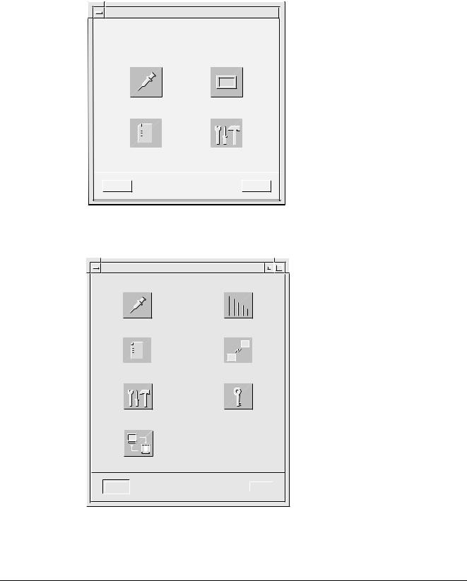
Selection of mode
After a successful login, the mode selection dialog is displayed.
1.Press the Service button. Press Logout to cancel.
Mode Selection
Press a button to enter a user mode.
Stereo |
Spot |
|||||||||||
|
|
|
|
|
|
|
|
|
|
|
|
|
|
|
|
|
|
|
|
|
|
|
|
|
|
|
|
|
|
|
|
|
|
|
|
|
|
|
|
|
|
|
|
|
|
|
|
|
|
|
|
Database |
Service |
|
|
Logout |
Help |
OPD00063
Fig. 1 Mode selection dialog
2.Select desired service function from the service dialog.
Service
Biopsy Calibration |
Needle Setup |
||||||||||||||
|
|
|
|
|
|
|
|
|
|
|
|
|
|
|
|
|
|
|
|
|
|
|
|
|
|
|
|
|
|
|
|
|
|
|
|
|
|
|
|
|
|
|
|
|
|
|
|
|
|
|
|
|
|
|
|
|
|
|
|
|
|
|
|
|
|
|
|
|
|
|
|
|
|
|
|
|
|
|
|
|
|
|
|
|
|
|
|
|
|
|
|
|
|
|
|
|
|
|
|
|
|
|
|
|
|
|
|
|
|
|
|
|
|
|
|
|
|
|
|
|
|
|
|
|
|
|
|
|
|
|
|
|
|
|
|
|
|
|
|
|
|
|
|
User Administration |
Network Setup |
Advanced Service |
Change Password |
Backup
Close |
|
Help |
|
|
|
OPD00433
Fig. 2 Service dialog
Opdimar |
Register 5 |
SPB7-230.061.11 |
Page 2 of 30 |
Siemens AG |
Service |
|
Rev. 02 07.03 |
CS PS 24 |
Medical Solutions |
Service mode |
5 - 3 |
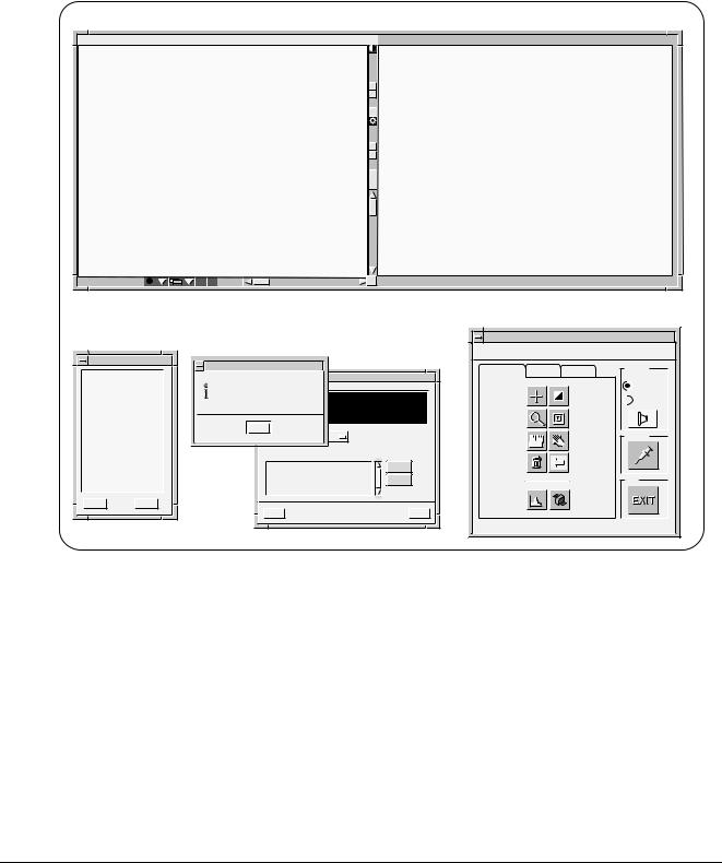
Calibration of the biopsy unit
Calibration of the biopsy unit is carried out by using a stereo calibration phantom with targets at fixed positions. By releasing two stereo pair exposures with a fine needle adjusted to different targets, the system is automatically calibrated. Follow the instructions given on the screen during the calibration procedure.
1.Press the Biopsy Calibration button in the service dialog. The following is shown on the screen:
Pixel |
x 138 |
y 152 |
value 1139 |
|
|
Gray scale |
center 1000 |
width 400 |
123-45-6789 |
|
i |
Z |
Z |
1.00x |
|
|
|
|
|
|
|
|
|
|
|
Control |
|
03/26/97 |
|
|
|
Control |
Windows |
|
Help |
|
|
|
|
|
|
|
|
|
|
|
|
Message |
|
|
|
Image Tools |
Filters |
Layout |
Acquire |
|
|
|
|
|
|
|
||||
|
1) Place and compress the stereo |
|
Targets |
|
|
|
|
||
|
|
|
|
|
|
|
Single |
||
|
calibration phantom and insert |
|
|
|
|
|
|
||
|
a fine needle of suitable length. |
|
|
|
Pointer |
|
Invert |
|
|
|
2) Move the needle holder to the first |
|
|
|
|
Double |
|||
|
calibration position. 3) Remove the |
|
|
|
|
|
|
||
|
needle. 4) Acquire a stereo pair of images.Display a stereo pair! |
|
|
|
|
||||
|
|
|
|
|
Magnify |
|
Zoom |
|
|
|
Help |
|
|
|
|
|
|
|
|
|
Default Needle |
Core 100 |
[mm] |
Ruler |
|
Pan |
Targets |
||
|
|
|
|
|
|
2 |
|
||
|
|
|
|
|
|
|
|
|
|
|
Num. |
X |
Y |
Z |
[mm] |
Delete |
|
Restore |
|
|
|
|
|
|
Delete |
|
|
||
|
|
|
|
|
|
|
|
|
|
|
|
|
|
|
Transmit |
|
|
|
Exit |
Help |
>> |
|
|
|
Histogram |
|
Screen Dump |
|
|
|
|
|
|
|
|
|
|
||
|
Close |
|
|
|
Help |
|
|
|
|
|
|
|
|
|
|
|
|
|
OPD00569 |
Fig. 3 Dialogs during calibration
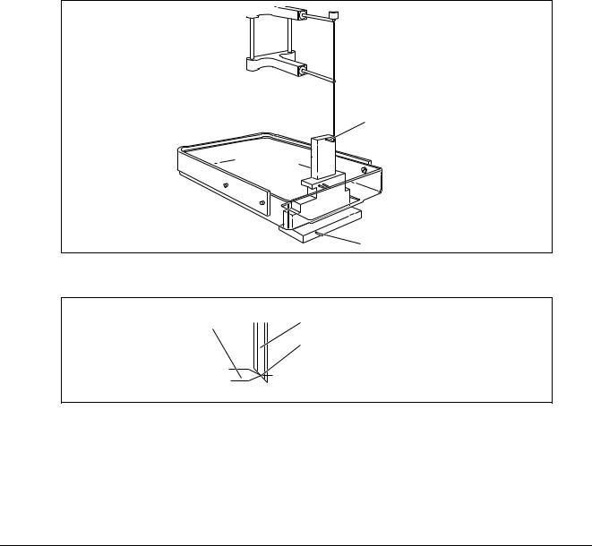
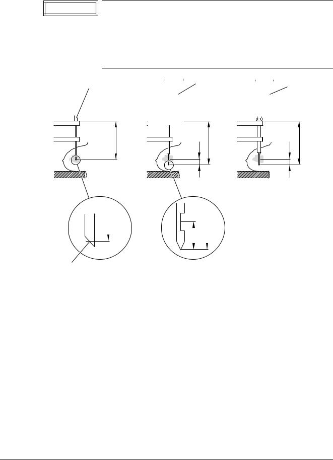
2.Place the stereo calibration phantom on the biopsy table and compress.
With the targets facing the patient side, the phantom fits in the opening of the stereo compression plate, see Fig. 4. Target 2 shall be positioned 25228 mm in negative x-axis direction and 12 mm from the object table side.
Siemens AG |
Register 5 |
SPB7-230.061.11 |
Page 3 of 30 |
Opdimar |
Medical Solutions |
|
Rev. 02 07.03 |
CS PS 24 |
Service |
5 - 4 |
Service mode |
3.Select a fine needle to be used and measure the length.
Measuring the needle length is described on Page 5 - 7.
NOTICE |
|
We recommend to use a needle that measures 90 mm, this will |
|
|
make it possible to avoid having to change needle while calibrat- |
|
|
|
|
|
ing. |
|
|
|
4.Choose Other in the Needle option menu and enter the selected needle length (minimum 90 mm).
5.Insert needle guides corresponding with the needle diameter.
6.Insert the fine needle into the needle guides.
7.Move the needle to Target 1 of the stereo calibration phantom, see Fig. 4, by using the adjustment knobs. Position the needle according to Fig. 5.
NOTICE |
|
Make sure the needle is moved to Target 1. |
|
|
|
Target 1
Target 2
Fig. 4 Stereo calibration phantom
OPD00512
Target |
Fine needle |
|
Needle channel center |
OPD00175
Fig. 5 Position of needle
8.Remove the needle.
9.Acquire and release a stereo pair of images.
Set the exposure parameters to 25 kV and 28 mAs in manual mode.
Opdimar |
Register 5 |
SPB7-230.061.11 |
Page 4 of 30 |
Siemens AG |
Service |
|
Rev. 02 07.03 |
CS PS 24 |
Medical Solutions |
Service mode |
5 - 5 |
10.Check the reference marks and adjust if necessary, mark Target 1 and press Transmit.
NOTICE |
|
When performing the biopsy calibration set the magnification to |
|
|
0.7 and change Contrast/brightness in order to find all targets in |
|
|
|
|
|
the phantom. Be sure to mark the target at which the needle tip |
|
|
was positioned. |
|
|
|
11.Insert the fine needle into the needle support of the biopsy unit.
12.Move the needle to Target 2 of the stereo calibration phantom by using the adjustment knobs.
13.Remove the needle.
14.Acquire and release a stereo pair of images.
Set the exposure parameters to 25 kV and 28 mAs in manual mode.
15.Check the reference marks and adjust if necessary, mark Target 2 and press Transmit.
When the calibration is successfully calibrated, the following message is displayed:
Message
The biopsy unit has now been calibrated. Press EXIT!
OK |
|
Help |
|
|
|
OPD00176
Fig. 6 Information message
16.Perform a final check according to Verifying the calibration of the biopsy unit on Page 10 - 1 to make sure that the biopsy unit works properly.
Siemens AG |
Register 5 |
SPB7-230.061.11 |
Page 5 of 30 |
Opdimar |
Medical Solutions |
|
Rev. 02 07.03 |
CS PS 24 |
Service |
5 - 6 |
Service mode |
Setting up needles
1.Press the Needle Setup button in the service dialog.
|
|
|
|
|
|
|
|
|
|
|
|
|
|
|
|
|
|
|
|
Needle Setup |
|
||
|
|
|
|
|
|
|
|
|
|||
|
|
|
|
|
Type |
L1 (mm) |
L2 (mm) |
|
|||
|
|
|
|
|
|
|
|
|
|
|
|
|
|
|
|
|
Fine |
90.5 |
- |
|
|
|
|
|
|
|
|
|
Core |
110.0 |
5 |
|
|
|
|
Add...
Edit...
Delete
Close |
Help |
OPD00087
Fig. 7 Setting up needles dialog
2.Press Add... .
You can only add needles which match the needle guides with the fixed diameters: 0.7, 0.9, 1.2, 1.65, or 2.1 mm.
|
|
|
|
|
|
|
|
|
|
|
|
|
|
|
|
|
|
|
|
|
|
|
|
|
|
Needles |
|
|
|
|
|
|
|
||
|
|
|
|
|
|
|
|
|
|
|
|
|
|||||
|
|
|
|
|
Enter needle values. |
|
|
|
|
|
|
|
|||||
|
|
|
|
|
|
|
|
|
|
|
|
|
|
|
|
|
|
|
|
|
|
|
Type |
|
|
|
Core |
|
|
|
|
|
|
|
|
|
|
|
|
|
|
|
|
|
|
|
|
|
|
|
|||
|
|
|
|
|
L1 |
|
|
|
|
|
|
|
|
|
|
|
|
|
|
|
|
|
|
|
|
|
|
|
|
(mm) |
|
|
|||
|
|
|
|
|
|
|
|
|
|
|
|
|
|
||||
|
|
|
|
|
L2 |
|
|
|
|
|
|
|
(mm) |
|
|
||
|
|
|
|
|
|
|
|
|
|
|
|
|
|
||||
|
|
|
|
|
|
|
|
|
|
|
|
|
|
|
|
|
|
|
|
|
|
|
|
|
|
|
|
|
|
|
|
|
|
|
|
|
|
|
|
|
|
|
|
|
|
|
|
|
|
|
|
|
|
|
|
|
|
|
OK |
|
|
Cancel |
|
|
|
|
Help |
|
|
|
|
|
|
|
|
|
|
|
|
|
|
|
|
|
|
|
|
|
OPD00088 |
|
|
|
|
|
|
|
|
|
|
|
|
|
|
|
|
|
|
|
|
|
|
|
|
|
|
|
|
|
|
|
|
|
|
|
|
Fig. 8 Needle values dialog
3.Select needle type (fine or core) from the option menu and enter needle length in the text field.
L1 shall be 30 to 175 mm when selecting fine needle, L2 is not applicable for fine needle. When selecting core, L1 shall be set to <170 mm.
Opdimar |
Register 5 |
SPB7-230.061.11 |
Page 6 of 30 |
Siemens AG |
Service |
|
Rev. 02 07.03 |
CS PS 24 |
Medical Solutions |
Service mode |
5 - 7 |
CAUTION
Ensure by measuring the length of the specified needle or core gun with needle that the right values are entered.
If the stroke length of the core gun is changed, a new needle has to be selected from the Targets dialog. The core needle length L1 shall be measured with the core needle in outer position and mounted in the core gun.
Fine needle |
|
|
Core gun |
|
Core gun |
|
|
|
|
||||
|
|
|
|
|
|
with coax |
|
|
|
|
|
|
|
|
|
|
|
|
|
|
|
|
|
|
|
|
|
L1 |
L2 |
L1 |
L2 |
L1 |
|
|
|
|
|
L1 |
|
L2 |
L1 |
|
|
|
|
|
|
|||
|
|
|
|
|
|
|||
|
|
|
|
|
|
|
||
|
|
|
|
|
|
|
|
OPD00089 |
|
|
|
|
|
|
|
|
|
Needle channel center |
|
|
||||||
|
|
|||||||
|
|
|
||||||
Fig. 9 Measuring of needle length |
|
|
|
|||||
|
|
|
|
|
|
|
|
|
NOTICE |
|
When using core gun, the system safety margin to avoid hitting |
||||||
|
|
|
|
the biopsy table is 5 mm. |
|
|
|
|
|
|
|
|
|
|
|
||
|
|
|
|
|
|
|
|
|
Editing needle values
1.Select a needle from the needle setup dialog.
2.Press Edit... .
Siemens AG |
Register 5 |
SPB7-230.061.11 |
Page 7 of 30 |
Opdimar |
Medical Solutions |
|
Rev. 02 07.03 |
CS PS 24 |
Service |
5 - 8 |
Service mode |
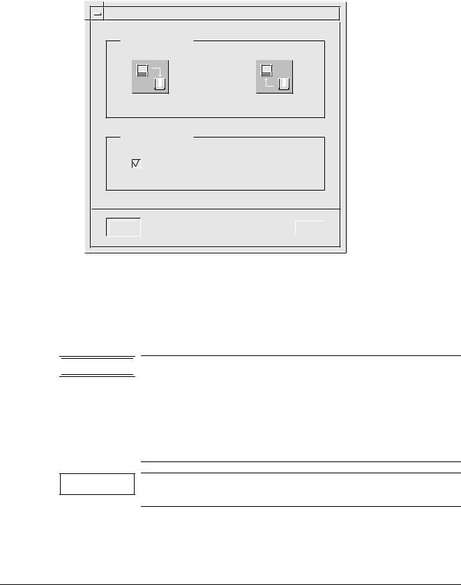
Backup of temporary storage media
As a service user it is possible to make a complete backup of all folders existing on the temporary storage media (the hard disk).
1.Press the Backup button in the service dialog.
|
Backup |
Backup / restore |
|
Backup to MO |
Restore from MO |
Setup for backup
Backup enabled
OK |
|
Help |
|
|
|
OPD00326
Fig. 10 Backup dialog
2.In the setup for backup section disable the backup.
3.Press the Backup to MO button.
4.Follow the instruction given in the message dialogs.
5.Enable the backup in the backup dialog.


 WARNING

NOTICE
Backup of temporary storage media cannot replace the regular use of backup described in Using the Backup function in Supplement to the Instructions for Use MAMMOMAT 3000 - Opdimar.
Backup of temporary storage media only saves the content present on the hard disk at the actual moment. Images may have been erased by the disk cache system (see Page 5 - 24) or software reinstallation.
This backup might take a long time and require several MO disks since all folders on hard disk will be copied to backup MO.
Opdimar |
Register 5 |
SPB7-230.061.11 |
Page 8 of 30 |
Siemens AG |
Service |
|
Rev. 02 07.03 |
CS PS 24 |
Medical Solutions |

Service mode |
5 - 9 |
Use of Advanced service functions
General
To get access to the advanced service menu you have to log in with the user name “service”. The password is obtained from Siemens Uptime Service Center (or from Headquarter Support Center).
The advanced service is carried out by using a number of text dialogs. Selection of an item in a dialog can be done in three different ways:
•Use the up/down arrows of the keyboard to step through the fields (underlined)
•Use the space bar to step through the fields
•Type the corresponding number or letter of the item
Press Enter to execute.
Main menu
The main menu is used to access all the advanced service functions.
1.Press the Advanced service button in the service dialog.
2.Select a function from the menu.
Advanced Service
SERVICES
1.Country Settings
2.Unit Tests
3.Software Upgrade
4.Restore Disk
5.Camera Calibration/Maintenance
6.Disk Cache
7.Printer Setup
8.Log Administration
9.View Log
Close
Help
Select: Close
OPD00409 Fig. 11 Advanced service dialog
|
Country Settings |
Function for selection of country of installation (your country). |
|
|
|
|
|
|
|
|
Unit Tests |
Function for performing tests of subassemblies. |
|
|
|
|
|
|
|
|
Software Upgrade |
Function for performing upgrade of software and for |
|
|
|
|
modifications of software. |
|
|
|
|
|
|
|
|
Restore Disk |
Function for restoring data from MO disk. |
|
|
|
|
|
||
|
Camera Calibration/ |
Function for performing installation and maintenance of CCD camera. |
||
|
Maintenance |
|
|
|
|
|
|
|
|
|
|
|
|
|
Siemens AG |
Register 5 |
SPB7-230.061.11 |
Page 9 of 30 |
Opdimar |
Medical Solutions |
Rev. 02 07.03 |
CS PS 24 |
Service |
|

5 - 10 |
|
Service mode |
|
|
|
|
Disk Cache |
Function for disk cache settings. |
|
|
|
|
Printer Setup |
Function for setup of printer. |
|
|
|
|
Log Administration |
Function for log settings. |
|
|
|
|
View Log |
Function for inspection of logs. |
|
|
|
|
Close |
Function for leaving the advanced service mode. |
|
|
|
Opdimar |
Register 5 |
SPB7-230.061.11 |
Page 10 of 30 |
Siemens AG |
Service |
|
Rev. 02 07.03 |
CS PS 24 |
Medical Solutions |

Service mode |
5 - 11 |
Country settings
National parameters are set in the country settings dialog. On delivery it contains default settings.
Advanced Service
COUNTRY SETTINGS
Language: English
Time Zone: MET
Time Settings: Year: 2000 Month: 10 Day: 24 Hour: 09 Minute: 21
Id Pattern: 111-11-1111
Date Pattern: m/d/y
Service Center: Undefined
Institution Name: Undefined
Department Name: Undefined
Action: Close Close/Help/Apply
OPD00513
Fig. 12 Country settings dialog
Available Languages |
Shows the languages currently available by the system. |
|
|
Language |
Selection of language in the dialogs. Select with space bar. If language |
|
is changed, log out and log in to make the change take effect. |
|
|
Time Zone |
A selection of the time zone used by the system. Select with space bar. |
|
For faster selection, type the first letter of the desired time zone name. |
|
|
Time Settings |
Value of system clock. If changed, Apply will reboot. |
|
NOTICE! The database is updated every time an examination is |
|
performed or when an image is loaded from a MO disk. The sys- |
|
tem clock cannot be set to a point earlier than the last update. |
|
|
ID Pattern |
Selection of ID-number structure. Type pattern with the keyboard: “1” |
|
for digit, “a” for letter, “?” for both digits and letters and an arbitrary char- |
|
acter for punctuation mark. For example: 111-11-1111. |
|
|
Date Pattern |
Selection of date structure. Type pattern with the keyboard: “y” for year, |
|
“m” for month, “d” for day and an arbitrary character for punctuation |
|
mark. |
|
For example: m/d/y or y-m-d (do not type mm/dd/yy or yy-mm-dd). |
|
|
Service Center |
Type the appropriate service center. |
|
|
Institution Name |
Type the appropriate name for the institution. |
|
|
Department Name |
Type the appropriate name for the department. |
|
|
1.Select Country Settings in the advanced service dialog.
2.Set the values for Language, Time Zone, ID Pattern, Date Pattern, Service Center, Institution Name and Department Name in each respective fields.
3.Select Apply and press Enter to execute the changes.
Siemens AG |
Register 5 |
SPB7-230.061.11 |
Page 11 of 30 |
Opdimar |
Medical Solutions |
|
Rev. 02 07.03 |
CS PS 24 |
Service |

5 - 12 |
Service mode |
Test of units
Advanced Service
UNIT TESTS |
|
|
Test |
Unit |
Status |
Yes |
Mammomat |
OK |
Yes |
Camera |
OK |
Yes |
Biopsy Controller |
OK |
Yes |
Modem |
N/A |
Yes |
MO-Disk |
N/A |
Yes |
Database |
OK |
Action: Run Close/Help/Run
OPD00171
Fig. 13 Unit tests dialog
NOTICE |
|
Before performing unit tests, the biopsy unit needs to be |
|
|
mounted to the MAMMOMAT. Otherwise the biopsy controller test |
|
|
|
|
|
will fail. |
|
|
|
1.Select Unit Tests in the advanced service dialog.
2.Select Yes or No to select/deselect the parts to be included in the test.
3.Select Run and press Enter.
Each unit that passes the test will be indicated with an OK message. If it does not pass, a Failed message will appear. Units that have not been tested are indicated with an Untested message.
The units are tested according to the following:
•MAMMOMAT - test if there is a connection and if the power is on
•CCD camera - test if there is a connection and if the power is on
•Biopsy controller - test if there is a connection and if the power is on
•Database - reading and writing in the database
Opdimar |
Register 5 |
SPB7-230.061.11 |
Page 12 of 30 |
Siemens AG |
Service |
|
Rev. 02 07.03 |
CS PS 24 |
Medical Solutions |

Service mode |
5 - 13 |
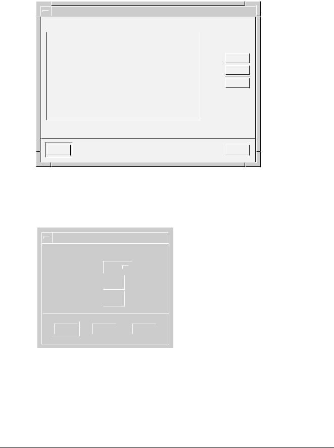
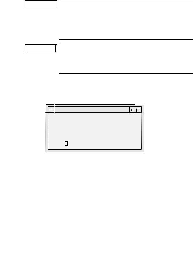
Software upgrade
The software upgrade dialog is used to upgrade the current software version with a new version from CD-ROM and to do modifications of the software.
Advanced Service
SOFTWARE UPGRADE
1.New software version
2.DICOM option
3.Network settings
4.Restore hostname
5.Update eeprom
6.Miscellaneous
Close
Help
Select: Close
OPD00514
Fig. 14 Software upgrade dialog
New software version |
Upgrade with new version from CD-ROM. |
|
|
DICOM option |
Enabling the DICOM option. |
|
NOTICE! A license key is necessary to install DICOM. |
|
|
Network settings |
Function for defining the network settings for the Opdimar sys- |
|
tem. |
|
|
Restore hostname |
The hostname of the original workstation can be restored to a |
|
new workstation. |
|
Restore hostname from most recently used local/backup MO disk. |
|
|
Update eeprom |
Not applicable. |
|
|
Miscellaneous |
Database and MO disk utilities. |
|
|
Siemens AG |
Register 5 |
SPB7-230.061.11 |
Page 13 of 30 |
Opdimar |
Medical Solutions |
|
Rev. 02 07.03 |
CS PS 24 |
Service |
5 - 14 |
Service mode |
New software version
NOTICE
CAUTION
This menu will be used when installing the next version of software.
However it is not applicable when changing from ASW 2.1 to 3.1 because of the change of the Solaris version. If the change from ASW 2.1 to 3.1 shall be done use the present instrucions in the modification instructions when installing the new software.
Make sure that all examinations are stored on the
MO disk before upgrading. The examinations are stored when exiting an examination or database session, see Storing data on MO disk in Supplement to the Instructions for Use MAMMOMAT 3000 - Opdimar.
1.Select Advanced service in the Service mode.
2.Insert the CD-ROM for the new ASW software version.
3.Select Software upgrade and New software version.
Advanced Service
NEW SOFTWARE VERSION
Current Release: opdima.3.0_6633064 CD-ROM Release: opdima.3.1_6633700
Action: Close |
Close/Help/Install |
|
|
|
|
OPD00614
Fig. 15 New software version, advanced service dialog
4.Select Install.
Opdimar |
Register 5 |
SPB7-230.061.11 |
Page 14 of 30 |
Siemens AG |
Service |
|
Rev. 02 07.03 |
CS PS 24 |
Medical Solutions |
Loading...