

Siemens 8MR6440-5EG30, 8MR6440-5EG40 Installation, Operation And Maintenance Manual
S
g
Installation, operation and maintenance manual
Montage-Betriebs und Wartungsanleitung
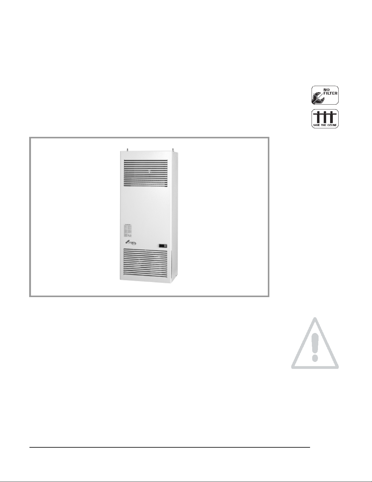
Air conditioner for electric enclosure
Schaltschrank-Kühl
erät
8MR6440-5EG30
8MR6440-5EG40
A T T E N T I O N !
Read carefully and completely before installation. Keep the manual until unit decommissioning.
Lesen Sie das vorliegende Handbuch in allen seinen Teilen aufmerksam durch, bevor das Gerät installiert wird. Das
Handbuch muss bis zum Abbau des Geräts aufbewahrt werden.
Warnhinweis: Montage und Installation von elektrischen Betriebsmitteln dürfen nur durch Elektrofachkräfte erfolgen.
Warning: Assembling and installation of electrical equipment may only happen by electro specialists.
A5E03773198A Version 01 Nov.11
F.48.0
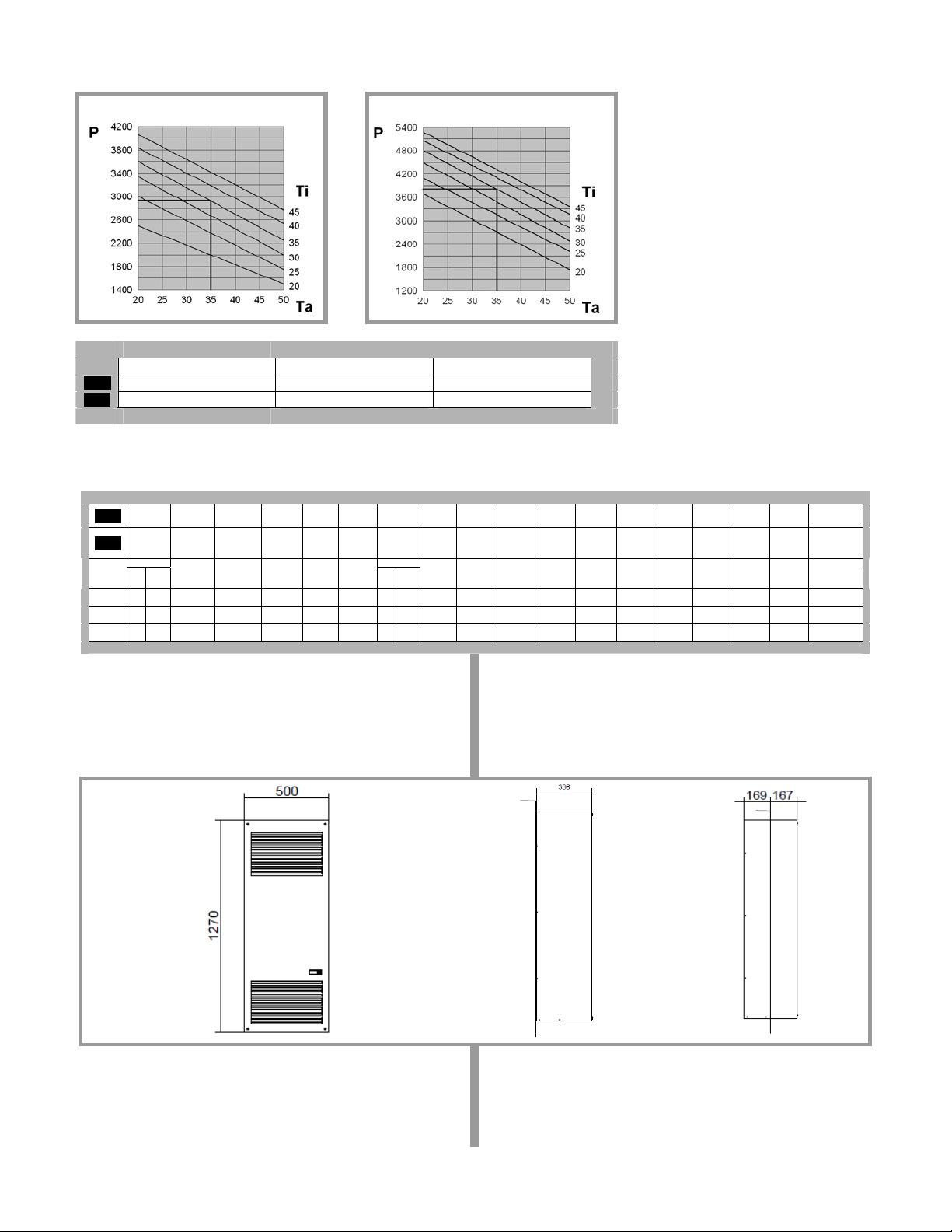
Performances / Leistungen
8MR6440-5EG30
8MR6440-5EG40
Useful cooling output Ambient temperature Enclosure internal temperature
ENG
Nutzkühlleistung Umgebungstemperatur Schaltschrank-Innentemperatur
DEU
P (W) Ta (°C) Ti (°C)
F. 49.1
Technical data / Technische Daten
Useful
Supply
Dimensions
ENG
DEU
8MR6440-
5EG30
8MR6440-
5EG40
F. 50.1
cooling
voltage
output
Nutzkühlleis-
Versorgungstung
spannung
EN814 EN814
A35
A35
W W V ~ Hz mm A A A W W - kg bar °C - °C - - Db(A) kg -
2900 2250 400 3~ 50-60 500x1270x336 2,6 14 6 1220 1440 100% 0,84 25 20-46 Thermostat 20-5 0 IP54 IP34 70 84 CE
3850 2870 400 3~ 50-60 500x1270x336 3,6 18 8 1780 2050 100% 1,14 25 20-46 Thermostat 20-5 0 IP54 IP34 70 85 CE
A35
A50
(W xHxD)
Abmessungen
(BxHxT)
Max current Starting
Höchststrom Anlauf-
current
strom
Pre-fuse T Electric
capacity
Vorsiche-
Nennleistung Einschalt-
rungT
A35
A35
Duty cycle Refrigerant Max
Kältemittel zul. Be-
dauer
R134a
A35
A50
Dimensions / Abmessungen
8MR6440-5EG30
8MR6440-5EG40
pressure
triebsüberdruck
Enclosure
temperature
range
Schaltschranktemperaturbereich
Temperatur e
control
Temperatur regelung
Ambient
temperature
range
Umgebungstemperatur- bereich
Protection
internal
circuit
Schutzart
Innenkreislauf
Protection
Noise level Weight Conformity
external
circuit
Schutzart
GeräuschAußen-
pegel
kreislauf
Gewicht Konformität
External
Außenmontage
Semi-recessed
Teileinbau
2
F.52.1
F.22.1 F.25.1
F.55.1 F.53.1
F.59.1 F.33.0 F.54.1 F.36.0
3
ENG
3
5
1. Cooling unit application.
The cooling units described in this manual are
designed and built to cool the air inside
switchboards in order to protect components
sensitive to thermal shock and, at the same
time, providing an IP54 protection level against
the infiltration of contaminating and strong substances.
2. Updates.
The manufacturer reserves the right to update
its product and relative manuals based on technical progress without prior notice. Please note
that at the time of sale, this manual and relative
product cannot be considered inadequate only
because they are not subject to abovementioned updates.
3. Technical features.
(Figures F.48.0 and F.49.1)
4. Supply.
Inside the packaging you will find:
cooling unit
1
installation, operating and maintenance
1
manual
test certificate
1
drilling template
1
1
M8 nuts
8
2
8.4x24 mm flat washers
8
M8x30 mm dowels
8
4
10x5 mm self-adhesive sealing strip
1
piece of flexible hose for discharging
1
condensate 12x2x100 mm
M8 eyebolts
2
5. Prior to assembly.
• During transport and storage the cooling
• Upon receipt, check the packaging has not
• Ambient air temperature, where the enclo-
• Make sure switchboard protection level is
• Check that the external environment does
• Check that the flows of air leaving and en-
• The supply voltage available must corre-
• The cooling unit must be installed in the
• The cooling unit must be installed with the
…
1 4
(figure F. 52.1)
(figure F. 59.1)
unit must be kept in the position clearly indicated on the packaging (figure F.1.0),
and must not be exposed to temperatures
higher than 70°C.
been damaged during shipping.
sure is to be installed, must be no higher
than 50°C and should never exceed the
cooling unit’s maximum operating temperature which is specified on its rating
plate. The unit must be positioned far away
from heat sources and flows of hot air.
IP54 or higher. Should this not be the case
excessive condensation could form. Consequently seal well all areas where cables
pass and all other openings in the enclosure.
not contain excessive concentrations of
contaminating solids and/or strong chemicals.
tering the cooling unit are not obstructed
by walls or objects that are too close. For
this purpose, in the case of the external air
flow, verify the minimum distances (figure
F.47.1), while in the case of the internal air
flow, make sure there are no obstructions
caused by the switchboard components.
spond to the features given on the cooling
unit’s rating plate.
position indicated. Maximum permitted deviation from the vertical is 2°.
enclosure air suction hole in the highest
possible point.
• If the cooling unit has to be installed on a
door, make sure the door can take the
weight.
• Before making the holes and slits on the
enclosure make sure the fixing elements
and couplings will not interfere with the
equipment inside the enclosure itself.
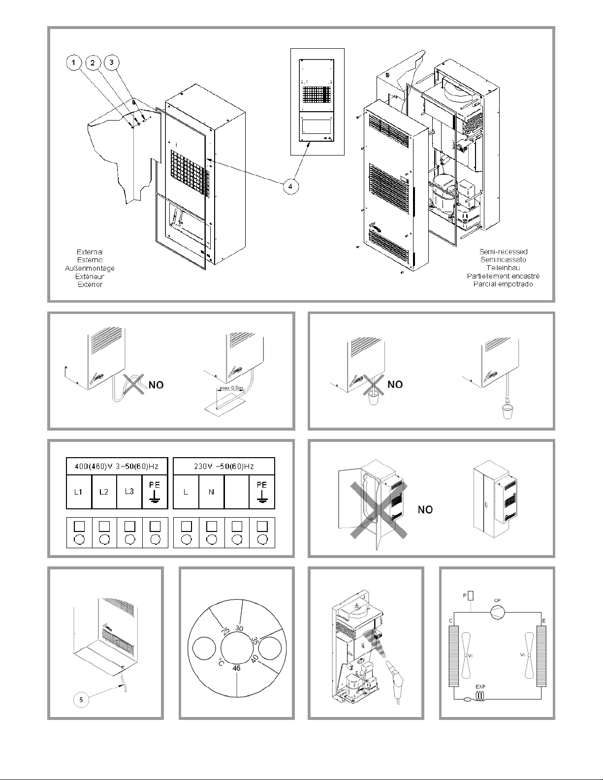
6. Assembly.
Disconnect power before starting any work inside the switchboard. The cooling unit can be
applied externally to, or semi-recessed (figure
F.50.1) on the electric enclosure as preferred
without the need for any additional accessories
(just those you will find inside the standard kit
supplied with the unit). Depending on the installation type chosen, drill the holes and make
the necessary cuts on the switchboard (figure
F.51.1) using the drilling template supplied with
the unit. Fit the sealing strip on the cooling unit
on the side connected to the enclosure and follow the assembly diagram (figure F.52.1).
To lift the cooling unit in a safe manner the two
M8 eyebolts may be used fitted into the
threaded inserts located on the top of the cooling unit (figure F. 56.1).
7. Condensate discharge hose.
The condensate which, depending on the ambient temperature and humidity conditions,
forms on the exchanger that cools the enclosure air, is not a malfunction but a normal phenomenon of the cooling unit. The condensate is
taken outside through a hose at the bottom of
the cooling unit. The transparent plastic hose,
supplied with the unit, must be connected to
this discharge (figure F.59.1).
This plastic hose can be connected to another
one with the same diameter to carry the condensate to another point so when it is discharged it is where there can be no slipping
hazard for personnel. In this case, make sure
the condensate flows without any hindrance.
Avoid horizontal lengths of more than 0.5 metres, lengths with a reverse gradient and the
accidental formation of traps (figure F.22.1).
The end of the condensate discharge hose
must always be free, never immersed, so never
place the end of the discharge hose inside condensate collection trays (figure F.25.1).
If the cooling unit is used with the doors of the
enclosure open, excessive quantities of condensate will form and this is an unauthorised
condition of use (figure F.53.1).
We suggest using a position switch on the door
that will stop the cooling unit if the door is
opened.
8. Electrical connection.
8.1 Safety
Attention! The electrical connection must be
done by specialised and authorised personnel. Switch power off to the enclosure before making the connection.
Check that the available supply voltage corresponds to the characteristics given on the cooling unit’s data plate. The supply of electricity to
the cooling unit must be protected by an isolating device / fuse or circuit breaker with a distance between the contacts of at least 3 mm
when open according to the indicated settings
(figure F.49.1).
Wire to the terminal board following the instructions on the wiring diagram and paying attention
to the terminals (figure F.55.1). After a stop the
cooling unit must not be started again immediately. For this reason we suggest using a timed
control that delays restarting 3 minutes. Disconnect the cooling unit before electrically testing the enclosure.
9. First start up and adjustment.
If, prior to installation, the cooling unit was left in
an incorrect position (figure F.1.0), wait at least
8 hours before switching it on otherwise 30
minutes are more than enough for the oil to return to the compressor after which the cooling
unit can be powered. The enclosure air suction
fan starts working immediately, rendering the
temperature even inside the enclosure. If this
temperature is higher than the threshold value
set on the adjustment thermostat both the compressor and external air fan start working, causing the cooling cycle to start. The latter stops
when the inside temperature reaches the low
limit of the operating differential that has a fixed
value of 4 K. The thermostat is factory set at 35
°C. To alter this set value access the thermo-
stat, situated at the back of the cooling unit,
from the inside of the electric enclosure (figure
F.33.0).
With the graduated scale, from 20 to 46 °C, you
may alter the set temperature as wanted. To
save energy and minimise the production of
condensation we recommend not to go below
30 °C.
9.1 Electronic thermostat (optional)
9.1.1 Setting the set point
Press key P and then release it, the SET LED
turns on and the display shows the SET POINT.
If necessary, use the UP key to increase the
value or the DOWN key to reduce it. These
keys act in one-digit steps but if you keep them
pressed for more than two seconds the value
increases or drops quickly to reach the value
wanted. This mode is exited automatically if you
fail to press any keys for about 5 seconds: the
display returns to displaying the probe measured temperature.
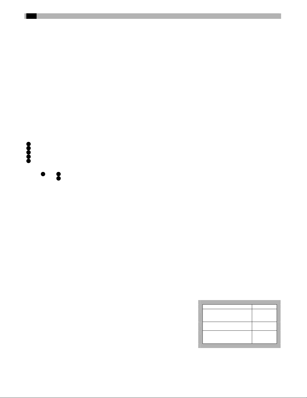
10. Maintenance.
Caution! Before embarking on any maintenance work, switch current off to the enclosure.
The cooling unit is the low maintenance type so
no filter change is required. The only jobs that
need doing are the internal components with
compressed air at a maximum pressure of 4 bar
(figure F.54.1) and which should be checked
regularly.
Job Frequency
Check the external air heat
exchanger and clean if
Every 3
months
necessary
Check effectiveness of the
condensate discharge
Check the fans for any
overheating or excessive
Every 3
months
Every 6
months
vibrations
Any repairs that may need doing must only be
done by specialised and authorised personnel
and using original spare parts only.
4
 Loading...