

Page 1
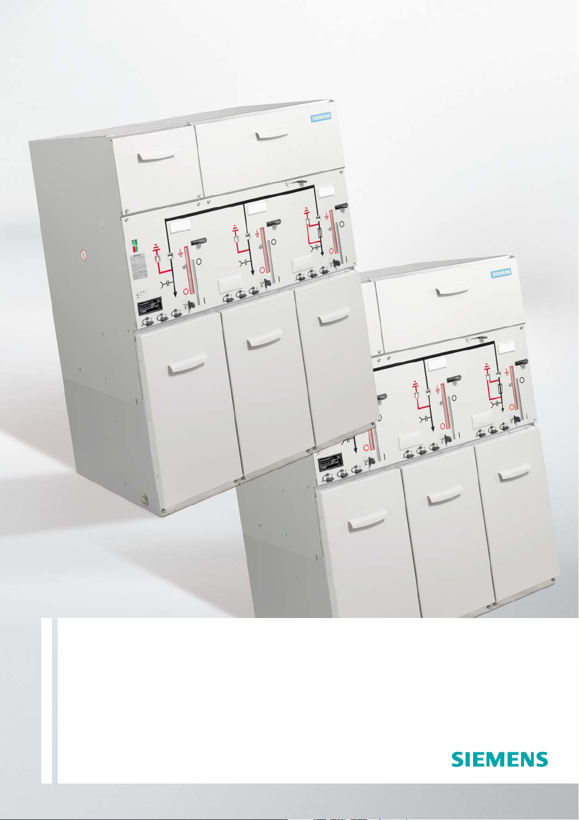
Switchgear Type 8DJ20
up to 24 kV, Gas-Insulated
Medium-Voltage Switchgear
Catalog HA 45.31 · 2008
www.siemens.com/energy
Page 2

Contents
Application, Requirements
Features
Application, Requirements
Page
Features, typical use 2 and 3
Technical Data
Electrical data, filling pressure, temperature 4
Product Range
Equipment features 4
Product range overview, schemes 5
Design
Panel design 6
Components
Three-position switch-disconnector,
operating mechanisms 7
HV HRC fuse assembly, secondary
equipment, pressure absorber system 8
Cable connection 9
Dimensions
Switchgear 10 to 13
Floor openings, fixing points 14 and 15
Examples for cable connection 16
Shipping
Types of transport, transport data 17
Designs, Special Designs
LV compartment, outdoor enclosures 18 to 20
Standards, Notes
Standards, specifications,
guidelines, classification 21 to 23
For further information, please refer to
•
Catalog HA 40.1:
Switchgear Types 8DJ and 8DH, General Part
•
HA 45.31/41.11:
Supplements to Switchgear Types 8DJ and 8DH
Invalid:
Catalog HA 45.31 · 2006
The products and systems describedin this catalog
are manufactured and sold according to a certified
quality and environmental managementsystem
(acc. to ISO 9001 and ISO 14001).
(DQS Certificate Reg. No. DQS 003473 QM UM).
The certificate is accepted in all IQNet countries.
8DJ20 switchgear is a factoryassembled, type-tested, metalenclosed switchgear for indoor
installation.
Typ ic al us es
8DJ20 switchgear is used for
power distribution in substations
– even under severe environmen
tal conditions, such as:
Industrial environments
•
Damp, sandy or dusty areas
•
Simple outdoor substations
•
Main uses
Compact substations
•
Compact transformer substations,
•
e. g. for wind power stations
Garage and vault substations
•
Underground and underfloor
•
substations
Sidewalk substations, e.g.
•
containing switchgear with a
very small overall width – in
particular the basic versions
of schemes 10, 32 and 71 –
in conurbations
•
Substations with control aisle
Technology
•
Switchgear design with up to
5 feeders
•
Maintenance-free
•
Climate-independent
•
Partition class: PM
(metallic partition)
•
Three-pole primary enclosure,
metal-enclosed
•
Insulating gas SF
•
Welded switchgear vessel with-
6
out seals, made of stainless
steel, with welded-in bushings
for electrical connections and
mechanical components
•
Three-position switch-discon
nector with load-break and
make-proof earthing function
•
Cable connection for
bushings with outside cone
•
Connection with cable plugs
– In ring-main feeders with
bolted contact (M16)
– In transformer feeders with
plug-in contact
Option: Connection with
•
conventional sealing ends
– For thermoplastic-insulated
cables via elbow adapter
AKE 20/630 (make Siemens)
– For paper-insulated mass-im-
pregnated cables via commercially available adapter systems
Easy installation
•
-
Personal safety
Safe-to-touch and hermetically-
•
sealed primary enclosure
HV HRC fuses and cable sealing
•
ends are only accessible when
outgoing feeders are earthed
Operation only possible when
•
enclosure is closed
Logical mechanical interlocking
•
Capacitive voltage detecting
•
system to verify safe isolation
from supply
Feeder earthing by means of
•
make-proof earthing switches
Security of operation
Hermetically-sealed primary
•
enclosure independent of environmental effects such as
pollution, humidity and small
animals – sealed for life:
– Welded switchgear vessel
– Welded-in bushings and
operating mechanism
•
Operating mechanism parts
maintenance-free
(IEC 62 271-1/VDE 0671-1)
•
Operating mechanisms of
switching devices located out-
side the switchgear vessel
(primary enclosure)
•
Switchgear interlocking system
with logical mechanical inter-
locks
Cost-efficiency
Extremely low “life-cycle costs”
throughout the entire product
service life as a result of:
•
Maintenance-free concept
•
Climatic independence
•
Minimum space requirements
•
Maximum availability
Standards
seepage21
© Siemens AG 2008
Switchgear Type 8DJ20 up to 24 kV, Gas-Insulated· Siemens HA 45.31 · 2008
2
Page 3
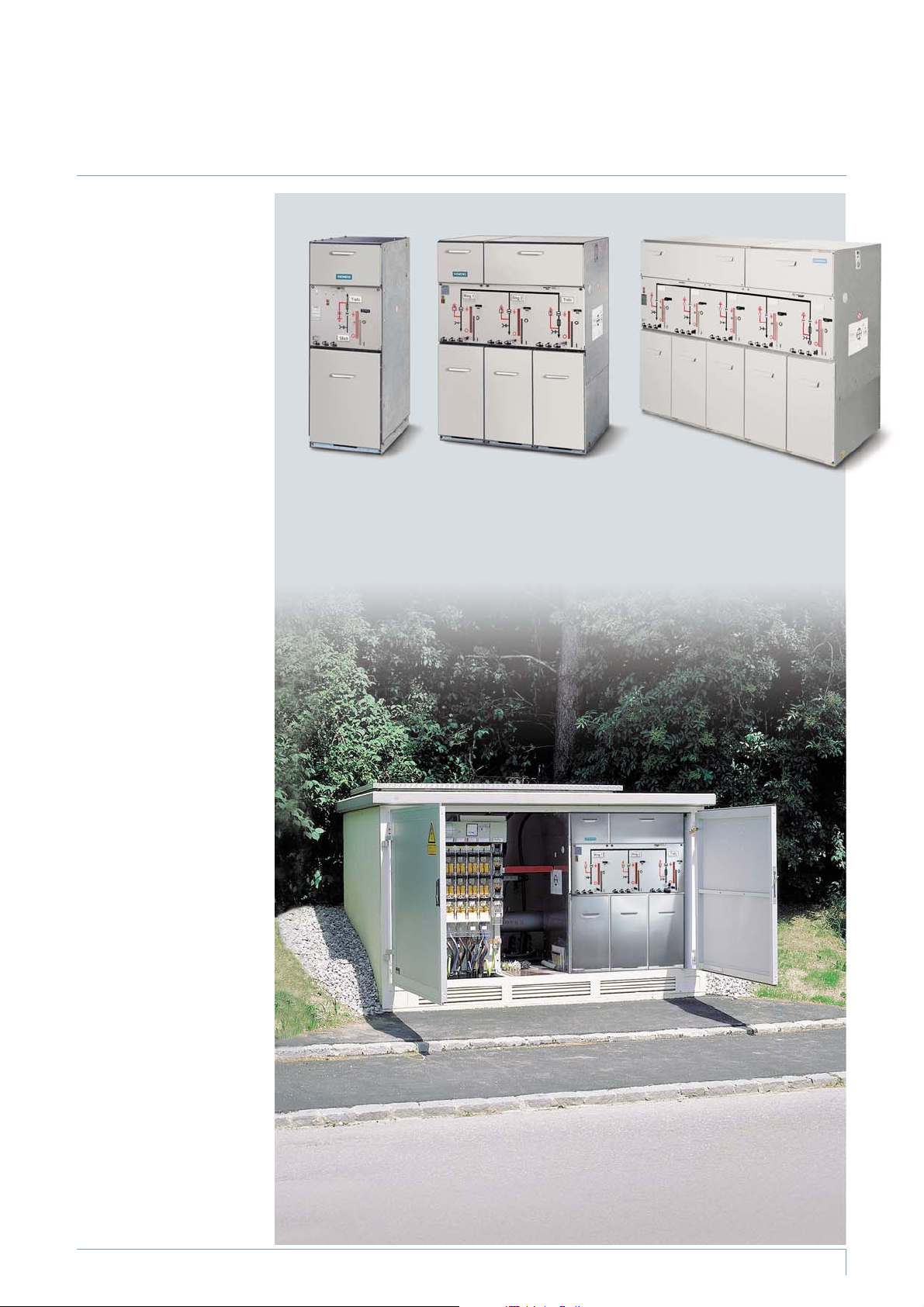
Application
Features
Our product range extends from
switchgear installed in a radial
transformer panel (individual
panel) to switchgear with 5
feeders, consisting of
Ring-main feeders
•
Transformer feeders with
•
HV HRC fuse assemblies
Circuit-breaker feeders (for
•
thecompleteproductrange
see Supplements to Catalogs
HA 45.31/41.11 – 2006)
The switchgear is available in
three overall heights:
1200 mm
•
(with low subframe)
1400 mm and 1760 mm
•
(with high subframe)
These overall heights cover all
areas of application, from compact substations to switchgear
rooms with control aisle.
Basic design
Manual operating mechanism
•
Transformer cable connection
•
at the front (standard)
•
With logical mechanical interlocks
•
With ready-for-service indicator
•
With capacitive voltage detecting system at the ringmain feeders
s
p
e
c
9
9
0
5
4
A
H
R
Radial transformer
panel
1 transformer feeder
1 radial cable connection
Scheme 01
s
p
e
b
0
0
1
5
4
A
H
R
Ring-main/
transformer block
2 ring-main feeders
1 transformer feeder
Scheme 10
s
p
e
c
1
0
1
5
4
A
H
R
Ring-main/
transformer block
3 ring-main feeders
2 transformer feeders
Scheme 82
Typical use
Options (others on request)
•
Capacitive voltage detecting
system at the transformer
feeders
•
Motor operating mechanisms
for the three-position switchdisconnectors
•
Auxiliary switch for three-position switch-disconnector and
make-proof earthing switch
•
Short-circuit indicator with
built-in housing
•
Surge arresters for ring-main
feeders
•
Shunt releases for transformer
feeders
•
Secondary equipment for
remote operation or remote
indication, e.g. with localremote switch in the case of
motor operating mechanisms
or ”tripped signal” in the case
of transformer feeders
•
Locking devices
•
Closing lock-out
•
De-earthing lock-out
•
Cable clamps
s
p
e
c
6
8
0
5
4
A
H
R
8DJ20 switchgear in
a compact substation
Switchgear Type 8DJ20 up to 24 kV, Gas-Insulated· Siemens HA 45.31 · 2008
3
Page 4
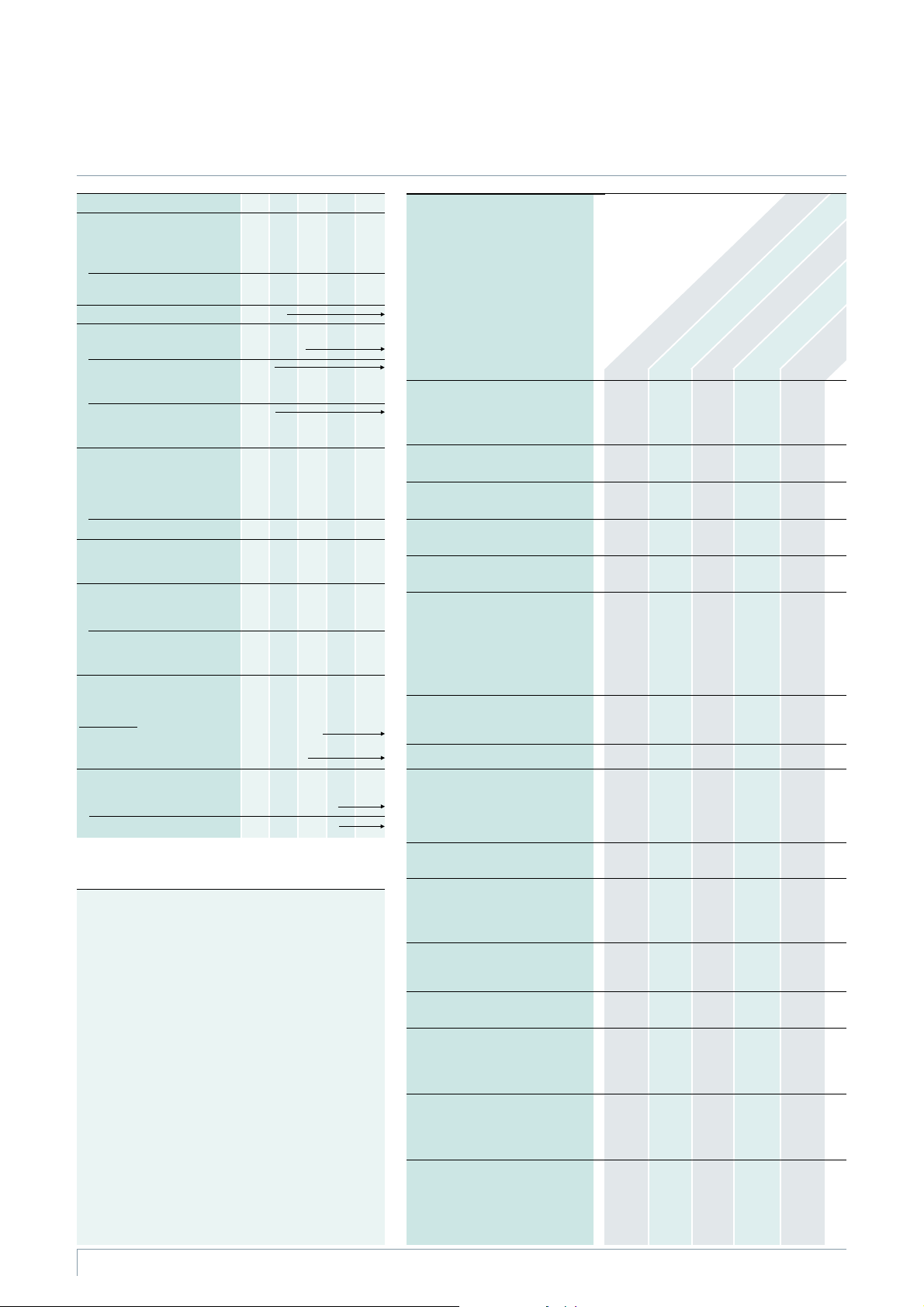
Technical Data, Product Range
Electrical data, temperature, filling pressure Equipment features of panels
Rated voltage U
Rated insulation level
Rated short-duration kV
power-frequency
withstand voltage U
Rated lightning impulse kV
withstand voltage U
Rated frequency f
Rated normal current I
for ring-main feeders 400 or 630 A
for transformer feeders
depending on the
HV HRC fuse link
for schemes 01 and 21
depending on the
HV HRC fuse link
Rated short-time
withstand current I
at 1 s kA
at 3 s (option) kA 20 20 20 20 20
Rated peak kA
withstand current I
Rated short-circuit
making current I
fortransformerfeeders kA2525252525
for ring-main feeders kA
Ambient air temperature T
(operating conditions acc. to
IEC 62 271-200/Clause 2 or
IEC 62 271-1
– Without secondary equipment
– With secondary equipment,
class “Minus 5 indoor”
Pressure values at 20 °C
for the insulation:
Rated filling level p
Minimum functional level p
1) According to some national requirements, higher values of the
rated short-duration power-frequency withstand voltage
available for I
– 42 kV for phase-to-phase, phase-to-earth and opencontact
gap as well as
– 48 kV across the isolating distance
Higher values of the rated lightning impulse withstand voltage:
– 95 kV for phase-to-phase, phase-to-earth and opencontact
gap as well as
– 110 kV across the isolating distance
2) For overall height of switchgear 1200 mm:
Cable bracket below the feeder
3) Cable fixing by customer
(the switchgear is supplied without cable bracket)
4) In case of scheme 01 the cable compartment cover is bolted.
The transformer connection is effected via the bushings
arranged underneath the switchgear vessel. The transformer
feeder is earthed by the three-position switch
5) Temperature range, reduced normal currents at ambientair
temperatures>+40°C
6) SurgearrestertypeRDAwithRICS(TycoElectronics)not
possible for a height of 1200 mm
o. r. = on request
r
r
ma
)
=20kAwith:
k
k
p
re
kV 7.2121517.524
20 281)36 38 50
d
p
r
60 751)95 95 125
50/60 Hz
200 A
200 A
–
kA
kA
kA
kA
kA
kA
me
–
20
20
25
25
–
–
50
50
63
63
–
–
50
50
63
63
-40to+70°C
-5to55°C
1500 hPa (absolute)
1300 hPA (absolute)
–
16
20
25
–
50
63
–
50
63
5)
5)
16
20
20
25
–
40
40
50
50
63
–
40
40
50
50
63
–
Equipment
Manual operating mechanism for
three-position switch-disconnector:
– As spring-operated mechanism
– As spring-operat./stored-energy mech.
Motor operating mechanism for
three-position switch-disconnector
Interlock for cable compartment
cover
Cable compartment cover locked
in place/screwed on
2)
Cable bracket
feeders, cable routing downwards
Cable bracket in transformer feeder:
For cable routing
– Downwards (standard), f. cable elb. plugs
or
– Downwards, for straight cable plugs
or
– To the rear, for cable elbow plugs
Low-voltage terminals in the
operating mechanism
(option for secondary equipment)
Shunt release
Auxiliary switch for
– Switch-disconnector
CLOSED/OPEN:1NO+2NC
–EARTHINGCLOSED/OPEN:
1NO+1NC
Locking device for
three-position switch-disconnector
Short-circuit or earth-fault indicator
– Wiring at the indicator
(standard)
– Wiring to terminal (option)
De-earthing lock-out for
make-proof earthing switch
in transformer feeder
Closing lock-out for
three-position switch-disconnector
Double cable connection for
– Overall height of switchgear 1200 mm
– Overall height of switchgear 1400 mm
– Overall height of switchgear 1760 mm
Surge arrester for
– Overall height of switchgear 1200 mm
– Overall height of switchgear 1400 mm
– Overall height of switchgear 1760 mm
Cable clamps for cable fixing
– Supplied separately
– Preassembled (option)
in ring-main and cable
• Basic equipment
Additional equipment
°
(option), further
additional equipment
on request
xNot
applicable
– Not avail-
able
Radial cable connection, panel K(E) for scheme 21
(with additional earthing switch)
Radial cable connection,panelKforscheme02
Ring-main feeders
panel RK
(without earthing switch)
•
x
–
x
–x
•
–•••
–•–––
••••
x
x
x
x
x
x
•–•••
–––
x
°
x
°
x
°
°
°
°
°
xxx
°
–x
°
°
°
°
°
°
–
–
°
°
°
°
°
°
°
°
Transformer feeder
panel1Tinscheme01
Transformer
•
–
–
•
°°°
x
x
x
•
without
3)
without
3)
x
°°
°
°
°
°
°°°
–
°
–
°
4)
––
°
x
°
x
°
x
°
6)
o. r.
x
x
°
x
°
°
°
–
°
feeders
–
•
x
•
•
°
°
–
–
°
x
x
x
x
x
x
°
°
panel T
Switchgear Type 8DJ20 up to 24 kV, Gas-Insulated· Siemens HA 45.31 · 2008
4
Page 5
T
HA45-2294d eps
K
HA45-2295c eps
RK K
HA45-2296c eps
RK TRK
HA45-2302c eps
RK TRK RK
HA45-2304c eps
RK TRKT
HA45-2297c eps
RK RK
HA45-2301c eps
RK RKRK RK
RK RKRK RK RK
HA45-2306c eps
HA45-2300c eps
RK RKRK
HA45-2305c eps
RK TRKT RK
HA45-2303c eps
RK TRK RK RK
HA45-2298c eps
TRK
HA45-2299c eps
TK(E)
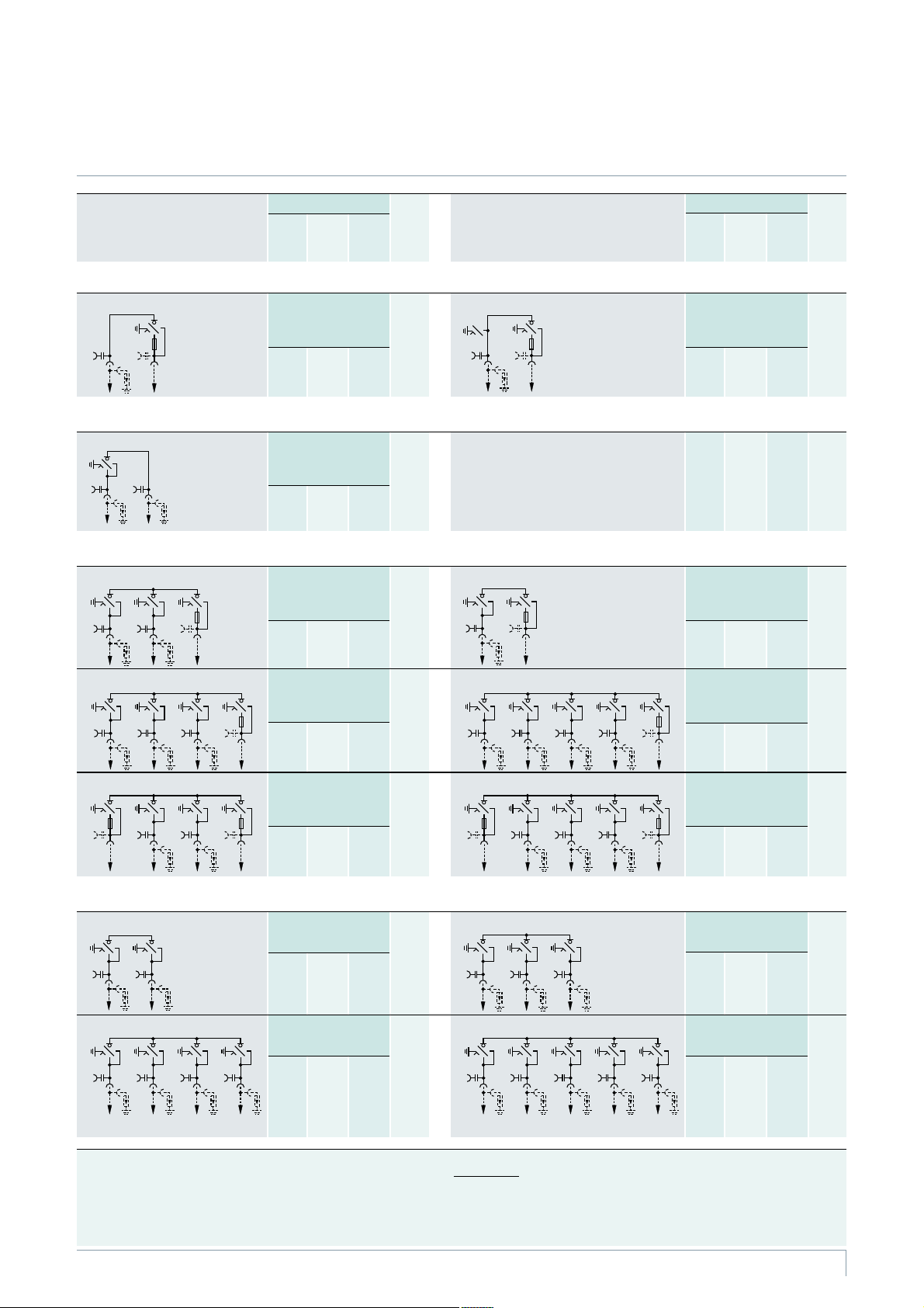
Product Range
Product range overview, schemes
1)
Scheme
Components shown in dotted
lines can be used optionally.
Overall dimensions Net
WidthmmDepth
2) 3)
mm
Height
mm
weight
approx.
kg
Scheme
Components shown in dotted
lines can be used optionally.
Radial transformer panels
Scheme 01 * 1 transformer feeder,
K Radial cable
connection as
infeed
1 radial cable connection
(Abbreviation 1T)
510 775 1200
1400
1760
140
160
200
Scheme 21 1 radial cable connection,
Radial panel
Scheme 02 1 ring-main feeder with
radial cable connection
(Abbreviation 1RK)
710 775 1200
1400
1760
150
170
210
Block versions, consisting of ring-main andtransformer feeders (with HV HRCfuse assembly)
Scheme 10
* 2 ring-main feeders,
Scheme 20 1 ring-main feeder,
1 transformer feeder
(Abbreviations 2RK+1T)
1060 775 1200
1400
1760
280
300
340
K(E) Radial cable
connection, K as
K(E) with make-proof
earthing switch
Overall dimensions Net
WidthmmDepth
2) 3)
mm
Height
mm
weight
approx.
kg
1 transformer feeder
(Abbreviations 1K(E)+1T)
710 775 1200
1400
1760
200
210
250
1 transformer feeder
(Abbreviations 1RK+1T)
710 775 1200
1400
1760
200
210
250
1)
Scheme 71 * 3 ring-main feeders,
1 transformer feeder
(Abbreviations 3RK+1T)
1410 775 1200
1400
1760
340
360
400
Scheme 81 * 2 ring-main feeders,
2 transformer feeders
(Abbreviations 2RK+2T)
1410 775 1200
1400
1760
400
420
460
Block versions, consisting of ring-main feeders (withoutHV HRC fuse assembly)
Scheme 11 2 ring-main feeders
(Abbreviation 2RK)
710 775 1200
1400
1760
160
170
210
Scheme 70 * 4 ring-main feeders
(Abbreviation 4RK)
1410 775 1200
1400
1760
280
300
340
Scheme 72 4 ring-main feeders,
1 transformer feeder
(Abbreviations 4RK+1T)
1760 775 1200
Scheme 82 3 ring-main feeders,
2 transformer feeders
(Abbreviations 3RK+2T)
1760 775 1200
Scheme 32
* 3 ring-main feeders
(Abbreviation 3RK)
1060 775 1200
Scheme 84 5 ring-main feeders
(Abbreviation 5RK)
1760 775 1200
1400
1760
1400
1760
1400
1760
1400
1760
420
440
480
470
500
540
210
230
270
350
380
420
1) Depending on the relevant equipment, e.g. motor operating mechanism
2) Additional wall distance required: W 15 mm
3) For cable routing of transformer cables downwards
* Scheme is also suitable for outdoor enclosure (see pages 18 and 19)
Abbreviations:
RK = Ring-main feeder K = Cable feeder T = Transformer feeder
K(E) = Cable feeder forradial cable connection with make-proofearthing switch
Switchgear Type 8DJ20 up to 24 kV, Gas-Insulated· Siemens HA 45.31 · 2008
5
Page 6
HA45-2337d eps
L1 L2 L3
5
3
2
1
4
B
A
B
A
6
7
8
9
10
11
12
13
14
15
17
18
19
20
21
22
23
24
25
26
27
28
10
19
20
31
22
23
32
24
27
33
31
36
10
16
30
29
34
35
38
38
HA45-2308e eps
31
32
29
24
30
22
HA45-2309e eps
31
32
29
22
23
24
37
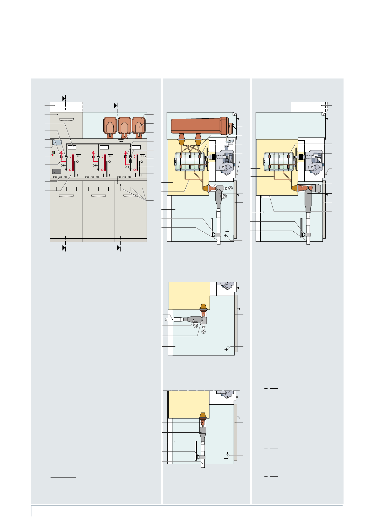
Design
Panel design (example)
Ring-main/transformer block
Scheme 10
Transformer feeder
Section A-A
Standard
Cable connection for cable elbowplugs
(option: for cable T-plugs),
cable routing downwards
Ring-main feeder
Section B-B
Cable connection with bolted contact (M16):
– For cable T-plug or cable elbow plug
– For conventional cable sealing ends via
elbow adapter AKE 20/630
1 Niche for customer-side low-voltage equipment
2 Feeder designation label
Position indicators
in the ring-main feeder:
3 Load-break function ”CLOSED – OPEN”
4 Earthing function ”OPEN – EARTHED”
5 Rating and type plate
6 Ready-for-service indicator
7 Mimic diagram
8 Short-circuit/earth-fault indicator (option)
9 Sockets for voltage detecting system
10 Interlock of the cable compartment cover
11 HV HRC fuse assembly, cover removed
12 Handle for replacing the HV HRC fuse link
13 Interlock for HV HRC fuse assembly
Position indicators
in the transformer feeder:
14 Earthing function ”OPEN – EARTHED”
15 Load-break function ”CLOSED – OPEN”
with ”HV HRC fuse tripped” or”shunt release
tripped”, where applicable
16 Locking device
(option for three-position switch-disconnector)
17 Manual operation for the mechanism of
the earthing function
Personal safety
All feeder-related covers can only be
opened if the associated three-position
switch-disconnector has been switched to
the “EARTHED” position.
Switchgear Type 8DJ20 up to 24 kV, Gas-Insulated· Siemens HA 45.31 · 2008
6
Option
Cable connection for cable elbow
plugs, cable routing tothe rear
(cable fixing by customer)
Option
Cable connection for
straight cable plugs,
cable routing downwards
18 Manual operation for the mechanism of
the load-break function
19 Switchgear vessel, filled with gas
20 Connecting bar to cable connection
21 Arrangement of cable connections
22 Cable compartment
23 Cable bracket
24 Cable (not included in the scope ofsupply)
25 Cover of the HV HRC fuse compartment
26 Connecting bar to the bushings
for the HV HRC fuse
27 Three-position switch-disconnector
28 Spring-operated/stored-energy mechanism
29 Bushing as interface type “A” for
cable plug with plug-in contact
O
ption: Bushing as interface type “C”
for cable plug with bolted contact (M16)
30 O
ption: Cable elbow plug with
plug-in contact
31 Cable compartment cover
32 M12 earthing connection
33 Spring-operated mechanism
34 Bushing as interface type “C“ for cable
plug with bolted contact (M16)
35 O
ption: Cable T-plug with bolted contact
36 Pressure relief device
37 O
ption: Straight cable plug with
plug-in contact
ption: Low-voltage compartment
38 O
Page 7
Components
Three-position switch-disconnector, operating mechanisms
Three-position
switch-disconnector
The switching device used
is the proven three-position
switch-disconnector
Functions
Load-break function
•
Earthing function with
•
short-circuit making capacity
Switch positions
•
CLOSED – OPEN – EARTHED
Operating mechanisms
The three-position switchdisconnector is operated from
the switchgear front via
Detachable lever mechanism
(standard)
• Spring-operated mechanism
– With ”spring-operated
CLOSED” and ”spring-operated OPEN” for installation
in ring-main feeders
Spring-operated/stored-
•
energy mechanism
– With ”spring-operated
CLOSED” and ”spring-operated OPEN” for installation
in transformer feeders
–Withanadditionalenergy
store for the function ”storedenergy OPEN” after tripping
by the HV HRC fuse (striker
tripping) or by the shunt
release
ptions
O
•
Motor operating mechanism
for switch-disconnector
•
Rotary operating mechanism
•
Locking devices
•
Auxiliary contacts for three
position switch-disconnector
and make-proof earthing
switch
•
Shunt release for transformer
feeders
•
Closing lock-out for ringmain feeders
•
De-earthing lock-out for
transformer feeders
•
Different operating levers1)for
the operating mechanisms of
the switch-disconnector and of
the make-proof earthing switch
1) According to VDN */VDEW**
recommendation
* AssociationofGermanNetwork
Operators VDN e.V. at the VDEW in
Germany (as of 2003)
** Association of German
Power Stations – VDEW e.V.
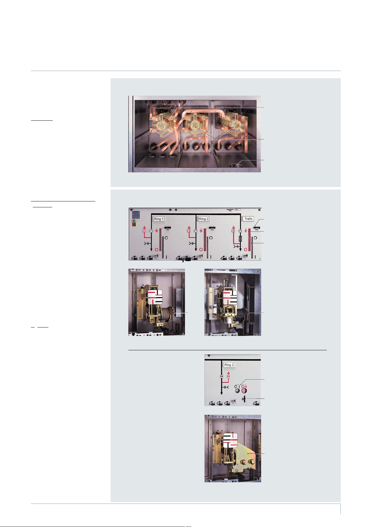
Three-position switch-disconnector
s
p
e
2
0
1
5
4
A
H
R
Switchgear vessel of a
ring-main/transformer
block, scheme 10
1
(rear view)
1 Three-position switch-
disconnector in the
transformer feeder
2 Three-position switch-
2
disconnector in the
ring-main feeders
3 Pressure relief device
3
Operating mechanisms
s
p
e
a
3
0
1
5
4
A
H
R
s
p
e
4
0
1
5
4
A
H
R
s
p
e
5
0
1
5
4
A
H
R
7
s
p
e
a
6
0
1
-
5
4
A
H
R
s
p
e
7
0
1
5
4
A
H
R
Control board for detachable lever mechanisms
(standard)
4
Example:
Ring-main/transformer block,
5
scheme 10
4 Locking device (option)
6
for the detachable lever
mechanism
5 Detachable lever
operation for the
earthing function
6 Detachable lever
operation for the
load-break function
7 Detachable lever
mechanism for the
ring-main feeder
8 Detachable lever
8
mechanism for the
transformer feeder
Control board for rotary
operating mechanisms
(option)
Example: Ring-main feeder
9
9 Symbols for the actuating
direction of the rotary
operating mechanism
10 Locking device for the ro-
10
tary operating mechanism
11 Rotary operating
mechanism (option)
11
Switchgear Type 8DJ20 up to 24 kV, Gas-Insulated· Siemens HA 45.31 · 2008
7
Page 8
HA45-2364 eps
1400
~2
880
³
15
775
240
435
~560
2
3
5
1
4
HA45-2363 eps
~1762
880
³
15
775
240
435
~560
5
1
2
3
4
Components
HV HRC fuse assembly, secondary equipment, pressure absorber system
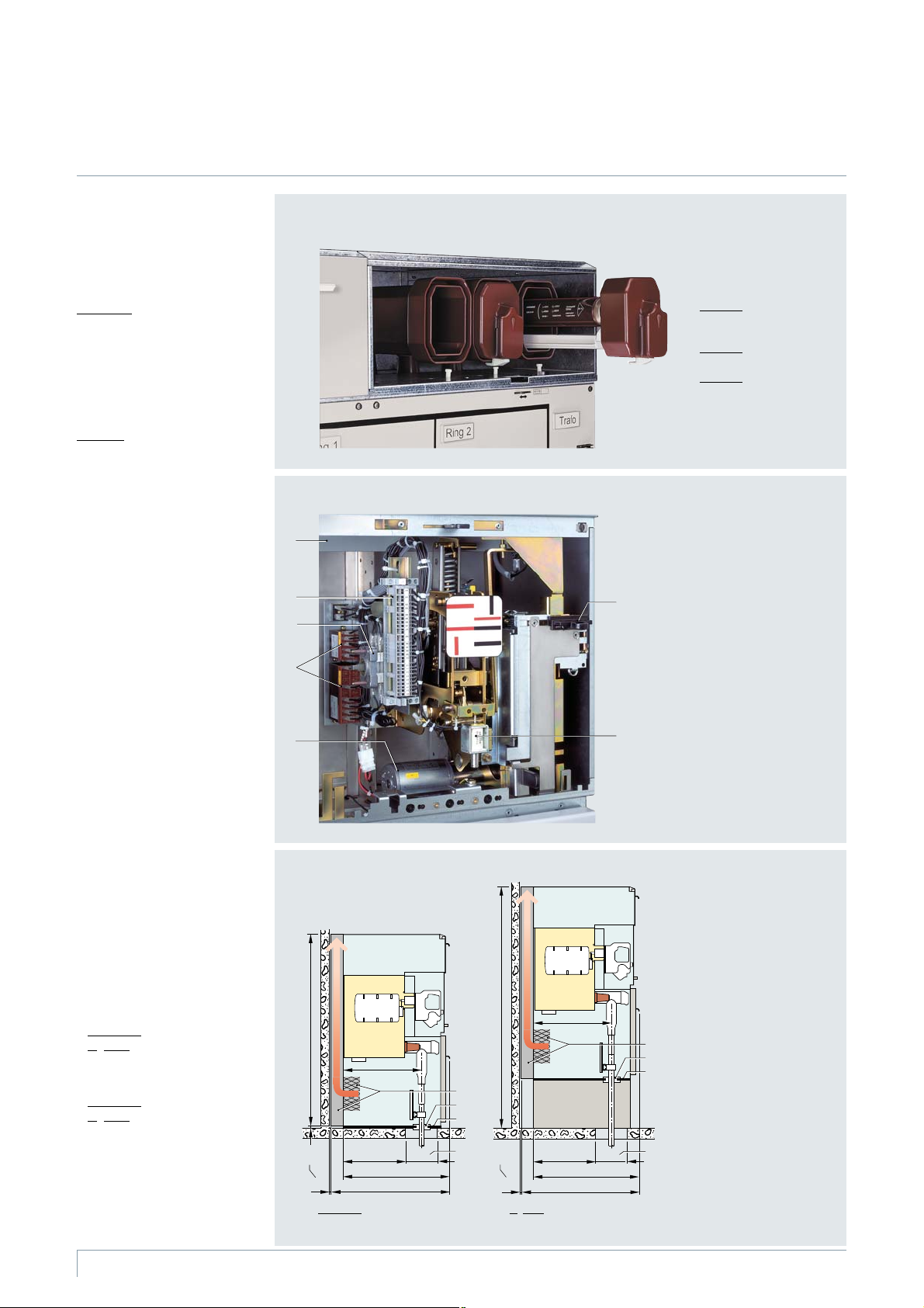
HV HRC fuse assembly
The HV HRC fuse boxes are
single-phase insulated and located above the transformer
feeder outside the switchgear
vessel.
Standards
(see page 21)
HV HRC fuse links with striker in
“medium” version according to
IEC 60 282-1
•
VDE 0670 Parts 4 and 402
•
DIN 43 625 main dimensions
•
Features
Requirements fulfilled as HV
•
alternating current switchfuse combination
Selection of HV HRC fuses for
•
transformers
For further features
•
see Catalog HA 40.1
Secondary equipment (option)
Auxiliary switches, motor
•
operating mechanisms or
shunt releases wired to a
terminal strip
•
Location of the terminal strip
next to the operating mechanism module of the feeder
concerned
•
Customer-side cable routing
to the terminal strip from the
side or rear
Pressure absorber system
(option)
•
Maintenance-free
•
For all schemes (except radial
transformer panel, scheme 01)
•
For rated short-time with
stand current I
with IAC (internal arc
w 16 kA,
k
-
classification, see page 22)
•
With 105 mm deep pressure
relief duct for pressure relief
upwards
•
For overall height of switch-
gear:
–Standard:
–O
•
For wall-standing arrangement
•
Transformer cable routing:
–Standard:
–O
schemes 10, 71 and 72
•
Weight approx. 110 kg
1400 mm
ption: 1760 mm
Downwards
ption: To th e r ear for
HV HRC fuse compartment
s
p
e
8
0
1
5
4
A
H
R
Secondary equipment (option)
1
2
3
4
5
s
p
e
3
3
1
5
4
A
H
R
Pressure absorber system
(option)
Standard: Overall height 1400 mm
6
7
O
ption: Overall height 1760 mm
HV HRC fuse compartment
with cable compartment
cover removed
Phase L1:
HV HRC fuse box with
HV HRC fuse slide removed
Phase L2:
HV HRC fuse box closed
Phase L3:
Replacement of HV HRC fuses
Auxiliary switch, motor
operating mechanism and
shunt release
Example: Transformer feeder
1 Wiring duct
2 Te rm ina l str ip
3 Auxiliary switch at spring-
operated mechanism of a
ring-main feeder
4 Auxiliary contactors
(standard for motor
operating mechanism)
5 Motor operating mechanism
at spring-operated/
stored-energy mechanism
6 Locking device
(standard for motor
operating mechanism)
7 Shunt release at spring-
operated/stored-energy
mechanism
Sectional views of the
pressure absorber system
1 Wall distance
2 Pressure absorber system
with rear pressure relief
duct directed upwards
3 Cable bushing
4 Divided floor plate for
cable entry for on-site
installation
5 Floor opening for the
cable feeder
8
Switchgear Type 8DJ20 up to 24 kV, Gas-Insulated· Siemens HA 45.31 · 2008
Page 9

Bushings according to
•
EN 50 181/DIN EN 50 181
with outside cone
Cable connection at one level
•
Access to the cable compart
•
ment only if the feeder has
been isolated and earthed
Ring-main cable connection
With bolted contact (M16) as
•
interface type ”C” according
to EN 50 181/DIN EN 50 181
For thermoplastic-insulated
•
cables
For paper-insulated mass-
•
impregnated cables with
adapter systems
For conventional cable sealing
•
ends via elbow adapters
AKE 20/630 (make Siemens)
ForcableT-plugsorcable
•
elbow plugs with bolted
contact (M16)
For connection cross-sections
•
up to 300 mm
Cable routing downwards,
•
2
(standard)
cable connection at front
•
For rated normal currents of
400/630 A
O
ptions
•
Suitable for the connection of
surge arresters
•
Short-circuit/earth-fault
indicator
•
Mounted cable clamps
•
Double cable connection with
corresponding cable plugs
Components
Cable connection
1)
-
Cable connection (examples)
L1
1
s
p
e
1
1
1
5
4
A
H
R
Cable compartment,
as delivered
L1
5
s
p
e
3
1
1
5
4
A
H
R
Cable compartment,
as delivered
L3
L2
L3
L2
L1
2
3
4
s
p
e
8
2
1
0
4
A
H
R
Cable plugs with
bolted contact (M16)
L1
6
7
8
s
p
e
4
1
1
5
4
A
H
R
Cable elbow plugs with
plug-in contact
L3
L2
Cable connections
in ring-main feeder
1 Prepared for cable plugswith
bolted contact (M16)
2 Phase L1:
Make: Euromold
type K400 LB
as cable elbow plug
3 Phase L2:
Make: Euromold
type K400 TB
as cable T-plug
4 Phase L3:
Make: Euromold
type AGT 20/630
as cable T-plug
ption:
O
Mounted cable clamps
L3
L2
Cable connections
in transformer feeder
5 Prepared for cable elbowplugs
with plug-in contact
6 Phase L1:
Make: Euromold
type K158 LR
7 Phase L2:
Make: nkt cables
type EASW 20/250
8 Phase L3:
Make: Cooper
type DE 250-R-C
ption:
O
Mounted cable clamps
Transformer cable connection
•
With plug-in contact as inter-
face type “A” according to
EN 50 181/DIN EN 50 181
•
For cable elbow plugs
(standard) or straight cable
plugs with plug-in contact
•
For thermoplastic-insulated
cables
•
For connection cross-sections
up to 120 mm
•
For rated normal currents
2
of 200 A
O
ptions
•
With bolted contact (M16) as
interface type “C” according
to EN 50 181/DIN EN 50 181
•
Mounted cable clamps
•
Cableroutingtotherear
(for cable elbow plugs)
Transformer cable connection for cable plugs
Standard:
ption: With bolted contact (M16) as interface type “C”
O
Arrangement of
connections
For all schemes (except scheme 01)
At the front
(standard)
At the bottom
(option)
Only for scheme 01 (radial transformer panel 1T)
At the bottom
(standard)
1) Standard EN 50 181/DIN EN 50 181:
“Plug-in bushings above 1 kV up to
36 kV and from 250 A to 1.25 kA for
equipment other than liquid-filled
transformers.”
With plug-in contact as interface type “A”
Cable routing Cable plug
Downwards Cable elbow plug with plug-in contact
To the rear
Downwards Straight cable plug with plug-in contact
To the rear
Downwards (option) Straight cable plug with plug-in contact
2)
2)
(standard) Cable elbow plug with plug-in contact
Switchgear Type 8DJ20 up to 24 kV, Gas-Insulated· Siemens HA 45.31 · 2008
version
ption: Cable plug with bolted contact (M16)
O
Cable elbow plug with plug-in contact
ption: Straight cable plug with bolted contact (M16)
O
ption: Straight cable plug with bolted contact (M16)
O
2) For cable routing of the transformer feeder to the rear:
Cable fixing by customer
Cable plugs, cable
sealing ends and cable
clamps are not included
in the scope of supply.
9
Page 10

220/420
**
***
M12
~520*, ~560
*
750
775
367
515
375/ 575
**
a
1
2
HA45-2312h eps
A
A
710
K (E)
T
350 350
B
B
1200/1400
375/ 575
**
~560
750
775
553
a
1760
935
935
780
1200/ 1400
T
B
B
HA45-2345e eps
510
4
1760
500
220/ 420
**
***
M12
~520*, ~560
*
750
775
375/ 575
**
a
1
2
515
935
780
***
M12
~520*, ~560
*
750
775
375/ 575
**
240
a
515
1
3
935
Dimensions
Switchgear (for floor openings and fixing points refer to page 14)
Radial transformer panels · optionally in 3 overall heights
Section B-B Section B-B
Tra nsf orm er
feeder T
Cable routing
of feeder
to the rear
with cable
elbow plugs
(on request)
Scheme 01
(with radial cable
connection as infeed)
1 Bushing at the front for cable routing downwards (infeed)
Standard:
O
2 Bushing at the bottom as interface type “A” with plug-in contact
for cable routing to the rear (feeder T)
3 Bushing at the bottom as interface type “A” with plug-in contact
for cable routing downwards (feeder T)
4 Bolted joint of cable compartment cover (only for scheme 01)
For cable elbow plugs with plug-in contact
ption: For cable T-plugs with bolted contact(M16)
* Dimension depending on the bushing size and make/type of cableplug
** Dimensions depending on the overall heights of switchgear 1200 and 1400 mm
*** For cable routing to the rear, the depth dimensions are 10 mmdeeper
BB Dimension for bushing as interface type “A” with plug-in contact
Tra nsf orm er
feeder T
Cable routing
of feeder
downwards
with straight
cable plugs
Dimension a
–40mmfor
overall height 1400 mm
– 130 mm for
overall height 1200 mm
Section B-BSection A-A
Radial cable
connection K(E)
with make-proof
earthing switch
Scheme 21
1 Bushing at the front (standard) for cable routingdownwards
2 Bushing at the bottom (option) for cable routing to the rear or
downwards
** Dimensions depending on the overall heights ofswitchgear 1200 and 1400 mm
*** For cable routing to the rear, the depth dimensions are 10 mm deeper
B Dimension for bushing as interface type “C” with bolted contact (M16)
BB Dimension for bushing as interface type “A” with plug-in contact
* Dimension depending on the bushing size and make/type of cable plug
Tra nsf orm er
feeder T
Dimension a
–40mmfor
overall height 1400 mm
– 130 mm for
overall height 1200 mm
10
Switchgear Type 8DJ20 up to 24 kV, Gas-Insulated· Siemens HA 45.31 · 2008
Page 11

A
A
710
RK
350
RK
350
A
A
1060
RK
350
RK RK
350 350
A
A
1410
1200/ 1400
RK
350
RK RK RK
350 350 350
1760
A
A
710
RK
350 350
HA45-2315f eps
4
375/ 575
**
~560
750
775
553
a
935
HA45-2319f eps
A
A
1760
1200/ 1400
RK
350
RK RK RK RK
350 350 350 350
1760
Switchgear (for floor openings and fixing points refer to page 14)
Block versions, consisting of ring-main feeders · optionally in 3 overall heights
Section A-A
Scheme 84
Dimensions
Ring-main
feeder RK
Dimension a
–40mmfor
overall height 1400 mm
– 130 mm for
overall height 1200 mm
** Dimensions depending on the overall heights ofswitchgear 1200 and 1400 mm
B Dimension for bushing as interface type “C” with bolted contact (M16)
Further scheme types (sideviews,sectionA-A,seescheme84)
Scheme 02 (1RK with
radial cable connection)
4 Bolted joint of cable compartment cover
Scheme 11 Scheme 32 Scheme 70
Switchgear Type 8DJ20 up to 24 kV, Gas-Insulated· Siemens HA 45.31 · 2008
11
Page 12

HA45-2321e eps
A
710
RK
T
B
A
350 350
B
A
1060
RK RK
T
B
A
350 350 350
B
A
1410
1200/ 1400
RK RK RK
T
B
A
350 350 350 350
B
1760
375/ 575
**
~560
750
775
553
a
935
HA45-2324f eps
A
A
1760
1200/ 1400
RK
350
RK RK RK
T
350 350 350 350
B
B
1760
220/ 420
**
***
M12
~520*, ~560
*
750
775
367
515
375/ 575
**
a
1
2
935
780
Dimensions
Switchgear (for floor openings and fixing points refer to page 15)
Block versions, consisting of ring-main feeders and 1 transformer feeder · optionally in 3 overall heights
Scheme 72
1 Bushing at the front (standard) for cable routingdownwards
2 Bushing at the bottom (option) for cable routing to the rear or
downwards
Dimension a
– 40 mm for overall height 1400 mm
– 130 mm for overall height 1200 mm
Section A-A
Ring-main
feeder RK
Section B-B
Tra nsformer
feeder
T
* Dimension depending on the bushing size and make/type of cable plug
** Dimensions depending on the overall heights of switchgear 1200 and 1400 mm
*** For cable routing to the rear, the depth dimensions are 10 mm deeper
B Dimension for bushing as interface type “C” with bolted contact (M16)
BB Dimension for bushing as interface type “A” with plug-in contact
Further scheme types (for side views, sections A-A and B-B, see scheme 72)
Scheme 20
Scheme 10 Scheme 71
12
Switchgear Type 8DJ20 up to 24 kV, Gas-Insulated· Siemens HA 45.31 · 2008
Page 13

HA45-2325e eps
A
A
1410
1200/ 1400
T
350
RK RK T
350 350 350
B
B
1760
HA45-2326f eps
A
1760
1200/ 1400
T RK RK RK T
B
1760
A
350 350 350 350 350
B
375/ 575
**
~560
750
775
553
a
935
220/ 420
**
***
M12
~520*, ~560
*
750
775
367
515
375/ 575
**
a
1
2
935
780
Dimensions
Switchgear (for floor openings and fixing points refer to page 15)
Block versions, consisting of ring-main feeders and 2 transformer feeders · optionally in 3 overall heights
Scheme 82
1 Bushing at the front (standard) for cable routingdownwards
2 Bushing at the bottom (option) for cable routing to the rear or
downwards
Dimension a
– 40 mm for overall height 1400 mm
– 130 mm for overall height 1200 mm
Section A-A
Ring-main
feeder RK
Section B-B
Tra nsformer
feeder
T
* Dimension depending on the bushing size and make/type of cable plug
** Dimensions depending on the overall heights ofswitchgear 1200 and 1400 mm
*** For cable routing to the rear, the depth dimensions are 10 mm deeper
B Dimension for bushing as interface type “C” with bolted contact (M16)
BB Dimension for bushing as interface type “A” with plug-in contact
Further scheme type (for side views, sections A-A and B-B, see scheme 82)
Scheme 81
Switchgear Type 8DJ20 up to 24 kV, Gas-Insulated· Siemens HA 45.31 · 2008
13
Page 14

125106
19
150
500
623
713
55
35
³
15
44
233197
47
250
31147
40
610
63
420
125
HA45-2365 eps
150
14 x 28
28 x 14
2
3
9
10
2
1
4
100
HA45-2367a eps
100
106
19
1750
623
713
55
35
³
15
44
233197
47
175
31147
40
610
63
1670
350
350
28 x 14
2
5
9
10
1
110110110110
350
14 x 28
65
350 350 350
110110
350
110110
350
110110
350
15
1720
437
125
11
11
350 350 350 312350
19
HA45-2366a eps
100
106
19
700
623
713
55
35
³
15
44
233197
47
175
31147
40
610
63
620
350
350
28 x 14
110110110110
350
14 x 28
65
15
670
125 227
125
85
2
7
8
11
12
10
9
1
6
11
312350
19
700
HA45-2368a eps
15
670
40
620
713
1050
HA45-2369a eps
15
1020
40
970
713
713
1400
HA45-2370a eps
15
1370
40
1320
700
HA45-2371b eps
³
15
1
40
620
435
713
105
240
13
700
³
15
1
13
40
970, 1320, 1670
435
713
105
240
HA45-2372b eps
Dimensions
Floor openings (dimensions1)in red) and fixing points
For transformer panels For block versions, consisting of ring-main feeders
Scheme 01
Scheme 84
Scheme 02 * and 11 *
Scheme 32 *
Scheme 21
1 Wall distance
2 Fixing points
3 Position of the incoming cables for the incoming feeder
4 Position of the incoming cables for the outgoing feeder
5 Position of the incoming cables in the ring-main feeder
6 Position of the incoming cables in the cable feeder
7 Position of the incoming cables in the transformer feeder
8 Position of the incoming cables in the transformer feeder (option)
9 Floor opening for HV cables (and, if applicable, controlcables)
Scheme 70 *
10 Fixing frame (base) of the switchgear
nd
11 Cutouts for an overall height of switchgear of1200 mm
12 Cutouts for an overall height of switchgear of1200 mm only when
connecting the transformer cables to the bushing via straightcable
plugs
1) Depending on additional options (e.g. surge arrester, 2
current transformer) thecorresponding floor openingshave to beprovided as
standard (see also page 16)
* Complete dimensions see top figure on the right
cable, cable-type
Position of the floor openings for switchgear with pressure absorber system (for overall heights 1400 and 1760 mm)
1 Wall distance
13 Pressure relief duct
Switchgear Type 8DJ20 up to 24 kV, Gas-Insulated· Siemens HA 45.31 · 2008
14
:
Further
connection
combinations
Pressure absorber
system for
schemes
02, 11, 20 and 21
•
For double cable connection
on request
Pressure absorber
system for
all other
schemes
•
For surge arrester – Standard
possible for the following –25 mm deeper
cable compartment covers: – 150 mm deeper
Page 15

HA45-2373a eps
623
713
55
40
610
63
1670
350
28 x 14
14 x 28
350 350 350
³
15
44
233197
47
31147
1
1750
175
350
11011011011065 110110 110110 110110
100
106
19
35
350 350 350 350
15
1720
125 227
125
85
5
11
2
7
8
11
12
10
9
350350350 350 312
19
HA45-2377a eps
1750
623
713
³
15
44
233197
47
175
31147
610
63
1670
350
350
28 x 14
1
350 350 350
55
19
35
40
65
100
106
14 x 28
110110110110
350
110110
350
110110
350
110110
350
125 227
125
85
15
1720
7
11
2
5
8
11
12
10
9
12
350 350 350 312350
19
700
15
670
HA45-2374a eps
40
620
713
1400
HA45-2378a eps
713
15
1370
40
1320
1050
700
HA45-2379c eps
40
620
713
³
15
44
233197
31147
65
350
132150
~245
**
1013
RKRK T
610
63
(900
***
/ 715
****
)
662
19
1400
713
15
1370
HA45-2376a eps
40
1320
1050
15
1020
HA45-2375a eps
40
970
713
Dimensions
Floor openings (dimensions1)in red) and fixing points
For block versions, consisting of ring-main feeders
and 1 transformer feeder
Scheme 72
For block versions, consisting of ring-main feeders
and 2 transformer feeders
Scheme 82
Scheme 20 *
Scheme 71 *
1) Depending on additional options (e.g. surge arrester,
nd
cable, cable-type current transformer) other floor
2
openings have to be provided as standard accordingly
(see also page 16)
Position of the floor openings and fixing points for double cable connection in ring-main feeders
Scheme 10 *
Scheme 10 *
(example)
Scheme 81 *
1 Wall distance
2 Fixing points
5 Position of the incoming cables in the ring-main feeder
7 Position of the incoming cables in the transformer feeder
8 Position of the incoming cables in the transformer feeder (option)
9 Floor opening for HV cables (and, if applicable, controlcables)
10 Fixing frame (base) of the switchgear
11 Cutouts for an overall height of switchgear of1200 mm
12 Cutouts for an overall height of switchgear of1200 mm only when
connecting the transformer cables to the bushing via straightcable
plugs
Complete dimensions see top figures on the right and left
*
Note:
Double cable connection in ring-main feeders
only possible for switchgear with an overall
height of 1400 mm
Abbreviations
RK = Ring-main feeder
T = Transformer feeder
* Complete dimensions see top figure on the left
** Depending on the cable plug used (see also page 16)
*** 300 mm deeper cable compartment coverversion
**** 105 mm deeper cable compartment cover version
Switchgear Type 8DJ20 up to 24 kV, Gas-Insulated· Siemens HA 45.31 · 2008
15
Page 16

HA45-2342e eps
553
575
~560
750
775
635**
63
101
290,5*
3
715**
~560
852
880
575
~190
4
HA45-2340f eps
553
575
~560
750
775
610**
63
8
7
HA45-2328h eps
9
553
575
~560
772
800
610**
63
10
HA45-2329f eps
553
575
~560
897
925
610
**
63
11
12
HA45-2341e eps
553
~560
750
775
610**
63
2
575
750
775
610**
~560
1
575
HA45-2327h eps
553
575
~560
750
775
a
**
63
5
6
Dimensions
Examples *** for cable connection in ring-main feeders
Cable connection (examples for overall height 1400 mm)
1 Elbow adapter,make Siemens,
type AKE 20/630 with conventional
cable sealing end, make
Lovink Enertech, type IAE 20
2 Cable T-plug, make Euromold,
type (K)400 TB/G
Standard cable compartment cover
Cable compartment cover for doublecable connection
Cable connection with surge arresters (examples for overall height 1400 mm)
Combination on request
Overall hei
5 Cable plug,
6 Surge arrester,
Overall hei
Numbers 5 and 6not possible
ght of switchgear: 1400 mm
make Tyco Electronics,
type RICS 5139
make Tyco Electronics,
up to type RDA21 and
type RDA24
Dimension a
– 610 mm up to type RDA21
– 635 mm for type RDA24
ght of switchgear: 1200 mm
3 Cable T-plug, make nkt cables,
type CB 24-630 and
CC 24-630
4 Cable T-plug, make Südkabel,
type SET (12/24) and SET (12/24)
with coupling insert KU 23.2
7 Elbow adapter,
make Siemens,
type AKE 20/630
with conventional cable
sealing end,
make Lovink Enertech,
type IAE 20
On request:
8 Surge arrester,
make Siemens
Standard
cable compartment cover
9 Cable plug,
make Südkabel,
type SET (12/24)
10 Surge arrester,
make Südkabel,
type MUT (13/23)
B Dimension for bushing with bolted contact (M16)
25 mm deeper cable
compartment cover
* Max. mounting space for cable and/or surge arrester
Switchgear Type 8DJ20 up to 24 kV, Gas-Insulated· Siemens HA 45.31 · 2008
16
Standard
cable compartment cover
11 Cable plug,
make Südkabel,
type SEHDT (13/23)
12 Surge arrester,
make Südkabel,
type MUW (12/22)
or
11 Cable plug,
make Euromold,
type (K)400 TB/G
12 Surge arrester,
e.g. make Euromold,
type 400 Pb
or similar types of
construction
150 mm deeper cable
compartment cover
** Depth of floor opening
*** Non-binding examples; further examples see Catalog HA 40.1
Page 17

Shipping
Types of transport
8DJ20 switchgear is
delivered as complete
transport unit.
The following must be
noted:
Transport facilities on
•
site
Transport dimensions
•
and weights
Size of door open-
•
ings in building
Switchgear with LV
•
compartment:
Please take other
transport dimensions
and weights into
account
Packing
Place of destination in
side Germanyorother
European countries
Means of transport:
•
Rail and truck
Type of packing:
•
–Panelsonopen
pallets
– Covered with PE
protective foil
Place of destination
overseas
•
Means of transport:
Ship
•
Type of packing:
–Panelsonopen
pallets
– In closed crates with
sealed PE protective
foil
– With desiccant bags
– With sealed wooden
base
– Max. storage time:
6months
-
Sche-
Version
me
(abbre-
no.
viations)
Transport in Europe by rail, truck, container
Packing with PE protective foil and wooden base
01 1T 1200 1.10 1.4 1.10 1.69 170
02 1RK 1200 1.10 1.4 1.10 1.69 210
10 2RK+1T 1200 1.45 1.4 1.10 2.23 370
11 2RK 1200 1.10 1.4 1.10 1.69 210
20 1RK+1T 1200 1.10 1.4 1.10 1.69 260
21 1K(E)+1T 1200 1.10 1.4 1.10 1.69 260
32 3RK 1200 1.45 1.4 1.10 2.23 300
70 4RK 1200 1.80 1.4 1.10 2.77 380
71 3RK+1T 1200 1.80 1.4 1.10 2.77 440
72 4RK+1T 1200 2.05 1.4 1.10 3.16 510
81 2RK+2T 1200 1.80 1.4 1.10 2.77 500
82 3RK+2T 1200 2.05 1.4 1.10 3.16 570
84 5RK 1200 2.05 1.4 1.10 3.16 450
Transport
Switchgear
dimensions
height
(with-
Width Height Depth
1)
out
LV
compartment)
mm
mmm
1400 1.10 1.6 1.10 1.94 180
1760 1.10 1.96 1.10 2.37 210
1400 1.10 1.6 1.10 1.94 230
1760 1.10 1.96 1.10 2.37 260
1400 1.45 1.6 1.10 2.55 400
1760 1.45 1.96 1.10 3.13 440
1400 1.10 1.6 1.10 1.94 230
1760 1.45 1.96 1.10 3.13 260
1400 1.10 1.6 1.10 1.94 280
1760 1.10 1.96 1.10 2.37 310
1400 1.10 1.6 1.10 1.94 280
1760 1.10 1.96 1.10 2.37 310
1400 1.45 1.6 1.10 2.55 330
1760 1.45 1.96 1.10 3.13 370
1400 1.80 1.6 1.10 3.17 420
1760 1.80 1.96 1.10 3.88 470
1400 1.80 1.6 1.10 3.17 480
1760 1.80 1.96 1.10 3.88 530
1400 2.05 1.6 1.10 3.61 560
1760 2.05 1.96 1.10 4.42 620
1400 1.80 1.6 1.10 3.17 540
1760 1.80 1.96 1.10 3.88 590
1400 2.05 1.6 1.10 3.61 620
1760 2.05 1.96 1.10 4.42 680
1400 2.05 1.6 1.10 3.61 500
1760 2.05 1.96 1.10 4.42 560
1)
Volume
m
3
Gross
weight
approx.
kg
Transport data
2)
Sche-
Version
Switchme
no.
Transport overseas by seafreight
Packing with PE protective foil and seaworthy crate
01 1T 1200 1.10 2.0 1.15 2.53 230
02 1RK 1200 1.10 2.0 1.15 2.53 270
10 2RK+1T 1200 1.45 2.0 1.15 3.34 450
11 2RK 1200 1.10 2.0 1.15 2.53 280
20 1RK+1T 1200 1.10 2.0 1.15 2.53 320
21 1K(E)+1T 1200 1.10 2.0 1.15 2.53 310
32 3RK 1200 1.45 2.0 1.15 3.34 380
70 4RK 1200 1.80 2.0 1.15 4.14 470
71 3RK+1T 1200 1.80 2.0 1.15 4.14 530
72 4RK+1T 1200 2.05 2.0 1.15 4.72 640
81 2RK+2T 1200 1.80 2.0 1.15 4.14 590
82 3RK+2T 1200 2.05 2.0 1.15 4.72 700
84 5RK 1200 2.05 2.0 1.15 4.72 580
gear
(abbre-
height
viations)
(with-
out
compart-
ment)
mm
1400 1.10 2.0 1.15 2.53 250
1760 1.10 2.0 1.15 2.53 270
1400 1.10 2.0 1.15 2.53 290
1760 1.10 2.0 1.15 2.53 320
1400 1.45 2.0 1.15 3.34 470
1760 1.45 2.0 1.15 3.34 510
1400 1.10 2.0 1.15 2.53 290
1760 1.10 2.0 1.15 2.53 320
1400 1.10 2.0 1.15 2.53 340
1760 1.10 2.0 1.15 2.53 370
1400 1.10 2.0 1.15 2.53 340
1760 1.10 2.0 1.15 2.53 370
1400 1.45 2.0 1.15 3.34 400
1760 1.45 2.0 1.15 3.34 440
1400 1.80 2.0 1.15 4.14 500
1760 1.80 2.0 1.15 4.14 550
1400 1.80 2.0 1.15 4.14 560
1760 1.80 2.0 1.15 4.14 610
1400 2.05 2.0 1.15 4.72 670
1760 2.05 2.0 1.15 4.72 730
1400 1.80 2.0 1.15 4.14 620
1760 1.80 2.0 1.15 4.14 670
1400 2.05 2.0 1.15 4.72 730
1760 2.05 2.0 1.15 4.72 790
1400 2.05 2.0 1.15 4.72 610
1760 2.05 2.0 1.15 4.72 670
Transport
dimensions
Width Height Depth
1)
LV
mmm
1)
Volume
m
3
Gross
weight
approx.
kg
2)
1) With LV compartment:
Other transport
dimensions and
weights
2) Depending on
the relevant
equipment, e.g.
motor operating
mechanism
Abbreviations:
RK = Ring-main feeder
T = Transformer feeder
K(E) = Cable feeder for radial cable connection
with make-proof earthing switch
Switchgear Type 8DJ20 up to 24 kV, Gas-Insulated· Siemens HA 45.31 · 2008
17
Page 18

RK
LST
1600
1200
1800
2100
HA45-2422 eps
RK
LST
1800
1400
2000
2300
HA45-2423 eps
RK
LST
2160
1760
HA45-2424 eps
700
700
HA45-2384c eps
1
2
3
4
5
5
7
HA45-2432a eps
700 ´ 700
3
1
4
5
6
5
7
8
Designs
Switchgear with low-voltage compartment, switchgear installation
Option low-voltage
compartment
Overall height
•
– Standard: 400 mm
ption: 600 or 900 mm
–O
ption: Cover
–O
Installation on the switchgear
•
– Possible per feeder
– Customer-specific
configuration
– Separate cable duct on the
switchgear next to the
low-voltage compartment
Shipping and transport data
If the switchgear is delivered
with low-voltage compartment,
other transport dimensions and
weights have to be taken into
account.
Switchgear height
1200 mm 1400 mm 1760 mm
gear installation
Switch
Wall-standing arrangement
Direction of
pressure relief
Overall height 1200 mm
Downwards
Overall height 1400 mm
Downwards
Option: to the rear
Overall height 1760 mm
Downwards
Option: to the rear
Free-standing arrangement
(on request)
(Switchgear installation only for
pressure relief downwards)
Combinations with low-voltage compartment
Dimensions e.g. for scheme 20
Pressure relief downwards
(all overall heights)
Option: Pressure relief to
the rear, overall height of
switchgear 1400 or 1760 mm
(only for transformer cable
connection downwards)
1 Switchgear
2 Floor opening into cable duct
3 Expanded metal
(not included in the scope
of supply)
4 Direction of pressure relief
5 Cable
6 Partition (e.g. of sheet-
metal, not included in the
scope of supply)
7 Wall distance
8 Rear cutout in the
switchgear (size approx.
350 mm x 615 mm, not
for scheme 01/ = 1T)
18
Switchgear Type 8DJ20 up to 24 kV, Gas-Insulated· Siemens HA 45.31 · 2008
Page 19

HA45-2296c eps
RK TRK
HA45-2300c eps
RK RKRK
HA45-2301c eps
RK RKRK RK
HA45-2302c eps
RK TRK RK
HA45-2304c eps
RK TRKT
Special Designs
Outdoor enclosures with 8DJ20 switchgear
Application
8DJ20 switchgear in outdoor
enclosures is used where the
network structure requires this,
but without transformers and
low-voltage distribution
boards.
Features
Two s iz es
•
– For switchgear with 3 feeders
– For switchgear with 4 feeders
Degree of protection IP 44
•
8DJ20 switchgear installed in
•
outdoor enclosure
Cable compartment parti-
•
tioned off adjacent feeders
With lockable door
•
Complete interlocking
•
functions
Cable connection
See pages 9 and 16.
Cable entry from below
•
Floor cover
•
– Divided and bolted
– Removable for inserting the
cables
•
Cable bracket movable
upwards or to the rear to suit
cable sealing ends
•
Cables fixed by cable clamps
(option) on C-rails of cable
bracket
•
Option:
Cable clamps
For 3-panel switchgear
s
p
e
c
5
1
1
5
4
A
H
R
Outdoor enclosure
with 2-wing door
Overall width 1150 mm
s
p
e
d
6
1
1
5
4
A
H
R
For 4-panel switchgear
s
p
e
c
7
1
1
5
4
A
H
R
Outdoor enclosure
with 2-wing door
Overall width 1500 mm
s
p
e
d
8
1
1
5
4
A
H
R
Schemes
•
For 3-panel outdoor
enclosure:
–Scheme10
–Scheme32
•
For 4-panel outdoor
enclosure:
–Scheme70
–Scheme71
–Scheme81
Option: Surge arrester
**
Only such surge arresters can
be used which are suitable for a
cable compartment cover flush
with the operating front,
e.g. make Tyco Electronics,
type RDA (see also Catalog HA 40.1
“Cable connections”).
As above,
however with
doors removed, some cable
compartment covers removed
As above,
however with doorsremoved
Scheme
**
10
Scheme
**
32
Scheme
**
70
Scheme
**
71
Scheme
**
81
Switchgear Type 8DJ20 up to 24 kV, Gas-Insulated· Siemens HA 45.31 · 2008
19
Page 20

1160
HA45-2343e eps
1
890
150
*
~540
852
1140
2005
M12
200
150
*
³200
1110
*
1150
2
3
7
6
5
4
9
10
4 x Æ14
*
890
150
*
~580
852
1140
2005
200
150
*
1510
HA45-2344e eps
1
³200
1460
*
1500
4 x Æ14
*
8
6
5
4
9
10
2
Special Designs
Outdoor enclosures with 8DJ20 switchgear
Dimensions
Outdoor enclosure
with 2-wing door
for 3-panel switchgear
Outdoor enclosure
with 2-wing door
for 4-panel switchgear
Sectional view of transformer feeder
1 Door of outdoor enclosure
2 Floor fixing 4 x ;14 mm
3 HV HRC fuse assembly
4 Operating mechanism
5 Switchgear vessel
6 Bushing for cable connection
7 Cable elbow plug with plug-in contact
8 Cable T-plug with bolted contact (M16)
9 Pressure relief device
10 Wall distance W 200 mm
Floor fixing dimension
*
For position of incoming cables
see pages 14 and 15
For cable connections with
surge arresters see page 16
Sectional view of ring-main feeder
Switchgear Type 8DJ20 up to 24 kV, Gas-Insulated· Siemens HA 45.31 · 2008
20
Page 21

Standards
Standards, specifications, guidelines
Overview of standards (March 2008)
IEC standard VDE standard EN standard
Switchgear 8DJ20 IEC 62 271-1 VDE 0671-1 EN 62 271-1
IEC 62 271-200 VDE 0671-200 EN 62 271-200
Switching devices Circuit-breaker IEC 62 271-100 VDE 0671-100 EN 62 271-100
Disconnector and
earthing switch
Switch-disconnector IEC 60 265-1 VDE 0670-301 EN 60 265-1
Switch-disconnector /
fuse combination
HV HRC fuses IEC 60 282-1 VDE 0670-4 EN 60 282
Voltage detecting systems IEC 61 243-5 VDE 0682-415 EN 61 243-5
Degree of protection – IEC 60 529 VDE 0470-1 EN 60 529
Insulation
Instrument transformers Current transformers IEC 60 044-1 VDE 0414-1 EN 60 044-1
Installation – IEC 61 936-1 VDE 0101 –
–
Voltage transformers IEC 60 044-2 VDE 0414-2 EN 60 044-2
Combined transformers
1) Only for switchgear type 8DH10
1)
IEC 62 271-102 VDE 0671-102 EN 62 271-102
IEC 62 271-105 VDE 0671-105 EN 62 271-105
IEC 60 071 VDE 0111 EN 60 071
IEC 60 044-3 VDE 0414-5 EN 60 044-3
Standards
The 8DJ20 switchgear
complies with the relevant
standards and specifications
applicable at the time of
type tests.
In accordance with the
harmonization agreement
reached by the countries of the
European Community, their
national specifications
conform to the IEC standard.
Dielectric strength
See also Catalog HA 40.1
“Standards”.
Ter ms
“Make-proof earthing switches”
are earthing switches with
short-circuit making capacity
according to IEC 62 271-102/
VDE 0671-102.
Type of service location
8DJ20 switchgear can be
used as indoor installations in
accordance with IEC 61 936
(Power installations exceeding
1 kV AC) and VDE 0101:
•
Outside lockable electrical
service locations at places
which are not accessible to
the public. Enclosures of
switchgear can only be
removed with tools.
•
Inside lockable electrical
service locations. A lockable
electrical service location is a
place outdoors or indoors that
is reserved exclusively for
housing electrical equipment
and which is kept under lock
and key. Access is restricted
to authorized personnel and
persons who have been prop
erly instructed in electrical
engineering. Untrained or
unskilled persons may only
enter under the supervision of
authorized personnel or prop
erly instructed persons.
Internal arc classification
(option)
The possibility of arc faults in
gas-insulated switchgear type
8DJ20 is improbable and a
mere fraction of that typical of
earlier switchgear types, due
to:
•
Use of gas-filled switchgear
compartments
•
Use of suitable switching
devicessuchasthreeposition switches with makeproof earthing switch
•
Logical mechanical interlocks
•
Use of ring-core current trans
formers (option)
Optionally, switchgear type
8DJ20 can be designed with
internal arc classification:
-
•
Internal arc classification IAC
•
Type of accessibility A
(for authorized personnel
only)
-
•
Accessible sides
–SideF (front)
–SideL (lateral)
–Onrequest:SideR (rear)
•
Arc test current
up to 21 kA /1 s
Climate and environmental
influences
8DJ20 switchgear is completely
enclosed and insensitive to
climatic influences.
Climatic tests fulfilled in
•
accordance with IEC 60 932
(report)
•
All medium-voltage devices
(except for HV HRC fuses)
are installed in a gas-tight,
welded stainless-steel
switchgear vessel which is
filled with SF
•
Live parts outside the switchgear vessel are provided with
single-pole enclosure
•
At no point can creepage
gas
6
currents flow from highvoltage potentials to earth
•
Operating mechanism parts
which are functionally impor
tant are made of corrosionproof materials
•
Bearings in operating mechanisms are designed as drytype bearings and do not
require lubrication
•
Suitable instrument trans
former designs
-
-
Switchgear Type 8DJ20 up to 24 kV, Gas-Insulated· Siemens HA 45.31 · 2008
21
Page 22

Standards
Classification
Classification of 8DJ20 switchgear according to IEC 62 271-200
Design and construction
Partition class PM (metallic partition)
Loss of service continuity category
Switchgear
–WithHVHRCfuses
– Without HV HRC fuses (RK, T, LST)
Accessibility to compartments
(enclosure)
– Busbar compartment
– Switching-device compartment
– Low-voltage compartment (option)
– Cable compartment
– Switchgear with HV HRC fuses (T…)
– Switchgear without HV HRC fuses
–Switchgearscheme01(1T)
Internal arc classification (option)
Designation of
internal arc classification IAC
IAC for
– Wall-standing arrangement (standard)
Type of accessibility A
–F
–L
Arc test current
Test duration 1 s
2)
1)
LSC 2A
LSC 2B
Access option
– Non-accessible
– Non-accessible
– Tool-based
– Interlock-controlled
– Interlock-controlled
– Tool-based
Ratedvoltage7.2kVto24kV
IAC A FL 21kA, 1 s
Switchgear in closed electrical service location,
access “for authorized personnel only” (acc. to IEC 62 271-200)
Front
Lateral
Up to 21 kA
1) The loss of service continuity category
is always referred to the complete
switchgear,i.e. the panel withthe
lowest category defines the loss of
service continuity category of the
complete switchgear.
2) 8DJ20 switchgear with pressure
absorber:
Arc test current up to16 kA,
for overall height of switchgear
1400 and 1760 mm.
Switchgear Type 8DJ20 up to 24 kV, Gas-Insulated· Siemens HA 45.31 · 2008
22
Page 23

If not stated otherwise on
the individual pages of this
catalog, we reserve the right
to include modifications, especially regarding the stated values, dimensions and weights.
Drawings are not binding.
All product designations used
are trademarks or product
names of Siemens AG or other
suppliers.
If not stated otherwise, all
dimensions in this catalog are
giveninmm.
Notes
Responsible for
Technical contents:
Christoph Maul
Siemens AG, Dept. PTD M 2 PPM
Erlangen
General editin
Gabriele Pollok
Siemens AG, Dept. PTD CC M
Erlangen
Switchgear Type 8DJ20 up to 24 kV, Gas-Insulated· Siemens HA 45.31 · 2008
g:
23
Page 24

Siemens AG
Energy Sector
Medium Voltage Division
Postfach 32 40
91050 Erlangen
Germany
For questions concerning
Power Transmission and Distribution:
You can contact our Customer Support
Center 24 hours a day, 365 days a year.
Tel.: +49 180/524 70 00
Fax: +49 180/524 24 71
Subject to change without notice
Order No.: E50001-K1445-A311-A7-7600
Printed in Germany
Dispo 31606
KG 04.08 6.0 24 En
103135 6101/6528
(Charges depending on provider)
www.siemens.com/
medium-voltage-switchgear
The information in this document contains general descriptions of the technical options available, which do not always have to be present in individual cases.
The required features should therefore be specified in each individual case at the time of closing the contract.
E-Mail: support.energy@siemens.com
www.siemens.com/energy-support
 Loading...