

Page 1
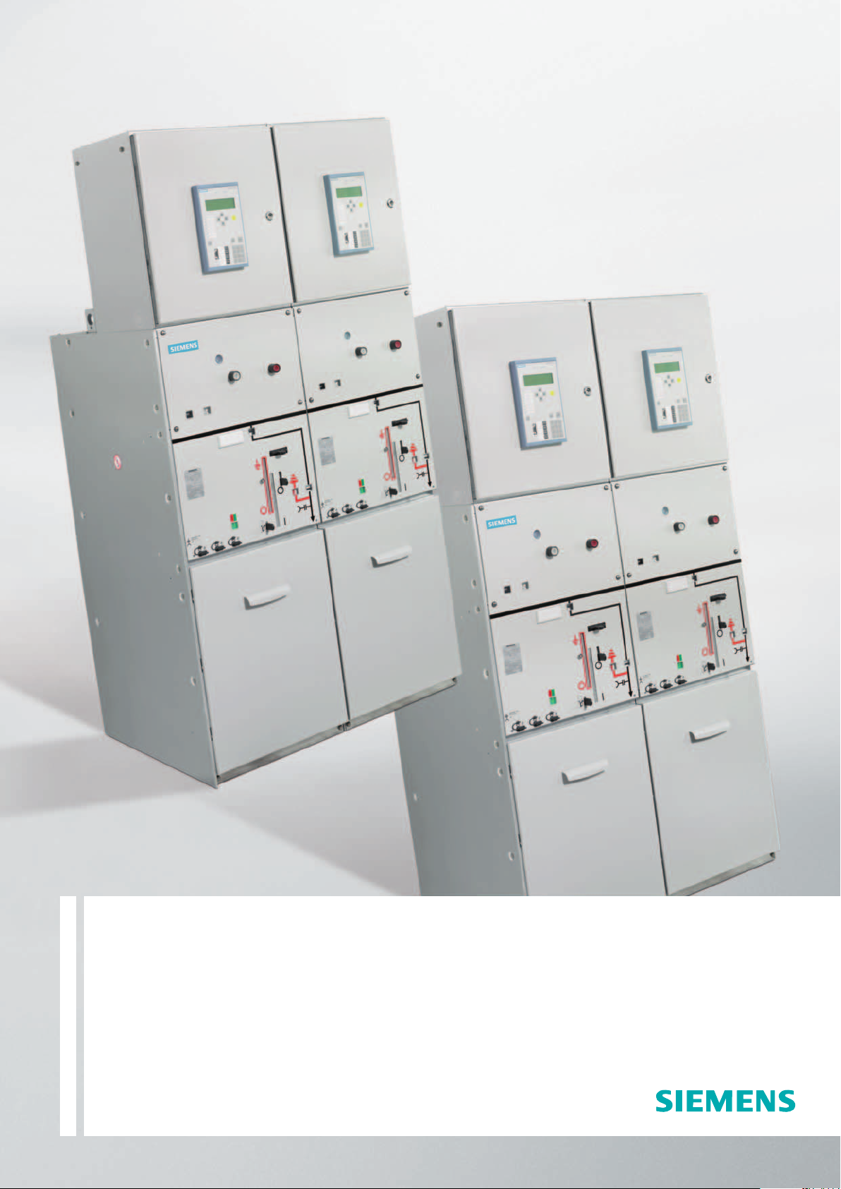
Switchgear Type 8DH10
up to 24 kV, Gas-Insulated, Extendable
Medium-Voltage Switchgear
Catalog HA 41.11 · 2008
Answers for energy.
Page 2

Application, RequirementsContents
Features
Application, Requirements Page
Features, typical uses 2 and 3
Technical Data
Electrical data, filling pressure,
temperature 4 and 5
Switchgear installation, shipping data 6 and 7
Product Range
Product range overview 8 to 15
Design
Panel design 16 and 17
Components
3AH vacuum circuit-breaker 18 and 19
Three-position switch-disconnector 20
Busbars 21
Transformers 22 to 27
Cable connection 28
Low-voltage equipment 29
Dimensions
Individual panels, panel blocks 30 to 34
Metering panel combinations 33 and 35
Floor openings and fixing points 36 to 39
Cable connection examples 40
Standards, Transport, Notes
Standards, specifications, guidelines 41
Trans po rt data, classification 42
Notes 43
For further information, please refer to
•
Catalog HA 40.1: (Switchgear Type 8DJ and 8DH,
General Part)
•
Supplements to Catalogs HA 45.31/41.11
The products and systems described in this catalog are
manufactured and sold according to certified quality and
enviromental management system (acc. ISO 9001 and
ISO 14001).
(DQS Certificate Reg. No. DQS 003473 QM UM).
The certificate is accepted in all IQNet countries.
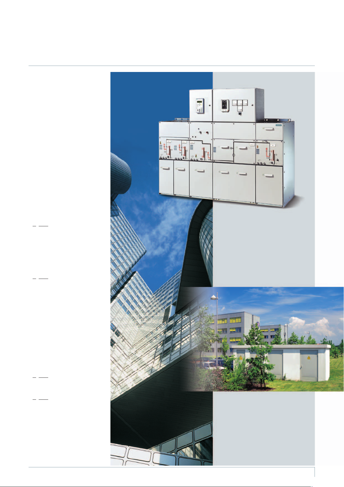
8DH10 switchgear is a factoryassembled, type-tested, three-pole,
metal-enclosed, metal-clad singlebusbar switchgear for in-door in
-
stallation:
Up to 24 kV
•
Feeder currents up to 630 A
•
Busbar currents up to 1250 A
•
Typ ical us es
8DH10 switchgear is used – even
under severe envir onmental conditions – for power distribution in
secondary distribution systems,
such as
Substations, customer transfer
n
substations, distribution substations and switching substa
tions of power supply and
public utilities
Industrial plants, such as:
n
Wind power stations
•
High-rise buildings
•
Airports
•
Lignite open-cast mines
•
Underground railway stations
•
•
Sewage treatment plants
•
Port facilities
•
Traction power supply systems
•
Automobile industry
•
Petroleum industry
•
Chemical industry
•
Cement industry
•
Unit-type heating power stations
•
Textile, paper and food
industry
•
Emergency power supply
installations
Modular design
•
Individual panels and panel
blocks can be freely combined
andextended–without
gas work
on site
•
Low-voltage compartments can
be supplied in two overall heights
and are wired to the panel by
means of plug-in connections
Reliability
•
Type and routine-tested
•
Standardized and manufactured
using numerically controlled
machines
•
More than 500,000 8DJ/8DH
panels in operation worldwide
for many years
Quality and environment
Quality and environmental
management system acc. to
DIN EN ISO 9001 and
DIN EN ISO 14001
Personal safety
Safe-to-touch and hermetically
•
sealed primary enclosure
HV HRC fuses and cable sealing
•
ends are only accessible when
outgoing feeders are earthed
Operation only possible when
•
enclosure is closed
Logical mechanical interlocking
•
Capacitive voltage detecting sys
•
tem to verify saf e isolation from
supply
Feeder earthing by means of
•
make-proof earthing switches
Security of operation
Hermetically sealed primary
•
enclosure independent of
environmental effects (such as
pollution, humidity and small animals) – sealed for life:
– Welded switchgear vessel
– Welded-in bushings and operating
mechanism
•
Operating mechanism parts
maintenance-free
(IEC 62271-1 / VDE 0671-1)
•
Operating mechanisms of switch
ing devices located outside the
switchgear vessel (primary enclo
sure)
•
Switchgear interlocking system
with logical mechanical interlocks
•
Mechanical switch-position
indicators integrated in the
mimic diagram
Cost-efficien c y
Extremely low “life-cycle costs”
throughout the entire product
service life as a result of:
•
Maintenance-free concept
•
Climatic independence
•
Minimum space requirements
•
Maximum availability
Security of investment
Innovative developments, such as:
•
Modular design
•
Switchgear extension without gas
work on site
•
Maintenance-free 3AH vacuum
circuit-breaker
•
SIPROTEC protection device family
-
-
© Siemens AG 2008
2
Switchgear Type 8DH10, up to 24 kV, Gas-Insulated, Extendable Siemens HA 41.11 2008
Page 3
Technology
Maintenance-free
•
Climate-independent
•
Partition class: Class PM
•
(metallic partition)
Three-pole primary enclosur e,
•
metal-enclosed
Insulating gas SF
•
Welded switchgear vessel without
•
6
seals, made of stainless steel,
with welded-in bushings for elec
trical connections and mechanical
components
Three-position switch-discon-
•
nector with load-break and
make-proof earthing function
Cable connection for bushings
•
with outside cone
Connection with cable plugs
•
– In ring-main feeders and
circuit-br eaker feeders with
bolted contact (M16)
– In transformer feeders with
plug-in contact
Option: Connection with conven-
•
tional cable sealing ends
– For thermoplastic-insulated
cables via elbow adapter
AKE 20 / 630 (make Siemens)
– For paper-insulated mass-
impregnated cables via commercially available adapter systems
•
Easy installation
•
Option: Pressure absorber system
– Maintenance-fr ee
– For rated short-time withstand
current I
£ 20 kA
k
– For single and multi-panel
combinations of 700 mm to
2000 mm width (for panel type
ME1 with max. 1 adjacent panel)
– With 300 mm high pressure ab-
sorber duct below the switchgear
and
– With 115 mm deep pressure
absorber duct for pressure relief
upwards
–Withscrewed-oncable
compartment cover
– Possible for switchgear with stand -
ard cable compartment cover
ption: Deeper cable compart-
O
ment cover: 105 or 300 mm
– For overall height of switchgear,
seepage6
ption: Free-standing arrange-
–O
ment, for overall height of
switchgear 2300 mm and with
rear cover
For further information concerning
thepressureabsorbersystem,
please refer to page 39
and to Catalog HA 40.1
Standards
Seepage41
Application
T ypical uses
s
p
e
a
3
1
0
1
4
A
-
s
p
e
4
1
0
1
4
A
H
R
H
R
Example
Customer transfer switchgear
s
p
e
5
1
0
1
4
A
H
R
Application
Customer transfer substation in an
accessible switchgear building
(transformers, medium-voltage and
low-voltage in a factory-assembled
building)
Application
Power supply of high-rise buildings
Switchgear Type 8DH10, up to 24 kV, Gas-Insulated, Extendable Siemens HA 41.11 2008
3
Page 4
Technical Data
Electrical data
Common
electrical data
Filling pressure,
temperature,
partition class
and
classification
Panel data
Ring-main panel
type RK,
bus sectionalizer
panel type LT2,
cable panel
type K
Rated insulation level Rated voltage U
Rated short-dur. power-freq. withstand voltage U
– phase-to-phase, phase-to-earth, open contact gap kV
– across the isolating distance kV2023
Rated lightning impulse withstand voltage U
– phase-to-phase, phase-to-earth, open contact gap kV
– across the isolating distance kV6070
Rated frequency f
Rated normal current I
r
2)
r
for busbar (standard) up to A 630 630 630 630 630
forbusbar(option)
Rated filling level p
Min. functional level p
re
me
Ambient air temperature T
for insulation 150 kPa (absolute) at 20 °C
for insulation 130 kPa (absolute) at 20 °C
3)
Panels without secondary equipment Class “Minus 25 indoor” (-25 to +70 °C4))
Panels with secondary equipment, Class
r
)
*
kV 7.2121517.5B)24
:
d
:
p
1)
28
1)
32
1)
75
1)
85
50/60 Hz
A 1250 1250 1250 1250 1250
“Minus 5 indoor” (-5 to +55 °C
circuit-breaker panels
Partition class Class PM (metallic partition)
Loss of service
continuity category
Rated normal current I
5)
2)
r
Rated short-time
withstand current I
k
Rated peak withstand current I
Rated short-circuit making current I
LSC (loss of service continuity) LSC 2
for feeder (for panel types RK ... and K ...) A 400, 630 400, 630 400, 630 400, 630 400, 630
for bus sectionalizer panel type LT2 A
400, 630 400, 630 400, 630 400, 630 400, 630
for switchgear with tk= 1 s up to kA 20 25 20 25 20 25 20 25 20
for switchgear with t
p
ma
= 3 s (option) up to kA – – 20 – 20 – 20 – 20
k
up to kA 50 63 50 63 50 63 50 63 50
up to kA 50 63 50 63 50 63 50 63 50
36
39
95
110
B)
38
45
95
110
4)
)
50
60
125
145
Transformer
panel type TR
Rated normal current I
Rated short-time
withstand current I
Rated peak withstand current I
Rated short-circuit making current I
Reference dimension “e“ of the HV HRC fuse links mm 292
Circuit-breaker
Rated normal current I
panel type LS,
bus sectionalizer
type LK/LT1
Rated short-time
withstand current I
Rated peak withstand current I
Rated short-circuit making current I
Rated short-circuit breaking current I
Electrical service life of
3AH vacuum circuit-breakers
*) Not for billing metering
panels type ME1
B) Data for Russian Federation:
– Rated voltage 12 kV
– Rated Short-duration power-
frequency withstand voltage 42 kV
1) According to some national requirements, higher values of the rated
short-duration power-frequency
withstand voltage available for
=20kAwith:
I
k
- 42 kV for phase-to-phase,
phase-to-earth and open contact
gap as well as
- 48 kV across the isolating distance
2)
r
for feeder
6)
for switchgear with tk= 1 s up to kA 20 25 20 25 20 25 20 25 20
k
2)
r
for switchgear with t
6)
p
6)
ma
for feeder (for panel types LS ...) A 400, 630 400, 630 400, 630 400, 630 400, 630
for bus sectionalizer panel type LT1 A 400, 630 400, 630 400, 630 400, 630 400, 630
for switchgear with tk= 1 s up to kA 20 25 20 25 20 25 20 25 20
k
for switchgear with t
p
ma
8)
sc
at rated normal current 10 000 operating cycles
at rated short-circuit breaking current 50 breaking operations
Higher values of the rated lighting
impulse withstand voltage
=20kA):
(for I
k
- 95 kV for phase-to-phase,
phase-to-earth and open contact
gap as well as
- 110 kV across the isolating
distance
2) The rated normal currents apply
to ambient air temperatures of
max. 40 °C. The 24-hour mean
value is max. 35 °C (according to
IEC 62271-1 / VDE 0671-1)
A 200 200 200 200 200
= 3 s up to kA – – 20 – 20 – 20 – 20
k
up to kA 50 63 50 63 50 63 50 63 50
up to kA 25 25 25 25 25 25 25 25 25
7)
292 442 442 442
= 3 s up to kA – – 20 – 20 – 20 – 20
k
up to kA 50 63 50 63 50 63 50 63 50
up to kA 50 63 50 63 50 63 50 63 50
up to kA 20 25 20 25 20 25 20 25 20
3) Operating conditions according to
IEC 62271-200.
For application, see also pages
2 and 41 (climate and ambient
conditions)
4) Temperature range, reduced
normal currents at ambient air
temperatures > +40 °C
6) Depending on the HV HRC fuse link,
observe the max. let-through
current of the HV HRC fuse links
7) Extension tube (150 mm long)
required additionally for fuse
mounting 442 mm
8) For the 3AH vacuum cir cuit-breaker
5) Classification accordin gto
IEC 62271-200 (see also page 42)
4
Switchgear Type 8DH10, up to 24 kV, Gas-Insulated, Extendable Siemens HA 41.11 2008
Page 5
Technical Data
Electrical data
Common
electrical data
Filling pressure,
temperature,
partition class
and
classification
Panel data
Busbar earthing
panel
type SE,
busbar voltag e
metering panel
type MS1V/ME3
Rated insulation level Rated voltage U
Rated short-dur. power-freq. withstand voltage U
– phase-to-phase, phase-to-earth, open contact gap kV
– across the isolating distance kV2023
Rated lightning impulse withstand voltage U
– phase-to-phase, phase-to-earth, open contact gap kV
– across the isolating distance kV6070
Rated freque n cyf
Rated normal current I
r
2)
r
for busbar (standard) up to A 630 630 630 630 630
forbusbar(option)
Rated filling level p
Min. functional level p
re
me
Ambient air temperature T
for insulation 150 kPa (absolute) at 20 °C
for insulation 130 kPa (absolute) at 20 °C
3)
Panels without secondary equipment Class “Minus 25 indoor” (-25 to +70 °C4))
Panels with secondary equipment, Class
r
)
*
kV 7.2121517.5B)24
:
d
:
p
1)
28
1)
32
1)
75
1)
85
50/60 Hz
A 1250 1250 1250 1250 1250
“Minus 5 indoor” (-5 to +55 °C
circuit-breaker panels
Partition class Class PM (metallic partition)
Loss of service
continuity category
5)
Rated short-time
withstand current I
k
Rated peak withstand current I
Rated short-circuit making curr e n tI
LSC (loss of service continuity) LSC 2
for switchgear with tk= 1 s up to kA 20 25 20 25 20 25 20 25 20
for switchgear with t
p
ma
=3s(option) uptokA
k
up to kA 50 63 50 63 50 63 50 63 50
up to kA 50 63 50 63 50 63 50 63 50
– – 20 – 20 – 20 – 20
36
39
95
110
B)
38
45
95
110
4)
)
50
60
125
145
Billing metering
Rated normal current I
panels
types ME1
and ME2
Rated short-time
withstand current I
Rated peak withstand current I
*) Not for billing metering
panels type ME1
B) Data for Russian Federation:
– Rated voltage 12 kV
– Rated Short-duration power-
frequency withstand voltage 42 kV
1) According to some national requirements, higher values of the rated
short-duration power-frequency
withstand voltage available for
=20kAwith:
I
k
- 42 kV for phase-to-phase,
phase-to-earth and open contact
gap as well as
- 48 kV across the isolating distance
2)
r
for transfer up to A 630 630 630 630 630
for fee de r(T with cable pane lastype ME1-K) up to A 630 630 630 630 630
for busbar metering up to A 630 630 630 630 630
for switchgear with tk=1s uptokA– 2520 2520 2520 2520
k
for switchgear with t
p
Higher values of the rated lighting
impulse withstand voltage
=20kA):
(for I
k
- 95 kV for phase-to-phase,
phase-to-earth and open contact
gap as well as
- 110 kV across the isolating
distance
2) The rated normal currents apply
to ambient air temperatures of
max. 40 °C. The 24-hour mean
value is max. 35 °C (according to
IEC 62271-1 / VDE 0671-1)
= 3 s up to kA 20 – 20 – 20 – 20 – 20
k
up to kA 50 63 50 63 50 63 50 63 50
3) Operating conditions according to
IEC 62271-200.
For application, see also pages
2 and 41 (climate and ambient
conditions)
4) Temperature range, reduced
normal currents at ambient air
temperatures > +40 °C
5) Classification accordin gto
IEC 62271-200 (see also page 42)
Switchgear Type 8DH10, up to 24 kV, Gas-Insulated, Extendable Siemens HA 41.11 2008
5
Page 6
HA41-2286g eps
³1000775
³10001070
>600
2000
10
³50
³15
10
³50
³1000
³2400
**
7
20
3
4
5
6
7
8
9
11
2
12
1
18
13
19
22
10
14
2300
*
*
***
HA41-2287h eps
115
300
³15
890
828
834
³2400
**
³1000
~
200
15
16
17
15
13
21
21
22
23
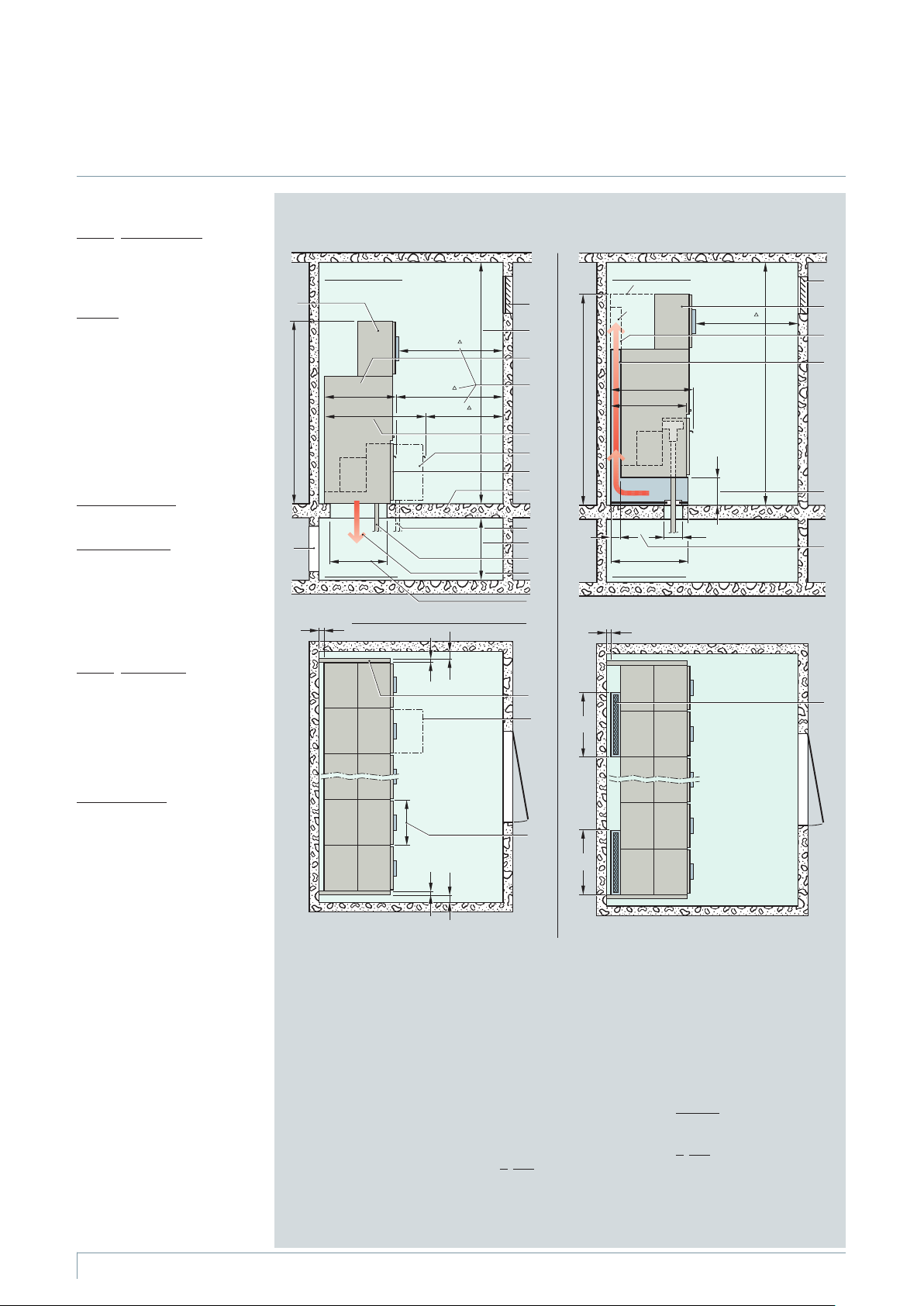
Technical Data
Switchgear installation
Room planning
Switch
gear installation
Wall-standing arrangement
– Single row
– Double row (for face-to-face
arrangement)
Free-standin g
Option:
arrangement
For room planning and
switchgear installation, please
note:
– Floor openings: Dimensions
see pages 36 to 39
– Direction of pressure relief
acc. to serial no. 13
– Respectiv e pressure relief
rooms
Room dimensions
see opposite
dimension drawings
Door dimensions
The door dimensions depend
on the
–Numberofpanelsina
transport unit
– Design with or without
low-voltage compartment
Switchgear installation with
standard panels
Switchgear room
Cable basement
Side view
Switchgear installation with rear-side
pressure absorber duct (option)
Switchgear room
Cable basement
Side view
gear fastening
Switch
•
For floor openings and fixing
points of the switchgear,
see pages 36 to 39
•
Foundations:
– Steel structure
– Steel-reinforced concrete
Panel dimensions
Weight
For details, please refer to page 7.
* Switchgear height for version with
pressure absorber duct:
** Installation conditions for internal
– For wall-standing arrangement
W 1950 mm (panel combination
without metering panel ME1)
W 2300 mm (for combination
with metering panel ME1)
– For free-standing arrangement
W 2300 mm (high end walls, rear
wall and front covers, optional
low-voltage compartment)
arc classification acc. to
IEC 62271-200
*** Height of pressure absorber duct
2100 mm with:
– Wall-standing arrangement with
metering panel ME1
– Free-standing arrangement for all
panel types
B Depending on national
specifications:
– For extension/panel replacement:
Control aisle W 1000 mm
recommended (for Germany
W 800 mm)
6
Switchgear Type 8DH10, up to 24 kV, Gas-Insulated, Extendable Siemens HA 41.11 2008
see p. 30 to 34
Top v iew Top v iew
1 Relief opening
2 Opening (e.g. for ventilation
as option)
3 Room height
4 Panel depth of the standard
panel (may be 15 mm deeper
for free-standing arrangement,
depending on the panel design)
5 Control aisle
6 Panel depth of panels with
deep cable compartment
cover
7 Deep cable compartment
cover
8 S tandar d cable compartment
cover
B
9 Foundation
nd
10 2
cable for connection with
of double T-plugs in conjunction with larger floor opening
and design with deep cable
compartment cover
11 Height of the cable
basement corresponding to
the cable bending radius
12 Cable
13 Direction of pressure relief
14 Floor openings:
Dimensions see pages 34 to 37
ption:
15 O
Pressure absorber duct
16 Base height of the pressure
absorber duct beneath the
panel
17 Depth of the pressure absorber
duct behind the panel
18 Wall distance
19 End wall
20 Panel width
21 Width of the pressure absorber duct
– 700 mm for panel combinations
– Approx. 850 mm for metering
panels type ME1
22 Standard:
Low-voltage compartment
for circuit-breaker panels
ption:
O
–Low-voltagecompartment
forallotherpaneltypesor
–Frontcover
23 Relief outlet
Page 7
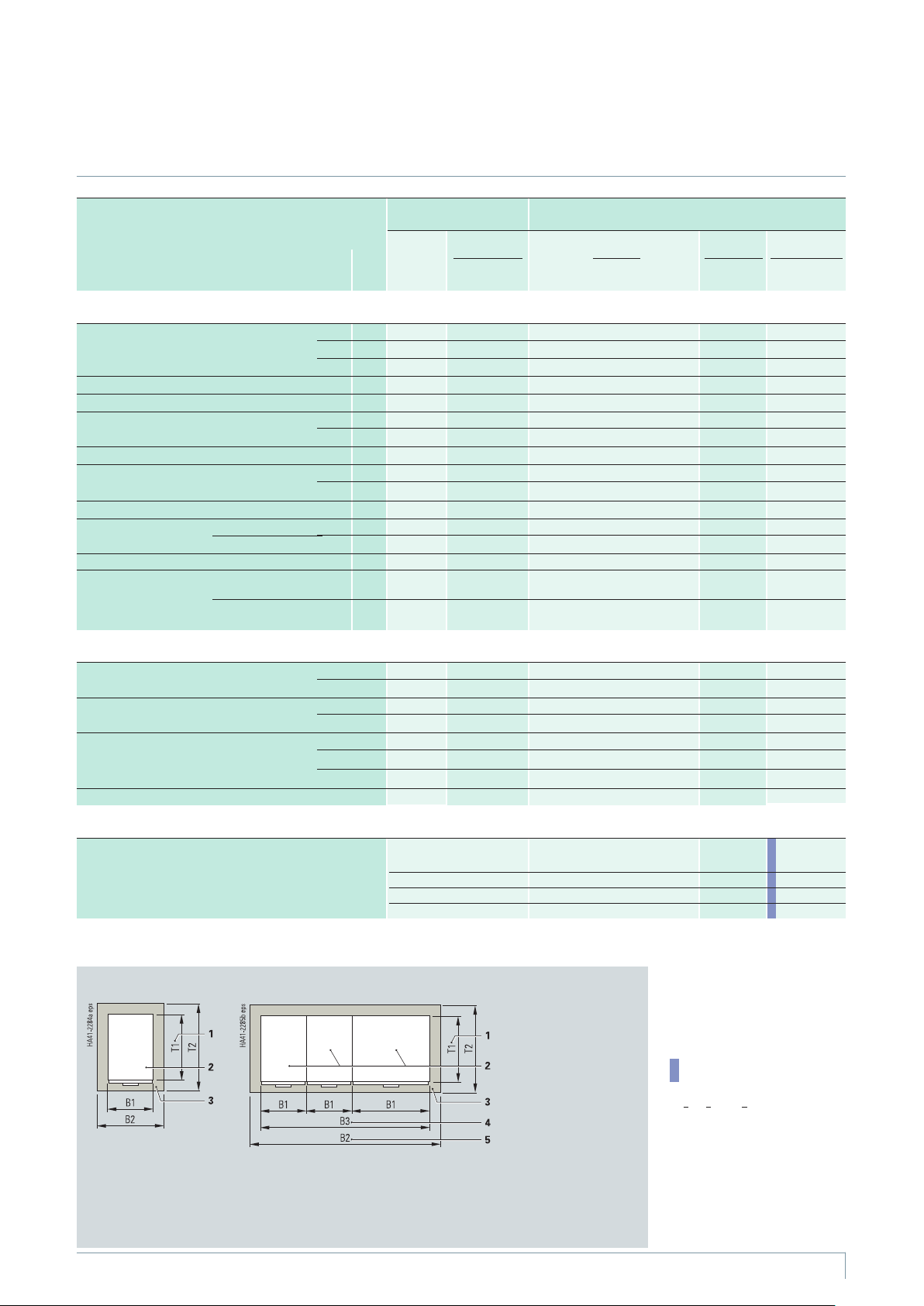
Technical Data
Shipping data
Individual panel, panel block
or combinations thereof
for standard switchgear
(without pressure relief duct)
Transport of individual panels
Ring-main panel (standard)
Cable panel (standard)
Transformer panel
Circuit-breaker panel (standard)
Circuit-breaker panel
Bus sectionalizer panel with circuit-breaker
Bus sectionalizer panel with switch-disconnector LT2 LT
Busbar earthing panel
Busbar voltage metering panel ME3 MS1 V 500 250 / 310 0.70 1.60 / 2.20 1.10 1.23 / 1.69 310 / 370
Billing metering with cast-resin
panels, insulated transformers
air-insulated **
Transport of panel blocks
Ring-main panel block
Transformer panel block
Ring-main/transformer panel block
Cable connection/transformer panel block KT-B2 700 300 / 420 1.08 1.60 / 2.20 1.10 1.90 / 2.61 360 / 480
BB
with voltage transformer
with combined
transformers
Type
Short identification
current in
RK RK
RK1 RK1
RK2 RK1 V 500 200 / 260 0.70 1.60 / 2.20 1.10 1.23 / 1.69 260 / 320
KK
TR TR1
LS1 LS1
LS2 LS1V
LST1 LST1
LT1 LK
LT1-V LK V
SE1 SE
SE2 SE1 V
ME1 ME1 850 250 / 310 1.08 1.60 / 2.20 1.10 1.90 / 2.61 310 / 370
ME2 ME2 600 390 / 450 1.08 1.60 / 2.20 1.10 1.90 / 2.61 450 / 510
R-B2
R-B3
T-B2
T-B3
RT-B2
2RT-B3
3RT-B4
Panel or panel combination Transport unit (including packing) for standard panels (without
B
Width B1mmNet weight
future
350
500
350 145 / 205 0.70 1.60 / 2.20 1.10 1.23 / 1.69 205 / 265
500 180 / 240 0.70 1.60 / 2.20 1.10 1.23 / 1.69 240 / 300
500
500
500 280 / 340 0.70 1.60 / 2.20 1.10 1.23 / 1.69 320 / 380
500
500
500 150 / 210 0.70 1.60 / 2.20 1.10 1.23 / 1.69 210 / 270
350
500
700
1050
1000
1500
700
1050
1400
approx. kg
without / with
*/LVC*
LVC
150 / 210
180 / 240
– / 260
– / 380
– / 280
– / 380
150 / 210
250 / 310
280 / 400
400 / 580
320 / 440
480 / 660
300 / 420
450 / 630
580 / 820
pressure absorber system)
1)
Width B2mHeight
0.70
0.70
0.70
0.70
0.70
0.70
0.70
0.70
1.08
1.40
1.40
2.03
1.08
1.40
2.03
m
without /with
*/LVC*
LVC
1.60 / 2.20
1.60 / 2.20
– / 2.20
– / 2.20
– / 2.20
– / 2.20
1.60 / 2.20
1.60 / 2.20
1.60 / 2.20
1.60 / 2.20
1.60 / 2.20
1.60 / 2.20
1.60 / 2.20
1.60 / 2.20
1.60 / 2.20
Depth
T2 m
1.10
1.10
1.10
1.10
1.10
1.10
1.10
1.10
1.10
1.10
1.10
1.10
1.10
1.10
1.10
Volume
3
m
without /with
*/LVC*
LVC
1.23 / 1.69
1.23 / 1.69
– / 1.69
– / 1.69
– / 1.69
– / 1.69
1.23 / 1.69
1.23 / 1.69
1.90 / 2.61
2.46 / 3.40
2.46 / 3.40
3.57 / 4.91
1.90 / 2.61
2.46 / 3.40
3.57 / 4.91
Gross weight
approx. kg
without /with
*/LVC*
LVC
210 / 270
240 / 300
– / 320
– / 440
– / 340
– / 440
210 / 270
310 / 370
340 / 460
470 / 650
390 / 510
560 / 740
360 / 480
520 / 700
660 / 900
1)
Transport of combinations of different individual panels or panel blocks
Comprising
– a number of individual panels or
–1panelblockor
– a number of panel blocks or
– individual panels with panel blocks
B Short identifications of the panels have been harmonized
BB Panel type LST1: Please refer to separate Catalog HA 45.31/41.11, Supplements to Catalogs HA 45.31/41.11
Transport units for shipping (top view)
With individual panel
or panel block
With combinations of different individual
panels and/or panel blocks
(option: Panels bolted together and busbars mounted)
Overall width B3
£ 850 mm
£ 1200 mm 1.40 1.60 / 2.20 1.10 2.46 / 3.392)+70***
£ 1800 mm 2.03 1.60 / 2.20 1.10 3.57 / 4.912)+85***
£ 2350 mm 2.53 1.60 / 2.20 1.10 4.49 / 6.172)+100***
B2
1.08 1.60 / 2.20T21.10 1.90 / 2.61
1 T1 = Depth of individual
panel or of panel block
2 Individual panel or panel
block, dimension B1 x T1
3 Transport unit,
dimension B2 x T2
4 B3 = Overall width of
combination of different
individual panels
or panel blocks
5 B2 = Width of the
transport unit
Switchgear Type 8DH10, up to 24 kV, Gas-Insulated, Extendable Siemens HA 41.11 2008
2)
+60***
1) The net weight and the gross
weight depend on the extent to
which they are equipped (e.g. with
current transformers, motor operating mechanism, deep cable
compartment cover) and are
therefore given as mean value
2) Sum of the net weights of indi-
vidual panels and / or panel blocks
* Low-voltage compartment,
600 mm high, weight approx.
60 kg depending on the panel
type and on the extent
to which it is equipped
** The weights depend on the
weights of the mounted
transformers
*** Packing weight
7
Page 8

Product Range
Product range overview
Designation of the
individual panels
and panel blocks
Individual panels
Ring-main panel 350 RK RK
Cable panel without earthing switch 350 K K
Cable panel with make-proof earthing switch 350 K K
Transformer panel 500 TR TR1
Transformer panel with plug-in voltage transformers 500 TR-V TR1-V
Circuit-breaker panel 500 LS1 LS1
Circuit-breaker panel with plug-in busbar voltage transformers 500 LS2 LS1 V
Circuit-breaker panel (with disconnecting circuit-breaker)
Bus sectionalizer (with vacuum circuit-breaker) 500 LT1 LK
Bus sectionalizer (with switch-disconnector)
Busbar earthing panel 350 SE1 SE
Busbar voltage metering panel 500 ME3 MS1 V
BB
Panel
width
Type
Short identifications *
current in future
Column no.
500 RK1 RK1
500 RK2 RK1V
350 RK-U RK-U
500 RK1-U RK1-U
500 RK2-U RK1V-U
350 K-U K-U
350 K-U K-U
500 TR-U TR1-U
500 TR/V TR1/V
500 LS1-U LS1-U
500 LS2-U LS1 V-U
500 LST1 LST1
500 LT1-V LK V
500 LT2 LT
500 SE2 SE1 V
Billing metering panel 850 ME1 ME1
Legend for pages 8 and 9
* Short identifications of the panels
have been harmonized
** LVterminalsasanoptionintheLV
compartment (compartment to be
ordered as an option)
B Three-position switch as
three-position switch-disconnector
(switch-disconnector
CLOSED-OPEN-EARTHED)
BB Three-position switch as
three-position circuit-breaker
(disconnecting circuit-break er
CLOSED-OPEN-EARTHED), see
Supplements to Catalogs
HA 45.31/41.11-2007
1) The equipment applies to the entire
panel block, but it is located in the
first feeder panel from the left
2) Low-voltage terminals arranged in
thelow-voltagenicheofthe
ring-main or cable feeder
8
Switchgear Type 8DH10, up to 24 kV, Gas-Insulated, Extendable Siemens HA 41.11 2008
Billing metering panel for busbar connection 850 ME1-S ME1-S
Billing metering panel with combined transformers
Panel blocks
Ring-main panel block 700 R-B2
Transformer panel block 1000 T-B2
Ring-main/transformer panel block
Cable connection/transformer panel block
(cable panel without make-proof earthing switch)
Cable connection/transformer panel block
(cable panel with make-proof earthing switch)
850 ME1-K ME1-K
cable connection 850 ME1-KS ME1-K
600 ME2 ME2
Column no.
1050 R-B3
1500 T-B3
700 RT-B2
1050 2RT-B3
1400 3RT-B4
700 KT-B2
700 KT-B2
RK
T
RK
T
RK
T
K
T
K
T
Page 9
Product Range
Equipment features
• Basic equipment
Additional equipment
°
(option), further additional
equipment on request
– Not available
Low-voltage niche as terminal comp. above the operating mechanism box
C-rail as cable bracket
Manual operating mechanism for three-position switch
Manual operating mechanism for three-position circuit-breaker
1234 567 891011 12 1314 15161718192021222324
–
•
–
•
–
•
–
•
–
•
–
•
–––
–––•–
–
•
–
•
–
•
–
•
–
•
–
•
–
•
–
•
–
•
–
•
–
••–•••
––•––––
•
––•––––
•
––•–
•
–
•
–
•
––•–
•
–––•–––•––– – – – – –––––
–––
–––•–––•––– – – – – –––––
–––
–––•––––––– – – – – –––––
1234 567 891011 12 1314 15161718192021222324
–
•
–
•
–
•
–
•
–
•
–
•
–
•
–
•
–
•
–
•
–––
–––
•
–
•
–
•
Cable compartment cover locked in place/screwed on
Interlock for cable compartment cover
–
•
•
•
•
•
•
•
•
•
•
•
•
•
•
•
•
•
•
•
•
•
•
•
•
•
•
•
•
•
•
••
–
••
–
••
––•–––
––•–––
––•–––
•••
–
––•–––
–
–––•–
–
–––•–
–
–––––
–
–––––
––•–––
––•–––
••
••
–
–
–
–
–
–
–
–
–
–
•••
–
–
•
••
–
•
–
•
–––
•
–––
•
•
•
––•––– – – – – –––––
––•––– – – – – –––––
••
••
–––
•
–––
•
••
2)
•
••
2)
•
••
2)
•
2)
•
••
2)
•
B)
Separate low-voltage niche as terminal compartment
Low-voltage terminals in the operating mechanism box **
–––
–––
–––
–––
–––
–––
–
•
–
•
–
–––
–––
–––
–––
–––
––
–––
––
–––
––
–––
––
–––•
––
BB)
OPEN: 2NO + 2NC, EARTHING CLOSED/OPEN: 2NO + 2NC; circuit-breaker
Release as shunt release for three-position switch
°
°
°
°
°
°
°
°
°
°
°
°
°
°
°
°
°
°
Signalling switch (1 NO) for remote electrical ready-for-service indication
Mechan. ready-for-servi ce indicator(e.g.for switching devices)
•
°°°
•
°°°
•
°°°
•
°°°
•
°°°
•
°°°
•
°
•
°
•
°°
•
°°
•
°°°
•
°°°
•
°°°
•
°°°
•
°°°°
•
°°°°
•
°°°°
•
°°°°
•
°
•
°°°°
•
°°°°
•
°°°
•
°°
•
°°
•
°°°
1)
1)
•
°
1)
1)
•
°
1)
1)
•
°
1)
1)
•
°
1)
1)
•
°
1)
1)
1)
1)
•
°
1)
1)
1)
1)
•
°
1)
1)
1)
1)
•
°
1)
1)
1)
1)
°
1) 1)
type LST CLOSED/OPEN:2NO + 2NC, EARTHING CLOSED/OPEN:2NO + 2NC
Aux. switch for three-position switch
––––––°––
– – – – –––––
•
Motor-operat. mechan. f. three-pos. switch
–– ––
–– ––°–––
°
–– ––•–––
–– ––•–––
°°
°°
°°
°°
°°
°°
°°
°°
°°
°°
––––––°––
°°
–– ––
°
°°
BB)
and
B)
: Switch-disconnector CLOSED/
BB)
and
B)
vacuum circuit-breaker
De-earthing lock-out for make-proof earthing switch
Interlock in circuit-breaker panel between three-position switch
––
––
––
––
––
––
–
–
–
–
–
–––•–––
–––°–––
–––
–––
–
–
––
–
––
–
––
–
–
–
of three-position switch
Closing lock-out for three-position switch
°°°
°°°
°°°
°°
°°
°°°
–
°
–
°
–
°
–
°
–
°°°°°
–
°°–°°
–
°°°°°
–
°°–°°
° °°°–°°°°°
––•–
––•–
–
°
–
°
°°°
–
°
°°°
–
°
°°°
–
°
–
°
–
°
(f. CLOSED and OPEN)
BB)
and
B)
BB)
and
B)
Locking device for three-position switch
°°
°
°
°
°
Motor operating mechanism for 3AH vacuum circuit-breaker
Short-circuit or earth-fault indicator
––
––
––
–––
–––
––
––
–––
–––
–––
–––
°°
°°
°°
°°
°
°
°
°
°
°
°°
°
––
––
–––
–––
––
–––
––
–––
––
–––
–––
––
–––
and
B)
BB)
BB)
and
and
B)
B)
Low-voltage compartment **
Release as current-transformer operated release
Mounted cable clamps
Low-voltage cover
°°°°
°°°°
°°°°
°°–°
°°–°
°°–°
°°°°
°°–°
°°°°
°°–°
°°°°
°°–°
°°°°
°°–°
–
•
•
•
•
•
•
°°
––
–
°°
––
––
––
°
°
°
°
°°–°
°°–°
°°–°
°°–°
°°–°
°°°°
°°–°
°°°°
°°–°
°°°°
°°°°
°°°°
°°°°
°°°°
°°°°
°°°°
°°°°
°°°°
°°°°
°°°°
°°°°
°°°°
°°°°
)
Secondary equipment
Switchgear Type 8DH10, up to 24 kV, Gas-Insulated, Extendable Siemens HA 41.11 2008
9
Page 10
HA41-2224_1d eps
HA41-2216_1d eps
HA41-2227_1d eps
HA41-2225_1d eps
HA41-2226_1d eps
HA41-2215_1d eps
HA41-2214_1e eps
**
HA41-2217_1d eps
HA41-2219_1e eps
**
HA41-2213_1d eps
HA41-2218_1d eps
HA41-2220_1d eps
HA41-2221_1d eps
HA41-2222_1d eps
HA41-2223_1d eps
Product Range
**
Ring-main, cable and transformer panels as individual panels
Ring-main panels
as feeder panels
option
option
option
option
option
option
Typ e R K
350 mm wide
1) 3)
Typ e R K1
500 mm wide
Option:
Typ e RK1 V
500 mm wide
Typ e R K *
350 mm wide
nd
for 2
cable*
Typ e R K *
350 mm wide
with plug-in
surge
arresters *
1) 2) 3)
Cable panels
as feeder panels
option
option
option
option
option
option
Typ e K
350 mm wide
Typ e K *
350 mm wide
nd
for 2
cable *
Typ e K *
350 mm wide
with plug-in
surge
arresters *
Transformer panels
as feeder panels
option
option
option
option
option
Typ e T R1
500 mm wide
Typ e T R1- V
500 mm wide
B
with plug-in
voltage trans
formers
Typ e T R-V
500 mm wide
-
B
(105 mm deeper
cable compartment cover)
with plug-in
voltage trans
formers instead of cable
connection
Three-position
switch-disconnector
HV HRC fuse
Capacitive
voltage detecting
system
Cable-type current
transformer
4MT8 plug-in voltage
transformer at the
cable connection
4MT8 plug-in voltage
transformer at the
connection
Cable (not
included in the
scope of supply)
2ndcable (not
included in the
scope of supply)
as transfer panels as transfer panels as transfer panels
option
Typ e R K-U
350 mm wide
for transfer
option
to the right
Option:
Typ e RK1- U
Typ e RK1V -U
500 mm wide
Typ e R K-U
350 mm wide
option
3)
2) 3)
for transfer
to the left
Option:
Typ e RK1- U
Typ e RK1V -U
500 mm wide
10
Switchgear Type 8DH10, up to 24 kV, Gas-Insulated, Extendable Siemens HA 41.11 2008
option
3)
2) 3)
Typ e K-U
350 mm wide
for transfer
to the right
Typ e K-U
350 mm wide
for transfer
to the left
option
option
Typ e T R1- U
500 mm wide
for transfer
to the right
Typ e T R1- U
500 mm wide
for transfer
to the left
Plug-in
surge arrester
Make-proof
HA41-2278e eps
earthing switch
Footnotes
seepage11
Page 11
HA41-2229_1c eps
HA41-2233_1c eps
HA41-2232_1d eps
HA41-2234_1c eps
HA41-2235_1e eps
HA41-2228_1d eps
HA41-2231_1c eps
HA41-2230_1c eps
Product Range
Ring-main, cable and transformer panels in panel blocks
BB
Ring-main panel blocks
Designs and options for each panel, see page 10
RK RK
RK
Typ e R -B2
700 mm wide
consisting of
2 ring-main panels
RK RK
Typ e R -B3
1050 mm wide
consisting of
3 ring-main panels
Transformer panel blocks
Designs and options for each panel, see page 10
TR TR
Typ e T- B2
1000 mm wide
consisting of
2 transformer panels
Ring-main/transformer panel blocks
Designs and options for each panel, see page 10
RK
RK
RK
c
TR
Typ e R T-B2
700 mm wide
consisting of
1 ring-main panel and
1 transformer panel
RK
RK RK
c
TR
Typ e 2 RT-B3
1050 mm wide
consisting of
2 ring-main panels and
1 transformer panel
c
TR
Typ e 3 RT-B4
1400 mm wide
consisting of
3 ring-main panels
and
1 transformer
panel
Three-position
switch-disconnector
HV HRC fuse
Capacitive
voltage detecting
system
BB Capacitive voltage
detecting system at
the busbar of the
panel blocks: Only
located once in the
first panelof the
block!
HA41-2278e eps
Cable (not
included in the
scope of supply)
TR
Designs
•
Busbar connection system for connection of individual
panels or panel blocks: Arranged in the left-hand panel of the
panel block (therefore extendable at a later date)
•
Only either the left-hand or the right-hand panel of the panel block
can be designed as a transfer panel with busbar connection
•
Panel blocks are also available without a busbar connection
system (extendable at a later date only via the cable feeder)
TR TR
Typ e T- B3
1500 mm wide
consisting of
3 transformer
panels
Cable connection/transformer panel block
Designs and options for each panel, see page 10
K
Designs
•
Busbar connection system for connection of individual
panels or panel blocks: Arranged in the left-hand panel of the
panel block (therefore extendable at a later date)
•
Only either the left-hand or the right-hand panel of the panel block
can be designed as a transfer panel with busbar connection
•
Panel blocks are also available without a busbar connection
system (extendable at a later date only via the cable feeder)
c
A plug-in voltage transformer cannot be provided at the connection
c
TR
Typ e K T-B 2
700 mm wide
consisting of
1 cable connection panel
1 transformer panel
Footnotes
from page 10
B Deep cable
compartment
cover required
* Depending on
the make/type of
the cable
plug or arrester:
Deep cable
compartment
cover required
** Cable-type
current transformer on the
nd
cable:
2
For 300 mm
deeper cable
compartment
cover
1) Suitable for
voltage
transformer
type 4MT8
2) Suitable for
voltage
transformer
type 4MT3
3) Suitable for
three-phase
current transformers
Switchgear Type 8DH10, up to 24 kV, Gas-Insulated, Extendable Siemens HA 41.11 2008
11
Page 12
HA41-2247_1d eps
1
)
HA41-2241_1d eps
1
)
HA41-2246_1d eps
1
)
HA41-2240_1d eps
1
)
HA41-2245_1d eps
1
)
2
)
HA41-2243 _1d eps
1
)
2
)
HA41-2239_1d eps
1
)
2
)
HA41-2237_1d eps
1
)
2
)
HA41-2244_1e eps
**
1
)
2
)
HA41-2242_1e eps
1
)
2
)
HA41-2238_1e eps
**
1
)
2
)
HA41-2236_1e eps
1
)
2
)
Product Range
2
)
1
)
Circuit-breaker panels as individual panels
BB
Circuit-breaker panels
Circuit-breaker panels with plug-in
busbar voltage transformers
as feeder panels
option
option
option option option option
Typ e L S1
500 mm wide
Basic panel
option
option
option option
option
option
option
option
Typ e L S1
*
500 mm wide
nd
for 2
cable *
as feeder panels
option
option
Typ e L S 1V/LS2
500 mm wide
Basic panel
option
option
option option
option
option
option
option
Typ e L S2
*
500 mm wide
nd
for 2
cable *
Vacuum
circuit-breaker
Three-position
switch-disconnector
Capacitive
voltage detecting
system
4MC63... threephase current
transformer
Cable-type current
transformer
on the cable
4MT8 plug-in voltage
transformer at the
cable connection
Typ e L S1
500 mm wide
with plug-in
surge arresters or
limiters *
as transfer panels
option
option
option
option
*
Typ e L S1-U
500 mm wide
for transfer
to the right
Typ e L S1-U
500 mm wide
for transfer
to the left
B
Typ e L S1
500 mm wide
with plug-in
voltage trans
B
formers
Typ e L S 1V/LS2
500 mm wide
with plug-in
-
surge arresters
or limiters *
*
Typ e L S 1V/LS2
500 mm wide
with plug-in
voltage transformers
as transfer panels
option
Type LS1V-U/LS2-U
B
4MT3 plug-in
voltage
B
transformer
at the busbar
Cable (not
included in the
scope of supply)
500 mm wide
for transfer
option
to the right
nd
cable (not
2
included in the
scope of supply)
Plug-in
HA41-2278e eps
surge arrester
or limiter
option
Type LS1V-U/LS2-U
500 mm wide
for transfer
option
to the left
12
Switchgear Type 8DH10, up to 24 kV, Gas-Insulated, Extendable Siemens HA 41.11 2008
Footnotes
seepage13
Page 13
HA41-2253_1c eps
HA41-2250_1c eps
HA41-2249_1e eps
HA41-2254_1c eps
HA41-2252_1b eps
HA41-2248_1c eps
Product Range
Bus sectionalizer with circuit-breaker , bus sectionalizer with switch-disconnector,
busbar earthing panels and busbar voltage metering panel as individual panels
BB
Bus sectionalizer
with circuit-breaker
option
option
Typ e L K/ LT 1
500 mm wide
with vacuum
circuit-breaker
option
option
Busbar earthing
panels
Typ e S E
350 mm wide
Busbar voltage metering
panel
Typ e M S 1V / ME 3
500 mm wide
Vacuum
circuit-breaker
Three-position
switch-disconnector
Capacitive
voltage detecting system
Cable-type
current trans
former on the
screened busbar
Make-proof
earthing switch
4MT8 plug-in
voltage
transformer
at the connection
-
Typ e L K V/LT1- V
500 mm wide
with vacuum
circuit-breaker and
plug-in voltage
transformers
Bus sectionalizer
with switch-disconn e ctor
option
option
Typ e LT 2
500 mm wide
Typ e S E1 V/ SE2
500 mm wide
with plug-in
voltage
transformers
4MT3 plug-in
HA41-2278e eps
voltage
transformer
at the busbar
Footnotes from
page 12 and 13
B Deep cable
compartment
cover required
BB Short identi-
fications of the
panels have
been harmonized
* Depending on
the make/type of
the cable
plug or arrester:
Deep cable
compartment
cover required
** Cable-type
current transformer on the
nd
cable:
2
For 300 mm
deeper cable
compartment
Switchgear Type 8DH10, up to 24 kV, Gas-Insulated, Extendable Siemens HA 41.11 2008
13
Page 14
HA41-2259_1c eps
P2
P1
1
)
HA41-2258_1c eps
P2
P1
1
)
HA41-2262_1b eps
P2
P1
HA41-2260_1c eps
P1
P2
1
)
HA41-2261_1c eps
P1
P2
1
)
HA41-2263_1b eps
P2
P1
HA41-2264_1b eps
P1
P2
HA41-2265_1b eps
P1
P2
HA41-2267_1c eps
P2
P1
HA41-2266_1c eps
P2
P1
HA41-2436_1a eps
P1
P2
HA41-2437_1a eps
P1
P2
Product Range
Air-insulated metering panels as transfer panels
Billing metering panels
(standard)
option
Scheme 1
Typ e M E1, 850 mm wide
for transfer to the right
option
Scheme 2
Typ e M E1, 850 mm wide
for transfer to the right,
transformer terminals
interchanged
option
Billing metering panels as end
panels, for cable connection
option
Scheme 1
Typ e M E1- K, 850 mm wide
for transfer to the right
option
Scheme 2
Typ e M E1- K, 850 mm wide
for transfer to the right,
transformer terminals
interchanged
option
Billing metering panels for
busbar connection
option
Scheme 1
Typ e M E1- S, 850 mm wide
forbusbarmetering
option
Scheme 2
Typ e M E1- S, 850 mm wide
forbusbarmetering,
transformer terminals
interchanged
option
Current transformer, cast-resin
insulated
1
)
Voltage transformer,
cast-resin insulated
or on request:
Voltage transformer,
cast-resin insulated,
with HV HRC fuse
Voltage transformer, cast-resin
insulated
Fixed earthing
points for busbar
earthing
Cable (not
HA41-2278d eps
included in the
scope of supply)
P1 and P2
are terminal
designations
of the current
transformer
Scheme 3
Typ e M E1, 850 mm wide
for transfer to the right
option
option
Scheme 4
Typ e M E1, 850 mm wide
for transfer to the right,
transformer terminals
interchanged
Note
Schemes 1 to 4 also feasible
for transfer to the left
14
Switchgear Type 8DH10, up to 24 kV, Gas-Insulated, Extendable Siemens HA 41.11 2008
Note
Schemes 1 to 4 also feasible
for transfer to the left
Scheme 3
Typ e M E1- K, 850 mm wide
for transfer to the right
Scheme 4
Typ e M E1- K, 850 mm wide
for transfer to the right,
transformer terminals
interchanged
Scheme 3
Typ e M E1- S, 850 mm wide
for busbar metering,
transformer terminals
interchanged
option
Scheme 4
Typ e M E1- S, 850 mm wide
for busbar metering,
transformer terminals
interchanged
Page 15

HA41-2268_1e eps
P2
P1
1
)
HA41-2269_1e eps
P2
P1
1
)
HA41-2270_1e eps
P1
P2
1
)
HA41-2271_1e eps
P1
P2
1
)
Product Range
HA41-2277_1d eps
2
)
3
)
P2
P1
HA41-2276_1d eps
P2
P1
2
)
3
)
HA41-2439_1b eps
P1
P2
2
)
3
)
HA41-2438_1b eps
P1
P2
2
)
3
)
HA41-2473a eps
P2
P1
1
)
HA41-2474a eps
P2
P1
1
)
HA41-2475a eps
P1
P2
1
)
HA41-2476a eps
P1
P2
1
)
3
)
Air-insulated metering panels as transfer panels
Billing metering panels as end
panels, for cable connection
option
Scheme 1
Typ e M E1- KS , 850 mm wide
for transfer to the right
option
Scheme 2
Typ e M E1- KS , 850 mm wide
for transfer to the right,
transformer terminals
interchanged
option
Billing metering panels
as individual panels, for cable
connection
option
Scheme 1
Type ME1-KK, 850 mm wide
for cable connection
option
Scheme 2
Type ME1-KK, 850 mm wide
for cable connection,
transformer terminals
interchanged
option
Billing metering panels *
with metal-enclosed
combined transformers
Scheme 1
Typ e M E2, 600 mm wide
for transfer to the right
Scheme 2
Typ e M E2, 600 mm wide
for transfer to the right,
transformer terminals
interchanged
Current transformer, cast-resin
insulated
1
)
Voltage transformer,
cast-resin insulated
or on request:
Voltage transformer,
cast-resin insulated,
with HV HRC fuses
4MK plug-in
combined current
transformer,
metal-enclosed
4MK plug-in
combined voltage
transformer,
metal-enclosed
Fixed earthing
points for busbar
earthing
HA41-2278e eps
Cable (not
included in the
scope of supply)
option
Note
Schemes 1 to 4 also feasible
as left-hand end panel
for transfer to the left
Scheme 3
Typ e M E1- KS , 850 mm wide
for transfer to the right
Scheme 4
Typ e M E1- KS , 850 mm wide
for transfer to the right,
transformer terminals
interchanged
option
Scheme 3
Type ME1-KK, 850 mm wide
for cable connection
Scheme 4
Type ME1-KK, 850 mm wide
for cable connection,
transformer terminals
interchanged
Scheme 3
Typ e M E2, 600 mm wide
for transfer to the left
Scheme 4
Typ e M E2, 600 mm wide
for transfer to the left,
transformer terminals
interchanged
* Mainly for connection to
bus sectionalizer with switch-disconnector
LT1, LT1 -V an d LT 2
Switchgear Type 8DH10, up to 24 kV, Gas-Insulated, Extendable Siemens HA 41.11 2008
P1 and P2
are terminal
designations
of the current
transformer
15
Page 16

HA41-2279e eps
1
2
3
4
5
6
7
8
9
10
11
12
13
14
15
16
17
18
19
20
21
22
23
2
24
15
25
26
27
28
29
61
62
HA41-2280d eps
1
3
38
5
6
7
9
10
11
12
13
14
15
16
17
18
19
20
21
22
33
32
31
34
23
35
15
36
37
27
28
29
61
62
HA41-2281e eps
1
2
11
39
6
7
41
40
42
39
2
22
61
62
30
62
62
Design
Panel design (examples)
Ring-main panel Section Transformer panel Section
Type RK Type TR
Billing metering panel, air-insulated Section
16
Switchgear Type 8DH10, up to 24 kV, Gas-Insulated, Extendable Siemens HA 41.11 2008
Type ME1
Legend for pages 16 and 17
1 O
ption: Low-voltage compartment
2 Niche for customer-side low-voltage equipment,
with hinged cover
3 Switch-position indicator for load-break
function “CLOSED – OPEN”
4 Switch-position indicator for earthing
function “OPEN – EARTHED”
5 Ready-for-service indicator
6 Rating and type plate
7 Mimic diagram
8 O
ption: Short-circuit / earth-fault indicator
9 Sockets for voltage detecting system
10 Arrangement of the busbars
11 Feeder designation label
12 O
ption: Locking device for three-position
switch-disconnector
13 Manual operation for the mechanism of
the earthing function
14 Manual operation for the mechanism of
the load-break function
15 Interlock of the cable compartment cover
16 Arrangement of the cable connections
17 Busbar system
18 Switchgear vessel filled with gas
19 Busbar connection
20 Pressure relief device
Page 17

HA41-2282e eps
51
52
12, 53
13
3
4
7
14
23
16
17
18
19
20
21
22
43
44
45
46
47
48
49
50
11
5
6
8
9
15
10
46
24
15
25
26
54
27
28
29
55
61
63
62
HA41-2283c eps
58
59
60
57
56
61
Circuit-breaker panel Section
Type LS1 (without voltage transformers)
Type LS2-V (with voltage transformers)
Design
Panel design (examples)
21 Partition for busbar
22 Earthing busbar with earthing connection
23 Three-position switch-disconnector
24 Spring-operated mechanism
25 Bushing for cable plug with bolted contact (M16)
26 O
ption: Cable T-plug
27 Cable compartment cover
28 Cable compartment
29 Cable bracket
30 Earthing connection for earthing accessories
31 HV HRC fuse assembly, cover removed
32 Handle for replacing HV HRC fuse links
33 Interlock for HV HRC fuse assembly
34 Cover of the HV HRC fuse compartment
35 Spring-operate d / stored-energy mechanism
36 Bushing for cable plug with plug-in contact
37 Cable elbow plug with plug-in contact
38 Switch-position indicator for load-break function
“CLOSED – OPEN” and, if applicable,
“HV HRC fuse tripped” or “shunt release tripped”
39 Cover for access to the busbar connection and to
the instrument transformers, screwed on
40 4MR voltage transformer
41 4MA7 current transformer
42 Covertobusbarconnection
compartment, scre wed on
43 O
ption: SIPROTEC bay control unit
44 Low-voltage compartment (standard)
Vacuum circuit-breaker:
45 Opening for the hand crank
– for closing with manual operating mechanism
– for emergency operation with motor operating
mechanism
46 Operating mechanism box
47 Mechanical “ON” pushbutton (not supplied with
spring-operated mechanism)
48 Mechanical “OFF” pushbutton
49 Operating cycle counte r
50 “Spring charged” indicator
51 Vacuum interrupter
52 Switch-position indicat or
53 O
ption: Interlock between vacuum circuit-breaker
and three-position switch-disconnector
ption: Three-phase current transformer
54 O
(protection transformer)
Switchgear Type 8DH10, up to 24 kV, Gas-Insulated, Extendable Siemens HA 41.11 2008
55 Cable-type current transformer
56 4MT3 plug-in voltage transformer at the busbar
57 Bushing for connection of plug-in voltage transformers
58 Plug-in connection according to EN 50 181 /
DINEN50181asinterfacetype“A”
59 O
ption: 4MT8 plug-in voltage transformer at the connection
60 Deep cable compartment cover
61 Wiring duct, removable, for control cables and/or bus wires
62 Cover screwed on
63 O
ption: Interlock be tween three-position
switch-disconnector and circuit-breaker
17
Page 18

Components
3AH vacuum circuit-breaker
Features
According to IEC 62271/
•
VDE 0671-100
(standards see page 41)
Application of all 8DH10
•
switchgear in hermetically
sealed vessel in conformity
with the system
Climate-independent vacuum
•
interrupter poles in the
gas-filled switchgear vessel
Maintenance-free for indoor
•
installation according to
IEC 62271-1/ VDE 0671-1
(standards see page 41)
Individual secondary equipment
•
A metal bellows is used for
•
gasketless separation of the
-insulation and the operat-
SF
6
ing mechanism – as already
used with success for over
100,000 vacuum interrupters
Switching duties and
operating mechanisms
The switching duties of the
vacuum circuit-breaker are dependent, among other factors, on
its type of operating mechanism.
Three operating mechanism versions are available:
•
Motor operating stored-energy
mechanism
– For auto-reclosing (K),
– For synchronization and
rapid load transfer (U)
•
Manual operating stored-
energy mechanism
– For auto-reclosing (K)
•
Manual spring-operated me-
chanism (= spring CLOSED,
stored-energy OPEN)
for auto-reclosing (K)
–Not
– For normal closing and
– For storage of one
opening
operation
Further o
perating mechanism
features
•
Located outside the switch-
Operating mechanism
functions
Motor operating mechanism
(M1 *)
Inthecaseofthemotoroperating mechanism, the closing
spring is charged by means of
a motor and latched in the
charged position (the “spring
charged” indication is visible).
Closing is effected either by
means of an ON pushbutton or
a closing solenoid. The closing
spring is recharged automati
cally (for auto-reclosing).
Manual operatin
gstored-
energy mechanism
The closing spring is charged
by means of the hand crank sup
plied until latching of the closing
latch is indicated
(= “spring charged” indication).
Subsequently the vacuum
circuit-breaker can be closed
either manually or electrically
and the closing spring can be
recharged manually. The “possibility to close” is thus stored
once more (for auto-reclosing).
Manual s
pring-operated
mechanism
(= spring CLOSED, stored-energy
OPEN)
The closing spring of the vacuum
circuit-breaker is charged by
means of the hand crank supplied until the vacuum circuitbreaker closes. Subsequently
either manual or electrical open
ing is possible.
Vacuum circuit-breakers with
spring-operated mechanism are
not suitable for auto-reclosing.
Trip-free mechanism
The vacuum circuit-breaker
is fitted with a trip-free
mechanism.
gear vessel in the operating
mechanism box and behind
the control board
•
Stored-energy spring
mechanism for 10,000
operating cycles
Abbreviations for switching
duties and applications:
U = Synchr onization and
rapidloadtransfer
(make time £ 90 ms)
K=Auto-reclosing
O = OPEN operation
For further technical data and description of typical applications,
please refer also to Catalog HG 11.11 “3AH Vacuum Circuit-Breakers”
1) Motor rating at
24 V to 220 V DC: 350 W
110 V and 230 V AC: 400 VA
2) With closing solenoid
* Item designation
CO = CLOSE operation with subsequent
OPEN operation at the short est
internal close-open time of the
vacuum circuit-breaker
t = Dead time 0.3 s
t ‘ = Dead time 3 min
1)
1
2
3
4
5
6
7
8
10
11
13
-
15
-
s
p
e
6
1
0
1
4
A
H
R
Operating mechanism of the vacuum circuit-breaker
(forthelegend,seepage19)
Differentiation features between the vacuum circuit-breakers
depending on the operating mechanism version
Operating
mechanism
version
Typical uses Utility
-
Mechanism
function
Mechanism
operation
Closing the
vacuum
circuit-breaker
Closing
solenoid, e.g.
for remote
electrical
closing
Rated
operating
sequence
Autoreclosing (K)
Motor operating
stored-energy
mechanism
substations
and industrial
plants
Stored-energy
CLOSED,
stored-energy
OPEN
1)
With motor
manual (emergency) operation at the panel
including antipumping
Electrically
mechanically at
the panel with
pushbutton
Always provided, with electrical signal
“closing spring
charged”
O-t-CO
or
O-t-CO-t’-CO
Suitable (multiple auto-reclosing possible)
,
2)
or
Manual
operating
stored-energy
mechanism
Classic transfer
substations and
substations
without auxiliary
voltage supply
Stored-energy
CLOSED,
stored-energy
OPEN
With hand
crank
Mechanically
at the panel
with pushbutton, option:
electrically
Option Without
O-t-CO O or CO
Suitable (only
with closing
solenoid)
Manual springoperated
mechanism
Simple utility
substations
(circuit-breaker
employed as
transformer
switch)
Spring
CLOSED,
stored-energy
OPEN
With hand
crank
Mechanically
at the panel
with hand
crank (charging
2)
process)
–
18
Switchgear Type 8DH10, up to 24 kV, Gas-Insulated, Extendable Siemens HA 41.11 2008
Page 19

HA41-2296b eps
9
1
3
11
17
13
5
HA41-2297a eps
8
1
2
3
4
5
6
7
10
11
12
13
14
15
16
Components
Secondary equipment of the 3AH vacuum circuit-breaker
Thescopeofthe3AHvacuum
circuit-brea ker secondary equipment depends on the type of application and offers a wide range of
options, thus allowing even the
highest requirements to be satis
fied.
Closing solenoid
Typ e 3 AY15 10 (Y9 *)
•
For electrical closing
•
Shunt releases
Typ es:
•
–Standard:3AY1510(Y1*)
ption: 3AX1101(Y2*),
–O
with energy store
Tripping by protection device or
•
electrical operation
Current-transformer
operated release
Type3AX1104(Y6*)fortrip-
•
ping pulse W 0.1 Ws in conjunction with suitable protection systems, e.g. 7SJ4 protection system, 4MC6.. transformer
protection system, SEG relay
(other designs on request)
•
Used where no external
auxiliary voltage is available,
tripping by protection device
Undervoltage release
•
Type3AX1103(Y7*)
•
Comprising:
– Energy store and unlatching
mechanism
– Electromagnetic system which is
permanently connected to voltage
while the vacuum circuit-breaker
is closed; tripping is initiated
when this voltage drops
•
Connection to voltage trans
formers possible
Anti-pumping (standard)
(mechanical and electrical)
•
Function: If constant CLOSE and
OPEN commands are present at
the vacuum circuit-breaker at
thesametime,thevacuumcir
cuit-breaker will return to the
open position after closing. It
remains in this position until a
new CLOSE command is given.
In this manner, continuous clos
ing and opening (= pumping) is
avoided.
1) For utilization
by the
customer
For further technical data and description of typical applications,
please refer also to Catalog HG 11.11 “3AH Vacuum Circuit-Breakers”
*Item
designation
Circuit-breaker tripping signal
(standard)
For electrical signalling (as pulse
•
>10ms),e.g.toremotecontrol
systems, in the case of automatic
tripping (e.g. protection)
Via limit switch (S6 *) and
•
cut-out switch (S7 *)
Varistor module
To limit overvoltages to approx.
•
500 V for protection devices
(when inductive devices are
mounted in the vacuum circuitbreaker)
For auxiliary voltages W 60 V DC
•
Auxiliary switch
Typ e 3SV 9 (S1 *)
•
Standard: 6 NO+6 NC, of which
•
2NO+2NC+2changeover
contacts are free
Option: 12 NO+12 NC, of which
•
7NO+4NC+2changeover
contacts are free
Position switch
• Type 3SE4 (S4 *)
•
For signalling “closing spring
charged”
•
Only in conjunction with storedenergy mechanisms
Mechanical interlocking
•
Dependent on the type of
operating mechanism
•
Option: Switchgear interlocking
with the three-position switchdisconnector (option: Closing
lock-out for the three-position
switch-disconnector in circuit-
-
breaker panels type LS and LT1)
•
Option: Operating mechanism
with mechanical interlocking as
– Spring-operated mechanism:
Hand crank opening is blocked
– Stored-energy mechanism with
closing solenoid (Y9 *) and
pushbutton (S12 *): The pushbutton (S12 *) operated by the
-
mechanical interlock prevents a
continuous command to the
closing solenoid
•
During operation of the threeposition switch-disconnector
from CLOSED to OPEN:
Vacuum circuit-breaker
cannot be closed.
Abbreviations:
NO = normally-open contact
NC = normally-closed contact
1)
1)
Basic equipment with manual spring-operated mechanism
Maximum equipment with motor operating stored-energy mechanism
Secondary equipment (view into the operating mechanism box)
1 Gear
2 Position switch (S4
3 Closing spring
4 Mot or (M1
5 Operating cycle counter
6 “Closing spring charged”indica tor
7 Closing solenoid (Y9
8 O
ption: Auxiliary switch
12 NO+12 NC
9 Auxiliary switch
6NO+6NC(S1*)
10 Circuit-breaker “CLOSED”
*)
*)
*)
11 Circuit-breaker “OPEN”
12 O
ption: 2ndrelease
st
13 1
release (Y1 *)
14 O
ption: Mechanical interlocking with interrogation
of the three-position
switch-disconnector
15 Operating rod with contact
pressure springs
16 Interlocking to the three-
position switch-disconnector
17 Actuation for closing the
vacuum circuit-breaker
Switchgear Type 8DH10, up to 24 kV, Gas-Insulated, Extendable Siemens HA 41.11 2008
19
Page 20

HA41-2288a eps
321456
Components
Three-position switch-disconnector
Features
Switch positions: CLOSED –
•
OPEN – EARTHED
Switching functions as
•
general-purpose switchdisconnector (class E3)
according to
– IEC 60265-1/ VDE 0670-301
– IEC 62271-102/ VDE 0671-102
(standards see page 41)
Designed as a multi-chamber
•
switch with the functions
– Switch-disconnector
proof earthingswitch
–Make-
Operation via gas-tight welded-in
•
and
metal bellows at the fr ont of the
switchgear vessel
s
p
e
2
1
0
1
4
A
H
R
Three-position switch-disconnector
SF
insulation
6
Detachable lev e r mech anis m
with three-position switch-disconnector
1 Three-position switch-disconnector
2 Coupling linkage
3 Switchgear vessel
4 Operating mechanism rocker
5 Detachable lever mechanism
6 Operating lever inserted
EARTHED
OPEN
CLOSED
Switch positions
For further details, please refer to
Catalog HA 40.1 “Switchgear
Types 8DJ and 8DH for Secondary
Distribution Systems up to 24 kV,
Gas-Insulated (General Part)”
20
Switchgear Type 8DH10, up to 24 kV, Gas-Insulated, Extendable Siemens HA 41.11 2008
Page 21

Features
HA41-2289b eps
1
2
3
4
5
6
7
10
8
9
Safe-to-touch as a result of
•
use of metal covers
Plug-in type
•
Consisting of round-bar
•
copper , insulated by means of
silicone rubber
Busbar joints with cross and
•
end adapters, insulated by
means of silicone rubber
Insensitive to pollution and
•
condensation
Switchgear extension or
•
panel replacement is possi-
ble without
Special busbar connections
•
gas work
to metering panels type ME1
are possible. Connection to
the
– Cable connection bushings
of the adjacent panel
or to the
– Busbar bushings
Busbar arrangement in panel
•
blocks within the switchgear
vessel filled with gas
Option screened busbar:
•
– Field control by means of
electrically conductive layers
on the silicone-rubber
insulation
– Installation of 4MC70 32
current transformers is thus
possible
– Independent of the site
altitude
•
Option: Capacitive voltage
detecting system for the
busbar, refer also to the
product range, pages 10
to 15
s
p
e
a
7
1
0
1
4
A
H
R
2
3
7
Busbar compartments over 2 panels
with busbar connections, busbar covers removed
Top v iew
Insulated plug-in type busbar
unscreened design
Components
Busbars
8
ystem
Busbar s
1 End adapter
2 Cros s adapter
3 Busbar insulation of silicone rubber
4 Threade d bolt M12 / M16
5 Busbar , Cu, diameter 32 mm
6 S t oppe r
Switch
gear vessel
7 Primary enclosure panel 1
8 Primary enclosure panel 2
9 Bushing
10 Capacitive tap at the bushings,
earthed (standard)
Switchgear Type 8DH10, up to 24 kV, Gas-Insulated, Extendable Siemens HA 41.11 2008
21
Page 22

HA41-2290b eps
1
2
Components
4MT3 * and 4MT8 * plug-in voltage transformers for panel types LS, TR, SE and ME3
Panel section
type LS2-V
* for the busbar
1 4MT3
* at the cable connection
2 4MT8
Common features
According to IEC 60044-2/ VDE 0414-2
•
• Designed as single-pole voltage trans-
formers, plug-in type
•
Inductive type
•
Climate-independent
•
Secondary connection by means of
plugs inside the panel
•
Connection with plug-in contact
•
Installation behind metallic cover
Features type 4MT3
•
Inside-cone system, metal-coated
Features type 4MT8
•
Outside-cone system, metal-enclosed
•
For deep cable compartment cover
Installation
•
Safe-to-touch arrangement due to
metallic cover
•
Arrangement on the switchgear
vessel for busbar metering:
– 4MT3 voltage transformer for panel
types LS1 V/LS2, SE1V/SE2, MS1 V/ME3
and LK V/LT1
•
Arrangement at the cable connection:
– 4MT8 voltage transformer , pluggable
on screened cable T-plug, for panel
types LS1-V, LS2-V and TR-V (deep
cable compartment cover required)
– 4MT8 voltage transformer, directly
pluggable via adapter on the bushing
with plug-in contact (interface type “A”),
for panel type TR/V (deep cable com-
partment cover required)
s
p
e
a
8
1
0
1
4
A
H
R
4MT8 plug-in voltage transformer
mounted on cable T-plug (in panel type LS1-V)
Technical data
4MT3 * and 4MT8 * voltage transformers
Primary data
d
p
d
p
12 kV
kV at 10 kV
3.3/
3
kV at 20 kV
3.6/
3
4.8/
kV at 20 kV
3
kV at 20 kV
5.0/
3
kV at 20 kV
6.0/
3
kV at 20 kV
6.6/
3
kV at 28 kV
7.2/
3
10.0/
kV at 28 kV
3
kV at 28 kV
11.0/
3
3.6 kV / 20 kV
7.2 kV / 60 kV
12 kV / 75 kV
N
24 kV
kV at 38 kV
13.8/
3
15.0/
kV at 38 kV
3
kV at 50 kV
17.5/
3
kV at 50 kV
20.0/
3
kV at 50 kV
22.0/
3
17.5 kv / 95 kV
24 kV / 125 kV
N
Max. equipment operating
voltage U
Rated voltage U
rated short-duration
(= 1.2 x UN)
m
N
at max.
power-frequency
withstand voltage U
Rated lightning impulse
withstand voltage U
Rated voltage factor (8 h) 1.9 x U
Max. equipment operating
voltage U
Rated voltage U
rated short-duration
(= 1.2 x UN)
m
N
at max.
power-frequency
withstand voltage U
Rated lightning impulse
withstand voltage U
Rated voltage factor (8 h) 1.9 x U
Combination of 4MT8 * voltage transformers with cable T-plugs (screened, without metal housing)
Make Typ e Combination
Euromold (K) 400 TB/G
yes
(K) 440 TB, AGT 10/20
nkt cables on request yes
Prysmian
FMCTs-400, FMCTg-400 yes
Kabel und
Systeme
* Disassembly is necessary in order to perform voltage tests on the switchgear on site (max. 80 % U
s
p
e
9
1
0
1
4
A
H
R
s
p
e
0
2
0
1
4
A
H
R
Secondary data for 4MT3 voltage transformers
Rated voltage 100/
Rated voltage for
auxiliary winding (option)
Rated thermal
limit current
(measuring winding)
Rated long-time thermal
current (8 h)
Rating VA 25 15 60 100 150
Class 0.2 0.5 0.5 1 1
Secondary data for 4MT8 voltage transformers
Rated voltage 100/
Rated voltage for
auxiliary winding (option)
Rated thermal
limit current
(measuring winding)
Rated long-time thermal
current (8 h)
Rating VA 15 15 30 30 100
Class 0.2 0.5 0.5 1 3
Make Type Combination
Südkabel SEHDT (13/23) yes
Südkabel SET (12/24) on request
Cooper DT 400 P yes
Tyco Electronics RSTI-L56xx for:
•
35-300 mm
(M12)
•
>300mm
(M16)
4MT3 plug-in
voltage
transformer
(for the busbar)
4MT8 plug-in
voltage
transformer
(at the cable
connection)
V
3
V (option)
110/
3
100/3 V
110/3 V (option)
6A
4A
V
3
V (option)
110/
3
100/3 V
110/3 V (option)
4A
4A
2
on request
(add. measures)
2
on request
)
d
22
Switchgear Type 8DH10, up to 24 kV, Gas-Insulated, Extendable Siemens HA 41.11 2008
Page 23

HA41-2291b eps
1
Panel section
type LS1
1 4MC63 three-phase
current transformer
4MC63 three-phase current transformer for panel type LS
s
p
e
b
1
2
0
1
4
A
H
R
4MC63 three-phase current transformer
on the bushings of the cable connection
Components
s
p
e
2
2
0
1
4
A
H
R
4MC63 three-phase
current transformer
Features
According to IEC 60044-1/
•
VDE 0414-1
•
Designed as three-pole
ring-core current transformer
•
Free of dielectrically
stressed cast-resin parts
(due to design)
•
Insulation class E
•
Inductive type
•
Climate-independent
•
Secondary connection by
means of a terminal strip
inside the panel
Installation
•
Arranged outside the switchgear vessel on the bushings
of the cable connection
•
Mounted at the factory
Other designs
(option)
Three-phase current transformer for protection equipment
based on the currenttransformer
operation principle:
•
7SJ4x protection system
as definite-time overcurrent
protection
•
Definite-time overcurrent pro
tection relay make SEG, type
WIP 1 or type WIC
Technical data
4MC63 10 three-phase current transformer
£ 150 A and ID=630A
for I
N
Primary data
Max. equipment operating
voltage U
m
Rated current I
N
Rated short-duration
0.72 kV
A 150 100 75 50
3kV
power-frequency withstand voltage (winding test)
Rated thermal short-time
withstand current I
Rated continuous
thermal current I
D
Transient overload
current
Rated peak withstand
current I
dyn
25 kA
th
630 A
1.5 x I
/1h
D
unlimited
Secondary data
Rated current A 1 0.67 0.5 0.33
Rating VA 2.5 1.7 1.25 0.8
Rated current (option) 5 A
Current at I
Protec- Class
tion
Overcurrent factor
core
D
4.2 A
10 P
10
4MC6311three-phasecurrenttransformer
£ 400 A and ID=630A
for I
N
Primary data
Max. equipment operating
voltage U
m
Rated current I
N
Rated short-duration
0.72 kV
A 400 300 200
3kV
power-frequency withstand voltage (winding test)
Rated thermal short-time
withstand current I
Rated continuous
thermal current I
D
Transient overload
current
Rated peak withstand
current I
dyn
25 kA
th
630 A
2xI
/0.5h
D
unlimited
Secondary data
Rated current A 1 0.75 0.5
Rating VA 4 3 2
Rated current (option) 5 A
Current at I
Protec- Class
tion
Overcurrent factor
core
D
1.575 A
10 P
10
-
Other values on request
Switchgear Type 8DH10, up to 24 kV, Gas-Insulated, Extendable Siemens HA 41.11 2008
Other values on request
23
Page 24

HA41-2292b eps
1
2
1
2
*
Components
4MC7033and4MC7031cable-typecurrenttransformersforpaneltypesLS,RKandTR
Front
view
Panel section
type LS1
s
p
e
a
3
2
0
1
4
A
H
R
4MC70 33 cable-type current transformer
1 Cable-type current transformer
for the cables at the panel connection
2 Cable shield
Features
According to IEC 60044-1/
•
VDE 0414-1
•
Designed as single-pole ringcore current transformers
•
Free of dielectrically stressed
cast-resin parts (due to design)
•
Insulation class E
•
Inductive type
•
Climate-independent
•
Secondary connection by
means of a terminal strip
inside the panel
•
Only for shielded cables
Installation
•
4MC7033cable-typecurrent
transformer for panel type LS
•
4MC7031cable-typecurrent
transformer for panel types
RK and TR
•
Arranged outside the switchgear vessel around the cable
at the panel connection
•
Transformers mounted on a
supporting plate at the fac
tory; final assembly around
the cables on site
•
For double cable: 300 mm
deeper cable compartment
cover
-
Technical data
4MC70 33 cable-type current transformer
Primary data
Max. equipment operating
voltage U
m
Rated current I
N
Rated short-duration
power-frequency withstand voltage (winding test)
Rated thermal short-time
withstand current I
Rated continuous
thermal current I
D
Transient overload
current
Rated peak withstand
current I
dyn
Secondary data
Rated current 1 A (option: 5 A)
Meas- Class
uring
Overcurrent factor
core
Rating
Pro- Class
tection
Overcurrent factor
core
Rating
Option: Secondary tap 1 : 2
Dimensions
Overall height H, mm
dependent on the
core data
0.72 kV
30 A to 600 A
3kV
25 kA
th
1.0 x I
option: 1.2 x I
1.5 x ID/1hor
2xI
unlimited
0.2 0.5 1
FS10 (option: FS5)
2.5 VA to 10 VA
10 P 5 P
10 10
2.5 VA to 10 VA
(e.g. 150 A – 300 A)
50 100 170 285
Outside diameter 145 mm
* Max. 230 mm, depending on
thecoredataofthe4MC7033
cable-type current transformer,
overall heights 170 and 285 mm
(observe floor openings on page 36)
24
Switchgear Type 8DH10, up to 24 kV, Gas-Insulated, Extendable Siemens HA 41.11 2008
Inside diameter 55 mm
For cable diameter 50 mm
Other values on request
N
/0.5h
D
s
p
e
5
2
0
1
4
A
H
R
4MC70 31 cable-type
current transformer
s
p
e
a
4MC70 33 cable-type
4
2
current transformers,
0
1
4
4 different overall heights
A
H
R
4MC70 31 cable-type current transformer
Primary data
Max. equipment operating
voltage U
m
Rated current I
N
Rated short-duration
0.72 kV
50 A to 600 A
3kV
power-frequency withstand voltage (winding test)
Rated thermal short-time
withstand current I
Rated continuous
N
thermal current I
D
Transient overload
current
Rated peak withstand
current I
dyn
th
25 kA
1.0 x I
N
option: 1.2 x I
1.5 x ID/1hor
/0.5h
2xI
D
unlimited
N
Secondary data
Rated current 1 A (option: 5 A)
Meas- Class
uring
Overcurrent factor
core
Rating
1
FS5 (option: FS10)
2.5 VA to 10 VA
Option: Secondary tap 1 : 2
Dimensions
Overall height H 89 mm
Width x depth 85 mm x 114 mm
Inside diameter 40 mm
For cable diameter 36 mm
Other values on request
Page 25

HA41-2293b eps
1
Panel section
type LT1
1 4MC70 32 bus-type
current transformer
Components
4MC70 32 bus-type current transformers for panel type LT (for screened busbars only)
s
p
e
a
6
2
0
1
4
A
H
R
s
p
e
7
2
0
1
4
A
H
R
4MC7032bus-type
4MC70 32 bus-type current transformer,
mounted on screened busbars, in some cases
between the panels
current transformer
Features
Used exclusivel yfor
•
screened busbars
•
Preferably in combination
with panel type ME2
•
According to IEC 60044-1/
VDE 0414-1
•
Designed as single-pole
ring-core current trans
formers
•
Free of dielectrically
stressed cast-resin parts (due
to design)
•
Insulation class E
•
Inductive type
•
Climate-independent
•
Secondary connection by
means of a terminal strip
inside the panel
Installation
•
Arranged outside the
switchgear vessel only on
the screened busbars
•
Installation of the bus-type
current transformers either
between the panels or alter
natively
•
Supplied loosely (including
the busbar connections), if
the mounting position of the
bus-type current transformers
lies at the joint of a transport
unit
Technical data
4MC7032bus-typecurrenttransformer
Primary data
th
0.72 kV
200 A to 600 A
3kV
25 kA
1.0 x I
N
option: 1.2 x I
1.5 x ID/1hor
2xI
unlimited
0.2 0.5 1
FS10 (option: FS5)
2.5 VA to 10 VA
10 P 5 P *
10 10
2.5VAto15VA
(e.g. 150 A – 300 A)
80 mm 150 mm
/0.5h
D
N
Max. equipment operating
voltage U
m
Rated current I
Rated short-duration
power-frequency with-
-
-
stand voltage (winding test)
Rated thermal short-time
withstand current I
Rated continuous
thermal current I
Transient overload
current
Rated peak withstand
current I
Secondary data
Rated current 1 A (option: 5 A)
Meas- Class
uring
core
Pro- Class
tection
core
Option: Secondary tap 1 : 2
Dimensions
Overall width B,
dependent on the
core data
Outside diameter 125 mm
Inside diameter 55 mm
N
D
dyn
Overcurrent factor
Rating
Overcurrent factor
Rating
Other values on request
Switchgear Type 8DH10, up to 24 kV, Gas-Insulated, Extendable Siemens HA 41.11 2008
* On request
25
Page 26

HA41-2294c eps
1
2
Components
4MA7 current transformers and 4MR voltage transformers
for air-insulated billing metering panels type ME1
s
p
e
8
2
0
1
4
A
H
R
s
p
e
a
9
2
0
1
4
A
H
R
Panel section type ME1
4MR14 voltage
transformer
s
p
e
a
0
3
0
1
4
A
H
R
4MA7 current
transformer
1 4MR voltage transformer
2 4MA7 current transformer
4MR voltage transformers and
4MA7 current transformers installed in
billing metering panel type ME1
Features
4MA7 current transformer
•
According to IEC 60044-1/
VDE 0414-1
•
Dimensions according to
DIN 42 600-8 (small design)
•
Designed as single-pole
indoor block-type current
transformers
•
Cast-resin insulated
•
Insulation class E
•
Secondary connection by
means of screw-type
terminals
4MR volta
•
ge transformer
According to IEC 60044-2/
VDE 0414-2
•
Dimensions according to
DIN 42 600-9 (small design)
•
Designed as indoor
voltage transformers:
– Type 4MR, single-pole
ption: Type 4 MR , two-po le
–O
•
Cast-resin insulated
•
Insulation class E
•
Secondary connection by
means of screw-type
terminals
Technical data
4MA7 single-pole current transformer
Primary data
d
p
th
12/ 24 kV
17.5 kV
28/ 50 kV
38 kV
75/ 125 kV
95 kV
25 A to 600 A
up to 25 kA
1.0 x I
option: 1.2 x I
max. 2.5 x I
0.2 0.5 1
FS5 or FS10
10 VA to 15 VA
5Por10P
10
5VAto15VA
Max. equipment operating
voltage U
m
Rated short-duration
power-frequency
withstand voltage U
Rated lightning impulse
withstand voltage U
Rated current I
N
Rated thermal short-time
withstand current I
Rated continuous
thermal current I
D
Rated peak withstand
current I
dyn
Secondary data
Ratedcurrent 1Aor5A
Meas- Class
uring
Overcurrent factor
core
Rating
Pro- Class
tection
Overcurrent factor
core
Rating
4MR single-pole voltage transformer
Primary data
d
p
d
p
12 kV
kV at 10 kV
3.3/
3
kV at 20 kV
3.6/
3
4.8/
kV at 20 kV
3
kV at 20 kV
5.0/
3
kV at 20 kV
6.0/
3
kV at 20 kV
6.6/
3
kV at 28 kV
7.2/
3
10.0/
kV at 28 kV
3
kV at 28 kV
11.0/
3
3.6 kV / 20 kV
7.2 kV / 60 kV
12 kV / 75 kV
1.9 x U
N
24 kV
13.8/
kV at 38 kV
3
kV at 38 kV
15.0/
3
kV at 50 kV
17.5/
3
kV at 50 kV
20.0/
3
kV at 50 kV
22.0/
3
17.5 kV / 95 kV
24 kV / 125 kV
1.9 x U
N
Max. equipment operating
voltage U
Rated voltage U
rated short-duration
(= 1.2 x UN)
m
N
at max.
power-frequency
withstand voltage U
N
N
th
Rated lightning impulse
withstand voltage U
Rated voltage
factor (8 h)
Max. equipment operating
voltage U
Rated voltage U
rated short-duration
(= 1.2 x UN)
m
N
at max.
power-frequency
withstand voltage U
Rated lightning impulse
withstand voltage U
Rated voltage
factor (8 h)
Secondary data
Rated voltage 100/
Rated voltage for auxiliary
winding (option)
V
3
V (option)
110/
3
V (option)
120/
3
100/3 V
110/3 V (option)
120/3 V (option)
Rating 20VA 50VA 100VA
Other values on request
Class 0.2 0.5 1
Other values on request
26
Switchgear Type 8DH10, up to 24 kV, Gas-Insulated, Extendable Siemens HA 41.11 2008
Page 27

HA41-2295b eps
2
1
Components
4MK * metal-enclosed combined transformers for billing metering panels type ME2
s
s
p
e
a
1
3
0
1
4
A
H
R
Panel section type ME2
1 4MK3 combined voltage
transformer
4MK combined transformers installed in
billing metering panel type ME2
2 4MK1combine d curr e n t
transformer
Technical data
4MK1 combined current transformer
Features
•
4MK * combined
transformer, comprising
– 4MK1 combined current
transformer
– 4MK3 combined voltage
transformer
•
According to IEC 60044-3/
VDE 0414-5
•
Designed as indoor trans
formers, single-pole
combination
•
Metal-enclosed
•
Insulation class E
•
Inductive type
•
Secondary connection by
means of screw-type
terminals
Panel t
ype ME2
•
For combination with
left-hand panels
– As individual panels or
– As panel blocks (on request)
•
For combination with
Primary data
Max. equipmen+t
operating voltage U
Rated short-duration
power-frequency
withstand voltage U
Rated lightning impulse
withstand voltage U
Rated current I
N
Rated thermal short-time
withstand current I
Rated continuous
thermal current I
D
Rated peak withstand
current I
dyn
m
d
p
th
12 kV 24 kV
28 kV 50 kV
75 kV 125 kV
50 A to 600 A
up to 25 kA
1.0 x I
option: 1.2 x I
max. 2.5 x I
Secondary data
Ratedcurrent 1Aor5A
Meas- Class
uring
Overcurrent factor
core
Rating
Pro- Class
tection
Overcurrent factor
core
Rating
0.2 0.5 1
FS5 or FS10
10 VA to 15 VA
10 P
10
5VAor15VA
Secondary multiratio option
N
N
th
right-hand panels as end
panels or panel blocks
p
e
2
3
0
1
4
A
H
R
1
1 4MK3
combined
voltage
transformer
2 4MK1
combined
current
2
transformer
4MK combined
transformer
4MK3 combined voltage transformer
Primary data
d
p
d
p
12 kV
kV at 10 kV
3.3/
3
kV at 20 kV
3.6/
3
4.8/
kV at 20 kV
3
kV at 20 kV
5.0/
3
kV at 20 kV
6.0/
3
kV at 20 kV
6.6/
3
kV at 28 kV
7.2/
3
10.0/
kV at 28 kV
3
kV at 28 kV
11.0/
3
3.6 kV / 20 kV
7.2 kV / 60 kV
12 kV / 75 kV
1.9 x U
N
24 kV
13.8/
kV at 38 kV
3
kV at 38 kV
15.0/
3
kV at 50 kV
17.5/
3
kV at 50 kV
20.0/
3
kV at 50 kV
22.0/
3
17.5 kV / 95 kV
24 kV / 125 kV
1.9 x U
N
Max. equipment operating
voltage U
Rated voltage U
rated short-duration
(= 1.2 x UN)
m
N
at max.
power-frequency
withstand voltage U
Rated lightning impulse
withstand voltage U
Rated voltage
factor (8 h)
Max. equipment operating
voltage U
Rated voltage U
rated short-duration
(= 1.2 x UN)
m
N
at max.
power-frequency
withstand voltage U
Rated lightning impulse
withstand voltage U
Rated voltage
factor (8 h)
Secondary data
Rated voltage 100/
Rated voltage for auxiliary
winding (option)
V
3
V (option)
110/
3
100/3 V
110/3 V (option)
Rating 30 VA 75 VA 150 VA
Class 0.2 0.5 1
* Available only as a combination of
current and voltage transformers
Other values on request
Switchgear Type 8DH10, up to 24 kV, Gas-Insulated, Extendable Siemens HA 41.11 2008
Other values on request
27
Page 28

Components
Cable connection
Features
Bushings with outside cone
•
Uniform cable connection
•
height 575 mm
With cable bracket, e.g.
•
type C40 according to
DINEN50024
Access to the cable compart
•
ment only if the feeder has
been isolated and earthed
Special features
g-main panels
–Inrin
– In circuit-breaker panels
–Incablepanels:
With bolted contact (M16)
•
as interface type “C”
according to EN 50 181/
DINEN50181
For thermoplastic-
•
insulated cables
For paper-insulated
•
mass-impr egna t ed cables
with adapter systems
For conventional cable
•
sealing ends via elbow
adapter AKE 20/630
(make Siemens)
•
ForcableT-plugsorcable
elbow plugs with bolted contact (M 16)
•
For connection crosssections up to 300 mm²
(standard)
•
Cable routing downwards,
cable connection at front
•
For rated normal currents of
400/630 A
– In transformer
•
With plug-in contact as
panels:
interface type “A”
according to EN 50 181/
DINEN50181
•
For cable elbow plugs
with plug-in contact
•
For thermoplasticinsulated cables
•
For connection crosssections up to 120 mm²
•
For rated normal currents
of 200 A
Options
See figures on the right
Cable connection ·Examples
L1
L2
1
-
s
p
e
3
3
0
1
4
A
H
R
Cable compartment, as-delivered
*
condition
L1
5
s
p
e
5
3
0
1
4
A
H
R
Cable compartment,
as-delivered condition
L1
9
s
p
e
7
3
0
1
4
A
H
R
Cable compartment,
as-delivered condition
L3
L1
L3
L2
Cable connections in
ring-main panels
1 Prepared for cable
plugs with bolted
2
3
4
contact (M16)
2 Phase L1:
Make Euromold,
type K400 LB as
cable elbow plug
3 Phase L2:
Make Euromold,
type K400 TB as
cable T-plug
s
p
e
4
3
0
1
4
A
H
R
Cable plugs with
bolted contact (M16)
L2
L3
L1
L2
L3
4 Phase L3:
Make Euromold,
type AGT 20/630 as
cable T-plug
ptions A, B, C
For o
and E, see below
Cable connections in
circuit-breaker panels
5 Prepared for cable
plugs with bolted
6
7
8
contact (M16)
6 Phase L1:
Elbow adapter,
make Siemens,
type AKE 20/630
7 Phase L2:
Make Euromold,
type K400 TB as
cable T-plug
s
p
e
6
3
0
1
4
A
H
R
*
L2
L3
Cable plugs with
bolted contact (M16)
L1
L2
L3
8 Phase L3:
Make Euromold,
type AGT 20/630 as
cable T-plug
ptions A, B, C,
For o
EandF,seebelow
Cable connections in
transforme rpanels
9 Prepared for cable
10
11
12
elbow plugs with plug-in
contact
10 Phase L1:
Make Euromold,
type AWGL
11 Phase L2:
Make Euromold,
type K158 LR
s
p
e
8
3
0
1
4
A
H
R
*
Cable elbow plugs with
plug-in contact
12 Phase L3:
Make Euromold,
type AGW 20/250
(with metal housing)
ptions A, D and F,
For o
see below
Options
A Mounted cable clamps
B Short-circuit / earth-fault indicator
C Double cable connection with
corresponding cable plugs and
* Cable plugs, cable sealing ends
deep cable compartment cover
and cable clamps are not
included in the scope of supply
28
Switchgear Type 8DH10, up to 24 kV, Gas-Insulated, Extendable Siemens HA 41.11 2008
D Bushings as interface type “C” according to
EN 50 181 / DIN EN 50 181 for cable plugs with bolted contact (M16)
E Suitable for connection of plug-in surge arresters in conjunction with
corresponding cable T-plugs
F Suitable for connection of 4MT8 metal-enclosed voltage
transformers in conjunction with corresponding cable T-plugs;
deep cable compartment cover is required
Page 29

Components
Low-voltage equipment
Low-voltage compartment *
Overall height
•
– Standard 600 mm
ption 900 mm
–O
Partitioned safe-to-touch from
•
the high-voltage part of the
panel
Installation on the panel:
•
–Standardforcircuit-breaker
panel type LS and bus sectionalizer with switch-disconnector
type LT1
ption for all other panel
–O
types, depending on the
scope of the secondary
equipment
For accommodation of protec
•
tion, control, measuring and
metering equipment, e. g.
suitable for multifunction pro
tection device SIPROTEC 4
7SJ63
Electronic control board
•
of the multifunction protection device SIPROTEC 4 7SJ63
with the following features:
1 User-programmable LEDs
with application-specific label,
for displaying any desired
process and equipment data
2LCDforprocessand
equipment data, e.g. for
– Measuring and metering
values
– Binary information on status of
switchgear and switching
device
–Protectiondata
– General indications
– Alarms
3 Keys for navigation in the
menus and for entering values
4 Four user-programmable
function keys for frequently
performed actions
Low-voltage niche
•
Only inside billing metering
panels type ME1
•
Option: For accommodation,
e.g. of voltage transformer,
m.c.b.s
Low-voltage compartment
1
2
s
p
e
a
9
3
0
1
4
A
H
-
-
-
R
Low-voltage compartment
of a circuit-breaker panel
type LS
Open low-voltage compartment
with (optional) equipment
s
p
e
0
4
0
1
4
A
H
R
s
p
e
a
1
4
0
1
4
A
H
R
Electronic control board with
multifunction protection device
SIPROTEC 4 7SJ63
1 LEDs
2 LCD
3 Navigation keys
4 Function keys
3
4
Low-voltage niche
1 Low-voltage
niche
2 Equipment
1
2
(option)
Low-voltage cables
•
Control cables of the panel to
the low-voltage compartment
are connected via multi-pole,
coded module plug connectors
•
Option: Plug-in bus wires from
panel to panel are routed in
the separate wiring duct on
the panel
Door hinge on the left (standard)
*
s
p
e
2
4
0
1
4
A
H
R
Low-voltage niche of a
billing metering panel type ME1
with open cover
Switchgear Type 8DH10, up to 24 kV, Gas-Insulated, Extendable Siemens HA 41.11 2008
29
Page 30

Dimensions
HA41-2301e eps
~560**
750
775
312
215
110110
553
³15
426***
1400
500
2000 (2300
****
)
600 (900
****
)
~
565
40
4
HA41-2302e eps
1400
500
~560**
750
775
312
215
110110
553
³15
426***
600 (900
****
)
40
2000 (2300
****
)
~
565
4
HA41-2298g eps
1400
600 (900)
*
350
~560**
750
775
312
215
110110
553
³15
2000 (2300)
*
575
40
60
4
HA41-2299g eps
1400
350
~560**
750
312
215
110110
553
³15
1
3
2000 (2300)
*
600 (900)
*
575
40
2
60
4
775
HA41-2300f eps
1400
500
~520**
750
775
312
215
110110
515
³15
600 (900)
*
~
565
40
2000 (2300)
*
60
4
Ring-main, cable, transformer and circuit-breaker panels as individual panels
Ring-main panel
type RK
Cable panel
type K
Trans former panel
type TR 1
30
Switchgear Type 8DH10, up to 24 kV, Gas-Insulated, Extendable Siemens HA 41.11 2008
Circuit-breaker panel
type LS1
Circuit-breaker panel
type LS1V/LS2
Cable panel type K:
1 O
ption: Earthing function
2 Interlock of cable compartment cover
if earthing function is available
3 Cable compartment cover screwed on (without earthing function)
4 Cover screw ed on
* Option:
With low-voltage compartment
** Dependent on the type of
cable plug
*** Available mounting dept h
for low-voltage equipment
**** Option: With high
low-voltage compartment 900 mm
Page 31

Dimensions
HA41-2303c eps
1400
700
2000 (2300)
*
RK RK
4
4
HA41-2304c eps
1400
1050
2000 (2300)
*
RK RK RK
4
4
HA41-2305c eps
1400
1000
2000 (2300)
*
TR TR
4
HA41-2306c eps
1400
1500
2000 (2300)
*
TR TR TR
4
HA41-2307c eps
1400
700
2000 (2300)
*
TR
RK
4
4
HA41-2308c eps
1400
1050
2000 (2300)
*
RK RK
TR
4
4
HA41-2309c eps
1400
1400
2000 (2300)
*
RK RK RK
TR
4
4
HA41-2310c eps
1400
700
2000 (2300)
*
TR
K
1
3
2
4
4
Ring-main, cable and transformer panels in panel blocks
Ring-main
panel block type R-B2
Tra nsformer
panel block type T-B3
Ring-main
panel block type R-B3
Ring-main/transformer
panel block type RT-B2
Tra nsformer
panel block type T-B2
Ring-main/transformer
panel block type 2RT-B3
Ring-main/transformer
panel block type 3RT-B4
Cable panel type K:
ption: Earthing function
1 O
2 Interlock of cable compartment cover
if earthing function is available
3 Cable compartment cover screwed on
(without earthing function)
4 Cover screw ed on
* Option:
Cable connection/transformer
panel block type KT-B2
Switchgear Type 8DH10, up to 24 kV, Gas-Insulated, Extendable Siemens HA 41.11 2008
With low-voltage compartment
31
Page 32

HA41-2315e eps
600 (900)
*
40
1400
500
2000 (2300)
*
750
775
312
215
110110
³15
60
1
1
HA41-2313e eps
750
775
312
215
110110
³15
1400
600 (900)*
500
40
2000 (2300)*
60
1
1
Dimensions
HA41-2311e eps
1400
600 (900****)
500
750
775
312
215
110110
³15
426***
40
2000 (2300
****
)
1
1
HA41-2312e eps
750
775
312
215
110110
³15
426***
1400
600 (900****)
500
40
2000 (2300
****
)
1
1
Bus sectionalizers with circuit-breakers, bus sectionalizers with switch-disconnectors
and busbar voltage metering panel as individual panels
Bus sectionalizer with
circuit-breaker type LK/LT1
Bus sectionalizer with
circuit-breaker type LK V /LT1
Volta ge metering
panel type MS1V/ME3
Bus sectionalizer with
switch-disconnector type LT2
32
Switchgear Type 8DH10, up to 24 kV, Gas-Insulated, Extendable Siemens HA 41.11 2008
1 Cover screw ed on
* Option: With low-voltage compartment
*** Available mounting dept h for
low-voltage equipment
**** Option: With high
low-voltage compartment 900 mm
Page 33

HA41-2316e eps
750
775
312
215
110110
³15
600 (900)
*
40
1400
350
2000 (2300)
*
60
1
1
HA41-2317e eps
600 (900)
*
40
1400
500
2000 (2300)
*
750
775
312
215
110110
³15
60
1
1
HA41-2323f eps
750
775
312
215
110110
³15
40
600 (900)
*
339
***
60
1400
600
2000 (2300)
*
1
1
Busbar earthing panels
1400
600
HA41-2477a eps
as individual panels
Dimensions
Billing metering panel ME2 as individual panel and
metering panel combin. with billing metering panel
Earthing panel
type SE
Earthing panel
type SE1 V/SE2
Billing metering
panel type ME2
Metering panel combination
Only individual
panel or panel block,
on the left
Connection
at the busbar
Billing metering panel type ME2 with
individual panel attached on the left
and panel block attached on the right
(example)
Billing metering
1)
type ME2
panel
Individual panel
or panel block,
on the right
Connection
at the busbar
* Option:
With low-voltage compartment
1 Cover screw ed on
* Option:
With low-voltage compartment
*** Available mounting depth
for low-voltage equipment
1) Panel block on request
Switchgear Type 8DH10, up to 24 kV, Gas-Insulated, Extendable Siemens HA 41.11 2008
33
Page 34

HA41-2319f eps
1400
600 (900)
*
850
40
2000 (2300)
*
750
775
312
215
110110
³15
255 255
675
1135
60
1
1
1
HA41-2320f eps
1400
600 (900)
*
850
40
2000 (2300)
*
750
775
³15
255 255
675
1135
~145
**
60
1
1
1
HA41-2322g eps
1400
850
2000 (2300)
*
255 255
600 (900)
*
40
312
215
110110
675
1135
750
775
³15
~600
60
1
1
1
HA41-2321f eps
1400
600 (900)
*
850
40
2000 (2300)
*
750
775
312
215
110110
³15
255 255
675
1135
60
1
1
1
Dimensions
Billing metering panels type ME1... as individual panels
Billing metering panel
type ME1
Billing metering panel
type ME1-K
Billing metering panel
type ME1-S
1 Cove r /ca b l ecompartme n t coverscrewed on
34
* Option:
** Dimension for cable routing: 323 mm for combination of
Switchgear Type 8DH10, up to 24 kV, Gas-Insulated, Extendable Siemens HA 41.11 2008
With low-voltage compartment
panel type ME1-K with pressure absorber duct
Billing metering panel
type ME1-KS
Page 35

850
1400
L1
L2
L3
L3 L2 L1
HA41-2443b eps
Dimensions
1400
850
HA41-2441b eps
1400
850
L1
L2
L3
L3 L2 L1
HA41-2442b eps
Metering panel combinations with billing metering panels type ME1...
Billing metering panels with individual panels
or panel blocks attached on the left and right (examples)
Possiblity
Possiblity
1
Individual panel
or panel block,
on the left
Connection
at the feeder
2
individual panel,
on the left
Only
*
Billing metering
panel
type ME1
Billing metering
panel
type ME1
Individual panel
or panel block,
on the right
Connection
at the busbar
Individual panel
or panel block,
on the right
Possible panel arrangements
The following types of individual panels
or panel blocks can be attached to billing
metering panels – on the right or left:
Possibility
Types attached on the left
•
1
with connection at the feeder
– Individual panel type
RK-U, K-U, TR-U, LS1-U or LS2-U
–Panelblocktype
R-B2 or R-B3 (in RK-U panel),
T-B2 or T-B3 (in TR-U panel),
RT-B2, 2RT-B3 or 3RT-B4 (in TR-U panel)
or KT-B2 (in TR-U panel)
Types attached on the right
•
with connection at the busbar
– Individual panel type
RK, K, TR, LS1, LS2, SE1, SE2, ME3 or LT
–Panelblocktype
R-B2, R-B3, T-B2, T-B3, RT-B2, 2RT-B3, 3RT-B4
or KT-B2
Possibility
Types attached on the left
•
2
with connection at the busbar
– Individual panel type
RK, K, TR, LS1, LS2, SE1, SE2, ME3 or LT
– Panel blocks cannot
•
Types attached on the right
be attached
with connection at the feeder
– Individual panel type
RK-U, K-U, TR-U, LS1-U or LS2-U
–Panelblocktype
R-B2 or R-B3 (in RK-U panel),
T-B2 or T-B3 (in TR-U panel),
RT-B2, 2RT-B3 or 3RT-B4 (in RK-U panel)
or KT-B2 (in K-U panel)
Possibility
•
Types attached on the left
3
with connection at the busbar
– Individual panel type
RK, K, TR, LS1, LS2, SE1, SE2, ME3 or LT
– Panel blocks cannot
•
Types attached on the right
be attached
Possiblity
at the busbar
3
Connection
Connection
at the feeder
**
with connection at the busbar
individual panel,
Only
on the left
Billing metering
panel
type ME1-S
Individual panel
or panel block,
on the right
– Individual panel type
RK, K, TR, LS1, LS2, SE1, SE2, ME3 or LT
–Panelblocktype
R-B2, R-B3, T-B2, T-B3, RT-B2, 2RT-B3, 3RT-B4
or KT-B2
Connection
at the busbar
Connection
at the busbar
Connection inside the panel block:
* Only possible in the right-hand feeder
** Only possible in the left-hand feeder
Switchgear Type 8DH10, up to 24 kV, Gas-Insulated, Extendable Siemens HA 41.11 2008
35
Page 36

Dimensions
HA41-2329e eps
775
1
8
206
19
255
850
623
713
55
35
³
15
69
233197
47
275
31122
40
610
63
770
375
255
14 x 28
28 x 14
4
7
3
2
6
4
300
19
231
HA41-2632 eps
100106
19
700
623
713
55
35
³
15
69
233197
47
175
31122
40
610
63
620
350
350
19
40
312
110110110110
350
14 x 28
28 x 14
4
7
3
2
4
40
10
480
150
1
775
8
125106
19
1000
623
713
55
35
³
15
69
233197
47
250
31122
40
610
63
920
125
HA41-2331e eps
500
500
19
40
462
150150150150
500
14 x 28
28 x 14
4
7
3
2
4
40
10
480
150
1
775
8
131
19
600
623
713
55
35
³
15
69
233197
47
31122
40
610
63
520
300
HA41-2328d eps
14 x 28
28 x 14
4
3
2
4
1
775
8
125106
19
150
500
623
713
55
35
³
15
69
233197
47
250
31122
40
425
63
420
125
135
50
10
HA41-2327d eps
150
480
150
15
470
14 x 28
28 x 14
4
7
3
2
5
4
1
775
8
125106
19
150
500
623
713
55
35
³
15
69
233197
47
250
31122
40
610
63
420
125
HA41-2326e eps
150
14 x 28
28 x 14
4
7
3
2
4
1
10
480
150
775
8
100106
19
110
350
623
713
55
35
³
15
69
233197
47
175
31122
40
270
HA41-2325e eps
110
14 x 28
4
7
3
2
28 x 14
4
610
63
480
150
10
775
1
8
Floor openings (dimensions in red) and fixing points
Standard (for special versions, see pages 38 and 39)
For individual panels
For individual panels
For ring-main panels
•
type RK
For cable panels
•
type K
Forbusbarearthing
•
panel
type SE
For circuit-breaker panel types
•
LS1 and LS2 for ring-main pan
els type RK1 each without ca
ble-type current transformers
For transformer
•
panels type TR1
For bus sectionalizer with cir-
•
cuit-breaker type LK and bus
sectionalizer with switch-disconnector type LT
Forbusbarearthing
•
panel type SE2
•
Forbusbarvoltage
metering panel type ME3
For billing metering
•
panels
–TypeME1
–TypeME1-K
–TypeME1-S
–TypeME1-KS
–TypeME1-KK
For individual panels
-
For ring-main
•
panel block
type R-B2
For ring-main/
•
transformer
panel block
type RT-B2
For cable connection/
•
transformer
panel block
type KT-B2
For panel blocks
•
For circuit-breaker
panel types LS1 and LS2
each with cable-type
current transformers
For individual panels
•
For billing metering
panels
type ME2
36
Switchgear Type 8DH10, up to 24 kV, Gas-Insulated, Extendable Siemens HA 41.11 2008
For individual panels
•
For transformer
panel block
type T-B2
For panel block
1 Wal l distance
2 Fixing frame (base) of an individual panel or panel block
3 Floor opening for high-voltage cables (and, if applicable,
control cables)
4 Fixing points
5 For 4MC70 33 cable-type current transformer with outside diameter
145 mm for arrangement beneath
the panel
6 Position of the incoming cables for metering panels type ME1...
7 Position of the incoming cables for the feeder
8 Overall panel depth (including cable compartment cover)
B Cutout in the fixing frame for extended floor opening for
panel with cable-type current transformers
Page 37

69 233 197
47
31
122
A
9
9
HA41-2609a_en eps
approx. 610
69 233 197 4731 122
HA41-2608a eps
7
3
4
14 x 28
9
775
1
8
125106
19
1500
623
713
55
35
³
15
69
233197
47
250
31122
40
610
63
1420
125
HA41-2334e eps
500
500
19
500
19
462
150150150150
500
150
150
500
14 x 28
28 x 14
4
7
3
2
4
4040 4040
480
150
10
775
1
8
HA41-2634 eps
100106
19
1400
623
713
55
35
³
15
69
233197
47
175
31122
40
610
63
1320
350
350
19
350 350 312
19 19
110
110110110
350
110
110
350
110110
350
14 x 28
28 x 14
4
7
3
2
4
40404040
480
150
10
4040
775
1
8
480
150
HA41-2633 eps
100106
19
1050
623
713
55
35
³
15
69
233197
47
175
31122
40
610
63
970
350
350
19
350
19
312
110110110110
350
110
110
350
14 x 28
28 x 14
4
7
3
2
4
40404040
10
For panel blocks
Dimensions
Floor openings (dimensions in red) and fixing points
Example for fixing
panels on the floor
For ring-main
•
panel block
type R-B3
For ring-main/
•
transformer
panel block
type 2RT-B3
For ring-main/
•
transformer
panel block
type 3RT-B4
For panel block
For panel block
1 Wal l distance
2 Fixing frame (base) of an individual panel or panel block
3 Floor opening for high-voltage cables (and, if applicable, control cables)
4 Fixing points
7 Position of the incoming cables for the feeder
8 Overall panel depth (including cable compartment cover)
9 Fixing support
B Cutout in the fixing frame for extended floor opening for
panel with cable-type current transformers
Detail “A”
•
For transformer
panel block
type T-B3
Switchgear Type 8DH10, up to 24 kV, Gas-Insulated, Extendable Siemens HA 41.11 2008
37
Page 38

Dimensions
100106
19
110
350
623
713
55
35
³
15
69
233197
47
175
31122
63
270
HA41-2478a eps
425135
50
40
10
110
480
150
320
15
14 x 28
4
7
3
2
28 x 14
11, 1 2
4
775
8
1
19
110
350
648
713
55
35
³
15
69
233197
175
31122
40
270
HA41-2479b eps
110
14 x 28
4
3
2
28 x 14
4
635
63
10, 11
~101*
8
7
10
480
150
775
1
880
8
100106
19
110
350
728
818
55
35
³
15
69
233197
42
175
31122
40
270
HA41-2480b eps
110
14 x 28
4
7
3
2
28 x 14
4
715
63
110
10
~190*
10
480
150
1
100106
19
110
350
923
1013
55
35
³
15
69
233197
65
175
31122
63
270
HA41-2481b eps
900
40
6
130150
~
245
*
110
14 x 28
4
2
28 x 14
4
7
3
10
8
10
480
150
1
1075
775
8
19
150
500
648
713
55
35
³
15
69
233197
250
31122
40
420
HA41-2482b eps
150
14 x 28
4
7
3
2
28 x 14
4
635
63
10, 11
~101*
10
480
150
1
880
8
10
480
150
125106
19
150
500
728
818
55
35
³
15
69
233197
42
250
31122
40
420
HA41-2483b eps
150
14 x 28
4
2
28 x 14
4
715
63
110
10
125
~190*
7
3
1
125106
19
150
500
923
1013
55
35
³
15
69
233197
65
250
31122
63
420
HA41-2484b eps
900
40
6
130
150
125
150
~
245
*
14 x 28
4
2
28 x 14
10
4
7
3
8
10
480
150
1075
1
Floor openings (dimensions in red) and fixing points
Special versions
For ring-main panels
•
type RK
For cable panels
•
type K
For individual panels with cable-ty pe current transformers
or surge arresters
For ring-main panels
•
type RK
For cable panels
•
type K
Legends and footnotes see page 39
For ring-main panels
•
type RK1
For circuit-breaker panels
•
type LS1 and LS2
For individual panels with double cable connection or surge arresters make T ycoElectronics, type RDA 24
(panel depth 775 mm), standard
or 25 mm deeper cable compartment cover
•
For ring-main panels
type RK
•
For cable panels
type K
For individual panels with doublecable conn e ction (panel depth 880 mm), 105 mm deeper cable compartment cover
•
For ring-main panels
type RK
•
For cable panels
type K
38
Switchgear Type 8DH10, up to 24 kV, Gas-Insulated, Extendable Siemens HA 41.11 2008
For individual panels with doublecable conn e ction (panel depth 1075 mm), 300 mm
deeper cable compartment cover
•
For ring-main panels
type RK1
•
For circuit-breaker panels
type LS1 and LS2
•
For ring-main panels
type RK1
•
For circuit-breaker panels
type LS1 and LS2
Page 39

Floor openings (dimensions in red) and fixing points
19
500
828
215197
40
200
550
420
HA41-2485b eps
233
~
675
**
~
635
***
28 x 14
4
7
3
2
47
122
115
713
834
14
15
13
890
8
125106 125
10
500
240
550
28 x 14
4
7
3
2
834
14
13
215197
40
HA41-2486b eps
233
47
122
19
420
115
719
~
675
***
~
101
*
890
8
125106 125
14
19
500
1128
215197
40
514
550
420
HA41-2488b eps
233
~
675
**
28 x 14
4
3
65
122
115
~
245
*
150 130
1013
7
10
2
13
1190
8
125106 125
10
500
343 550
28 x 14
4
7
3
2
939
14
13
215197
40
HA41-2487b eps
233
65
122
19
420
115
824
~
675
***
~
190
*
85
995
8
125106 125
Special versions in combination with pressure absorber system
For ring-main panels
•
type RK and RK1
For cable panels
•
type K
For circuit-breaker panels
•
type LS1 and LS2
For transformer panels
•
type TR
For individual panels with single cable connection
Dimensions
For ring-main panels
•
type RK and RK1
For cable panels
•
type K
For circuit-breaker panels
•
type LS1 and LS2
For individual panels with doublecable conn e ction
or 25 mm deeper
standard
cable compartment cover
•
For ring-main panels
type RK and RK1
•
For cable panels
type K
•
For circuit-breaker panels
type LS1 and LS2
•
For transformer panels
type TR, however connec
tion with bolted contact
(M16)
For individual panels with doublecable conn e ction
deeper cable compartment cover
105 mm
1 Wal l distance
2 Fixing frame (base) of an individual panel or
panel block
3 Floor opening for high-voltage cables (and, if
applicable, control cables)
4 Fixing points
-
7 Position of the incoming cables for the feeder
8 Overall panel depth (including cable compartment cover)
nd
10 Position of 2
cable
For ring-main panels
•
type RK and RK1
For cable panels
•
type K
For circuit-breaker panels
•
type LS1 and LS2
11 For surge arrester
12 For cable-type current
transformers with outside
diameter up to 90 mm
For individual panels with doublecable conn e ction
deeper cable compartment cover
300 mm
Switchgear Type 8DH10, up to 24 kV, Gas-Insulated, Extendable Siemens HA 41.11 2008
13 Pressure absorber duct
14 Front edge of base of the pressure absorber system
15 Front edge of panel without cable compartment cover
* Dependent on the type of cable plug employed
** For panel types RK, K and LS
*** For panel types TR, connection with plug-in contact
B Cutout in the fixing frame for extended floor opening
for panel with cable-type current transformers
39
Page 40

Dimensions
HA41-2343d eps
553***
7
575
~560**
775
750
610
63
8
HA41-2344e eps
553
***
300
****
9
575
~
560
**
800
772
610
63
10
HA41-2339d eps
575
~
560
**
775
1
553
***
750
610
63
HA41-2340d eps
2
575
553***
~560**
775
750
610
63
HA41-2489 eps
18
575
553***
~560**
880
852
715
63
~190**
19
18
HA41-2346d eps
13
560
~565
610
63
775
750
HA41-2490a eps
101
14
553
***
290
*
~
560
775
750
635
63
~
565
15
HA41-2347d eps
16
~565
553
***
~560
**
925
897
610
63
17
HA41-2341c eps
553
***
~
560
**
4
575
~
245
**
3
1075
1047
900
63
HA41-2345c eps
553
***
11
575
12
925
897
610
63
~
560
**
HA41-2620 eps
553***
750
775
63
610
290
*
5
575
6
~560**
Cable connection examples in ring-main, cable and circuit-breaker panels
(non-binding examples, for further examples see Catalog HA 40.1)
Cable connection in
ring-main panel
Standard cable compartment cover
105 mm deeper
cable compartment cover
300 mm deeper cable compartment
cover for double cable connection
Cable connection with
surge arresters
Standard cable compartment cover
Standard cable compartment coverStandard cable compartment cover
25 mm deeper
cable compartment cover
150 mm deeper
cable compartment cover
Connection in
circuit-breaker panel
Standard cable compartment cover
Standard cable compartment cover
150 mm deeper
cable compartment cover
* Max. mounting space
for cable plugs
** Dependent on the type
of cable plug
*** Dimension for bushing as
interfacetype“C”with
bolted contact (M16)
**** Mounting depth for
combination of cable T-plug
and surge arrester
1 Elbow adapter, make Siemens,
type AKE 20/630 with
conventional cable sealing end,
make Lovink Enertech, type IAE 20
2 Cable T-plug, make Euromold,
type (K)400 TB/G
3 Cable T-plug, make Euromold,
type (K)400 TB/G
4 Cable T-plug, make Euromold,
type (K)400 TB/G as 2
nd
cable
(option: Cable elbow plug
type (K)400 LB/G);
always same make required
5 Surge arrester,
make Euromold,
type 300 SA-5 or 300 SA-10
6 Cable plug,
make Euromold,
type 430 TB
7 Cable plug,
make Tyco Electronics,
type RICS 5139
8 Surge arrester,
make Tyco Electronics,
type RDA 21 (for type RDA 24,
a floor opening of 635 mm
instead of 610 mm is required)
9 Cable T-plug,
make Südkabel,
type SET (12/24)
and
10 Surge arrester,
make Südkabel,
type MUT (13/23)
or:
9 Cable connector,
make nkt cables, type AB 24-630
and
10 Surge arrester,
make nkt cables, type ASA 24-5
11 Cable T-plug, make Euromold,
type (K)400 TB/G
12 Surge arrester, e.g.
make Euromold,
type 400 Pb
or similar designs
13 Busbar system
for billing metering panel
type ME1
14 Cable T-plug,
make nkt cables, type CB 24-630
15 Coupling connector,
make nkt cables, type CC 24-630
16 Cable T-plug,
make Euromold, type (K)400 TB/G
17 4MT8 plug-in voltage transformer
18 Cable T-plug,
make Südkabel,
type SET 24
19 Coupling insert,
make Südkabel,
type KU 23.2
40
Switchgear Type 8DH10, up to 24 kV, Gas-Insulated, Extendable Siemens HA 41.11 2008
Page 41

Standards
Standards, specifications, guidelines
Overview of standards (May 2008)
IEC standard VDE standard EN standard
Switchgear 8DH10 IEC 62271-1 VDE 0671-1 EN 62 271-1
IEC 62271-200 VDE 0671-200 EN 62 271-200
Switching devices Circuit-breaker IEC 62271-100 VDE 0671-100 EN 62 271-100
Disconnector and
earthing switch
Switch-disconnector IEC 60265-1 VDE 0670-301 EN 60 265-1
Switch-disconnector /
fuse combination
HV HRC fuses IEC 60282-1 VDE 0670-4 EN 60 282
Voltage detecting systems IEC 61243-5 VDE 0682-415 EN 61 243-5
Degree of protection – IEC 60529 VDE 0470-1 EN 60 529
Insulation
Instrument transformers Current transformers IEC 60044-1 VDE 0414-1 EN 60 044-1
Installation – IEC 61936-1 VDE 0101 –
–
Voltage transformers IEC 60044-2 VDE 0414-2 EN 60 044-2
Combined transformers IEC 60044-3 VDE 0414-5 EN 60 044-3
IEC 62271-102 VDE 0671-102 EN 62 271-102
IEC 62271-105 VDE 0671-105 EN 62 271-105
IEC 60071 VDE 0111 EN 60 071
Standards
The 8DH10 switchgear
complies with the relevant
standards and specifications
applicable at the time of
type tests.
In accordance with the
harmonization agreement
reached by the countries of the
European Community, their
national specifications
conform to the IEC standard.
Dielectric strength
See also Catalog HA 40.1
“Standards”.
Ter ms
“Make-proof earthing switches”
are earthing switches with
short-circuit making capacity
according to IEC 62271-102/
VDE 0671-102.
Protection against solid for
eign objects, electric shock
and ingress of water
The switchgear types 8DH10
fulfill acc. to the standards
IEC 62271-1 VDE 0671-1
IEC 62271200
IEC 60529 DIN EN 60 529
the following degrees of pro
tection (for explanations re
DINEN60694
VDE 0671-200
-
garding the degrees of protec
tion, please refer to Catalog HA
40.1, page 38)
Degree of
protection
IP 2X
(standard)
Type of
protection
Live parts under high
voltage in switchgear
with HV HRC fuses
Degree of
protection
IP 3X
(option)
IP 3XD
(on request)
IP 65 Live parts under high
Type of
protection
Enclosure of live parts
under high voltage in
switchgear with
locking device
Live parts under high
voltage in switchgear
with locking device
voltage in switchgear
without HV HRC fuses
Type of service location
8DH10 switchgear can be
used as indoor installations in
accordance with IEC 61936
(Power installations exceeding
1 kV AC) and VDE 0101:
•
Outsidelockableelectrical
service locations at places
which are not accessible to
the public. Enclosures of
switchgear can only be
removed with tools.
•
Inside lockable electrical
service locations. A lockable
electrical service location is a
place outdoors or indoors that
is reserved exclusively for
housing electrical equipment
and which is kept under lock
and key. Access is restricted
to authorized personnel and
persons who have been prop
erly instructed in electrical
-
engineering. Untrained or
unskilled persons may only
enter under the supervision of
authorized personnel or prop
erly instructed persons.
Internal arc classification
(option)
The possibility of arc faults in
gas-insulated switchgear type
8DH is improbable and a mere
fraction of that typical of earlier
switchgear types, due to:
•
Use of gas-filled switchgear
compartments
•
Use of suitable switching
devicessuchasthreeposition switches with makeproof earthing switch
•
Logical mechanical interlocks
•
Use of metal-coated voltage
transformers and three-phase
ring-core current transformers.
Optionally, switchgear type
8DH can be designed with in
ternal arc classification:
•
Internal arc classification IAC
•
Type of accessibility A
(for authorized personnel
only)
•
Accessible sides
–SideF (front)
–SideL (lateral)
–SideR (rear) as an option for
switchgear with pressure
absorber
•
Arc test current up to 21 kA /1 s
-
-
Climate and ambient
conditions
8DH10 switchgear types are
fully enclosed and insensitive to
climatic conditions.
Climatic tests fulfilled in
•
accordance with IEC 60932
(report)
•
All medium-voltage devices
(except for HV HRC fuses)
are installed in a gas-tight,
welded stainless steel
switchgear vessel which is
filled with SF
•
Live parts outside the switch-
6
gear vessel are provided with
single-pole enclosure
•
At no point can creepage
-
currents flow from highvoltage potentials to earth
•
Operating mechanism parts
which are functionally impor
tant are made of corrosionproof materials
•
Bearings in operating mechanisms are designed as drytype bearings and do not
require lubrication
•
Suitable instrument trans
former designs
•
Plug-in busbar system,
insulated or screened
•
Operating conditions accord
ing to IEC 62271-200, among
other, relative air
humility: 95 %
(24-hour mean value)
•
Metering panel ME1
(air-insulated) according to
IEC 62271-1: “Normal operat
ing conditions”
gas
-
-
-
-
Switchgear Type 8DH10, up to 24 kV, Gas-Insulated, Extendable Siemens HA 41.11 2008
41
Page 42

Standards, Transport
T ransport data, classification
Tra nsport
8DH10 switchgear is delivered
in transport units containing
individual panels or several
panels.
The following must be noted:
Transport facilities on site
•
Transp ort dimensions and
•
weights
Size of door openings in
•
building
Packing
Place of destination inside
GermanyorotherEuropean
countries
Means of transport:
•
Rail and truck
Type of packing:
•
–Panelsonopenpallets
– Open packing with PE
protective foil
Place of destination overseas
Means of transport:
•
Ship
Type of packing:
•
–Panelsonopenpallets
– In closed crates with sealed
upper and lower PE protective
foil
– With desiccant bags
– With sealed wooden base
– Max. storage time: 6 months
Classification of 8DH10 switchgear according to IEC 62271-200
Design and construction
Partition class PM (metallic partition)
Loss of service continuity category
Panels
– With HV HRC fuses
– Without HV HRC fuses
Accessibility to compartments
(enclosure)
– Busbar compartment
– Switching-device compartment
–Low-voltagecompartment
– Cable compartment
–PanelwithoutHVHRCfuses
– Panel with HV HRC fuses (TR…)
–PaneltypeK
– Panel without cable connection
(e.g. type RK-U, LS1-U)
Internal arc classification (option)
Designation of
internal arc classification IAC
for
– Wall-standing arrangement (standard)
– Free-standing arrangement (option)
Type of accessibility A
–F
–L
–R
Arc test current Up to 21 kA
Test duration 1 s
1) The loss of service continuity
category is always refered to the
complete switchgear, i.e. the panel
with the lowest category defines
the loss of service continuity
category of the complete
switchgear.
2)
1)
LSC 2A
LSC 2B
Access option
– Tool-based
– Non-accessible
– Tool-based
– Interlock-controlled
– Interlock-controlled
– Tool-based
– Interlock-controlled and tool-based
Ratedvoltage7.2kVto24kV
IAC A FL 21 kA, 1 s
IACAFLR21kA,1s
Switchgear in closed electrical service location,
access “for authorized personnel only“ (acc. to IEC 62271-200)
Front
Lateral
Rear (for free-standing arrangement)
2) For 8DH10 switchgear with
pressure absorber :
Access to cable compartment is
tool-based and interlock-controlled.
For metering panels type ME1... :
Access to cable compartment is
tool-based.
42
Switchgear Type 8DH10, up to 24 kV, Gas-Insulated, Extendable Siemens HA 41.11 2008
Page 43

If not stated otherwise on the
individual pages of this catalog,
we reserve the right to include
modifications, especially
regarding the stated values,
dimensions and weights.
Drawings are not binding.
All product designations used
are trademarks or product
names of Siemens AG or other
suppliers.
If not stated otherwise, all
dimensions in this catalog are
giveninmm.
Notes
Responsible for
Technical contents:
Christoph Maul
Siemens AG, Dept. E D MV 2 PPM
Erlangen
General editin
Gabriele Pollok
Siemens AG, Dept. E CC MCC R
Erlangen
Switchgear Type 8DH10, up to 24 kV, Gas-Insulated, Extendable Siemens HA 41.11 2008
g:
43
Page 44

Siemens AG
Energy Sector
Medium Voltage
Postfach 32 40
91050 Erlangen
Germany
For questions conc erni ng
Power Transmission and Distribution:
You can contact our C ustomer Support
Center 24 hours a day, 365 days a year.
Tel.: +49 180/524 70 00
Fax: +49 180/524 24 71
Subject to change without notice
Order No.:
Dispo
KG 07.08 0.0 40 En
103266 6101/13209
(Charges depending on provider)
www.siemens.com/
medium-voltage-switchgear
The inform ation in this document contains general descriptions of the technical options available, which do not always have to be present in individu al cases.
The required features should therefore be specified in each individua l case at the time of closing the contract.
E-Mail: support. ener gy@sie mens. com
www.siemens.com/energy-support
 Loading...