

Page 1

SINUMERIK
SINUMERIK
840D/840Di/810D
Basic logic functions: PLC Basic
program powerline (P3 pl)
Function Manual
Brief description
Detailed description
Supplementary conditions
Examples
Data lists
1
2
3
4
5
Valid for
Control
SINUMERIK 840D sl/840DE sl
SINUMERIK 840Di sl/840DiE sl
SINUMERIK 840D powerline/840DE powerline
SINUMERIK 840Di powerline/840DiE powerline
SINUMERIK 810D powerline/810DE powerline
Software Version
NCU system software for 840D sl/840DE sl 1.3
NCU system software for 840D sl/DiE sl 1.0
NCU system software for 840D/840DE 7.4
NCU system software for 840Di/840DiE 3.3
NCU system software for 810D/810DE 7.4
11/2006
6FC5397-0BP10-2BA0
Page 2

Safety Guidelines
This manual contains notices you have to observe in order to ensure your personal safety, as well as to prevent
damage to property. The notices referring to your personal safety are highlighted in the manual by a safety alert
symbol, notices referring only to property damage have no safety alert symbol. These notices shown below are
graded according to the degree of danger.
Danger
indicates that death or severe personal injury will result if proper precautions are not taken.
Warning
indicates that death or severe personal injury may result if proper precautions are not taken.
Caution
with a safety alert symbol, indicates that minor personal injury can result if proper precautions are not taken.
Caution
without a safety alert symbol, indicates that property damage can result if proper precautions are not taken.
Notice
indicates that an unintended result or situation can occur if the corresponding information is not taken into
account.
If more than one degree of danger is present, the warning notice representing the highest degree of danger will
be used. A notice warning of injury to persons with a safety alert symbol may also include a warning relating to
property damage.
Qualified Personnel
The device/system may only be set up and used in conjunction with this documentation. Commissioning and
operation of a device/system may only be performed by qualified personnel. Within the context of the safety notes
in this documentation qualified persons are defined as persons who are authorized to commission, ground and
label devices, systems and circuits in accordance with established safety practices and standards.
Prescribed Usage
Note the following:
Warning
This device may only be used for the applications described in the catalog or the technical description and only in
connection with devices or components from other manufacturers which have been approved or recommended by
Siemens. Correct, reliable operation of the product requires proper transport, storage, positioning and assembly
as well as careful operation and maintenance.
Trademarks
All names identified by ® are registered trademarks of the Siemens AG. The remaining trademarks in this
publication may be trademarks whose use by third parties for their own purposes could violate the rights of the
owner.
Disclaimer of Liability
We have reviewed the contents of this publication to ensure consistency with the hardware and software
described. Since variance cannot be precluded entirely, we cannot guarantee full consistency. However, the
information in this publication is reviewed regularly and any necessary corrections are included in subsequent
editions.
Siemens AG
Automation and Drives
Postfach 48 48
90437 NÜRNBERG
GERMANY
Order No.: 6FC5397-0BP10-2BA0
Ⓟ 12/2006
Copyright © Siemens AG 2006.
Technical data subject to change
Page 3

Table of contents
1 Brief description......................................................................................................................................... 7
2 Detailed description ................................................................................................................................... 9
2.1 Key PLC CPU data for 810D, 840D and 840Di .............................................................................9
2.2 Reserve resources (timers, FC, FB, DB, I/O) ..............................................................................16
2.3 Starting up hardware configuration of PLC CPUs .......................................................................17
2.4 Starting up the PLC program .......................................................................................................22
2.4.1 Installing the basic program for 810D, 840D ...............................................................................22
2.4.2 Application of basic program........................................................................................................24
2.4.3 Version codes ..............................................................................................................................25
2.4.4 Machine program .........................................................................................................................25
2.4.5 Data backup.................................................................................................................................26
2.4.6 PLC series startup, PLC archives:...............................................................................................26
2.4.7 Software upgrades.......................................................................................................................28
2.4.8 I/O modules (FM, CP modules) ...................................................................................................29
2.4.9 Troubleshooting ...........................................................................................................................30
2.5 Linking PLC CPUs to 810D, 840D...............................................................................................31
2.5.1 General ........................................................................................................................................31
2.5.2 Properties of PLC CPUs ..............................................................................................................31
2.5.3 Interface on 810D and 840D with integrated PLC .......................................................................32
2.5.4 Diagnostic buffer on PLC .............................................................................................................34
2.6 Interface structure ........................................................................................................................36
2.6.1 General ........................................................................................................................................36
2.6.2 PLC/NCK interface.......................................................................................................................36
2.6.3 Interface PLC/HMI .......................................................................................................................42
2.6.4 PLC/MCP/HHU interface .............................................................................................................45
2.7 Structure and functions of the basic program ..............................................................................49
2.7.1 General ........................................................................................................................................49
2.7.2 Startup and synchronization of NCK PLC....................................................................................51
2.7.3 Cyclic operation (OB1).................................................................................................................51
2.7.4 Time-alarm processing (OB 35)...................................................................................................54
2.7.5 Process interrupt processing (OB 40)..........................................................................................54
2.7.6 Response to NC failure................................................................................................................54
2.7.7 Functions of the basic program called from the user program ....................................................56
2.7.8 Symbolic programming of user program with interface DB .........................................................59
2.7.9 M decoding acc. to list .................................................................................................................60
2.7.10 PLC machine data .......................................................................................................................65
2.7.11 Configuration of machine control panel, handheld unit ...............................................................69
2.8 SPL for Safety Integrated.............................................................................................................78
2.9 Assignment overview ...................................................................................................................78
2.9.1 Assignment: NC/PLC interface ....................................................................................................78
2.9.2 Assignment: FB/FC......................................................................................................................78
2.9.3 Assignment: DB ...........................................................................................................................79
Basic logic functions: PLC Basic program powerline (P3 pl)
Function Manual, 11/2006, 6FC5397-0BP10-2BA0
3
Page 4

Table of contents
2.9.4 Assignment: Timers .................................................................................................................... 81
2.10 Memory requirements of basic PLC program for 840D .............................................................. 81
2.11 Supplementary conditions and NC VAR selector ....................................................................... 84
2.11.1 Supplementary conditions........................................................................................................... 84
2.11.1.1 Programming and parameterizing tools...................................................................................... 84
2.11.1.2 SIMATIC documentation required............................................................................................... 86
2.11.1.3 Relevant SINUMERIK documents .............................................................................................. 86
2.11.2 NC VAR selector ......................................................................................................................... 87
2.11.2.1 Overview ..................................................................................................................................... 87
2.11.2.2 Description of Functions.............................................................................................................. 90
2.11.2.3 Startup, installation...................................................................................................................... 99
2.12 Block descriptions ..................................................................................................................... 100
2.12.1 FB 1: RUN_UP Basic program, startup section ........................................................................ 100
2.12.2 FB 2: Read GET NC variable.................................................................................................... 109
2.12.3 FB 3: PUT write NC variables ................................................................................................... 117
2.12.4 FB 4: PI_SERV General PI services ......................................................................................... 125
2.12.4.1 Overview of available PI services ............................................................................................. 128
2.12.4.2 General PI services................................................................................................................... 129
2.12.4.3 Tool management services....................................................................................................... 134
2.12.5 FB 5: GETGUD read GUD variable .......................................................................................... 150
2.12.6 FB 7: PI_SERV2 General PI services ....................................................................................... 156
2.12.7 FB 9: MzuN Control unit switchover.......................................................................................... 160
2.12.8 FB 10: Safety relay (SI relay).................................................................................................... 166
2.12.9 FB 11: Brake test ...................................................................................................................... 170
2.12.10 FB 29: Signal recorder and data trigger diagnostics................................................................. 176
2.12.11 FC 2: GP_HP Basic program, cyclic section............................................................................. 180
2.12.12 FC 3: GP_PRAL Basic program, interruptcontrolled section .................................................... 182
2.12.13 FC 7: TM_REV Transfer block for tool change with revolver.................................................... 185
2.12.14 FC 8: TM_TRANS transfer block for tool management ............................................................ 189
2.12.15 FC 9: ASUB startup of asynchronous subprograms................................................................. 197
2.12.16 FC 10: AL_MSG error and operating messages....................................................................... 200
2.12.17 FC 12: AUXFU call interface for user with auxiliary functions .................................................. 202
2.12.18 FC 13: BHGDisp display control for handheld unit ................................................................... 203
2.12.19 FC 15: POS_AX positioning of linear and rotary axes .............................................................. 207
2.12.20 FC 16: PART_AX positioning of indexing axes......................................................................... 211
2.12.21 FC 17: YDelta star/delta changeover........................................................................................ 215
2.12.22 FC 18: SpinCtrl spindle control ................................................................................................. 219
2.12.23 FC 19: MCP_IFM transmission of MCP signals to interface..................................................... 230
2.12.24 FC 21: transfer PLC NCK data exchange................................................................................. 238
2.12.25 FC 22: TM_DIR Direction selection for tool management ........................................................ 247
2.12.26 FC 24: MCP_IFM2 Transmission of MCP signals to interface.................................................. 250
2.12.27 FC 25: MCP_IFT transfer of MCP/OP signals to interface ....................................................... 254
2.12.28 FC 26: HPU_MCP Transfer of HPU/HT6 signals to the interface............................................. 257
2.12.28.1 FC 26: HPU_MCP Transfer of HPU/HT6 signals to the interface............................................. 257
2.12.28.2 MCP selection signals to the user interface.............................................................................. 260
2.12.28.3 Checkback signals from user interface for controlling displays................................................ 262
2.12.29 FC 19, FC 24, FC 25, FC 26 source code description.............................................................. 263
2.13 Signal/data descriptions ............................................................................................................ 265
2.13.1 Interface signals NCK/PLC, MMC/PLC, MCP/PLC .................................................................. 265
2.13.2 Decoded M signals.................................................................................................................... 265
2.13.3 G Functions............................................................................................................................... 267
2.13.4 Message signals in DB 2........................................................................................................... 269
Basic logic functions: PLC Basic program powerline (P3 pl)
4 Function Manual, 11/2006, 6FC5397-0BP10-2BA0
Page 5

Table of contents
2.14 Programming tips with STEP 7 ..................................................................................................272
2.14.1 General ......................................................................................................................................272
2.14.2 Copying data..............................................................................................................................272
2.14.3 ANY and POINTER....................................................................................................................273
2.14.3.1 POINTER or ANY variable for transfer to FC or FB...................................................................273
2.14.3.2 General ......................................................................................................................................275
2.14.3.3 Use of POINTER and ANY in FC if POINTER or ANY is available as parameter.....................275
2.14.3.4 Use of POINTER and ANY in FB if POINTER or ANY is available as parameter.....................277
2.14.4 Multiinstance DB ........................................................................................................................278
2.14.5 Strings........................................................................................................................................280
2.14.6 Determining offset addresses for data block structures ............................................................281
3 Supplementary conditions ..................................................................................................................... 283
4 Examples............................................................................................................................................... 285
5 Data lists................................................................................................................................................ 287
5.1 Machine data..............................................................................................................................287
5.1.1 NC-specific machine data ..........................................................................................................287
5.1.2 Channelspecific machine data...................................................................................................287
Index...................................................................................................................................................... 289
Basic logic functions: PLC Basic program powerline (P3 pl)
Function Manual, 11/2006, 6FC5397-0BP10-2BA0
5
Page 6

Table of contents
Basic logic functions: PLC Basic program powerline (P3 pl)
6 Function Manual, 11/2006, 6FC5397-0BP10-2BA0
Page 7

Brief description
General
The PLC basic program organizes the exchange of signals and data between the PLC user
program and the NCK (Numerical Control Kernel), HMI (Human-Machine Interface) and
MCP (Machine Control Panel) areas. A distinction is made between the following groups for
signals and data:
• Cyclic signal exchange
• Eventdriven signal exchange
• Messages
Cyclic signal exchange
The cyclically-exchanged signals consist primarily of bit arrays.
• They contain commands transmitted from the PLC to the NCK (such as start or stop) and
status information from the NCK (such as program running, interrupted, etc.).
• The bit fields are organized into signals for:
– Mode groups
– channels
1
– Axes/spindles
– General NCK signals
The cyclic exchange of data is performed by the basic program at the start of the PLC cycle
(OB1). This ensures that the signals from the NCK remain constant throughout the cycle.
Event-driven signal exchange NCK → PLC
PLC functions that have to be executed as a function of the workpiece program are triggered
by auxiliary functions in the workpiece program. If the auxiliary functions are used to start
execution of a block, the type of auxiliary function determines whether the NCK has to wait
before executing the function (e.g. during a tool change) or whether the function is executed
in parallel to machining of the workpiece (e.g. for tool preparation on milling machines with
chaintype magazines).
Data transfer must be as fast and yet as reliable as possible, in order to minimize the effect
on the NC machining process. Data transfer is therefore controlled by alarms and
acknowledgments. The basic program evaluates the signals and data, acknowledges this to
the NCK and transfers the data to the application interface at the start of the cycle. If the data
do not require user acknowledgment, this does not affect NC processing.
Basic logic functions: PLC Basic program powerline (P3 pl)
Function Manual, 11/2006, 6FC5397-0BP10-2BA0
7
Page 8

Brief description
Event-driven signal exchange PLC → NCK
An "eventdriven signal exchange PLC → NCK" takes place whenever the PLC passes a
request to the NCK (e.g., traversal of an auxiliary axis). In this case, the data transfer is also
controlled by acknowledgment. When performed from the user program, this type of signal
exchange is triggered using a function block (FB) or function call (FC).
The associated FBs (Function Blocks) and FCs (Function Calls) are supplied together with
the basic program.
Messages
User messages are acquired and conditioned by the basic program. A defined bit field is
used to transfer the message signals to the basic program. The signals are evaluated there
and entered in the PLC diagnostics buffer on the occurrence of the message events. If a
control unit is present, the messages are displayed on the operator interface.
Note
The function of the machine is largely determined by the PLC program. Every PLC program
in the working memory can be edited with the programming device.
Basic logic functions: PLC Basic program powerline (P3 pl)
8 Function Manual, 11/2006, 6FC5397-0BP10-2BA0
Page 9

Detailed description
2.1 Key PLC CPU data for 810D, 840D and 840Di
The tables below show the performance range of the PLC CPUs and the scope of the
basic PLC program relative to the various controller types.
Type of control: 810D and 840D
Key CPU data
810D / 840D 810D / 840D 810D / 840D
PLC CPU
MLFB
Memory for user and basic
program
Data block memory Like user memory Like user memory Up to 96 KB
Memory submodule no no no
Bit memories 2048 2048 2048/ 4096 with PLC
Timers 128 128 128
Counters 64 64 64
Clock memories 8 8 8
Program/data blocks
OB
FB
FC
DB
Max. data block length 16 KB 16 KB 16 KB
Max. block length FC, FB 16 KB 24 KB 24 KB
Inputs/outputs
(address capacity)
- digital
- analog
Integrated PLC
CPU314
64, 96, 128 KB 64, 96 128, 160, 192, 224,
1, 10, 20, 35, 40,
80-82, 85, 87, 100,
121-122
1-127
1-127
1-127
768
64
Integrated PLC
CPU315-2DP
6ES7 315-2AF00-0AB0
256, 288 KB
(dependent on option)
1, 10, 20, 35, 40,
80-82, 85-87, 100,
121-122
1-127
1-127
1-127
1024/1024
64
Integrated PLC
CPU315-2DP master/slave
6ES7 315-2AF01-0AB0
96, 160, 224, 288, 352, 416,
480 kByte
(dependent on option)
operating system 03.10.13 or
later
1, 10, 20, 35, 40,
80-82, 85-87, 100,
121-122
0-255
0-255
1-399
1024/1024
64
2
Basic logic functions: PLC Basic program powerline (P3 pl)
Function Manual, 11/2006, 6FC5397-0BP10-2BA0
9
Page 10

Detailed description
2.1 Key PLC CPU data for 810D, 840D and 840Di
810D / 840D 810D / 840D 810D / 840D
Inputs/outputs 1)
(addressing)
- digital
- analog
Processing time
- Bit commands (I/O)
- Word commands
PDIAG (Alarm S,SQ) no no yes
PROFIBUS N/A Master Master/Slave
Number of PROFIBUS
slaves
programmable block
communication PBK
Consistent Data to standard
slave via SFC 14, 15
1) Subrack 0 is integrated in the NC. Subracks 1 to 3 are available for I/O devices.
Subrack 0 is not available for
I/O devices:
from I/O byte 32 onwards
from PI/PO byte 384
onwards
0.3 ms/kA
1-4 ms/kA
Min. 16, max. 64
no no yes
N/A 26 26
Through optional configuring
of I/O devices:
from I/O byte 0 onwards
from PI/PO byte 272
onwards
0.3 ms/kA
1-4 ms/kA
SDB 2000 ≤ 8 KB
Through optional configuring
of I/O devices:
from I/O byte 0 onwards
from PI/PO byte 272
onwards
0.3 ms/kA
1-4 ms/kA
Min. 16, max. 64
SDB 2000 ≤ 32 KB
I/O expansion
810D / 840D 810D / 840D 810D / 840D
PLC CPU
MLFB
I/O modules 24 24 24
PROFIBUS DP modules N/A yes yes
Interfaces (MPI) 1 1 1
Integrated PLC
CPU314
Integrated PLC
CPU315-2DP
6ES7 315-2AF00-0AB0
Integrated PLC
CPU315-2DP master/slave
6ES7 315-2AF01-0AB0
Types of control: 840Di, 810D and 840D
Key CPU data
840Di 810D 840D
PLC CPU
MLFB
Memory for user
and basic program
Data block memory Like user memory Like user memory Up to 96 KB
Memory submodule no no no
Bit memories 4096 4096 4096
Timers 128 128 256
Counters 64 64 256
Integrated PLC 315-2DP
master/slave
6ES7 315-2AF03-0AB0
64, 96, 128, 160, 192, 224,
256 KB
Integrated PLC 315-2DP
master/slave
6ES7 315-2AF03-0AB0
64, 96, 128, 160, 192, 224,
288 KB
Integrated PLC 314C-2DP
master/slave
6FC5 314-6CF00-0AB0
96, 160, 224, 352, 416, 480
KB
(dependent on option)
Basic logic functions: PLC Basic program powerline (P3 pl)
10 Function Manual, 11/2006, 6FC5397-0BP10-2BA0
Page 11

Detailed description
2.1 Key PLC CPU data for 810D, 840D and 840Di
840Di 810D 840D
Clock memories 8 8 8
Program/data blocks
OB
FB
FC
DB
Max. length of data block 16 KB 16 KB 16 KB
Max. block length FC, FB 24 KB 24 KB 24 KB
Inputs/outputs
(address capacity)
- digital
- analog
Inputs/outputs 1)
(addressing)
- digital
- analog
Processing time
- Bit commands (I/O)
- Word commands
PDIAG (Alarm S,SQ) Yes Yes Yes
PROFIBUS Master Master/Slave Master/Slave
Number of PROFIBUS
slaves
Max. number of PROFIBUS
slots
programmable block
communication PBK
Consistent Data to standard
slave via SFC 14, 15
1) Subrack 0 is integrated in the NC. Subracks 1 to 3 are available for I/O devices.
1, 10, 20, 35, 40,
80-82, 85-87, 100,
121-122
0-255
0-255
1-399
1024/1024
64
Through optional configuring
of I/O devices:
from I/O byte 0 onwards
from PI/PO byte 272
onwards
(Profibus only)
0.3 ms/kA
1-4 ms/kA
Max. 64
SDB 2000 ≤ 32 KB
256 256 256
Yes Yes Yes
26 26 32
1, 10, 20, 35, 40,
80-82, 85-87, 100,
121-122
0-255
0-255
1-399
1024/1024
64
Through optional configuring
of I/O devices:
from I/O byte 0 onwards
from PI/PO byte 272
onwards
0.3 ms/kA
1-4 ms/kA
Max. 64
SDB 2000 ≤ 32 KB
1, 10, 20, 35, 40,
80-82, 85-87,100,
121-122
0-255
0-255
1-399
1024/1024
64
Through optional configuring
of I/O devices:
from I/O byte 0 onwards
from PI/PO byte 272
onwards
0.1 ms/kA
0.25-1.2 ms/kA
Max. 32
SDB 2000 ≤ 32 KB
I/O expansion
840Di 810D 840D
PLC CPU
MLFB
I/O modules PROFIBUS only 24 24
PROFIBUS DP modules Yes Yes Yes
Interfaces (MPI) 1 1 1
Basic logic functions: PLC Basic program powerline (P3 pl)
Function Manual, 11/2006, 6FC5397-0BP10-2BA0
Integrated PLC 315-2DP
master/slave
6ES7 315-2AF03-0AB0
Integrated PLC 315-2DP
master/slave
6ES7 315-2AF03-0AB0
Integrated PLC 314C-2DP
master/slave
6FC5 314-6CF00-0AB0
11
Page 12

Detailed description
2.1 Key PLC CPU data for 810D, 840D and 840Di
Types of control: 840Di and 840D
Key CPU data
840Di 840D
PLC CPU
MLFB
Memory for user
and basic program
Data block memory Max. 256 KB Max. 256 KB
Memory submodule no no
Bit memories 32768 32768
Timers 512 512
Counters 512 512
Clock memories 8 8
Program/data blocks:
OB
FB
FC
DB
Max. length of data block 32 KB 32 KB
Max. block length FC, FB 64 KB 64 KB
Inputs/outputs 1)
(address capacity in bytes):
- digital / - analog
- incl. reserved area
- process image
Note: The inputs/outputs
above 4096 are reserved for
integrated drives.
Inputs/outputs 2)
(addressing):
- digital
- analog
Machining time:
- Bit commands (I/O)
- Word commands
PDIAG (Alarm S,SQ) Yes Yes
PROFIBUS Master/Slave Master/Slave
Number of PROFIBUS
slaves
Max. number of PROFIBUS
slots
DP master system no. DP 1 1
Integrated PLC 317-2DP
master/slave
6FC5 317-2AJ10-0AB0
128 to 768 KB 128 to 768 KB
10, 20-21, 32-35, 40, 55-57,
80, 82, 85-87, 100,
121-122
0-2048
0-2048
1-2048
4096/4096
8192/8192
256/256
Through optional configuring
of I/O devices:
from I/O byte 0 onwards
from PI/PO byte 272
onwards
(Profibus only)
≤ 0.03 ms/kA
0.1 ms/kA
max. 125 max. 125
512 512
Integrated PLC 317-2DP
master/slave
6FC5 317-2AJ10-1AB0
10, 20-21, 32-35, 40, 55-57,
80, 82, 85-87,100,
121-122
0-2048
0-2048
1-2048
4096/4096
8192/8192
256/256
Through optional configuring
of I/O devices:
from I/O byte 0 onwards
from PI/PO byte 272
onwards
≤ 0.03 ms/kA
0.1 ms/kA
Basic logic functions: PLC Basic program powerline (P3 pl)
12 Function Manual, 11/2006, 6FC5397-0BP10-2BA0
Page 13

Detailed description
2.1 Key PLC CPU data for 810D, 840D and 840Di
840Di 840D
DP master system no.
MPI/DP
programmable block
communication PBK
Consistent Data to standard
slave via SFC 14, 15
1) Notice!: The inputs/outputs above 4096 are reserved for integrated drives.
2) Subrack 0 is integrated in the NC. Subracks 1 to 3 are available for I/O devices.
2 N/A
Yes Yes
128 128
I/O expansion
840Di 840D
PLC CPU
MLFB
I/O modules PROFIBUS only 24
PROFIBUS DP modules 1 (2) 1
Interfaces (MPI) 1 (0) 1
Integrated PLC 317-2DP
master/slave
6FC5 317-2AJ10-0AB0
Integrated PLC 317-2DP
master/slave
6FC5 317-2AJ10-1AB0
Note
Number of PROFIBUS slaves
Because SDB 2000 and other SDBs must be stored by the PLC operating system in the
static RAM area, which the Profibus ASIC can also access, the information from SDB2000
can continue to be transferred to the NCK and the PLC basic program in conditioned form
(CPI interface).
This is necessary for controlling the drives and PROFIsafe modules on Profibus. A memory
area defined by the PLC is available for these data structures. Its size is limited by the
maximum number of slots. This means that during loading, SDBs with fewer slaves than
listed above may be rejected. A slot is usually a slave module or the slave itself. Only in a
module with both I and Q areas does one module count as 2 slots.
It is, therefore, not possible to specify the size of SDB 2000 exactly.
It is only possible to say whether the configuration is permssible after the SDB container has
been loaded into the CPU. The values specified in the tables mentioned above are therefore
only intended as guidelines.
If the configuration is impermissible, a request for a general reset is issued when the SDBs
are loaded. The cause of the configuring error can be found in the diagnostic buffer on
completion of the general reset.
Basic logic functions: PLC Basic program powerline (P3 pl)
Function Manual, 11/2006, 6FC5397-0BP10-2BA0
13
Page 14

Detailed description
2.1 Key PLC CPU data for 810D, 840D and 840Di
PLC versions
In SW 3.5 and higher on the 840D, version 6 (version code 35.06.03) is installed with PLC
314 and version 3 (version code 35.03.03) with PLC 315-2DP or higher.
These versions are compatible with the corresponding SIMATIC CPU300.
All modules and software packages approved by SIMATIC for these versions and CPUs are
therefore suitable. Modules that can only be installed in subrack 0 are the exception
(modules FM NC and FM 357 are also exceptions).
Version code: XX.YY.ZZ
• XX: SIMATIC CPU PLC version
• YY: Firmware transfer increment
• ZZ: Internal increment
Example
PLC 315-2DP with MLFB 6ES7 315-2AF00-0AB0: 04.02.14
PLC 315-2DP with MLFB 6ES7 315-2AF01-0AB0: 03.10.23
PLC 314: 07.02.12
HMI version display
The PLC module, the PLC operating system version and the module code appear in the last
line of the HMI version display.
Example
PLC module PLC operating system version Module code
S7 PLC_315-2DP system 03.10.23 1200
Module codes
The table below shows the relationship between the module code and the corresponding
PLC module, the suitable PLC operating system and its current software version:
Module code PLC module Suitable PLC operating systems
(corresponding SIMATIC MLFB)
0208 PLC 314 6ES7 314–1AE0–0AB0 07.02.12
1008 PLC 3152DP with ASPC 2 Step C 6ES7 315–2AF00–0AB0 04.02.14
1100 PLC 3152DP with ASPC 2 Step D 6ES7 315–2AF01–0AB0 03.10.23
1200 PLC 3152DP with ASPC 2 Step E 6ES7 315–2AF01–0AB0 03.10.23
6ES7 315–2AF03–0AB0 FW1.2 12.30.10
1400 PLC 314C2DP with IBC 16 6ES7 314–6CF00–0AB0 FW1.0.2 10.60.20
2200 PLC 317-2DP with IBC 32 6ES7 317–2AJ10–0AB0 FW2.1 20.71.15
MCI 1 (840Di) PLC 3152DP with ASPC 2 Step E 6ES7 315–2AF03–0AB0 FW1.0 04.20.36
MCI 2 (840Di)
2100
PLC 317-2DP with IBC32 6ES7 317–2AJ10–0AB0 FW2.1 20.70.17
PLC operating
system SW version
Basic logic functions: PLC Basic program powerline (P3 pl)
14 Function Manual, 11/2006, 6FC5397-0BP10-2BA0
Page 15

Detailed description
2.1 Key PLC CPU data for 810D, 840D and 840Di
810 D, 840D
The tables below show the key data of the OPI interface and the PLC basic program
functionality with reference to SINUMERIK 810D, 840D and 840Di:
OPI interface
840Di 810D 840D
Number N/A N/A 1
PLC basic program functions
840Di 810D 840D
Axes/spindles
channels
Mode groups
Status/control signals
M decoders (M00-99)
G group decoders
Aux. function distributors
Interrupt-driven output of auxiliary functions
Move axes/spindles from PLC
Async. subprogram interface
Error/operating messages
MCP and handheld unit signals via NCK
Reading/writing of NC variables + + +
PI services + + +
Tool management + + +
Star/delta switchover + + +
Display control handheld unit + + +
1)
Depends on chosen system software package
1)
1)
1)
+
+
+
+
+
+
+
+
5
2
1
+
+
+
+
+
+
+
+
31
10
10
+
+
+
+
+
+
+
+
Basic logic functions: PLC Basic program powerline (P3 pl)
Function Manual, 11/2006, 6FC5397-0BP10-2BA0
15
Page 16

Detailed description
2.2 Reserve resources (timers, FC, FB, DB, I/O)
2.2 Reserve resources (timers, FC, FB, DB, I/O)
Reserved components
The components below are reserved for the basic program:
Component Reserved range
Timers T0 - T9
Functions (general) FC 0 - FC 29
Functions (in ShopMill/ShopTurn) FC 0 - FC 35
Function blocks FB 0 - FB 29
Data blocks (general)1) DB 1 - DB 62; DB 71 - DB 80
Data blocks (in ShopMill/ShopTurn) 1) DB 1 - DB 62; DB 71 - DB 89
1) The data blocks for channels, axes/spindles and tool management functions that are not activated may be assigned as
required by the user.
PLC 317-2DP
PLC CPU: PLC 317-2DP are reserved for further number bands for SIEMENS applications
referring to FC, FB, DB and I/O areas.
FC, FB and DB
Component Reserved range
Functions FC 1000 - FC 1023
Function blocks FB 1000 - FB 1023
Data blocks DB 1000 - DB 1099
I/O range
Component Reserved range
Address area 256 - 271 1)
Inputs/outputs 4096 upwards2)
1) Reserved for the NC module and future expansions
2) Reserved for integrated drives However, diagnostics addresses for modules can only be placed in the uppermost
address range, as suggested by STEP7.
Basic logic functions: PLC Basic program powerline (P3 pl)
16 Function Manual, 11/2006, 6FC5397-0BP10-2BA0
Page 17

Detailed description
2.3 Starting up hardware configuration of PLC CPUs
2.3 Starting up hardware configuration of PLC CPUs
General procedure
STEP 7 is used to define the hardware configuration for a PLC CPU, including the
associated I/O.
The procedure to be followed is shown below:
1. Load tool box to PG/PC
2. Create a new project (File, New, Project)
3. Insert, Hardware, SIMATIC 300 station
4. Select SIMATIC 300 station1 with mouse
5. Open object by right-clicking with the mouse to start the HWConfig
6. Destination system, load to PG, the hardware equipment complement is read back from
the central system
7. Configure distributed I/Os
8. Insert PLC basic program
The addresses for the I/O modules can be changed if necessary (permissible only on certain
PLC CPUs, e.g. PLC 3152DP).
As an alternative, the entire hardware configuration can be entered manually (see also
appropriate STEP7 documentation). The notices below must be observed.
STEP7, Version 3
With STEP7 Version 3 and higher, the hardware configuration of the SINUMERIK
components must be defined via the entries in SIMATIC\RACK 300. The install or setup
program of the basic program on the tool box diskettes is required for this purpose.
STEP7 Version 5.1 SP2 and Toolbox 6.03.02
With STEP7 V5.1 SP2 and Toolbox 6.03.02 or later, the SINUMERIK components are stored
under SIMATIC 300\SINUMERIK. The current hardware expansion for STEP 7 can also be
found under eSupport.
Current path (02/13/2004): sinumerik_software > 840d/810d/fm-nc > patches & fixes > plc >
Hardware_fuer_STEP7 > Hardware upto NCU*.5/CCU3/840Di_MCI2 > V6.5.2.0
NCU
CCU1 810D CPU 6FC5 410-0AA00-0AA0 6ES7 314-1AE01-0AB0 810D/840D with PLC314
CCU2 810D CPU 6FC5 410-0AA01-0AA0 6ES7 314-1AE01-0AB0 810D/840D with PLC314
CCU1 810DE CPU 6FC5 410-0AY01-0AA0 6ES7 314-1AE01-0AB0 810D/840D with PLC314
CCU2 810D CPU 6FC5 410-0AX02-0AA0 6ES7 314-1AE01-0AB0 810D/840D with PLC314
SINUMERIK 810DE Light
CCU1 module
with system software (export)
MLFB
6FC5 410-0AY00-0AA0 6ES7 314-1AE01-0AB0 810D/840D with PLC314
Comparable
SIMATIC CPU MLFB
included
Selection from STEP7 hardware
catalog
Basic logic functions: PLC Basic program powerline (P3 pl)
Function Manual, 11/2006, 6FC5397-0BP10-2BA0
17
Page 18

Detailed description
2.3 Starting up hardware configuration of PLC CPUs
NCU
SINUMERIK 810D CCU2
module with system software
(standard)
SINUMERIK 840DE NCU
561.2 without system
software
SINUMERIK 840D NCU 571
(export version)
SINUMERIK 840D NCU 571
(export version) with
PROFIBUS DP
SINUMERIK 840D NCU
571.2 (export version) with
PROFIBUS DP
SINUMERIK 840DE NCU
571.2 without system
software
SINUMERIK 840D NCU 572 6FC5 357-0BA20-0AE0 6ES7 314-1AE01-0AB0 810D/840D with PLC314
SINUMERIK 840D NCU 572 6FC5 357-0BA20-1AE0 6ES7 314-1AE01-0AB0 810D/840D with PLC314
SINUMERIK 840D NCU 572 6FC5 357-0BA21-0AE0 6ES7 315-2AF00-0AB0 840D with PLC3152AF00
SINUMERIK 840D NCU 572 6FC5 357-0BA21-1AE0 6ES7 315-2AF00-0AB0 840D with PLC3152AF00
SINUMERIK 840D NCU
572.2 (export version) with
PROFIBUS DP
SINUMERIK 840D/DE NCU
572.2 without system
software
SINUMERIK 840D/DE NCU
572.3 without system
software
SINUMERIK 840D NCU 572
(export version)
SINUMERIK 840D NCU 572
(export version)
SINUMERIK 840D NCU 572
(export version) with
PROFIBUS DP
SINUMERIK 840D NCU 572
(export version) with
PROFIBUS DP
SINUMERIK 840D NCU
572.2 (export version) with
PROFIBUS DP
SINUMERIK 840D NCU 572
with digitizing
SINUMERIK 840D NCU
572.2 with digitizing and
PROFIBUS DP
MLFB
6FC5 410-0AX02-1AA0 6ES7 315-2AF01-0AB0 810D/840D with PLC3152AF01
6FC5 356-0BB11-0AE0 6ES7 315-2AF01-0AB0 810D/840D with PLC3152AF01
6FC5 357-0BA10-0AE0 6ES7 314-1AE01-0AB0 810D/840D with PLC314
6FC5 357-0BA11-0AE0 6ES7 315-2AF00-0AB0 840D with PLC3152AF00
6FC5 357-0BA11-1AE0 6ES7 315-2AF01-0AB0 810D/840D with PLC3152AF01
6FC5 357-0BB11-0AE0 6ES7 315-2AF01-0AB0 810D/840D with PLC3152AF01
6FC5 357-0BA21-1AE1 6ES7 315-2AF01-0AB0 810D/840D with PLC3152AF01
6FC5 357-0BB21-0AE0 6ES7 315-2AF01-0AB0 810D/840D with PLC3152AF01
6FC5 357-0BB22-0AE0 6ES7 315-2AF01-0AB0 10D/840D with PLC315-2AF01
6FC5 357-0BY20-0AE0 6ES7 314-1AE01-0AB0 810D/840D with PLC314
6FC5 357-0BY20-1AE0 6ES7 314-1AE01-0AB0 810D/840D with PLC314
6FC5 357-0BY21-0AE0 6ES7 315-2AF00-0AB0 840D with PLC3152AF00
6FC5 357-0BY21-1AE0 6ES7 315-2AF00-0AB0 840D with PLC3152AF00
6FC5 357-0BY21-1AE1 6ES7 315-2AF01-0AB0 810D/840D with PLC3152AF01
6FC5 357-0BA24-0AE0 6ES7 314-1AE01-0AB0 810D/840D with PLC314
6FC5 357-0BA24-1AE0 6ES7 315-2AF01-0AB0 810D/840D with PLC3152AF01
Comparable
SIMATIC CPU MLFB
included
Selection from STEP7 hardware
catalog
Basic logic functions: PLC Basic program powerline (P3 pl)
18 Function Manual, 11/2006, 6FC5397-0BP10-2BA0
Page 19

Detailed description
2.3 Starting up hardware configuration of PLC CPUs
NCU
SINUMERIK 840D/DE NCU
572.2 without system
software
SINUMERIK 840D NCU 572
(export version) with
digitizing
SINUMERIK 840D NCU
572.2 (export version) with
digitizing and PROFIBUS DP
SINUMERIK 840D NCU 573 6FC5 357-0BA30-0AE0 6ES7 314-1AE01-0AB0 810D/840D with PLC314
SINUMERIK 840DE NCU
573 (export version)
SINUMERIK 840D NCU 573
with digitizing
SINUMERIK 840D NCU 573
(export version) with
digitizing
SINUMERIK 840D NCU 573
with PROFIBUS DP
SINUMERIK 840D NCU 573
(export version) with
PROFIBUS DP
SINUMERIK 840D NCU 573
with PROFIBUS DP
SINUMERIK 840D NCU 573
(export version) with
PROFIBUS DP
SINUMERIK 840D NCU
573.2 (Pentium Pro) up to 12
axes with PROFIBUS DP
SINUMERIK 840D NCU
573.2 (Pentium Pro) up to 31
axes with PROFIBUS DP
SINUMERIK 840D/DE NCU
573.2 without system
software
SINUMERIK 840D/DE NCU
573.2 Pentium II without
system software
SINUMERIK 840D NCU
573.2 (Pentium Pro) for
digitizing with PROFIBUS DP
SINUMERIK 840D/DE NCU
573.2 without system
software
MLFB
6FC5 357-0BB24-0AE0 6ES7 315-2AF01-0AB0 810D/840D with PLC3152AF01
6FC5 357-0BY24-0AE0 6ES7 314-1AE01-0AB0 810D/840D with PLC314
6FC5 357-0BY24-1AE0 6ES7 315-2AF01-0AB0 810D/840D with PLC3152AF01
6FC5 357-0BY30-0AE0 6ES7 314-1AE01-0AB0 810D/840D with PLC314
6FC5 357-0BA31-0AE0 6ES7 314-1AE01-0AB0 810D/840D with PLC314
6FC5 357-0BY31-0AE0 6ES7 314-1AE01-0AB0 810D/840D with PLC314
6FC5 357-0BA32-0AE1 6ES7 315-2AF00-0AB0 840D with PLC3152AF00
6FC5 357-0BY32-0AE1 6ES7 315-2AF00-0AB0 840D with PLC3152AF00
6FC5 357-0BA33-0AE0 6ES7 315-2AF00-0AB0 840D with PLC3152AF00
6FC5 357-0BY33-0AE0 6ES7 315-2AF00-0AB0 840D with PLC3152AF00
6FC5 357-0BA32-1AE0 6ES7 315-2AF01-0AB0 810D/840D with PLC3152AF01
6FC5 357-0BA33-1AE0 6ES7 315-2AF01-0AB0 810D/840D with PLC3152AF01
6FC5 357-0BB33-0AE0 6ES7 315-2AF01-0AB0 810D/840D with PLC3152AF01
6FC5 357-0BB33-0AE1 6ES7 315-2AF01-0AB0 810D/840D with PLC3152AF01
6FC5 357-0BA31-1AE0 6ES7 315-2AF01-0AB0 810D/840D with PLC3152AF01
6FC5 357-0BB31-0AE0 6ES7 315-2AF01-0AB0 810D/840D with PLC3152AF01
Comparable
SIMATIC CPU MLFB
included
Selection from STEP7 hardware
catalog
Basic logic functions: PLC Basic program powerline (P3 pl)
Function Manual, 11/2006, 6FC5397-0BP10-2BA0
19
Page 20

Detailed description
2.3 Starting up hardware configuration of PLC CPUs
NCU
SINUMERIK 840D NCU
573.2 (Pentium Pro) (export
version) for 12 axes with
PROFIBUS DP
SINUMERIK 840D NCU
573.2 (Pentium Pro) (export
version) for 31 axes with
PROFIBUS DP
SINUMERIK 840D NCU
573.2 (Pentium Pro) (export
version) for digitizing with
PROFIBUS DP
SINUMERIK 840Di 6FC5 220-0AA00-1AA0 6ES7 315-2AF03-0AB0 810D/810Di with PLC315-2AF03
SINUMERIK 840Di with PK
bus
SINUMERIK 840D NCU
572.3
SINUMERIK 840D NCU
572.3
SINUMERIK 840D NCU
573.3
SINUMERIK 840D NCU
573.3
SINUMERIK 840D NCU
572.4
SINUMERIK 840D NCU
573.4
SINUMERIK 810D CCU3 6FC5 410-0AY03-0AA0 6ES7 315-2AF03-0AB0 810D/840D with PLC315-2AF03
SINUMERIK 840D NCU
571.3
SINUMERIK 840D NCU
561.3
SINUMERIK 840D NCU
571.4
SINUMERIK 840D NCU
561.4
SINUMERIK 840D NCU
573.5
SINUMERIK 840Di with
MCI2
MLFB
6FC5 357-0BY32-1AE0 6ES7 315-2AF01-0AB0 810D/840D with PLC3152AF01
6FC5 357-0BY33-1AE0 6ES7 315-2AF01-0AB0 810D/840D with PLC3152AF01
6FC5 357-0BY31-1AE0 6ES7 315-2AF01-0AB0 810D/840D with PLC3152AF01
6ES7 315-2AF03-0AB0 810D/810Di with PLC315-2AF03,
6FC5 357-0BB22-0AE0 with operating system
6FC5 357-0BB22-0AE0 with operating system
6FC5 357-0BB33-0AE2 6ES7 315-2AF01-0AB0 810D/840D with PLC3152AF01
6FC5 357-0BB33-0AE2 with operating system
6FC5 357-0BB23-0AE0 6ES7 314-6CF00-0AB0 810D/840D with PLC314C-2DP
6FC5 357-0BB34-0AE1 6ES7 314-6CF00-0AB0 810D/840D with PLC314C-2DP
6FC5 357-0BB11-0AE1 6ES7 315-2AF03-0AB0 810D/840D with PLC315-2AF03
6FC5356-0BB11-0AE1 6ES7 315-2AF03-0AB0 810D/840D with PLC315-2AF03
6FC5357-0BB12-0AE0 6ES7 314-6CF00-0AB0 810D/840D with PLC314C-2 DP
6FC5356-0BB12-0AE0 6ES7 314-6CF00-0AB0 810D/840D with PLC314C-2 DP
6FC5357-0BB35-0A E0 6ES7 317-2AJ00-0AB0 810D/840D with PLC317-2 DP
6FC5 222-0AA02-1AA0 6ES7 317-2AJ00-0AB0 810Di with PLC317-2 DP
Comparable
SIMATIC CPU MLFB
included
03.10.23:
6ES7 315-2AF01-0AB0
12.30.07:
6ES7 315-2AF03-0AB0
12.30.07:
6ES7 315-2AF03-0AB0
Selection from STEP7 hardware
catalog
PK bus
810D/840D with PLC3152AF01
810D/840D with PLC315-2AF03
810D/840D with PLC315-2AF03
(as of STEP7 V5.0 and Toolbox
05.03.05)
(as of STEP7 V5.0 and Toolbox
05.03.05)
(STEP7 V5.1 SP3 and higher
and Toolbox 06.03.02)
(STEP7 V5.1 SP3 and higher
and Toolbox 06.03.02)
(STEP7 V5.2 SP1 and higher
and Toolbox 06.05.02)
(STEP7 V5.2 SP1 and higher
and Toolbox 06.05.02)
Basic logic functions: PLC Basic program powerline (P3 pl)
20 Function Manual, 11/2006, 6FC5397-0BP10-2BA0
Page 21
Detailed description
2.3 Starting up hardware configuration of PLC CPUs
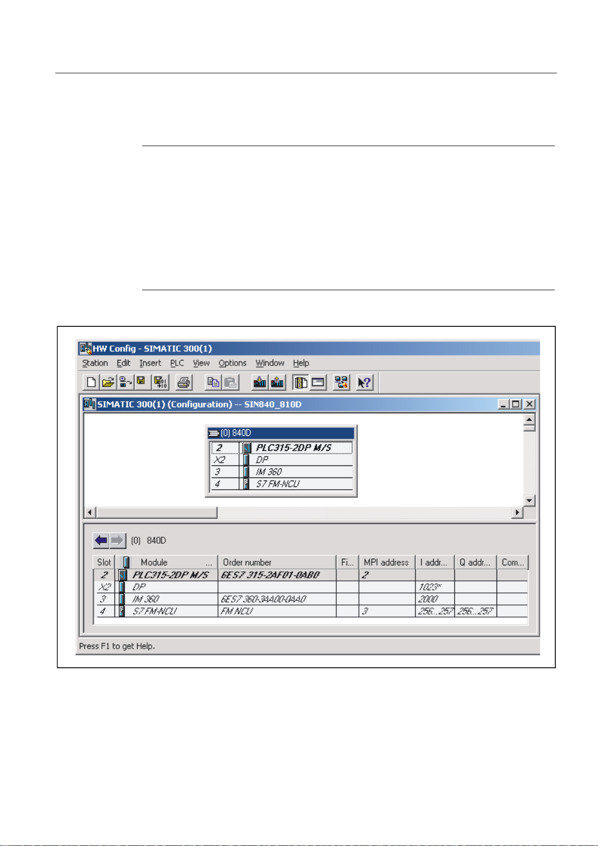
Note
On the SINUMERIK 810D or 840D, SIMATIC subrack 0 is integrated in the NC. The
following components are plugged into this subrack:
- Slot 2: The integrated PLC (PLC 314 or PLC 315-2DP)
- Slot 3: An IM 360
- Slot 4: The FM NCU.
With PLC 314, NC software version 3.5 and higher, the FM NCU must also be defined if
further MPI (C bus) devices are included in subrack 1 to subrack 3 (e.g., FM modules with C
bus connection). The properties of the FM NCU must not be changed, as process interrupts
(e.g. auxiliary functions) of the NCU may, in this case, no longer function.
Figure 2-1 Hardware configuration of row 0 on 810D, 840D
Basic logic functions: PLC Basic program powerline (P3 pl)
Function Manual, 11/2006, 6FC5397-0BP10-2BA0
21
Page 22

Detailed description
2.4 Starting up the PLC program
MCP (Machine Control Panel) and HHU (HandHeld Unit)
(only for SINUMERIK 810D to SW 3.x)
If the MCP or HHU is configured (deviation from the norm), an additional SIMATIC 300
station must be inserted into the machine project for each operator component. Any type of
CPU must be inserted in location 2 on row 0 in this station by means of the hardware
configuration (HW config.). The MPI address of the operator component must be set as the
MPI address. MPI network (1) can then be marked in the SIMATIC manager. The global data
can then be activated via the "Tools" menu item.
The rest of the procedure is described in detail in the Commissioning Manual.
2.4 Starting up the PLC program
2.4.1 Installing the basic program for 810D, 840D
Before initial startup of the NC, an NC and PLC general reset must be carried out to initialize
the relevant memory areas. To do this, set switch S3 to setting 1 and switch S4 to setting 3
and switch the control off and on again (POWER ON reset).
Installation
General
With Toolbox SW 6.1 and higher, the installation is performed by a WINDOWS-compliant
setup program for the basic program, hardware selection in STEP7 (SINUMERIK
810D/840D option package) and the NC-Var Selector. To start the installation, run
"setup.exe" in the main CD directory. You can then choose which components to install.
After the installation, you can select the basic program library directly from STEP 7
(gp8x0d61, 61 is the main basic program version).
The concrete version of the basic program can be scanned for the object properties of the
library or the program folder in the comment field.
From software version 3.7 to version 4.2, installation is carried out using INSTALL.BAT
(INSTALL1.BAT, INSTALL4.BAT).
This program installs the basic program and additional files for the relevant STEP7 version.
With automatic installation in STEP 7 V3 and higher, the TYP, GSD and meta files in the
hardware catalog are also augmented and updated.
The hardware components of the SINUMERIK system are then also available for hardware
configuration under STEP 7. This eliminates the need for unzipping, mentioned below.
The basic program is supplied in zipped format as a project for STEP 7 Version 1.x or as a
library for STEP 7 Version 2.x and subsequent versions.
The OB source programs, including standard parameterization, interface symbols and DB
templates for handheld unit and M decoding functions are enclosed in the SIMATIC project
or SIMATIC library of the basic program.
STEP 7 must be installed before the basic program.
Basic logic functions: PLC Basic program powerline (P3 pl)
22 Function Manual, 11/2006, 6FC5397-0BP10-2BA0
Page 23

Detailed description
2.4 Starting up the PLC program
STEP7 V1.x
The basic program is stored as a compressed file with the name GP840D.EXE (or
GP810D.EXE and GPFMNC.EXE) in the main directory on the diskette. The basic program
(GP840D.exe) must be copied to the main directory (root) of a drive (e.g., c:\) and then
called. The project structure required for the basic program is generated automatically. The
catalog name of the basic program is GP840Dxy.S7A. In this case, xy stands for the basic
program version.
STEP7 V2.x, 3.x
Note
When STEP 7 V1 is used, the GP840Dxy.S7A catalog must be copied to the root directory.
Any existing catalog with the same name GP840Dxy.S7A must be deleted beforehand.
The basic program is stored as a compressed file with the name "GP840D.EXE" in directory
S7V2.840 or S7V2.810 or S7V2 on the basic program diskette. The basic program
(GP840D.exe) must be copied to subcatalog "S7LIBS" of STEP7 V2 (step7_v2) or
subsequent versions thereof and then called. The library structure required for the basic
program is generated automatically. The catalog name of the basic program is GP840Dxy. In
this case, xy stands for the basic program version. The file "MET.EXE" must be copied to the
basic catalog of STEP 7 and called from there via the DOS window with "MET.EXE –O".
Note
The name GP840D specified above refers to the basic program of the SINUMERIK 840D.
The basic program is named GP810D on the SINUMERIK 810D and GPFMNC on the FMNC. With effect from SW 4.2, the basic program for 810D and 840D is combined. It is now
called GP8x0D.
Basic logic functions: PLC Basic program powerline (P3 pl)
Function Manual, 11/2006, 6FC5397-0BP10-2BA0
23
Page 24

Detailed description
2.4 Starting up the PLC program
2.4.2 Application of basic program
A new CPU program (e.g., "Turnma1") must be set up in a project by means of the STEP7
software for each installation (machine).
Comment
The catalog structures of a project and the procedure for creating projects and user
programs are described in the relevant SIMATIC documentation.
STEP7 V1
A network link to the PLC must be activated for the machine CPU program under menu
items "Edit", "Configuration". This is done in the "Services", "Parameterize" menu followed by
selection of the MPI parameters.
Default:
• "Networked"
• "MPI subnetwork number = 0"
STEP7 V2
• "CPU MPI Addr = 2"
The following must be copied into the CPU program for the machinespecific program files:
1. The basic-program blocks (FCs, FBs, DBs, OBs, SFCs, SFBs, and UDTs) ("File",
"Manage Project" menu in the Step7 program editor).
2. File GPOB840D.AWL (or GPOB810D.AWL or GPOBFMNC.AWL) and other STL (AWL)
files if appropriate must also be copied from the basic program catalog into the CPU
program. The OBs contained in this file are the basis for the user program with the
associated basic program calls. Existing user blocks must be copied as STL files to the
newly created CPU program (catalog name CPU1.S7D) and compiled.
3. We also recommend that the symbolic names are transferred with the files from the basic
program package using the symbol editor.
The basic-program blocks are copied using the SIMATIC Manager and
"File"/"Open"/"Library".
The following sections must be copied from the library:
AP off: FCs, FBs, DBs, OBs, SFC, SFB, UDT and the SDB container.
For the 810D, the SDB container includes:
• The source_files (SO):
– GPOB810D or GPOB840D
– Possibly MDECLIST, HHU_DB and others
• Symbol table (SY)
Basic logic functions: PLC Basic program powerline (P3 pl)
24 Function Manual, 11/2006, 6FC5397-0BP10-2BA0
Note
The SDB container is only included for these control variants.
Page 25

Detailed description
2.4 Starting up the PLC program
Compatibility with STEP 7
No interdependencies exist between the basic program (including older program versions)
and currently valid versions of STEP 7.
2.4.3 Version codes
Basic program
The version of the basic program is displayed on the version screen of the HMI software
along with the controller type.
User Program
The user can define his/her own version code for the PLC user program in any data block in
the form of a data string containing a maximum of 54 characters. The data can contain a text
of the user's choice. Parameter assignments for this string are made via a pointer in FB 1.
Parameterization requires symbolic definition of the data block.
References::
/FB1/ Function Manual, Basic Functions; PLC – Basic Program (P3);
Chapter: Block Description
2.4.4 Machine program
The machine manufacturer creates the machine program using the library routines supplied
with the basic program. The machine program contains the logic operations and sequences
on the machine. The interface signals to the NC are also controlled in this program. More
complex communication functions with the NC (e.g., read/write NC data, tool-management
acknowledgments, etc., are activated and executed via basic-program FCs and FBs). The
machine program can be created in different creation languages (e.g., STL, LAD, CSF, S7
HIGRAPH, S7GRAPH, SCL). The complete machine program must be generated and
compiled in the correct sequence. This means that blocks that are called by other blocks
must generally be compiled before the blocks, which call them. If blocks that are called by
other blocks are subsequently modified in the interface (VAR_INPUT, VAR_OUTPUT,
VAR_IN_OUT, VAR) as the program is developed, then the call block and all blocks
associated with it must be recompiled. This general procedure applies analogously to
instance data blocks for FBs. If this sequence of operations is not observed, timestamp
conflicts occur when the data are retranslated into STEP7. In some cases, therefore, it may
not be possible to recompile blocks, creating problems, for example, with the "Block status"
function. It is moreover advisable to generate blocks in ASCIISTL by means of the STEP7
editor when they have been created in the ladder diagram or in single statements
(incremental mode).
Basic logic functions: PLC Basic program powerline (P3 pl)
Function Manual, 11/2006, 6FC5397-0BP10-2BA0
25
Page 26

Detailed description
2.4 Starting up the PLC program
2.4.5 Data backup
The PLC-CPU does not save any symbolic names, but instead data type descriptions of the
block parameters:
• VAR_INPUT, VAR_OUTPUT, VAR_IN_OUT, VAR and
• the data types of the global data blocks.
Note
No sensible recompilation is possible without the related project for this machine. This
especially affects, for instance the function status of the block or the necessary changes
done in the PLC-CPU programs later. It is, therefore, necessary to keep a backup copy of
the STEP7 project located in the PLC CPU on the machine. This is a great help for the
service case and saves unnecessary consumption of time in restoring the original project.
If the STEP7 project exists and has been created according to the instructions given above,
then symbols can be processed in the PLCCPU on this machine. It may also be advisable to
store the machine source programs as AWL files in case they are required for any future
upgrade.
The source programs of all organization blocks and all instance data blocks should always
be available.
2.4.6 PLC series startup, PLC archives:
Generate series archive
Once the blocks have been loaded into the PLC CPU, a series archive can be generated via
the HMI operator interface for data backup on the machine. To ensure data consistency, this
backup must be created immediately after block loading when the PLC is in the Stop state. It
does not replace the SIMATIC project backup as the series archive saves binary data only,
and does not back up, e.g., symbolic information. In addition, no CPU DBs (SFC 22 DBs) or
SDBs generated in the CPU are saved.
In Toolbox 06.03.03 and STEP 7 V5.1 and higher, the PLC series archive can be generated
directly from the corresponding SIMATIC project.
To do this, select the "Options" → "Settings" menu item and the "Archive" tab in STEP 7. This
contains an entry "SINUMERIK (*.arc)", which must be selected to create a series startup
file. After selection of the archive, select the "File" → "Archive" menu item. The relevant
series archive will then be generated. If the project contains several programs, the program
path can be selected. A series archive is set up for the selected program path. All blocks
contained in the program path are incorporated into the archive, except for CPU-DBs (SFC
22 DBs).
The process of generating a series archive can be automated (comparable to the command
interface in STEP 7, V5.1 and higher). In generating this series archive, the command
interface is expanded.
Basic logic functions: PLC Basic program powerline (P3 pl)
26 Function Manual, 11/2006, 6FC5397-0BP10-2BA0
Page 27

Detailed description
2.4 Starting up the PLC program
Functions
The following functions are available for this expansion:
The functions (shown here in VB script) are not available until server instantiations and
Magic have been called:
Functions:
Const S7BlockContainer = 1138689, S7PlanContainer = 17829889
Const S7SourceContainer = 1122308
set S7 = CreateObject("Simatic.Simatic.1")
rem Instance command interface of STEP7
Set S7Ext = CreateObject("SimaticExt.S7ContainerExt")
Call S7Ext.Magic("")
Function Magic(bstrVal As String) As Long
Call gives access to certain functions. The function must be called once after server
instantiation. The value of bstrVal can be empty. This initiates a check of the correct Step7
version and path name in Autoexec. The functions are enabled with a return parameter of 0.
Return parameter (-1) = incorrect STEP 7 version
Return parameter (-2) = no entry in Autoexec.bat
Function Magic(bstrVal As String) As Long
Function MakeSeriesStartUp(FileName As String, Option As Long, Container As
S7Container) As Long
"Option" parameter:
0: Normal series startup file with general reset
Bit 0 = 1: Series startup file without general reset. When project contains SDBs, this
option is inoperative.
A general reset is then always executed.
Bit 1 = 1: Series start-up file with PLC restart
Return parameter value:
0 = OK
-1 = Function unavailable, call Magic function beforehand
-2 = File name cannot be generated
-4 = Container parameter invalid or container block empty
-5 = Internal error (memory request rejected by Windows)
-6 = Internal error (problem in STEP 7 project)
-7 = Write error when generating series startup files (e.g., diskette full)
Basic logic functions: PLC Basic program powerline (P3 pl)
Function Manual, 11/2006, 6FC5397-0BP10-2BA0
27
Page 28

Detailed description
2.4 Starting up the PLC program
Use in script
If S7Ext.Magic("") < 0 Then
Wscript.Quit(1)
End If
Set Proj1 = s7.Projects("new")
set S7Prog = Nothing
Set s7prog = Proj1.Programs.Item(1) 'if there is only one program'
For i = 1 to S7Prog.Next.Count
Next
Error = S7Ext.MakeSerienIB("f:\dh\arc.dir\PLC.arc", 0, Cont)'Error analysis now'
Set Cont = S7Prog.Next.Item(i)
Check block container
If (Cont.ConcreteType = S7BlockContainer) Then
Exit For
End if
2.4.7 Software upgrades
Software upgrade
Whenever you update the PLC or NCK software, always reset the PLC to its initial state first.
This initial clear state can be achieved by means of a general PLC reset. All existing blocks
are cleared when the PLC is reset.
It is usually necessary to include the new basic program when a new NC software version is
installed. The basic programs blocks must be loaded into the user project for this purpose.
OB 1, OB 40, OB 100, FC 12 and DB 4 should not be loaded if these blocks are already
included in the user project. These blocks may have been modified by the user. The new
basic program must be linked with the user program.
To do this, proceed as follows:
1. Generate the text or source file of all user blocks before copying the basic program.
2. Then copy the new basic program blocks to this machine project (for a description, see
Subsection "Application of basic program")
3. All user programs *.awl must then be recompiled in the correct order! (See also the
"Machine program" section.)
This newly compiled machine program must then be loaded to the PLC CPU using STEP
7.
However, it is normally sufficient to recompile the organization blocks (OB) and the instance
data blocks of the machine program. This means you only need to generate sources for the
organization blocks and the instance data blocks (before upgrading).
Basic logic functions: PLC Basic program powerline (P3 pl)
28 Function Manual, 11/2006, 6FC5397-0BP10-2BA0
Page 29

Detailed description
2.4 Starting up the PLC program
Overall reset
A description of how to perform a general PLC reset appears in the Installation and Startup
Guide. However, a general reset does not delete the contents of the diagnostic buffer nor the
node address on the MPI bus. Another possible general reset method is described below.
This method must be used when the normal general reset process does not work.
Proceed as follows:
No. Action Effect
1 Control system is switched off
2 PLC switch setting 3 (MRES) and switch control on
again or perform hardware reset.
3 Set PLC startup switch to position 2 (STOP) and
back to position 3 (MRES).
4 Set PLC startup switch to setting 2 or 0.
NC variables
The latest NC VAR selector can be used for each NC software version (even earlier
versions). The variables can also be selected from the latest list for earlier NC software
versions. The data content in DB 120 (default DB for variables) does not depend on the
software version, i.e., selected variables in an older software version must not be reselected
when the software is upgraded.
LED labeled PS flashes slowly.
The LED labeled PS starts to flash
faster.
2.4.8 I/O modules (FM, CP modules)
Special packages for STEP7 are generally required for more complex I/O modules. Some of
these special packages include support blocks (FC, FB) stored in a STEP7 library. The
blocks contain functions for operating the relevant module which are parameterized and
called by the user program. In many cases, the FC numbers of the CP and FM module
handling blocks are also included in the number range of the basic program for the 810D and
840D systems.
What action can be taken if such a conflict occurs?
The block numbers of the basic program must remain unchanged. The block numbers of
handling blocks can be assigned new, free numbers using STEP7. These new blocks (with
new FC numbers) are then called in the user program with the parameter assignments
required by the function.
Basic logic functions: PLC Basic program powerline (P3 pl)
Function Manual, 11/2006, 6FC5397-0BP10-2BA0
29
Page 30

Detailed description
2.4 Starting up the PLC program
2.4.9 Troubleshooting
This section describes problems which may occur, their causes and remedies and should be
read carefully before hardware is replaced.
Errors, cause/description and remedy
Serial
no.
error
informati
on
1 No connection
2 PLC cannot
3 All four LEDs
Errors Cause/description To correct or avoid errors
via MPI to
PLC.
be accessed
in spite of
PLC general
reset.
on the PLC
flash (DI
disaster)
The MPI cable is not plugged in
or is defective. Possibly, the
STEP 7 software is also not
correctly configured for the MPI
card.
A system data block SDB 0 has
been loaded with a modified MPI
address. This has caused an
MPI bus conflict due to dual
assignment of addresses.
A system error has occurred in
the PLC.
Measures: The diagnostic buffer
on the PLC must be read to
analyze the system error in
detail. To access the buffer, the
PLC must be stopped (e.g., set
"PLC" switch to position 2). A
hardware reset must then be
performed. The diagnostic buffer
can then be read out with
STEP7. Relay the information
from the diagnostic buffer to the
Hotline / Development Service. A
general reset must be carried out
if requested after the hardware
RESET. The diagnostic buffer
can then be read with the PLC in
the Stop state.
Test: Create a link with the
programmer in the STEP7 editor by
means of connection "Direct_PLC". A
number of node addresses must be
displayed here. If they do not appear,
the MPI cable is defective/not plugged
in.
Disconnect all MPI cables to other
components. Create the link
"Direct_PLC" with the programmer.
Correct the MPI address.
Once the PLC program has been
RESET or reloaded, the system may
return to normal operation. Even in this
case, the content of the diagnostic
buffer should be sent to the
Development Office.
Basic logic functions: PLC Basic program powerline (P3 pl)
30 Function Manual, 11/2006, 6FC5397-0BP10-2BA0
Page 31

Detailed description
2.5 Linking PLC CPUs to 810D, 840D
2.5 Linking PLC CPUs to 810D, 840D
2.5.1 General
The AS 300 family is used as the PLC for all systems. The essential difference between the
NCU variants lies in the method by which they are linked. On the 840D and 810D, the PLC
314 CPU (user memory capacity up to 128 KB) or PLC 315-2 DP (user memory capacity up
to 288 KB) is integrated as a submodule into the NC unit.
The PLC/CPU 315-2 DP also supports distributed I/Os on the PROFIBUS (L2DP). The
relevant performance data for individual PLC CPUs can be found in the above table or in
Catalog FT70.
2.5.2 Properties of PLC CPUs
SINUMERIK 810D/840D/840Di PLC CPUs are based on standard SIMATIC CPUs in the S7300 family. As a result, they generally possess the same functions. Functional deviations are
shown in the table above. Owing to differences in their memory system as compared to the
S7 CPU, certain functions are not available (e.g., blocks on memory card, project on memory
card).
Note
With the current SIMATIC CPUs, the PLC is not automatically started after voltage failure
and recovery when a PLC Stop is initiated via software operation. In this instance, the PLC
remains in the Stop state with an appropriate diagnostic entry for safety reasons. You can
start the PLC only via software operation "Execute a restart" or by setting the switch to
"Stop" and then "RUN". This behavior is also integrated in the current versions of the
SINUMERIK PLC.
Basic logic functions: PLC Basic program powerline (P3 pl)
Function Manual, 11/2006, 6FC5397-0BP10-2BA0
31
Page 32

Detailed description
2.5 Linking PLC CPUs to 810D, 840D
2.5.3 Interface on 810D and 840D with integrated PLC
Physical interfaces
As the 810D and 840D systems have an integrated PLC, signals can be exchanged between
the NCK and PLC directly via a dualport RAM.
Exchange with operator panel and MCP
Data are generally exchanged with the operator panel (OP), machine control panel (MCP)
and handheld unit (HHU) on the 840D via the operator panel interface (OPI), the COM
module being responsible for data transport.
All devices specified above can also be operated on the multipoint interface (MPI) in the
case of the 840 D. With the 810D, data communication with the operator panel (OP),
machine control panel (MCP) and handheld unit (HHU) takes place only via the MPI.
The programming device is connected directly to the PLC via the MPI (multipoint interface).
)&)%
3/&,2V
3*++8
230&3
3EXV
&%XV
03,
23,
0D
FKLQH
SURJU
'%
8VHU
LQWHU
IDFH
2SV\V
P&
P&
%DVLF
SURJU
3/&PRGXOH
&20PRGXOH
0&3
Figure 2-2 NCK/PLC connection on 810D, 840D (integrated PLC)
'35
'%
,QWHUQDO
LQWHU
IDFH
'35
1&.'3/&$6
9',
GHFRG
1&
IXQFW
([WHUQ
FRPP
Basic logic functions: PLC Basic program powerline (P3 pl)
32 Function Manual, 11/2006, 6FC5397-0BP10-2BA0
Page 33

Detailed description
2.5 Linking PLC CPUs to 810D, 840D
NCK/PLC interface
The data exchange NCK/PLC is organized on the PLC-side by the basic program.
The Status information stored by the NC in the internal Dual–Port–RAM (DPR) (such as
"Program is running") are copied by the basic program in the data blocks at the start of the
cycle (OB 1), which the user can then access (user interface). The user also enters NC
control signals (e.g. NC start) in the interface data blocks, and these are also transferred to
the NC at the start of the cycle.
Auxiliary functions transferred to the PLC dependent on the workpiece program are first
evaluated by the basic program (alarmdriven) and then transferred to the user interface at
the start of OB1. If the relevant NC block contains auxiliary functions that require the
interruption of the NC machining process (e.g. M06 for tool change), the basic program halts
the execution of the block on the NC for one PLC cycle. The user can then use the "read
disable" interface signal to halt the block execution until the tool change has been
completed. If, on the other hand, the relevant NC block does not contain auxiliary functions
requiring the interruption of the NC machining process (e.g. M08 for "Cooling on"), the
transfer of these "rapid" auxiliary functions is enabled directly in OB 40, so that block
execution is only marginally influenced by the transfer to the PLC.
The evaluation and enabling of the G functions transferred from the NCK are also alarmdriven, however they are transferred directly to the user interface. Where a G function is
evaluated at several points in the PLC program, differences in the information of the G
function within one PLC cycle may arise.
In the case of NC actions triggered and assigned with parameters by the PLC (e.g. traverse
concurrent axes), triggering and parameter assignment is performed using FCs and FBs, not
interface data blocks. The FCs and FBs belonging to the actions are supplied together with
the basic program. The FCs must be loaded by the user and called in the PLC program of
the machine manufacturer (machine program). You can find an overview of the FC, FB and
DB blocks, grouped according to their basic and extended functions, in:
References::
/FB1/Function Manual, Basic Functions; PLC Basic Program (P3);
"PLC program commissioning"
OP/PLC interface
Data are exchanged between the OP and PLC via the OP/NC serial bus, COM module and
C bus. The COM module transfers the data intact from one bus segment to another. It
merely converts the baud rate. The OP is always the active partner (client) and the PLC is
always the passive partner (server). Data transmitted or requested by the OP are read from
and written to the OP/PLC interface area by the PLC operating system (timing: cycle control
point). From the viewpoint of the PLC application, the data are identical to I/O signals.
MCP/PLC interface, HHU/PLC interface (840D only)
Data are exchanged between MCP/PLC and HHU/PLC via the serial bus MCP, HHU/NC,
COM module, and NCK. The NCK transfers the MCP/HHU signals to and fetches them from
the internal NC/NCK DPR (dual-port RAM). On the PLC side, the basic program handles
communication with the user interface. The basic program parameters define the operand
areas (e.g. I/O) and the start addresses.
Basic logic functions: PLC Basic program powerline (P3 pl)
Function Manual, 11/2006, 6FC5397-0BP10-2BA0
33
Page 34

Detailed description
2.5 Linking PLC CPUs to 810D, 840D
MCP/PLC interface, HHU/PLC interface (810D only)
Data exchange between MCP/PLC and HHU/PLC takes place via the MPI interface on the
PLC. The Communication with global data (GD)
STEP7 User's Guide). The PLC operating system handles the transfer of signals from and to
the user interface. The STEP7 Communication configuration configuring tool is used to
define both GD parameters as well as operand areas (e.g., I/O) and their initial addresses. In
SW 2.2 and higher, data exchange is possible as on the 840D.
1)
IC (GD) = Implicit Communication (Global Data)
1)
service is used for this purpose (see also
2.5.4 Diagnostic buffer on PLC
General
The diagnostic buffer on the PLC, which can be read out using STEP 7, displays diagnostic
information about the PLC operating system. Moreover, through the basic program and the
function: "Alarms / messages" are made available via the FC10 entries in the diagnostic
buffer. These alarms and messages are displayed in the diagnostic buffer as event with the
"Event-ID": <ID>" without explanatory text.
Meaning of displayed data
An example is presented below to illustrate what information is displayed for an event and
how to interpret this information.
Diagnostic buffer (extract, relevant data selected):
Event details: 1 of 10 Event ID: 16# B046
No entry in text database. Hex values are displayed.
Event ID: 16# B046
OB: 16# 01
PK: 16# 01
DatID 1/ 2: 16# 59 C9
Supplementary info1 / 2 / 3: 16# 0200 0000 0020
Outgoing event: 36:02:459 08.04.03
Type of event
The two most significant digits of Event ID 16# B046 contain the code for the event type:
A1: Alarm set
A0: Alarm cancelled
B1: Message set
B0: Message cancelled
Basic logic functions: PLC Basic program powerline (P3 pl)
34 Function Manual, 11/2006, 6FC5397-0BP10-2BA0
Page 35

Detailed description
2.5 Linking PLC CPUs to 810D, 840D
Alarm/Message Number
The two least significant digits of Event ID 16# B046 contain the code for the most significant
decimal places of the alarm or message number. The two least significant digits of
supplementary information 1 / 2 / 3 must also be taken into account when determining the
complete alarm or message number:
• Supplementary information 1 16# 0200 0000 0020
• Supplementary information 2 16# 0200 0000 0020
All values must be converted to decimal values and lined up in order of alarm or message
number:
Event ID: 46
Supplementa
ry information
1
Supplementa
ry information
2
Alarm number (BM)
1) Controlled by DB2.DBX184.0
BM = operational message
= 70
hex
00
20
= 00
hex
= 32
hex
1)
= 70 00 32
dec
dec
dec
As such, the event with the event-ID: 16# B046 and the mentioned additional information:
means "Message 700032" deleted".
Notes
• The meaning of the message number is specified by the machine manufacturer.
• Events with Event ID 16# xx28 or 16# xx29 are generated from the basic program.
• The messages stored in the diagnostic buffer can be read out via the operator interface
with the associated message texts.
Basic logic functions: PLC Basic program powerline (P3 pl)
Function Manual, 11/2006, 6FC5397-0BP10-2BA0
35
Page 36

Detailed description
2.6 Interface structure
2.6 Interface structure
2.6.1 General
Interface data blocks
The PLC user interfaces on the 840D and 810D are identical except for the data volume.
Mapping in interface data blocks is required on account of the large number of signals.
These are global data blocks from the viewpoint of the PLC program. During system startup,
the basic program creates these data blocks from current NC machine data (no. of channels,
axes, etc.). The advantage of this approach is that the minimum amount of PLC RAM
required for the current machine configuration is used.
2.6.2 PLC/NCK interface
General
Data interface
Function interface
The PLC/NCK interface comprises a data interface on one side and a function interface on
the other. The data interface contains status and control signals, auxiliary functions and G
functions, while the function interface is used to transfer jobs from the PLC to the NCK.
The data interface is subdivided into the following groups:
• NCKspecific signals
• Mode groupspecific signals
• Channelspecific signals
• Axis/spindle/drivespecific signals
The function interface is formed by FBs and FCs. The figure below illustrates the general
structure of the interface between the PLC and the NCK.
Basic logic functions: PLC Basic program powerline (P3 pl)
36 Function Manual, 11/2006, 6FC5397-0BP10-2BA0
Page 37

Detailed description
2.6 Interface structure
00&
1&
0RGH
JURXS
00&
1&FKDQQHO
'DWDLQWHUIDFH
$[LV
VSLQGOH
GULYH
'
7RRO
'%
PDQDJHPHQW
1&FKDQQHO
$[LVVSLQGOH
7RRO
PDQDJHPHQW
'ULYH
'
1&
)XQFWLRQLQWHUIDFH
'%
'%
1&
0HVVDJHV
6LJQDOVWR1&.FRPSLOHF\FOHV
6LJQDOVIURP1&.FRPSLOHF\FOHV
1&
'%
6LJQDOVWR1&
6LJQDOVIURP1&
'%
0RGHJURXS
0RGHJURXS
0RGHJURXS
'%
'%
6LJQDOVWR%$*
6LJQIURPPRGHJU
'%
00&
6LJQDOVWR00&
6LJQDOVIURP00&
'%
'%
'%
&KDQQHO
&KDQQHO
&KDQQHO
6LJQDOVWRFKDQQHO
6LJQDOVIURPFKDQQHO
$[LVVSLQGOH
'%
$[LVVSLQGOH
'%
$[LVVSLQGOH
'%
6LJQDOVWRD[LV
6LJQDOVIURPD[LV
7RROPDQDJHPHQW
-REIRUORDGLQJXQORDGLQJORFDWLRQV
-REIRUVSLQGOHDQGWXUUHW
)&
6WDUW$68%
6WDUWFRQFXUUHQWD[LVVSLQGOH
3RVLWLRQLQJD[LVLQGH[LQJD[LV
$FNQRZOHGJPHQWIRUWRROPDQDJHPHQW
'LUHFWLRQVHOHFWLRQIRUWRROPDJD]LQH
6WDUGHOWDVZLWFKRYHU
)%
5HDGZULWH1&.YDULDEOHV
3,VHUYLFHV
5HDG*8'
3/&XVHU
SURJUDP
Figure 2-3 PLC/NCK interface
Basics
Compile-cycle signals
In addition to the standard signals exchanged between the PLC and NCK, an interface data
block for compile cycles is also generated if required (DB9). The associated signals, which
are dependent on the compile cycles, are transmitted cyclically at the start of OB1.
Basic logic functions: PLC Basic program powerline (P3 pl)
Function Manual, 11/2006, 6FC5397-0BP10-2BA0
37
Page 38

Detailed description
2.6 Interface structure
Signals PLC/NC
The group of signals from the PLC to NC includes:
• Signals for modifying the highspeed digital I/O signals of the NC
• Keyswitch and emergency stop signals
Signals NC/PLC
The group of signals from the NC to PLC includes:
• Actual values of the digital and analog I/O signals of the NC
• Ready and status signals of the NC
Also output in this group are the HMI handwheel selection signals and the channel status
signals.
The signals for handwheel selection are decoded by the basic program and entered in the
machine-/axisspecific interface.
'%
&RQWURORIGLJLWDO1&.LQSXWV
2QERDUGLQSXWV
&RQWURORIGLJLWDO1&.RXWSXWV
2QERDUGRXWSXWV
5HVHUYH
.H\VZLWFK(0(5*(1&<6723
$FWXDOYDOXHVIRUGLJLWDO1&.LQSXWV
2QERDUGLQSXWV
6HWSRLQWVIRUGLJLWDO1&.RXWSXWV
2QERDUGRXWSXWV
5HVHUYH
+DQGZKHHOVHOHFWLRQ
00&VWDWXVVLJQDOV
%DVLFSURJUDPVWDWXVVLJQDOV
6WDWXVVLJQDOV
6RIWZDUHFDP
&RQWURORIGLJLWDO1&.LQSXWV
([WHUQDOLQSXWV
&RQWURORIGLJLWDO1&.RXWSXWV
([WHUQDORXWSXWV
&RQWURORIDQDORJ1&.LQSXWV
([WHUQDOLQSXWV
&RQWURORIDQDORJ1&.RXWSXWV
([WHUQDORXWSXWV
$FWXDOYDOXHVIRUGLJLWDO1&.LQSXWV
([WHUQDOLQSXWV
6HWSRLQWVIRUGLJLWDO1&.RXWSXWV
H[WHUQDORXWSXWV
$FWXDOYDOXHVIRUDQDORJ1&.LQSXWV
H[WHUQDOLQSXWV
6HWSRLQWVIRUDQDORJ1&.RXWSXWV
H[WHUQDORXWSXWV
00&
%3
1&.
'HFRGLQJKDQG
ZKHHOVHOHFWLRQ
$[LVLQWHUIDFHJHR
D[LVLQWHUIDFHLQ
FKDQQHO
%\WH
Figure 2-4 PLC/NC interface
Basic logic functions: PLC Basic program powerline (P3 pl)
38 Function Manual, 11/2006, 6FC5397-0BP10-2BA0
Page 39

Detailed description
2.6 Interface structure
Digital/analog inputs/outputs of the NCK
The following must be noted with respect to the digital and analog inputs and outputs of the
NCK:
Inputs:
• All input signals or input values of the NCK are also transferred to the PLC.
• The transfer of signals to the NC parts program can be suppressed by the PLC. Instead,
a signal or value can be specified by the PLC.
• The PLC can also transfer a signal or value to the NCK even if there is no hardware for
this channel on the NCK side.
Outputs:
• All signals or values to be output are also transferred to the PLC.
• The NCK can also transfer signals or values to the PLC even if there is no hardware for
this channel on the NCK side.
• The values transferred by the NCK can be overwritten by the PLC.
• Signals and values from the PLC can also be output directly via the NCK I/O devices.
Note
When implementing digital and analog NCK I/Os, you must observe the information in the
following references:
References:
/FB2/Function Manual, Extended Functions;
Digital and Analog NCK I/Os (A4)
Signals PLC/Mode group
The operating mode signals set by the machine control panel or the HMI software are
transferred to the operating mode group (MG) of the NCK. The mode signals are valid for all
NC channels of the mode group on the 810D and 840D. On 840D systems, several mode
groups can optionally be defined in the NCK.
The mode group reports its current status to the PLC.
%3
0RGHVHOHFWLRQ
%\WH
'%
&RQWUROVLJQDOV
0RGHVHOHFWLRQ
6HOHFWLRQVLJQDOVIURP00&
$FWLYHPRGH
00&
0RGH
*URXS
0RGHJURXS
0&3
Figure 2-5 PLC/mode group signals (e.g., mode group 1)
Basic logic functions: PLC Basic program powerline (P3 pl)
Function Manual, 11/2006, 6FC5397-0BP10-2BA0
1&.
39
Page 40

Detailed description
2.6 Interface structure
Signals PLC/NCK channels
The signal groups below must be considered on the interface:
• Control/status signals
• Auxiliary/G functions
• Tool management signals
• NCK functions
The control/status signals are transmitted cyclically at the start of OB1. The signals entered
in the channelspecific interface by the HMI software (HMI signals are entered by the PLC
operating system) are also transferred at this time if the signals have been defined on the
operator panel front, and not on the MCP.
Auxiliary functions and G functions are entered in the interface data blocks in two ways.
First, they are entered with the change signals.
• M signalsM00 - M99 * (they are transferred from the NCK with extended address 0) are
also decoded and the associated interface bits set for the duration of one cycle.
* M signals M0 - M99 are transferred from the NCK with extended address 0
• In the case of the G functions, the group is additionally decoded and the G functions
which are active in the relevant group are entered in the interface data block.
• S values are also entered together with the related M signals (M03, M04, M05) in the
spindlespecific interface. The axisspecific feedrates are also entered in the appropriate
axis-specific interface.
When the tool management function is activated in the NCK, the assignment of spindle or
revolver and the loading/unloading points are entered (DB71-73) in separate interface DBs.
The triggering and parameter assignment of NCK functions is performed by means of PLC
function calls.
The following function calls are available, for example:
• Position a linear axis or rotary axis
• Position an indexing axis
• Start a prepared asynchronous subprogram (ASUB)
• Read/write NC variables
• Update magazine assignment
Some of the above functions are described in their own function documentation.
Basic logic functions: PLC Basic program powerline (P3 pl)
40 Function Manual, 11/2006, 6FC5397-0BP10-2BA0
Page 41

Detailed description
2.6 Interface structure
'%
%\WH
%3
23VLJQDO
MXPSHULQJ
3URJUDP
FRQWURO
$FWLYDWLRQRI
SURWHFWLRQ]RQHV
7UDYHUVHVLJQDOV
*(2D[HV
3URJUDPFRQWURORI
00&
3URJUDPFKDQQHO
VWDWXV
*(2D[HVVWDWXV
$X[LOLDU\IXQFWLRQ
FKDQJHVLJQDOV
067'(+
)YDOXHV
'HFRGHG0VLJQDOV
00
$FWLYH*IXQFWLRQV
6WDWXVVLJQDOV
3URWHFWLRQ]RQHV
$[LVVSLQGOH
LQWHUIDFH
Figure 2-6 PLC/NC channel interface
&RQWURO
VLJQDOV
6WDWXVVLJQDOV
$X[LOLDU\*DFWLRQV
%3
0GHFRGHU
*JURXS
GHFRGHUV
06)
GLVWULEXWRU
0&3
00&
1&
FKDQQHO
PLC/axis, spindle, drive signals
The axis-specific and spindle-specific signals are divided into the following groups:
• Shared axis/spindle signals
• Axis signals
• Spindle signals
• Drive signals
The signals are transmitted cyclically at the start of OB1 with the following exceptions:
Exceptions include:
INC-Mode of HMI, axial F-value, M-/S-value
An axial F value is entered via the M, S, F distributor of the basic program if it is transferred
to the PLC during the NC machining process.
The M and S value are also entered via the M, S, F distributor of the basic program if an S
value requires processing together with the corresponding M value (M03, M04, M05).
.
Basic logic functions: PLC Basic program powerline (P3 pl)
Function Manual, 11/2006, 6FC5397-0BP10-2BA0
41
Page 42

Detailed description
2.6 Interface structure
'%
)HHGUDWHVSLQGOH
RYHUULGH
&RQWUROVLJQDOV
7UDYHUVHVLJQDOV
,1&PRGH
/LPLWVZLWFK
&RQWUROVLJQDOV6SLQGOHVLJQDOV
&RQWUROVLJQDOV
&RQWUROVLJQDOV
6WDWXVVLJQDOV
$FWLYH,1&PRGH
6WDWXVVLJQDOV
$[LDO)YDOXH
6HWJHDUVWDJH
6WDWXVVLJQDOV
06YDOXH
6WDWXVVLJQDOV
6WDWXVVLJQDOV
$[LV
VSLQGOH
GULYH
%3
,1&PRGH
VHOHFWLRQ
WKURXJK
B)&
B)&
0&3
%\WH
6KDUHG
D[LVVSLQGOH
VLJQDOV
$[LVVLJQDOV
'ULYHVLJQDOV
7HFKQRORJ\
*ULQGLQJ
5HVHUYH
6KDUHG
D[LVVSLQGOH
VLJQDOV
$[LVVLJQDOV
6SLQGOH
VLJQDOV
'ULYHVLJQDOV
7HFKQRORJ\
*ULQGLQJ
YDOXHVRI06DQG)GLVWULEXWRUVRIEDVLFSURJUDP
Figure 2-7 Interface between PLC and axes/spindles/drives
2.6.3 Interface PLC/HMI
General
The following groups of functions are required for the PLC/HMI interface:
• Control signals
• Machine operation
• PLC messages
• PLC status display
Control signals
Some control signals are signal inputs from the machine control panel, for example, which
have to be taken into account by the HMI software. This group of signals includes, for
example, display actual values in MCS or WCS, key disable, etc. These are exchanged via a
separate HMI interface data block (DB19).
1&.
Basic logic functions: PLC Basic program powerline (P3 pl)
42 Function Manual, 11/2006, 6FC5397-0BP10-2BA0
Page 43

Detailed description
2.6 Interface structure
Machine operation
All operator inputs, which lead to response actions on the machine, are monitored by the
PLC. Operator actions are usually performed on the machine control panel. However, it is
also possible to perform some operator actions from the operator interface (e.g. mode
selection, INC mode selection).
The PLC operating system enters the operating signals sent by the HMI directly into the
interface data blocks. In standard cases, the basic program, which decodes the operating
signals, allows the operator actions to be performed on the operator interface or on the MCP
- given that the capability for this type of operator action is available on the MCP. If required,
the user can switch off operation via HMI via an FB1 parameter "MMCToIF".
PLC messages
The signaling functions are based on the system diagnostic functions integrated in the
operating system of the AS 300. These have the following characteristics:
• The PLC operating system enters all important system states and state transitions in a
diagnostics status list. Communication events and I/O module diagnostics data (for
modules with diagnostic functions) are also entered.
• Diagnostics events, which lead to a system stop, are also entered with a time stamp in a
diagnostic buffer (circular buffer) in the chronological order of their occurrence.
• The events entered in the diagnostic buffer are automatically transmitted to
human machine interface systems via the MPI or via the OPI through the COM module,
once these have issued a ready signal (message service). Transfer to the node ready is a
function of the PLC operating system. Receipt and interpretation of the messages are
executed by the HMI software.
• An SFC (system function call) can also be used by the user program to enter messages
in the diagnostic buffer.
• The events are entered in the diagnostic buffer in coded format.
The associated message texts must be stored in the operator panel.
An FC for message acquisition (FC10) is prepared in conjunction with the basic program.
This FB records events, classifies them into signal groups and reports them to the HMI via
the diagnostic buffer.
The message acquisition structure is shown in the figure "Acquisition and signaling of PLC
events".
The features include:
• Bit fields for events related to the VDI interface are combined in a single data block (DB2)
with bit fields for user messages.
• Bit fields are evaluated at several levels by FC10.
– Evaluation 1; Acquisition of group signals
A group signal is generated for each group of signals when at least one bit signal is
set to "1". This signal is generally linked to the disable signal of the VDI interface (on
modules with diagnostic functions). The group signals are acquired completely in
cycles.
Basic logic functions: PLC Basic program powerline (P3 pl)
Function Manual, 11/2006, 6FC5397-0BP10-2BA0
43
Page 44

Detailed description
2.6 Interface structure
– Evaluation 2;Acquisition of
– Error messages
A fixed specification exists to define which signals in a group generate an error
message when they change from "0" to "1".
– Evaluation 3;Acquisition of
– Operational messages
A fixed specification exists to define which signals in a group generate an operational
message.
• The scope of the user bit fields (user area) is defined as standard as 10 areas with 8
bytes each, but can also be adjusted to suit the requirements of the machine
manufacturer via basic program parameters in FB1.
Acknowledgement concept
The following acknowledgment procedures are implemented for error and operational
messages:
Operating messages are intended for the display of normal operating states as information
for the user. Acknowledgment signals are, therefore, not required for this type of message.
An entry is made in the diagnostic buffer for incoming and outgoing messages. The HMI
software maintains an uptodate log of existing operating messages using the identifiers
"operating message arrived" and "operating message gone".
Error messages are used to display error states on the machine which generally lead to a
machine stoppage. Where several errors occur in rapid succession, it is important to be able
to distinguish their order of occurrence for troubleshooting purposes. This is indicated, on the
one hand, by the order in which they are entered in the diagnostic buffer and on the other, by
the time stamp, which is assigned to every entry.
If the cause of the error disappears, the error message is only deleted if the user has
acknowledged the message (e.g., by pressing a key on the machine control panel). In
response to this signal, the "message acquisition" FC examines which of the reported errors
have disappeared and enters these in the diagnostic buffer with the entry "error departed".
This enables the HMI software to also maintain an uptodate log of existing error messages.
The time of day indicating the time at which the error occurred is maintained for messages,
which are still pending (in contrast to a received interrogation).
Basic logic functions: PLC Basic program powerline (P3 pl)
44 Function Manual, 11/2006, 6FC5397-0BP10-2BA0
Page 45

Detailed description
2.6 Interface structure
User Program
The user PLC program merely needs to call the basic program block FC10 with appropriate
parameter settings in the cyclic program section and set or reset the bit fields in DB2. All
further necessary measures are implemented by the basic program and HMI software.
&KDQJHVLJQDOV
%LWILHOGV
&KDQQHO
&KDQQHOQ
$[LVVSLQGOH
$[LVVSLQGOHQ
*URXSVLJQDOV
GLVDEOHVLJQDOV
Figure 2-8 Acquisition and signaling of PLC events
)HHGGLVDEOH
5HDGLQGLVDEOH
1&VWDUWGLVDEOH
)HHGUDWHVSLQG
OHGLVDEOH
$FTXLVLWLRQ
*URXSVLJQDOV
IRUFKDQQHODQG
D[LV'%
0HVVDJH
DFTXLVLWLRQ
6)&:5B8606*
'LDJQRV
WLFVEXIIHU
0HVVDJHVHUYLFH
3*
2300&
3DUDPHWHUV
2.6.4 PLC/MCP/HHU interface
General
On the SINUMERIK 840D/810D, the machine control panel (MCP) is connected on the same
bus that connects the OP with the NC. The advantage of this is that only one bus cable is
required to connect the operator unit. The handheld unit (HHU) can be connected to the MPI
of the PLC or to the operator panel interface (OPI) (840D only). However, since the OP bus
on the 840D supports higher baud rates, two different types of bus topology are provided.
Basic logic functions: PLC Basic program powerline (P3 pl)
Function Manual, 11/2006, 6FC5397-0BP10-2BA0
45
Page 46

Detailed description
2.6 Interface structure
840D topology
On the 840D, the machine control panel is connected to the OPI bus segment (transmission
rate 1.5 Mbps) as an active global data node. Where the connection of further keys and
displays is required for customized operator panels, an additional keyboard (machine control
panel without operating unit) can be used. 64 pushbuttons, switches, etc. and 64 display
elements can be connected via ribbon cable.
The signals arriving from the machine control panel are copied by the COM module into the
DPR (dualport RAM) for transfer to the NC. The NC in turn transmits them to the PLC (VDI
task). The basic program of the PLC enters the incoming signals in the input image. The NCrelated signals are generally distributed by the basic program to the VDI interface. This can
be modified by the user if required.
The signals (displays) from the PLC to the MCP (displays) are transferred in the opposite
direction.
The signals of the handheld unit (HHU) are transferred either via the operator panel interface
in the same way as via the machine control panel or by means of the GD service (GD =
Global Data) of the MPI interface. The PLC operating system enters the HHU data, for
example, in the input image and transfers the display values, e.g., from the output image,
back to the HHU. The corresponding parameters are set via system data block SDB210,
which is generated with the STEP7 communication configuration tool.
8VHUNH\VGLVSOD\V
++8
3*
0&3
NEG
23
0EG
'35
):
'35
)%
3/&
0&3
VLJ
0&3
VLJ
1&&20
9',
WDVN
Figure 2-9 Connection of the machine control panel for 810D
Basic logic functions: PLC Basic program powerline (P3 pl)
46 Function Manual, 11/2006, 6FC5397-0BP10-2BA0
Page 47

Detailed description
2.6 Interface structure
810D topology
On the 810D, the machine control panel, handheld unit and OP are connected to the MPI
(multipoint Interface) of the AS 300. The transmission rate in this configuration is 187.5
Kbps. The PLC operating system copies the incoming signals straight to the user interface
(e.g., input image) at the cycle control point.
Transfer to the VDI interface is performed, as on the 840D, by the user program or by a
standard routine of the basic program.
23
8VHUNH\VGLVSOD\V
0&3
++8
NEG
3*
Figure 2-10 Connection of the machine control panel for 810D
$6
2SV\V
1&8
3EXV
&EXV
Basic logic functions: PLC Basic program powerline (P3 pl)
Function Manual, 11/2006, 6FC5397-0BP10-2BA0
47
Page 48

Detailed description
2.6 Interface structure
Bus addresses
The default bus addresses for the standard configurations are entered in the "Connecting the
MCP on the 810D" figures. In addition to the bus addresses, the implicit communication
service (global data) also requires the definition of a GD circle number.
The following should be taken into account when allocating bus addresses (node no.):
Bus addresses 840D
The two bus segments on the 840D must be examined separately:
Operator panel bus segment:
Bus station Perm. setting range Standard setting
Operator panel (OP) 1 - 31 1
Machine control
panel/keyboard interface
COM module 31 13
Programming device/PC
(e.g., for startup)
15 (setting via DIP fix)
fixed 0
PLC bus segment:
Bus station Setting range Default
setting
PLC 31 2
COM module Fixed depending on PLC
address
Programming device/PC
(e.g., for startup)
fixed 0
3
Comment
MCP interface in the PLC
The signals from the machine control panel are routed via the I/O area by default. A
distinction is made between NC and machinespecific signals. NCspecific key signals are
normally distributed by FC 19 to the various mode group, NCK, axis and spindlespecific
interfaces. The reverse applies to the status signals, which are routed to the machine control
panel interface.
Note
FC 19 must be called in the PLC user program.
Customized keys, which can be used to trigger a wide range of machine functions, must be
evaluated directly by the user program. The user program also routes the status signals to
the output area for the LEDs.
Basic logic functions: PLC Basic program powerline (P3 pl)
48 Function Manual, 11/2006, 6FC5397-0BP10-2BA0
Page 49

Detailed description
2.7 Structure and functions of the basic program
0RGHJURXSV
,1&PRGH
,%Q
4%P
$'R
$'S
'HIDXOWVHWWLQJ
'!Q P R S
'!Q P S
.H\
VLJQDOV
/LJKW
HPLWWLQJ
GLRGHV
/('V
0RQLWRULQJRIWUDQVPLW
GDWD
5HFHLYHGDWD
PRQLWRULQJ
)HHGUDWHVSLQGOHRYHUULGH
'LUHFWLRQNH\V
.H\VZLWFK
8VHUNH\V
&XUUHQWPRGH
&XUUHQW,1&PRGH
)HHGUDWHVSLQGOH1&VWDWXV
$FWLYHGLUHFWLRQNH\
6WDWXVRIFXVWRPL]HGNH\V
Figure 2-11 Interface to and from machine control panel
)&
0RGH
JURXS
1&.D[LV
VSLQGOH
LQWHUIDFH
2.7 Structure and functions of the basic program
2.7.1 General
General
The program is modular in design, i.e., it is structured according to NCK functions.
In the operating system, a distinction is made between the following levels of execution:
• Startup and synchronization (OB 100)
• Cyclic mode (OB 1)
• Process interrupt handling (OB 40)
Each section of the basic program - as illustrated in the figure below - must be called by the
user in OBs 1, 40 and 100.
Basic logic functions: PLC Basic program powerline (P3 pl)
Function Manual, 11/2006, 6FC5397-0BP10-2BA0
49
Page 50

Detailed description
2.7 Structure and functions of the basic program
2%
&ROGUHVWDUW
2%
&\FOLF
SURFHVVLQJ
2%
3URFHVVLQWHUUXSW
)%
6WDUWXS
8VHU
SURJUDP
)&
*32%
8VHU
SURJUDP
)&
*3B35$/
1&.
0RGHJURXS
&KDQQHO
$[LV
6SLQGOH
)&
0&3
++8
)&
7RROPDQDJH
PHQWQRW)01&
)&
0&3
0&3B,)0
0&3B,)7
)&
70
70B7UDQV
70B'LU
)&
6WDUGHOWD
)&
(UURUDQG
VWDWXV
PHVVDJHV
*JURXS
GLVWULEXWRU
)&
$68%
&RQ
$[HVVSLQGOHV
)%
5HDGZULWH
YDU
3,VHUYLFHV
)&
++8
'LVSOD\
FRQWURO
8VHU
SURJUDP
Figure 2-12 Structure of the PLC program
Basic logic functions: PLC Basic program powerline (P3 pl)
50 Function Manual, 11/2006, 6FC5397-0BP10-2BA0
Page 51

Detailed description
2.7 Structure and functions of the basic program
2.7.2 Startup and synchronization of NCK PLC
Loading the basic program
The basic program must be loaded with the S7 tool when the PLC is in the Stop state. This
ensures that all blocks in the basic program will be initiated correctly the next time they are
called. An undefined state may otherwise develop on the PLC (e.g., all PLC LEDs flashing).
Startup
The synchronization of NCK and PLC is performed during startup. The system and user data
blocks are checked for integrity and the most important basic program parameters are
verified for plausibility. In the event of an error, the basic program outputs an error identifier
to the diagnostic buffer and switches the PLC to STOP.
A warm restart is not provided, i.e., following system initialization, the operating system runs
organization block OB 100 and always commences cyclic execution at the start of OB 1.
Synchronization
The PLC is synchronized with the HMI and NCK during power up.
Sign of life
After a proper initial start and the first complete OB1 cycle (initial setting cycle) the PLC and
NCK continuously exchange sign of life signals. If the signoflife signal from the NCK fails to
arrive, the PLC/NCK interface is neutralized and the signal "NCK CPU ready" in DB 10 is set
to zero.
2.7.3 Cyclic operation (OB1)
General
The NCK PLC interface is processed completely in cyclic mode. From a chronological
viewpoint, the basic program runs ahead of the user program. In order to minimize the
execution time of the basic program, only the control/status signals are transmitted cyclically;
transfer of the auxiliary functions and G functions only takes place on request.
The following functions are performed in the cyclic part of the basic program:
• Transmission of the control/status signals
• Distribution of the auxiliary and G functions
• M decoding (M00 - M99),
• M, S, F distribution
• Transmission of the machine control panel signals via the NCK (on the 840D only)
• Acquisition and conditioning of the user errors and operating messages.
Basic logic functions: PLC Basic program powerline (P3 pl)
Function Manual, 11/2006, 6FC5397-0BP10-2BA0
51
Page 52

Detailed description
2.7 Structure and functions of the basic program
Control/Status signals
A shared feature of the control and status signals is that they are bit fields. The basic
program updates them at the start of OB1.
The signals can be subdivided into the following groups:
• General signals
• Mode-groupspecific signals such as operating modes
• Channelspecific signals such as program and feed modifications
Axis- and spindlespecific signals such as feed disable
Auxiliary and G functions
The auxiliary and G functions have the following characteristics:
• Transfer to the PLC is blocksynchronous (referred to a parts program block)
• Transfer is acknowledgecontrolled.
• The acknowledgment times have an immediate effect on the execution time of NC blocks
containing auxiliary functions requiring acknowledgment.
The value range is presented in the table below:
Function Structure Value range Data type
1. Value 2. Value 1. Value 2. Value 1. Value 2. Value
G function G function 2551) Byte
M word M group M word 99 99.999.999 Word DWord
S word Spindle no. S word 6 Floating
point2)
T word Magazine
no.
D word - D word 99 255 Byte Byte
H word H group H word 99 Floating
F word Axis No. F word 18 Floating
1)
relative number, transferred for each G group
2)
corresponding STEP 7 format (24-bit mantissa, 8-bit exponent)
T word 99 65535 Word Word
point
point
The M, S, T, H, D and F values sent by the NCK are output together with the accompanying
change signals to the CHANNEL DB interface via the auxiliary/G functions (see
documentation "Lists of SINUMERIK 840D, 810D"). The function value and the extended
address are transferred to the appropriate data word. The accompanying modification signal
is activated to 1 for one PLC cycle. When the modification signal is reset, the
acknowledgment is passed to the NCK. The acknowledgment of highspeed auxiliary
functions is given by the basic program immediately the basic program detects the auxiliary
function.
Word DWord
Word DWord
Word DWord
In addition to distribution of the auxiliary and G functions, selected signals are processed as
described below.
Basic logic functions: PLC Basic program powerline (P3 pl)
52 Function Manual, 11/2006, 6FC5397-0BP10-2BA0
Page 53

Detailed description
2.7 Structure and functions of the basic program
M decoder
M functions can be used to transfer both switching commands and fixed point values.
Decoded dynamic signals are output to the CHANNEL DB interface for standard M functions
(range M00 - M99); signal length = 1 cycle time.
G group decoders
In the case of G functions sent by the NCK, the related groups are decoded and the current
G number is entered in the corresponding interface byte of the CHANNEL DB, i.e., all active
G functions are entered in the channel DBs. The entered G functions are retained even after
the NC program has terminated or aborted.
Note
During system startup, all G group bytes are initialized with the value "0".
M, S, F distributor
The M, S, F, distributor is used to enter spindlespecific M words M(1...6)=[3,4,5], S words
and F words for axial feeds in the appropriate spindle and axis data blocks. The criterion for
distribution is the extended address, which is passed to the PLC for M words, S words and
axial F words.
MCP signal transmission
On the 840D, the MCP signals are transferred to the NCK via the serial bus (MPI) and from
there to the PLC. A function call from the basic program transfers the signals to the interface
of inputs and outputs specified by basic program parameters. The status signals for
controlling the LEDs on the machine control panel are passed in the opposite direction.
User messages
The acquisition and processing of the user error and operational messages is performed by
an FC in the basic program.
Basic logic functions: PLC Basic program powerline (P3 pl)
Function Manual, 11/2006, 6FC5397-0BP10-2BA0
53
Page 54

Detailed description
2.7 Structure and functions of the basic program
2.7.4 Time-alarm processing (OB 35)
General
The user must program OB 35 for time-alarm processing. The default time base setting of
OB 35 is 100 ms. Another time base can be selected using the STEP7 application "S7
Configuration". However, the OB 35 with a time base setting not less than approx. 15 ms
must not be used without additional measures, otherwise this would cause the PLC CPU to
stop. The stop is caused by reading of the system state list during power up of the HMI. This
reading process blocks priority class control for approx. 8 to 12 ms. The OB 35 with a time
base set to a rather lower value is then no longer processed correctly. If, however, small time
base settings are required for OB 35, the stop can be prevented by programming OB 80 with
at least the program command "BE".
2.7.5 Process interrupt processing (OB 40)
General
A process interrupt OB 40 (interrupt) can, for example, be triggered by appropriately
configured I/Os or by certain NC functions. Due to the different origin of the interrupt, the
PLC user program must first interpret the cause of the interrupt in OB 40. The cause of the
interrupt is contained in the local data of OB 40.
(For more information please also refer to the SIMATIC STEP7 description or the STEP7
online help).
2.7.6 Response to NC failure
General
During cyclic operation, the PLC continuously monitors NC availability by querying the signoflife character. If the NCK is no longer reacting, then the NCK PLC interface is neutralized
and IS NCK CPU ready in signals from NC group (DB 10.DBX 104.7) is reset. The signals
sent by the NCK to the PLC are also set to an initial state.
The PLC itself remains active so that it can continue to control machine functions.
Basic logic functions: PLC Basic program powerline (P3 pl)
54 Function Manual, 11/2006, 6FC5397-0BP10-2BA0
Page 55

Detailed description
2.7 Structure and functions of the basic program
Signals NCK to PLC
The signals sent by the NCK to the PLC are divided into the following groups:
• Status signals from the NCK, channels, axes and spindles
• Modification signals of the auxiliary functions
• Values of the auxiliary functions
• Values of the G functions
Status signals:
The status signals from the NCK, channels, axes, and spindles are reset.
Auxiliary-function modification signals:
Auxiliary-function modification signals are also reset.
Auxiliary-function values:
Auxiliary-function values are retained so that it is possible to trace the last functions triggered
by the NCK.
G-function values:
G-function values are reset (i.e., initialized with the value 0).
PLC → NCK signals
The signals sent by the PLC to the NCK are divided into control signals and tasks that are
transferred by FCs to the NCK.
Control signals:
The control signals from the PLC to the NCK are frozen; cyclic updating by the basic
program is suspended.
Jobs from PLC to NCK:
The FCs and FBs, which are used to pass jobs to the NCK, must no longer be processed by
the PLC user program, as this could lead to incorrect checkback signals. During runup of the
control, a job
(e.g., read NCK data) must not be activated in the user program until the NCK-CPU ready
signal is set.
Basic logic functions: PLC Basic program powerline (P3 pl)
Function Manual, 11/2006, 6FC5397-0BP10-2BA0
55
Page 56

Detailed description
2.7 Structure and functions of the basic program
2.7.7 Functions of the basic program called from the user program
General
In addition to the modules of the basic program, which are called at the start of OBs 1, 40
and 100, functions are also provided, which can be called at a suitable point in the user
program and supplied with parameters.
These functions can be used, for example, to pass the following jobs from the PLC to the
NCK:
• Traverse concurrent axes (FC 15, FC 16),
• Start asynchronous subprograms (ASUBs) (FC 9),
• Select NC programs and NC blocks (FB 4),
• Control of spindle (FC 18),
• Read/write variables (FB 2, FB 3).
Note
The following note will later help you to check and diagnose a function call (FCs, FBs of
basic program). These are FCs and FBs, which are controlled by a trigger signal (e.g., via
parameter Req, Start, etc.), and which supply an execution acknowledgment as an output
parameter (e.g., via parameter Done, NDR, Error, etc.). A variable compiled of other
signals, which produce the trigger for the function call should be set. Start conditions may
be reset only as a function of the states of parameters Done, NDR and Error.
This control mechanism may be positioned in front of or behind the function call. If the
mechanism is placed after the call, the output variables can be defined as local variables
(advantage: Reduction of global variables, flags, data variables and timerelated
advantages over data variables).
The trigger parameter must be a global variable (e.g., flag, data variable).
In OB 100, jobs still activated by the user program (Parameter Req,
Start, etc.:= TRUE) must be set to zero at the named parameters. A POWER OFF/ON
could result in a state in which jobs are still active.
Basic logic functions: PLC Basic program powerline (P3 pl)
56 Function Manual, 11/2006, 6FC5397-0BP10-2BA0
Page 57

Detailed description
2.7 Structure and functions of the basic program
Concurrent axes
The distinguishing features of concurrent axes are as follows:
• They can be traversed either from the PLC or from the NC.
• They can be started from a function call on the PLC in all operating modes.
• The start is independent of NC block boundaries.
Function calls are available for positioning (FC 15) and indexing axes (FC 16).
ASUBs
)&
6WDUW
$[LV1R
,&
,QFK
+:KHHO2Y
3RV
)5DWH
,QSXW
SDUDPHWHUV
3RV$[
,Q3RV
$FWLYH
6WDUW(UU
(UURU
2XWSXW
SDUDPHWHUV
)&
6WDUW
$[LV1R
,&
'&
3OXV
0LQXV
3RV
)5DWH
3DUW$[
,Q3RV
$FWLYH
6WDUW(UU
(UURU
Asynchronous subprograms (ASUBs) can be used to activate any selected function in the
NC. Before an asynchronous subprogram can be started from the PLC, it must be ensured
that it is available and prepared by the NC program or by FB 4 PI services (ASUB). ASUBs
can only be started in MDA or Automatic mode with running parts program.
Once prepared in this way, it can be started at any time from the PLC. The NC program
running on the channel in question is interrupted by the asynchronous subprogram. The
asynchronous subprogram is started by FC 9.
)&
$683
6WDUW
&KDQ1R
,QW1R
6WDUW(UU
5HI
Note
If an asynchronous subprogram has not been prepared by an NC program or by FB 4
(ASUB) (e.g., if no interrupt no. has been assigned), a start error is output.
Basic logic functions: PLC Basic program powerline (P3 pl)
Function Manual, 11/2006, 6FC5397-0BP10-2BA0
$FWLY
'RQH
(UURU
57
Page 58

Detailed description
2.7 Structure and functions of the basic program
Read/Write NC variables
NCK variables can be read with FB GET while values can be entered in NCK variables with
FB PUT. The NCK variables are addressed via identifiers at inputs Addr1 to Addr8. The
identifiers (symbols) point to address data, which must be stored in a global DB. To allow
generation of this DB, PC software is supplied with the basic program with which the
required variables can be selected from a table, which is also supplied. The selected
variables are first collected in a second, projectrelated list. Command Generate DB creates a
*.AWL file, which must be linked to the program file for the machine concerned and compiled
together with the machine program.
1 to 8 values can be read or written with a read or write job. If necessary, the values are
converted (e.g., NCK floating point values (64 bits) are converted to PLC format (32 bits with
24-bit mantissa and 8bit exponent) and vice versa). A loss of accuracy results from the
conversion from 64 bits to 32bit REAL. The maximum precision of 32bit REAL numbers is
approximately 10 to the power of 7.
)%
5HT
1XP9DU
$GGU
8QLW
&ROXPQ
/LQH
*(7
(UURU
1'5
6WDWH
5' 6'
)%
5HT
1XP9DU
$GGU
8QLW
&ROXPQ
/LQH
387
(UURU
'RQH
6WDWH
Basic logic functions: PLC Basic program powerline (P3 pl)
58 Function Manual, 11/2006, 6FC5397-0BP10-2BA0
Page 59

Detailed description
2.7 Structure and functions of the basic program
2.7.8 Symbolic programming of user program with interface DB
General
Note
The files NST_UDT.AWL and TM_UDT.AWL are supplied with the PLC basic program.
The compiled UDT blocks from these two files are stored in the CPU program of the basic
program.
A UDT is a data type defined by the user that can, for example, be assigned to a data block
generated in the CPU.
Symbolic names of virtually all the interface signals are defined in these UDT blocks.
The UDT numbers 2, 10, 11, 19, 21, 31, 71, 72, 73 are used.
The assignments have been made as follows:
UDT assignments
UDT
number
UDT2 DB 2 Alarms/messages
UDT10 DB10 NCK signals
UDT11 DB11 Mode group signals
UDT19 DB19 HMI signals
UDT21 DB21 to DB30 Channel signal
UDT31 DB31 to DB61 Axis/spindle signals
UDT71 DB71 Tool management: Load/unload locations
UDT72 DB72 Tool management: Change in spindle
UDT3 DB73 Tool management: Change in revolver
Assignment to interface DB Description
To symbolically program the interface signals, the interface data blocks must first be
symbolically assigned using the symbol editor.
For example, symbol "AxisX" is assigned to operand DB31 with data type UDT31 in the
symbol file.
After this input, the STEP 7 program can be programmed in symbols for this interface.
Note
Programs generated with an earlier software version that utilize the interface DBs described
above can also be converted into symbol programs. To do so, however, a fully qualified
instruction is needed for data access in the earlier program (e.g., "U DB31.DBX 60.0" - this
command is converted to "AxisX.E_SpKA" when the symbols function is activated in the
editor).
Basic logic functions: PLC Basic program powerline (P3 pl)
Function Manual, 11/2006, 6FC5397-0BP10-2BA0
59
Page 60

Detailed description
2.7 Structure and functions of the basic program
Description
Abbreviated symbolic names of the interface signals are defined in the two STL files
NST_UDT.AWL and TM_UDT.AWL.
In order to create the reference to the names of the interface signals, the name is included in
the comment after each signal.
The symbolic names, commands and absolute addresses can be viewed by means of a
STEP 7 editor command when the UDT block is opened.
Note
Unused bits and bytes are listed, for example, with the designation "f56_3".
"56": Byte address of the relevant data block
"3": Bit number in this byte
2.7.9 M decoding acc. to list
Description of functions
When the M decoding according to list function is activated via the GP parameter of
FB1 "ListMDecGrp" (number of M groups for decoding), up to 256 M functions with extended
address can be decoded by the basic program.
The assignment of the M function with extended address and the bit to be set in the signal
list is defined in the decoding list. The signals are grouped for this purpose.
The signal list contains 16 groups with 16 bits each as decoded signals.
There is only one decoding list and one signal list i.e. this is a cross-channel function.
The M functions are decoded. Once they are entered in the decoding list, then the
associated bit in the signal list is set.
When the bit is set in the signal list, the readin disable in the associated NCK channel is set
simultaneously by the basic program.
The readin disable in the channel is reset once the user has reset all the bits output by this
channel and thus acknowledged them.
The output of an M function decoded in the list as a highspeed auxiliary function does not
result in a readin disable.
The figure below shows the structure of the M decoding according to list:
Basic logic functions: PLC Basic program powerline (P3 pl)
60 Function Manual, 11/2006, 6FC5397-0BP10-2BA0
Page 61

Detailed description
2.7 Structure and functions of the basic program
&KDQQHO
1&SDUWSURJUDP
10
&KDQQHO
1&SDUWSURJUDP
10
6LJQDOVWR1&
5HDGLQ
GLVDEOH
5HDGLQ
GLVDEOH
3/&EDVLFSURJUDP
0GHFRGLQJDFF
WROLVW
3URFHVVLQJ
6WDWXVFRQWURO
VLJQDOV
ฺ
ฺ
'%
'HFRGLQJOLVW
'%
6LJQDOOLVW
'%
5HDGLQGLVDEOH
'%
5HDGLQGLVDEOH
8VHUSURJUDP
)&;
)&<
Figure 2-13 M decoding acc. to list
Activation of the function
The number of groups to be evaluated/decoded is indicated in the basic program parameter
"ListMDecGrp" when FB 1 is called in OB 100 (see also FB 1 description). M decoding is
activated if this value is between 1 and 16. Before the function is activated, the decoding list
DB75 must be transferred to the PLC followed by a restart.
Basic logic functions: PLC Basic program powerline (P3 pl)
Function Manual, 11/2006, 6FC5397-0BP10-2BA0
61
Page 62

Detailed description
2.7 Structure and functions of the basic program
Structure of decoding list
The source file for the decoding list (MDECLIST.AWL) is supplied with the basic program.
DB 75 is created when the STL source is compiled.
There must be an entry in decoding list DB 75 for every group of M functions to be decoded.
A maximum of 16 groups can be created.
16 bits are available in each group in the list of decoded signals.
The assignment between the M function with extended address and the bit to be set in the
signal list is specified via the first and last M functions in the decoding list.
The bit address is generated correspondingly from the first M function ("MFirstAdr") to the
last M function ("MLastAdr") from bit 0 up to maximum bit 15 for each group.
Each entry in the decoding lists consists of 3 parameters, each of which is assigned to a
group.
Assignment of groups
Group Extended
M address
1 MSigGrp[1].MExtAdr MSigGrp[1].MFirstAdr MSigGrp[1].MLastAdr
2 MSigGrp[2].MExtAdr MSigGrp[2].MFirstAdr MSigGrp[2].MLastAdr
... ... ... ...
16 MSigGrp[16].MExtAdr MSigGrp[16].MFirstAdr MSigGrp[16].MLastAdr
First M address in group Last M address in group
Signal list
Type and value range for signals
Signal Type Value range Remark
MExtAdr Int 0 ... 99 Extended M address
MFirstAdr DInt 0 to 99.999.999 First M address in group
MLastAdr Dint 0 to 99.999.999 Last M address in group
Data block DB 76 is set up when the function is activated.
A bit is set in the appropriate group in DB 76 for an M signal decoded in the list.
At the same time, a readin disable is set in the channel in which the M function has been
output.
Basic logic functions: PLC Basic program powerline (P3 pl)
62 Function Manual, 11/2006, 6FC5397-0BP10-2BA0
Page 63

Detailed description
2.7 Structure and functions of the basic program
Example
Three groups of M commands are to be decoded in the following example:
• · M2 = 1 to M2 = 5
• · M3 = 12 to M3 = 23
• · M40 = 55
Structure of the decoding list in DB 75:
Example parameters
Group Decoding list (DB 75) Signal list
Extended
M address
1 2 1 5 DBX0.0 to DBX0.4
2 3 12 23 DBX2.0 to DBX3.3
3 40 55 55 DBX4.0
First
M address
in group
Last
M address
in group
DB 76
DATA_BLOCK DB 75
TITLE =
VERSION : 0.0
STRUCT
END_STRUCT;
BEGIN
MSigGrp[1].MExtAdr := 2;
MSigGrp[1].MFirstAdr
:=
MSigGrp[1].MLastAdr
:=
MSigGrp[2].MExtAdr := 3;
MSigGrp[2].MFirstAdr
:=
MSigGrp[2].MLastAdr
:=
MSigGrp[3].MExtAdr := 40;
MSigGrp[3].MFirstAdr
:=
MSigGrp[3].MLastAdr
:=
END_DATA_BLOCK
MSigGrp : ARRAY [1 .. 16 ] OF STRUCT
MExtAdr : INT ;
MFirstAdr : DINT;
MLastAdr : DINT;
END_STRUCT;
L#1;
L#5;
L#12;
L#23;
L#55;
L#55;
Basic logic functions: PLC Basic program powerline (P3 pl)
Function Manual, 11/2006, 6FC5397-0BP10-2BA0
63
Page 64

Detailed description
2.7 Structure and functions of the basic program
Structure of FB 1 in the OB100
(enter the number of M groups to be decoded in order to activate the function):
Call FB 1, DB 7(
...
ListMDecGrp := 3,// M decoding of three groups
....
);
The appending of the entry in OB 100 and transfer of DB 75 (decoding list) to the AG must
be followed by a restart. During the restart, the basic program sets up DB76 (signal list).
If the NC program is started at this point and the expanded M function (e.g., M3=17) is
processed by the NCK, this M function will be decoded and bit 2.5 set in DB 76 (see
decoding list DB 75). At the same time, the basic program sets the read-in disable and the
processing of the NC program is halted (in the corresponding NC-channel DB the entry
"expanded address M function" and "M function no." is made).
The readin disable in the channel is reset once the user has reset and, therefore,
acknowledged, all the bits output by this channel in the signal list (DB 76).
Basic logic functions: PLC Basic program powerline (P3 pl)
64 Function Manual, 11/2006, 6FC5397-0BP10-2BA0
Page 65

Detailed description
2.7 Structure and functions of the basic program
2.7.10 PLC machine data
General
The user has the option of storing PLCspecific machine data in the NCK. The user can then
process these machine data after the power-up of the PLC (OB 100). This enables, for
example, user options, machine expansion levels, machine configurations, etc., to be
implemented.
The interface for reading these data lies in the DB 20. However, DB20 is set up by the basic
program during powerup only when user machine data are used i.e. sum of GP parameters
"UDInt", "UDHex" and "UDReal" is greater than zero.
The size of the individual areas and thus also the total length of DB20
is set by PLC machine data:
MD14504 MAXNUM_USER_DATA_INT
MD14506 MAXNUM_USER_DATA_HEX
MD14508 MAXNUM_USER_DATA_FLOAT
is set and specified to the user in the GP parameters:
"UDInt", "UDHex" and "UDReal"
.
The data is stored in the DB 20 by the BP in the sequence:
Integer-MD, Hexa-Fields-MD, Real-MD.
The integer and real values are stored in DB 20 in S7 format.
Hexadecimal data are stored in DB20 in the order in which they are input (use as bit fields).
'%
8VHUPDFKLQH
GDWDW\SH,17
8VHUPDFKLQH
GDWDW\SH%<7(
8VHUPDFKLQH
GDWDW\SH5($/
Figure 2-14 DB 20
1RRI8',QW
1RRI8'+H[
1RRI8'5HDO
Basic logic functions: PLC Basic program powerline (P3 pl)
Function Manual, 11/2006, 6FC5397-0BP10-2BA0
65
Page 66

Detailed description
2.7 Structure and functions of the basic program
Example
Note
If the number of PLC machine data used is increased later, then DB20 must be deleted
beforehand. To prevent such extensions in use having any effect on the existing user
program, the data in DB20 should be accessed in symbolic form wherever possible, e.g., by
means of a structure definition in the UDT.
Interrupts
400120 Delete DB 20 in PLC and restart
Explanation DB length is not the same as the required DB length
Response Interrupt display and PLC Stop
To correct or
avoid errors
Continuation After cold restart
Delete DB 20 followed by RESET
The project in the example requires 4 integer values, 2 hexadecimal fields with bit
information and 1 real value.
Machine data:
MD14510 USER_DATA_INT[0] 123
MD14510 USER_DATA_INT[1] 456
MD14510 USER_DATA_INT[2] 789
MD14510 USER_DATA_INT[3] 1011
...
MD14512 USER_DATA_HEX[0] 12
MD14512 USER_DATA_HEX[1] AC
...
MD14514 USER_DATA_FLOAT[0] 123.456
GP Parameter (OB 100):
CALL FB 1, DB 7 (
MCPNum := 1,
MCP1In := P#E0.0,
MCP1Out := P#A0.0,
MCP1StatSend := P#A8.0,
MCP1StatRec := P#A12.0,
MCP1BusAdr := 6,
MCP1Timeout := S5T#700MS,
MCP1Cycl := S5T#200MS,
NCCyclTimeout := S5T#200MS,
Basic logic functions: PLC Basic program powerline (P3 pl)
66 Function Manual, 11/2006, 6FC5397-0BP10-2BA0
Page 67

Detailed description
2.7 Structure and functions of the basic program
NCRunupTimeout
:=
S5T#50S;
BP parameters (to scan runtime):
l gp_par.UDInt; //=4,
l gp_par.UDHex; //=2,
l gp_par.UDReal; //=1 )
During PLC power-up, DB20 was generated with a length of 28 bytes:
DB 20
address data
0.0 123
2.0 456
4.0 789
6.0 1011
8.0 b#16#12
9.0 b#16#AC
10.0 1.234560e+02
The structure of the machine data used is specified in a UDT:
TYPE UDT 20
STRUCT
UDInt : ARRAY [0 .. 3 ] OF INT ;
UDHex0 : ARRAY [0 .. 15 ] OF BOOL ;
UDReal : ARRAY [0 .. 0 ] OF REAL
;
END_STRUCT;
//Description as field, for
// later expansions
END_TYPE
Note
ARRAY OF BOOL are always sent to even-numbered addresses. For this reason, an array
range of 0 to 15 must generally be selected in the UDT definition or all Boolean variables
specified individually.
Although only a REAL value is used initially in the example, a field (with one element) has
been created for the variable. This ensures that extensions can be made easily in the future
without the symbolic address being modified.
Basic logic functions: PLC Basic program powerline (P3 pl)
Function Manual, 11/2006, 6FC5397-0BP10-2BA0
67
Page 68

Detailed description
2.7 Structure and functions of the basic program
Symbolic accesses
An entry is made in the symbol table to allow data access in symbolic form:
Symbol Operand Data type
UData DB 20 UDT 20
Access operations in user program (list includes only symbolic read access):
...
L "UData".UDInt[0];
L "UData".UDInt[1];
L "UData".UDInt[2];
L "UData".UDInt[3];
U "UData".UDHex0[0];
U "UData".UDHex0[1];
U "UData".UDHex0[2];
U "UData".UDHex0[3];
U "UData".UDHex0[4];
U "UData".UDHex0[5];
U "UData".UDHex0[6];
U "UData".UDHex0[7];
... ...
U "UData".UDHex0[15];
L "UData".UDReal[0];
...
Basic logic functions: PLC Basic program powerline (P3 pl)
68 Function Manual, 11/2006, 6FC5397-0BP10-2BA0
Page 69

Detailed description
2.7 Structure and functions of the basic program
2.7.11 Configuration of machine control panel, handheld unit
General
The communications system integrated in the NC permits a maximum of 2 machine control
panels and one handheld unit to exchange data with the 810D and the 840D. An SDB210 is
not required to transfer the signals of these components. The information given below is
based on the assumption that no SDB210 has been installed for the components concerned.
Parameterization of components is always performed by means of a call of basic program
block FB1 in OB100. FB1 stores its parameters in the associated instance data block (DB7,
symbolic "gp_par"). Separate parameter sets are provided for each machine control panel
and the handheld unit. The input/output addresses of the user must be defined in these
parameter sets. These input and output addresses are also used in FC19, FC24, FC25,
FC26 and FC13. Addresses for status information, MPI or OPI (a GD parameter set must be
set for the handheld unit rather than an MPI address) must also be defined. The default time
settings for timeout and cyclic forced retriggering do not have to be changed.
Activation
Each component is activated either via the number of machine control panels (parameter
MCPNum) or, in the case of the handheld unit, parameter BHG := 2 (BHG := 1 corresponds
to a link via the MPI interface in conjunction with an SDB210). Whether a component is to be
linked to the OPI or the MPI is determined by parameters MCPMPI and BHGMPI.
Handheld unit
Control signals
The handheld unit addresses the MPI or OPI by means of a GD parameter set. These
parameter values must be assigned according to the handheld unit settings. However, the
parameter names on the handheld unit are the reverse of the parameter names in the basic
program. All Send type parameters on the handheld unit must be defined as Rec type (and
Rec in Send type) in the basic program.
Parameters MCP1Stop, MCP2Stop and BHGStop can be used to stop communication with
individual components (parameter setting = 1). This stop or activation of communication can
be applied in the current cycle. However, the change in value must be implemented through
the symbolic notation of the parameters and not by means of another FB 1 call.
Example of stopping transfer from the first machine control panel:
SET;
S
gp_par.MCP1Stop;
Setting parameters MCP1Stop, MCP2Stop, BHGStop also results in a suppression of alarms
40260 to 40262.
Basic logic functions: PLC Basic program powerline (P3 pl)
Function Manual, 11/2006, 6FC5397-0BP10-2BA0
69
Page 70

Detailed description
2.7 Structure and functions of the basic program
MPI switchover, OPI address
An existing connection with an MCP (Machine Control Panel) or HHU (HandHeld Unit) can
be aborted. Another MCP or HHU component already connected to the bus (with another
MPI or OPI address) can then be activated. Proceed as follows to switch addresses:
1. Stop communication with component to be decoupled via parameter MCP1Stop or
MCP2Stop or BHGStop = 1.
2. After checkback in DB10 byte 104 (relevant bits 0, 1, 2 set to 0). Change in the bus
address or GD parameter set of this unit to that of the new component.
3. In this PLC cycle, communication with the new component can now be activated again by
means of parameter MCP1Stop or MCP2Stop or BHGStop = 0.
4. Communication with the new component is taking place when the checkback in DB10
byte 104 (relevant bits 0, 1, 2 is set to 1).
As described in Section Control signals, all parameters must be programmed according to
data type.
Switching off flashing MCP:
With MCP firmware V5.01.02 and higher, flashing can be suppressed in offline mode. No
communication takes place in offline mode (e.g., if the MCP connection fails). Via the status
bits 24 or 25 in the MCP1StatSend, MCP2StatSend a value can be specified in the output
data when the communication is active.
The acknowledgement that the value as been imported, is returned in the same bits in the
MCP1StatRec, MCP2StatRec. Following a successful checkback signal, the status bits in
send status must be reset.
Example about realization is present on the toolbox.
Temperature monitoring of the MCP:
With MCP firmware V5.01.02 and higher, an increased temperature is signaled back via bit
28 = 1 in MCP1StatRec, MCP2StatRec.
Basic logic functions: PLC Basic program powerline (P3 pl)
70 Function Manual, 11/2006, 6FC5397-0BP10-2BA0
Page 71

Detailed description
2.7 Structure and functions of the basic program
Configuring
Essentially, there are two communication mechanisms for transferring data between the
MCP/HHU and PLC. These mechanisms are determined by the connection of the MCP and
HHU. With the first mechanism, data are transported via the COM module (840D/810D). The
parameter setting is thereby done completely via the MSTT/BHG parameter in the FB1.
In the second case, data are transferred via the PLC operating system (FM-NC) by means of
the evaluation of SDB210 (global data) or via the Profibus configuration. The mechanism is
parameterized via STEP7 -> Global Data or in HW Config. To allow the basic program to
access these data and implement MCP/HHU failure monitoring, the addresses set via
SDB210 (global data) must be declared in the FB1 parameters in the basic program.
An overview of the various interfacing options as a function of the NC type used is given
below. In each case, the parameter set of FB1 and the valid status information relevant for
the respective data transmission method are specified.
If an error is detected due to a timeout monitor, a corresponding entry is made in the
diagnostic buffer of the PLC CPU (errors 400260 to 400262). In this case, the input signals
from the MCP or from the handheld unit (MCP1In/MCP2In or BHGIn) are initialized with 0. If
it is possible to resynchronize the PLC and MCP/HHU, communication is resumed
automatically and the error message reset by the BP.
840D: OPI/MPI connection
Communication starts from the PLC BP via the NCK and COM mode, i.e., even a link via the
MPI does not require an SDB210. Parameter settings are made via the relevant parameters
in FB1.
23,
&200
PRGXOH
LQW
3/&
'
1&.
3
5
'
3
5
03,
0&3
0&3
++8
Figure 2-15 840D: OPI/MPI connection
Relevant parameters (FB1)
MCP HHU
MCPNum=1 or 2 (number of MCPs) BHG=2
(transfer via COM module)
MCP1In MCP2In BHGIn
MCP1Out MCP2Out BHGOut
MCP1StatSend MCP2StatSend BHGStatSend
MCP1StatRec MCP2StatRec BHGStatRec
MCP1BusAdr MCP2BusAdr BHGInLen
MCP1Timeout MCP2Timeout BHGOutLen
MCP1Cycl MCP2Cycl BHGTimeout
MCPMPI = FALSE (OPI), TRUE (MPI) BHGCycl
Basic logic functions: PLC Basic program powerline (P3 pl)
Function Manual, 11/2006, 6FC5397-0BP10-2BA0
71
Page 72

Detailed description
2.7 Structure and functions of the basic program
Relevant parameters (FB1)
MCP HHU
MCP1Stop MCP2Stop BHGRecGDNo
MCPBusType=0 BHGRecGBZNo
BHGRecObjNo
BHGSendGDNo
BHGSendGBZNo
BHGSendObjNo
BHGMPI = FALSE (OPI), TRUE
(MPI)
BHGStop
Status information
Available in Bit No. Description
MCP1StatSend
MCP2StatSend
BHGStatSend
MCP1StatSend
MCP2StatSend
BHGStatSend
MCP1StatRec
MCP2StatRec
BHGStatRec
4 Syntax error in GD package:
Error in parameter set (FB1)
27 Transmitter:
Time-out
10 Receiver:
Time-out
An error entry is also made in the PLC diagnostic buffer for timeouts (bits 10 and 27),
resulting in the following error messages on the operator interface:
• 400260: MCP 1 failure
• 400261: MCP 2 failure
• 400262: HHU failure
An MSTT or BHG failure is detected immediately after a cold restart even if no data have yet
been exchanged between the MSTT/BHG and PLC.
The monitoring function is activated, as soon as all the components report "Ready" after the
power-up.
840D: MPI connection for HHU (not for new development)
Communications for HHU by PLC operating system and parameterization via SDB210.
Communication for the MCP is controlled from the PLC BP via the NCK and COM module as
described above.
Basic logic functions: PLC Basic program powerline (P3 pl)
72 Function Manual, 11/2006, 6FC5397-0BP10-2BA0
Page 73

Detailed description
2.7 Structure and functions of the basic program
23,
'
&200
PRGXOH
LQW3/&
6'%
IRU++8
Figure 2-16 840D: MPI connection for HHU
1&.
3
5
'
3
5
03,
0&3
0&3
++8
Relevant parameters (FB1):
Communication between the PLC and HHU is implemented through configuring and
subsequent loading of SDB210 (Global Data). To allow the basic program to access the
HHU data and implement HHU failure monitoring, the addresses set via global data must be
declared in FB1 parameters.
Relevant parameters (FB1)
MCP HHU
(parameterization via SDB210)
Parameter settings are made via the
relevant parameters in FB1.
BHGIn (as parameterized in SDB210)
BHGOut (as parameterized in SDB210)
BHGStatRec (as parameterized in SDB210)
BHGTimeout (as parameterized in SDB210)
BHG = 1 (transfer via SDB210)
Status information (MCP1 and MCP2 see table Status information)
Available in Bit No. Description
BHGStatRec 10 Receiver: Time-out
An error entry is also made in the PLC diagnostic buffer for timeouts,
resulting in error message 400262 on the operator interface: HHU failure
An HHU failure is only recognized if data exchange has taken place previously with the HHU.
The first exchange of data with the HHU activates the monitoring function.
MPI connection
Communication starts from the PLC BP via the NCK and COM mode, i.e., even a link via the
MPI does not require an SDB210. Parameter settings are made via the relevant parameters
in FB1.
Basic logic functions: PLC Basic program powerline (P3 pl)
Function Manual, 11/2006, 6FC5397-0BP10-2BA0
73
Page 74

Detailed description
2.7 Structure and functions of the basic program
3/&&38
1&.
0&3
03,
0&3
++8
Figure 2-17 MPI connection
Relevant parameters (FB1)
MCP HHU
MCPNum=1 or 2 (number of MCPs) BHG=2
(transfer via COM module)
MCP1In MCP2In BHGIn
MCP1Out MCP2Out BHGOut
MCP1StatSend MCP2StatSend BHGStatSend
MCP1StatRec MCP2StatRec BHGStatRec
MCP1BusAdr MCP2BusAdr BHGInLen
MCP1Timeout MCP2Timeout BHGOutLen
MCP1Cycl MCP2Cycl BHGTimeout
MCPMPI = TRUE (MPI) BHGCycl
MCP1Stop MCP2Stop BHGRecGDNo
MCPBustype=0 BHGRecGBZNo
BHGRecObjNo
BHGSendGDNo
BHGSendGBZNo
BHGSendObjNo
BHGMPI = TRUE (MPI)
BHGStop
Basic logic functions: PLC Basic program powerline (P3 pl)
74 Function Manual, 11/2006, 6FC5397-0BP10-2BA0
Page 75

Detailed description
2.7 Structure and functions of the basic program
Status information
Available in Bit No. Description
MCP1StatSendMCP2Stat
Send
BHGStatSend
MCP1StatSendMCP2Stat
SendB
HGStatSend
MCP1StatRec
MCP2StatRec
BHGStatRec
4 Syntax error in GD package:
Error in parameter set (FB1)
27 Transmitter:
Time-out
10 Receiver:
Time-out
An error entry is also made in the PLC diagnostic buffer for timeouts (bits 10 and 27),
resulting in the following error messages on the operator interface:
• 400260: MCP 1 failure
Or
• 400261: MCP 2 failure
• 400262: HHU failure
An MSTT or BHG failure is detected immediately after a cold restart even if no data have yet
been exchanged between the MSTT/BHG and PLC.
The monitoring function is activated, as soon as all the components report "Ready" after the
power-up.
MPI connection and 810D (SW 4 and lower)
Communications for MCP and HHU by PLC operating system and parameterization via
SDB210.
3/&&38
6'%
IRU0&3
DQG++8
Figure 2-18 MPI connection and 810D
1&.
03,
0&3
0&3
++8
Basic logic functions: PLC Basic program powerline (P3 pl)
Function Manual, 11/2006, 6FC5397-0BP10-2BA0
75
Page 76

Detailed description
2.7 Structure and functions of the basic program
Relevant parameters (FB1):
Communication between the PLC and HHU is implemented through configuring and
subsequent loading of SDB210 (Global Data). To allow the basic program to access the
HHU data and implement HHU failure monitoring, the addresses set via global data must be
declared in FB1 parameters.
Relevant parameters (FB1) (all entries as parameterized in SDB210 global data)
MCP HHU
MCPNum=1 or 2 (number of MCPs) BHG=1 (MPI)
MCP1In MCP2In BHGIn
MCP1Out MCP2Out BHGOut
MCP1StatRec MCP2StatRec BHGStatRec
MCP1Timeout MCP2Timeout BHGTimeout
Status information
Available in Bit No. Description
MCP1StatRec
MCP2StatRec
BHGStatRec
10 Receiver: Time-out
An error entry is also made in the PLC diagnostic buffer for timeouts,
resulting in the following error messages on the operator interface:
• 400260: MCP 1 failure
• 400261: MCP 2 failure
• 400262: HHU failure
An MCP/HHU failure is only detected following a cold restart if the unit has already been
involved in data exchange. The first exchange of data with the MCP/HHU activates the
monitoring function.
840D: PROFIBUS connection
With an MCP PROFIBUS connection, these components must be considered in the STEP 7
hardware configuration. The addresses must be stored in the input and output log range.
These start addresses must also be stored in the pointer parameters of the FB1. The FB1
parameters listed below are used for further parameterization. There is no PROFIBUS
variant of the HHU. For this reason, an OPI connection is shown for the HHU in this diagram.
PROFIBUS slave address can be stored in MCP1BusAdr and MCPBusAdr.
Basic logic functions: PLC Basic program powerline (P3 pl)
76 Function Manual, 11/2006, 6FC5397-0BP10-2BA0
Page 77

Detailed description
2.7 Structure and functions of the basic program
23,
'
3
5
1&
03,'3
'3
0&3
0&3
++8
&2
LQW
352),
%86IRU
0&
Relevant parameters (FB1)
MCP HHU
MCPNum = 1 or 2 (number of MCPs) HHU = 2 (via COM module)
MCP1In MCP2In BHGIn
MCP1Out MCP2Out BHGOut
MCP1StatSend (n.r.) MCP2StatSend (n.r.) BHGStatSend
MCP1StatRec (n.r.) MCP2StatRec (n.r.) BHGStatRec
MCP1BusAdr MCP2BusAdr BHGInLen
MCP1Timeout (n.r.) MCP2Timeout (n.r.) BHGOutLen
MCP1Cycl (n.r.) MCP2Cycl (n.r.) BHGTimeout
MCPMPI = FALSE BHGCycl
MCP1Stop (n.r.) MCP2Stop (n.r.) BHGRecGDNo
MCPBusType = 3 BHGRecGBZNo
BHGRecObjNo
BHGSendGDNo
BHGSendGBZNo
BHGSendObjNo
BHGMPI = FALSE
BHGStop
MCP failure switches the PLC to the STOP state. If this is undesirable, OB 82, OB 86 can be
used to avoid a stop. Furthermore, the MCP (as Profibus slave) can also be
activated/deactivated via the SFC12.
Alarm messages are not generated by the basic program in case of a failure.
M to N is not possible with the MCP version.
Basic logic functions: PLC Basic program powerline (P3 pl)
Function Manual, 11/2006, 6FC5397-0BP10-2BA0
77
Page 78

Detailed description
2.8 SPL for Safety Integrated
2.8 SPL for Safety Integrated
See:
References:
/FBSI/Description of Functions, Safety Integrated
2.9 Assignment overview
2.9.1 Assignment: NC/PLC interface
The assignment of the NC/PLC interface is comprehensively described in:
References:
/LIS/ Lists
2.9.2 Assignment: FB/FC
FB number FC number Meaning
1 Basic program
2 - 29 Reserved for Siemens
1 Reserved for Siemens
2 - 29 Reserved for Siemens
30 - 35 See below: ShopMill, ManualTurn
30 – 127 (siehe
30 – 127 (see
Note)
Note
The actual upper limit of the block number (FB/FC) depends on the active PLC CPU which is
located in the selected NCU. See section "Key PLC CPU data for 810D, 840D". For FC and
FB assignment, see section "Memory requirements of basic PLC program for 810D, 840D".
1)
Note)
User area
User area
Basic logic functions: PLC Basic program powerline (P3 pl)
78 Function Manual, 11/2006, 6FC5397-0BP10-2BA0
Page 79

Detailed description
2.9 Assignment overview
ManualTurn
ManualTurn uses FC 30 to 35 and DB 81 to 89.
ManualTurn is an operating system for conventional, cyclecontrolled turning machines. The
above FCs and DBs can be used provided that the machine to be configured is not a turning
machine with a maximum of two axes and one spindle. If your machine is of this type and if
you might require conventional operating methods in addition to CNC functions, then you
should not use the FCs and DBs above.
ShopMill
ShopMill uses FC30 to 35 and DB 81 to 89.
ShopMill is an operating system for 2 1/2D milling machines in the workshop environment.
The above FCs and DBs can be used provided that the machine to be configured is not a
milling machine for 2 1/2D machining operations. However, if you intend to use your machine
for applications of this type, then the FCs and DBs should not be used.
2.9.3 Assignment: DB
Note
Only as many data blocks as are required according to the NC machine data configuration
are set up.
Overview of data blocks
DB no. Designation Name Packa
ge
1 Reserved for Siemens BP
4 PLC-MELD PLC messages BP
8 Reserved for Siemens
9 NC-COMPILE Interface for NC compile cycles BP
10 NC INTERFACE Central NC interface BP
11 Mode group 1 Interface mode group BP
12 Computer link and transport system interface
14 Reserved for Siemens
15 Basic program
16 PI Service definition
17 Version ID
18 Reserved for basic program
19 HMI interface
20 PLC machine data
Basic logic functions: PLC Basic program powerline (P3 pl)
Function Manual, 11/2006, 6FC5397-0BP10-2BA0
79
Page 80

Detailed description
2.9 Assignment overview
Overview of data blocks
DB no. Designation Name Packa
ge
21 - 30 CHANNEL 1 ... n Interface NC channels BP
BP 31 - 61 AXIS 1 ... m Interfaces for axes/spindles
or free for user assignment
62 - 70 Free for user assignment
71 - 74 Tool management BP
75 - 76 M group decoding
77 - 80 Reserved for Siemens
81 - 89 See below: ShopMill, ManualTurn
81 –127
(see Note)
User area
ManualTurn
ShopMill
Note
The actual upper limit of the block number (DB) depends on the active PLC CPU which is
located in the selected NCU. See section "Key PLC CPU data for 810D, 840D".
ManualTurn uses FC30 to 35 and DB81 to 89.
ManualTurn is an operating system for conventional, cyclecontrolled turning machines. The
above FCs and DBs can be used provided that the machine to be configured is not a turning
machine with a maximum of two axes and one spindle. If your machine is of this type and if
you might require conventional operating methods in addition to CNC functions, then you
should not use the FCs and DBs above.
ShopMill uses FC30 to 35 and DB81 to 89.
ShopMill is an operating system for 2 1/2D milling machines in the workshop environment.
The above FCs and DBs can be used provided that the machine to be configured is not a
milling machine for 2 1/2D machining operations. However, if you intend to use your machine
for applications of this type, then the FCs and DBs should not be used.
Basic logic functions: PLC Basic program powerline (P3 pl)
80 Function Manual, 11/2006, 6FC5397-0BP10-2BA0
Page 81

Detailed description
2.10 Memory requirements of basic PLC program for 840D
2.9.4 Assignment: Timers
Timer No. Meaning
0 - 9 Reserved for Siemens
10 – 127 User area
Note
The actual upper limit of the block number (timer) depends on the active PLC CPU which is
located in the selected NCU. See section "Key data of PLC CPUs for 810D, 840D".
2.10 Memory requirements of basic PLC program for 840D
General
The basic program consists of basic and optional functions. The basic functions include
cyclic signal exchange between the NC and PLC.
The options include, for example, the FCs, which can be used if required.
The table below lists the memory requirements for the basic functions and the options. The
data quoted represent guide values, the actual values depend on the current software
version.
Memory requirements of blocks with SINUMERIK 840D
Block
type no.
Basic functions in basic program
FB 1, 15, 16, 17,
18
FC 1, 2, 3, 4, 11,
20
DB 4, 5, 7, 8, 17,
19
DB 2, 3, 6 Are generated by the BP 992 812
OB 1, 40, 100 Must be loaded 490 282
Total 14796 11720
Function
Must be loaded 3616 3052
Must be loaded 7208 6608
Must be loaded 2490 966
Remark
Block size (bytes)
Load
memory
Working
memory
Basic logic functions: PLC Basic program powerline (P3 pl)
Function Manual, 11/2006, 6FC5397-0BP10-2BA0
81
Page 82

Detailed description
2.10 Memory requirements of basic PLC program for 840D
PLC/NCK, PLC/HMI interface
DB 10 PLC/NCK signals Must be loaded 318 262
DB 11 Signals PLC/Mode group Is generated by BP 80 44
DB 21, 30 PLC/channel signals Are generated by BP as a function of NCMD 352 each 316 each
DB 31, ...61 PLC/axis or spindle
signals
Are generated by BP as a function of NCMD 180 each 144 each
Basic program options
Machine control panel
FC 19 Transfer of MCP signals,
M variant
FC 25 Transfer of MCP signals,
T variant
FC 24 Transfer of MCP signals,
slim variant
FC 26 Transfer of MCP signals,
HPU variant
FC 14 MPI/OPI transfer Must be loaded if MCPNum > 0 942 802
Handheld unit
FC 13 Display control HHU Can be loaded for handheld units 1264 1044
Error/operating messages
FC 10 Acquisition FM/BM Load when FM/BM is used 1572 1350
ASUB
FC 9 ASUB start Load when PLC ASUBs are used 656 538
Must be loaded when M variant of MCP is
installed
Must be loaded when T variant of MCP is
installed
Must be loaded when slim variant of MCP is
installed
Must be loaded for HPUs 1358 1160
1498 1258
1358 1160
1358 1160
Basic program options
Concurrent axes
FC 15 Positioning of linear/rotary
axes
FC 16 Positioning of indexing
axes
Star/delta changeover
FC 17 Star/delta switchover of
MSD
Spindle control
FC 18 Spindle control Load for spindle control from PLC 826 676
PLC/NC communication
FB 2 Read NC variable Load for Read NC variable 396 224
DB n1) Read NC variable One instance DB per FB 2 call 426 each 270 each
FB 3 Write NC variable Load for Write NC variable 396 224
DB m1) Write NC variable One instance DB per FB 3 call 426 each 270 each
Basic logic functions: PLC Basic program powerline (P3 pl)
82 Function Manual, 11/2006, 6FC5397-0BP10-2BA0
Load for axis positioning by PLC 656 546
Load for axis positioning by PLC 674 560
Load for star/delta switchover 612 494
Page 83

Detailed description
2.10 Memory requirements of basic PLC program for 840D
Basic program options
FB 4 PI services Load for PI services 334 214
DB o1) PI services One instance DB per FB 4 call 234 each 130 each
DB 16 PI services description Load for PI services 1190 408
FB 5 Read GUD variables Load for PI services 532 365
DB p Read GUD variables One instance DB per FB 5 call 308 each 166 each
FB 6 General
communication
DB 15 General
communication
Tool management
FC 6 Basic function Load for tool management option 1382 1182
FC 7 Transfer function
turret
FC 8 Transfer function Load for tool management option 1002 834
FC 22 Direction selection Load if direction selection is required 404 300
DB 71 Loading locations Generated by BP as a function of NC MD 30*B 30*B
DB 72 Spindles Generated by BP as a function of NC MD 48*Sp 48*Sp
DB 73 Turret Generated by BP as a function of NC MD 44*R 44*R
DB 74 Basic function Generated by BP as a function of NC MD (B+
Compile cycles
DB 9 Interface
PLC compile cycles
1): DB number must be specified by PLC user
Load for Read/write NC variables and PI
services
Instance DB for FB 6 440 172
Load for tool management option 530 430
Is generated by BP as a function of NC option 472 436
5986 5228
(B+
Sp+R)*20
Sp+R)*20
Example:
Based on the memory requirements in the table above, the memory requirements have been
determined for two sample configurations (see table below).
Block
type no.
Minimum configuration (1 spindle, 2 axes and TMCP)
See above Basic program, base 14796 11720
Interface DBs 1290 1054
MCP 2300 1962
Total 18386 14736
Function
Remark
Block size (bytes)
Load
memory
Working
memory
Basic logic functions: PLC Basic program powerline (P3 pl)
Function Manual, 11/2006, 6FC5397-0BP10-2BA0
83
Page 84

Detailed description
2.11 Supplementary conditions and NC VAR selector
Block
type no.
Maximum configuration (2 channels, 4 spindles, 4 axes, TMCP)
See above Basic program, base 14796 11720
See above Interface DBs 2542 2090
See above MCP 2300 1962
See above Error/operating messages 1572 1350
See above ASUBs 1 ASUB initiation 656 538
See above Concurrent axis For 2 turrets 674 560
See above PLC/NC communication 1 x read variable and 1 x write variable 8070 6388
See above Tool management 2 turrets with one loading point each 3430 2854
See above Compile cycles 472 436
Total 34512 27898
Function
Remark
Block size (bytes)
Load
memory
Working
memory
2.11 Supplementary conditions and NC VAR selector
2.11.1 Supplementary conditions
2.11.1.1 Programming and parameterizing tools
Basics
Hardware
Programming devices or PCs with the following equipment are required for the PLCs
installed on the 810D and 840D:
Minimum Recommendation
Processor 80486 Pentium
RAM (MB) 32 Or more
Hard disk,
free capacity (MB)
Interfaces MPI incl. cable
Graphics VGA or TIGA SVGA
Mouse yes
200 > 400
Memory card
Basic logic functions: PLC Basic program powerline (P3 pl)
84 Function Manual, 11/2006, 6FC5397-0BP10-2BA0
Page 85

Detailed description
2.11 Supplementary conditions and NC VAR selector
Minimum Recommendation
Operating system Windows 95/98/NT
STEP 7 and higher
Version 4
Windows 95/98/NT
or higher
STEP 7 and higher
Version 5.1
The STEP7 package for the S7300 can be obtained and installed on equipment meeting the
above requirements in cases where the package has not already been supplied with the
programming device.
The following functions are possible with this package:
• Programming
– Editors and compilers for STL (complete scope of the language incl. SFB/SFC calls),
LAD, FBD
– Creation and editing of assignment lists (symbol editor)
– Data block editor
– Input and output of blocks ON/OFF line
– Insertion of modifications and additions ON and OFF line
– Transfer of blocks from programming device to the PLC and vice versa
• Parameterizing
– Parameterizing tool HW Config for CPU and I/O device parameterization
– Communication Configuration configuration tool for setting the CPU communication
parameters
– Output of system data such as hardware and software version, memory capacity, I/O
expansion/assignment
• Testing and diagnostics (ONLINE)
– Variable status/forcing (I/Os, flags, data block contents, etc.)
– Status of individual blocks
– Display of system states (ISTACK, BSTACK, system status list)
– Display of system messages
– PLC STOP/complete restart/overall reset triggering from the programming device
– Compress PLC
• Documentation
– Printout of individual or all blocks
– Allocation of symbolic names (also for variables in data blocks)
– Input and output of comments within each block
– Printout of test and diagnostics displays
– Hardcopy function
– Cross-reference list
– Program overview
– Assignment plan I/O/M/T/C/B/P/D
Basic logic functions: PLC Basic program powerline (P3 pl)
Function Manual, 11/2006, 6FC5397-0BP10-2BA0
85
Page 86

Detailed description
2.11 Supplementary conditions and NC VAR selector
• Archiving of utility routines
– Allocation of the output statuses of individual blocks
– Comparison of blocks
– Rewiring
– STEP 5 -> STEP 7 converter
• Option packages
– Programming in S7–HIGRAPH, S7–GRAPH, SCL.
These packages can be ordered from the SIMATIC sales department.
– Additional packages for configuring modules
(e.g., CP3425 -> NCM package)
Note
More information about possible functions can be found in SIMATIC catalogs and
STEP 7 documentation.
2.11.1.2 SIMATIC documentation required
References:
SIMATIC S 7 System Overview
S7-300, CPU 314, CPU 315-2DP Operation List
Programming with STEP 7
STEP 7 User's Guide
STEP 7 Programming Manual; Designing User Programs
STEP 7 Reference Manual; STL Instruction List
STEP 7 Reference Manual; LAD Ladder Diagram
STEP 7 Reference Manual; Standard and System Functions
STEP 7 Manual: Conversion of STEP 5 Programs
STEP 7 General Index
CPU 314, CPU 315-2DP Manual
2.11.1.3 Relevant SINUMERIK documents
References:
/IAD/840D, 611D Commissioning Manual; PLC Interface
/IAG/810D, 611D Commissioning Manual; PLC Interface
/BH/Operator Components Manual (HW)/840D/FM NC/810D
/FB/840D, 810D Function Manual
/LIS/840D/810 D Lists
/FBP/PLC C Programming
Basic logic functions: PLC Basic program powerline (P3 pl)
86 Function Manual, 11/2006, 6FC5397-0BP10-2BA0
Page 87

Detailed description
2.11 Supplementary conditions and NC VAR selector
2.11.2 NC VAR selector
2.11.2.1 Overview
General
A catalog with an optional catalog name must be set up via the Windows Explorer. The
selected data of the VAR selector (data.VAR and data.AWL (STL)) must be stored in this
catalog. An "Insert", "External source" into the STEP 7 machine project for the "Data.AWL"
file must then be carried out via the STEP 7 manager (V3 and higher). The source container
must be selected in the manager for this purpose. This action stores this file in the project
structure. Once the file has been transferred, these AWL (STL) files must be compiled with
STEP 7.
The PC application "NC VAR selector" fetches the addresses of required NC variables and
processes them for access in the PLC program (FB 2/FB 3). This enables the programmer to
select NC variables from the entire range of NC variables, to store this selection of variables,
to edit them by means of a code generator for the STEP 7 compiler and finally to store them
as an ASCII file (*.AWL) in the machine CPU program. This process is shown in the figure
"NC VAR selector".
Note
The latest NC VAR selector can be used for each NC software version (even earlier
versions). The variables can also be selected from the latest list for earlier NC software
versions. The data content in DB 120 (default DB for variables) does not depend on the
software version, i.e., selected variables in an older software version must not be reselected
when the software is upgraded.
Basic logic functions: PLC Basic program powerline (P3 pl)
Function Manual, 11/2006, 6FC5397-0BP10-2BA0
87
Page 88

Detailed description
2.11 Supplementary conditions and NC VAR selector
3URMHFW
)XOOOLVW
YDUB
YDUB
YDUB
YDUB
PGE
6HOHFWHG
OLVW
YDUB
*HQHUDWH
FRGH
6HOHFWHG
OLVW
6DYH
DZOYDU
+DUGGLVN
Figure 2-19 NC VAR selector
After the "NC VAR selector" application has been started, select a list of variables of an NC
variant (hard disk → file Ncv.mdb) to display all the variables contained in this list in a
window.
In SW V6.3 and higher, the variable lists ncv*.mdb are separated according to:
NC variables including machine and setting data: ncv_NcData.mdb
Machine data for 611D drive: ncv_611d.mdb
Machine data for 611D linear drive: ncv_611dLinear.mdb
Machine data of the 611D drive, Performance 2: ncv_611d_P2.mdb
Machine data of the 611D linear drive, Performance 2: ncv_611d_P2Linear.mdb
Machine data of the hydraulic drive: ncv_Hydraulics.mdb
The user can also transfer variables to a second list (separate window). This latter selection
of variables can then be stored in an ASCII file or edited as a STEP 7 source file (.awl) and
stored.
Once he has generated a PLC data block by means of the STEP 7 compiler, the
programmer is able to read or write NCK variables via the basic program function blocks
"PUT" and "GET" using the STEP 7 file.
The list of selected variables is also stored as an ASCII file (file extension .var).
The variable list supplied with the "NC VAR selector" tool is adapted to the current NC
software version. This list does not contain any variables (GUD variables) defined by the
user. These variables are processed by the function block FB 5 in the basic program.
Basic logic functions: PLC Basic program powerline (P3 pl)
88 Function Manual, 11/2006, 6FC5397-0BP10-2BA0
Page 89

Detailed description
2.11 Supplementary conditions and NC VAR selector
Note
The latest version of the "NC VAR selector" is capable of processing all previous NC
software versions. It is not therefore necessary to install different versions of the "NC VAR
selector" in parallel.
System features, supplementary conditions
The PC application "NC VAR selector" requires Windows 95 (or later operating system).
The assignment of names to variables is described in:
References:
/LIS/ Lists; Chapter: Variables,
or in the Variables Help file (integrated in NC VAR selector).
Basic logic functions: PLC Basic program powerline (P3 pl)
Function Manual, 11/2006, 6FC5397-0BP10-2BA0
89
Page 90

Detailed description
2.11 Supplementary conditions and NC VAR selector
2.11.2.2 Description of Functions
Overview
The figure below illustrates how the NC VAR selector is used within the STEP 7
environment.
1&9$5VHOHFWRU 67(3
%DVLFOLVW
1DPH
)XOOOLVW
1DPH
8VHUGDWD
6HOHFWHG
OLVW
1DPH
DZOILOH
9DULDEOHV
1DPHYDOXH!
8,
&DOO)%9DU
9DU1DPH
PFILOH
9DULDEOHV
1DPHYDOXH!
9DU,'
$UHDXQLW
&ROXPQ
Figure 2-20 Application of NC VAR selector in the STEP 7 environment
The NC VAR selector is used to generate a list of selected variables from a list of variables
and then to generate an .awl file that can be compiled by the STEP 7 compiler.
Note
A *.awl file contains the names and alias names of the NC variables, as well as information
about their address parameters.
Any data block generated from this file will only contain the address parameters (10 bytes
per parameter).
• The generated data blocks must always be stored in the machinespecific file storage
according to STEP 7 specifications.
• To ensure that the parameterization of the GET/PUT (FB 2/3) blocks with respect to NC
addresses can be implemented with symbols, the freely assignable, symbolic name of the
generated data block must be included in the STEP 7 symbol table.
Basic logic functions: PLC Basic program powerline (P3 pl)
90 Function Manual, 11/2006, 6FC5397-0BP10-2BA0
Page 91

Detailed description
2.11 Supplementary conditions and NC VAR selector
Basic display/Basic menu
After the NC VAR selector has been selected (started), the basic display with all input
options (upper menu bar) appears on the screen. All other displayed windows are placed
within the general window.
Figure 2-21 Basic display with basic menu
Project menu item
All operator actions associated with the project file (file of selected variables) are performed
under this menu item.
Terminating the application
The application can be terminated by selecting the "End" option under the "Project" menu
item.
Creating a new project
A new project (new file for selected variables) can be set up under the "Project" menu item.
A window is displayed for the selected variables when "NEW" is selected. The file selection
for the NC variable list is then displayed after a prompt (applies only if the NC variable list is
not already open).
Basic logic functions: PLC Basic program powerline (P3 pl)
Function Manual, 11/2006, 6FC5397-0BP10-2BA0
91
Page 92

Detailed description
2.11 Supplementary conditions and NC VAR selector
Figure 2-22 Window with selected variables for new project
The selected variables are displayed in a window.
Opening an existing project
Select "Open" under the "Project" menu item to open an existing project (variables already
selected). A file selection window is displayed allowing the appropriate project with extension
".var" to be selected.
Figure 2-23 Selection window for existing projects
If, after selection of the project, new variables are to be added, a complete list of NCK
variables must be selected (see: Selecting complete list). No complete list need be called if
the user only wishes to delete variables from the project.
Basic logic functions: PLC Basic program powerline (P3 pl)
92 Function Manual, 11/2006, 6FC5397-0BP10-2BA0
Page 93

Detailed description
2.11 Supplementary conditions and NC VAR selector
Storing a project
The variable list is stored using the "Project", "Save" or "Save As...." menu items.
"Save" stores the variable list under a path, which is already specified. If the project path is
not known, then the procedure is as for "Save As....".
"Save As..." displays a window in which the path for the project to be stored can be
specified.
Printing a project
The "Print" command under the "Project" menu item can be selected to print a project file.
The number of lines per page is selected under the "Print Setting" menu item. The default
setting is 77 lines.
Edit menu item
The following operator actions are examples of those, which can be carried out directly with
this menu item:
• Transfer variables
• Delete variables
• change alias names
• Find variables
These actions can also be canceled again under Edit.
Undoing actions
Operator actions relating to the creation of the project file (transfer variables, delete
variables, change alias names) can be undone in this menu.
NC variables menu item
The basic list of all variables is saved in the NC Var selector path Data\Swxy (xy stands for
SW no., e.g., SW 5.3:=xy=53). This list can be selected as an NC variables list. The
available variable lists are provided thematically.
Selecting an NC variable list
A list of all the NC variables for an NC version can now be selected and displayed via the
"NC Variable List", "Select" menu item.
Basic logic functions: PLC Basic program powerline (P3 pl)
Function Manual, 11/2006, 6FC5397-0BP10-2BA0
93
Page 94

Detailed description
2.11 Supplementary conditions and NC VAR selector
Figure 2-24 Window with selected Complete List
The field variables (e.g., axis area, T area data, etc.) are indicated by means of brackets ([.]).
Additional information must be specified here. When the variables are transferred to the
project list, the additional information required is requested.
Basic logic functions: PLC Basic program powerline (P3 pl)
94 Function Manual, 11/2006, 6FC5397-0BP10-2BA0
Page 95

Detailed description
2.11 Supplementary conditions and NC VAR selector
Displaying subsets
Double-click on any table field (with the exception of variable fields) to display a window in
which filter criteria can be preset.
Figure 2-25 Window with filter criteria for displaying list of variables
There are three options:
• Display all data
• Input area, block and name (incl. combinations)
• Display MD/SE data number
The following wildcards can also be used:
* To extend the search criterion as required
Example search criteria
Name search criterion:
CHAN*
chanAlarm
chanStatus
channelName
chanAssignment
Selecting variables
A variable is selected by means of a simple mouse click and transferred to the window of
selected variables by double-clicking.
Found: CHAN_NAME
This action can also be undone under the "Edit" menu item.
Basic logic functions: PLC Basic program powerline (P3 pl)
Function Manual, 11/2006, 6FC5397-0BP10-2BA0
95
Page 96

Detailed description
2.11 Supplementary conditions and NC VAR selector
Alias name
The variable names provided can be up to 32 characters in length. To make variables clearly
identifiable in the data block to be generated, several ASCII characters are added to the
selected name. However, the STEP 7 compiler recognizes only 24 ASCII characters as an
unambiguous STEP 7 variable. Since it cannot be precluded that variable names can only be
differentiated by the last 8 character positions, ALIAS names are used for names, which are
too long. When a variable is selected, the length of the STEP 7 name to be used is therefore
checked. If the name is longer than 24 characters, the user must enter an additional name,
which is then used as the alias.
In this case, the user must ensure that the alias name is unambiguous.
Alias input can always be activated by the user in the "Options" menu.
An alias name can then be entered every time a variable is transferred.
It is also possible to edit alias names at a later point in time by doubleclicking on the S7
variable name field. This action can also be undone under the "Edit" menu item.
Scrolling
Figure 2-26 Screen with complete list and selected variables
A scroll bar is displayed if it is not possible to display all variables in the window. The
remaining variables can be reached by scrolling (page up/down).
Basic logic functions: PLC Basic program powerline (P3 pl)
96 Function Manual, 11/2006, 6FC5397-0BP10-2BA0
Page 97

Detailed description
2.11 Supplementary conditions and NC VAR selector
Variables in multi-dimensional structures
If variables are selected from multidimensional structures, then the column and/or line
number as well as the area number must be entered so that the variables can be addressed.
The required numbers can be found in the NC variables documentation.
References:
/LIS/ Lists; Variables
By entering a zero (0) as the block number or the line or column index, it is possible to use
the variable in the S7 PLC as a pointer to these data. When reading or writing these data via
the functions "PUT" and "GET", the optional parameters "UnitX", "ColumnX" and "LineX"
must be filled with the necessary information.
Delete variables
Figure 2-27 Entry field for line, column and block no.
Variables are deleted in the window of selected variables by selecting the appropriate
variables (single mouse click) and pressing the "Delete" key. No deletion action is taken with
the doubleclick function. It is possible to select several variables for deletion (see "Selecting
variables").
This action can also be undone under the "Edit" menu item.
Note
Deleting of variables results in a change of the absolute addresses of the pointer structures
to the variables. When changing the variable selection, it is, therefore, absolutely necessary
to generate one or several text files of all user blocksprior to the change. This is the only way
to ensure that the assignment of the variables in FB "GET" or FB "PUT" remains correct,
even after recompilation.
Basic logic functions: PLC Basic program powerline (P3 pl)
Function Manual, 11/2006, 6FC5397-0BP10-2BA0
97
Page 98

Detailed description
2.11 Supplementary conditions and NC VAR selector
Storing a selected list
Once variables have been selected, they can be stored under a project name. The files are
stored on a projectspecific basis.
A window is displayed for the file to be stored. The project path and name for the file must be
selected in the window.
Code generation
Settings
Figure 2-28 Window for project path and name of file to be stored
This menu item contains three selection options:
1. Settings (input of data block number to be generated) and other settings
2. Generate (create data block)
3. In the STEP 7 project (transferring the data block to a STEP 7 project)
Under this menu item, the DB number and the symbol for this DB number for which the code
is created is entered.
Under the "Unit System" tab, a selection is made to determine how the unit system variables
are calculated in the PLC.
Under the "Generate" tab, the project creation is defined for the relevant target system.
Basic logic functions: PLC Basic program powerline (P3 pl)
98 Function Manual, 11/2006, 6FC5397-0BP10-2BA0
Page 99

Detailed description
2.11 Supplementary conditions and NC VAR selector
Generate
Under this menu item, the STEP 7 file from the selected variable list with extension ".awl" is
set.
A file is generated when "Select" is clicked:
An .awl file that can be used as an input for the STEP 7 compiler.
A window opens, in which path and name for the .awl file to be generated must be specified
for the file to be saved.
In a STEP7 project
The generated AWL file is transferred to a selectable SIMATIC project (program path) and
compiled. Furthermore, the symbol can also be transferred. This function will be available as
of STEP7 Version 5.1 and NCVar Selector 6.04.05. This process take some time due to the
time require by STEP7. Before transferring a new AWL file, the file window of the AWL file
must be closed in the LAD/FUP/AWL Editor.
Option menu item
The following can be selected under the "Option" menu item:
• The current language
• The mode for alias input (always/>24 characters)
Help menu item
The information below can be viewed by selecting the corresponding submenu item:
• The Operator's Guide
• The Description of Variables
The copyright and the version number can also be displayed.
2.11.2.3 Startup, installation
The Windows application "NC Var selector" is installed using the SETUP program supplied
with the package.
Basic logic functions: PLC Basic program powerline (P3 pl)
Function Manual, 11/2006, 6FC5397-0BP10-2BA0
99
Page 100

Detailed description
2.12 Block descriptions
2.12 Block descriptions
2.12.1 FB 1: RUN_UP Basic program, startup section
Description of Functions
The synchronization of NCK and PLC is performed during startup. The data blocks for the
NC/PLC user interface are created with reference to the NC configuration defined in the
machine data and the most important parameters verified for plausibility. In the event of an
error, FB 1 passes an error identifier to the diagnostics buffer and switches the PLC to the
STOP state.
To enable an orderly startup of the control, it is vital to synchronize the NCK and PLC, as
these systems have their own types of powerup procedure. During startup routine, therefore,
the CPUs perform "subsidiary startup functions" and exchange ID information to ensure that
the procedure is functioning correctly.
Since the startup procedure is asynchronous, it is unavoidable that one CPU may have to
"wait" until the other has "caught up". This is automatically managed by the basic program.
The PLC 314 and PLC 315-2DP only know the start-up type cold restart. A warm restart is
not provided, i.e. following system initialization, the operating system runs organization block
OB100 and always commences cyclic execution at the start of
OB1.
Users need only supply the FB parameters that are relevant to their applications. The preset
values in the associated instance DB 7 do not need to be assigned. The block can only be
called in OB 100.
Output parameters
The output parameters in FB 1 provide the PLC user with information about the control
system configuration. These data can also be accessed in the cyclic program section.
There are two access options:
1. Direct access to the DB 7 data block (instance of the FB 1) in symbolic format (e.g., L
2. Assignment of a flag; during parameterization of the FB 1, the data element is assigned
gp_par.MaxChan; in this case, gp_par is the symbolic name of the DB 7)
to the relevant parameter (e.g., MaxChan:=MW 20) Information about the maximum
number of channels can then be polled in memory word 20 in the rest of the user
program.
Note
An additional SDB210 must be generated via the STEP7 Communication Configuration
tool for the operator components connected on the MPI interface.
The corresponding procedure is explained in the Installation and Startup Guide.
Basic logic functions: PLC Basic program powerline (P3 pl)
100 Function Manual, 11/2006, 6FC5397-0BP10-2BA0
 Loading...