

Page 1
Glossary
© Siemens AG 2014
Functions and terms
SINUMERIK 828
3D simulation, finished part
Option P25
Article No.:
6FC5800-0AP25-0YB0
Access MyMachine /P2P
Option P30
Article No.:
6FC5800-0AP30-0YB0
Advanced technology functions
Option P58
Article No.:
6FC5800-0AP58-0YB0
Axis/spindle, each additional
Option
Article No.:
6FC5800-0AC20-0YB0
(6FC5800-0AA00-0YB0
for V 2.x)
Required for enabling 3D view in part program simulation. 3D simulation can be viewed even in
real-time simulation. Without this option, it is possible to see 2D simulation (with different views)
in the system.
If simultaneous recording option already exists in the system, then it is possible to have 3D view
during the real-time simulation.
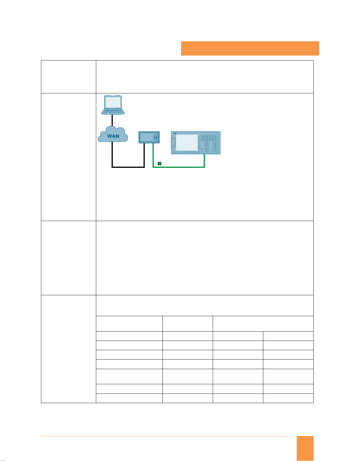
PC/PG
Modem router
Analog ISDN
SINUMERIK 828D
PROFINET
G_NC01_EN_00582
RCS Host remote diagnostics software for connection of a modem router to the X127 is solely
necessary in case of connection via Modem router. It is possible to monitor and influence a control
from a remote PC. The remote viewer gets the same display of SINUMERIK 828. A modem router is
required for connecting SINUMERIK 828 to a viewer on a telephone line /internet
Remote diagnosis has the following services:
Direct access to SINUMERIK 828
Data exchange (file transfer)
The following extended technologies are only available in SINUMERIK 828D BASIC.
Asymmetric grooves (only turning)
Drill and thread milling
Thread milling
Multi-edge milling
Engraving
Extended stock removal along contour with segmentation of blank (only turning)
Contour grooving and plunge turning (only turning)
Milling of contour pockets and spigots (with up to 12 islands)
Position pattern - hide position
Asymmetrically turn a shoulder
DIN thread undercut
This option must be selected if the required number of interpolating axes/spindles is more than the
basic quantity of axes/spindles. The basic quantity of axes offered by panel processing units/
SINUMERIK 828D family is given in the table below:
SINUMERIK 828D
SINUMERIK 828D
BASIC
PPU 24x.3 PPU 26x.3 PPU 28x.3
Basic quantity of axes
Turning
Milling
Max. possible quantity of
axes/spindles
Turning
Milling
3 3 3
4 4 4
5 6 8
5 6 6
Siemens NC 82 · 2014
1
Page 2

Glossary
© Siemens AG 2014
Functions and terms
SINUMERIK 828
Contour handwheel
Option M08
Article No.:
6FC5800-0AM08-0YB0
Evaluation of internal drive variables
Option S53
Article No.:
6FC5800-0AS53-0YB0
(6FC5800-0AM41-0YB0
for V 2.x)
Extended operator functions
Option P16
Article No.:
6FC5800-0AP16-0YB0
When the contour handwheel function is activated, the handwheel has a velocity-generating
effect in AUTOMATIC and MDI modes on all programmed traversing movements of the path and
synchronized axes.
A feedrate specified via the CNC program becomes ineffective and a programmed velocity profile is
no longer valid. The feedrate, in mm/min, results from the handwheel pulses as based on pulse
weighting (machine data) and the active increment. The handwheel's direction of rotation
determines the direction of travel:
Clockwise:
in the programmed direction of travel (even beyond block boundaries)
Counter-clockwise:
against the programmed direction of travel (continuation beyond the start of the block is
prevented).
The following real-time drive variables can be accessed/evaluated in part program:
$AA_LOAD drive capacity utilization in Percentage (%)
$AA_POWER drive active power in Watts (W)
$AA_TORQUE drive torque set point in Newton meters (Nm)
$AA_CURR actual axis/spindle current in Ampere (A)
These variables can be used along with synchronized options
These variables can be also read through PLC interface, NC variables DB1200.DBxxxxx. For the PLC
purpose, evaluation of internal drives is standard.
Application examples :
Evaluation of these drive variables also permits machines and tools to be protected from
overloading, as well as shorter machining times and an improved surface quality for the
workpieces to be achieved. Evaluation of internal drive variables is a prerequisite for implementing
adaptive control (AC).
Adaptive control can be parameterized within the part program as follows:
Additive influence: The programmed feed value is corrected by adding.
Multiplicative influence: The feed value is multiplied by a factor (override).
Number of levels for skip blocks 10 (default value 2)
Teach-in function
Backup workpiece setup data
Display active synchronized actions
DRF offset
Overstoring
Extended block search (program/search pointer, level up/down, interrupt position)
Manual workpiece measurement: advanced strategies for part probing
Additional measuring version beyond standard scope
(standard scope workpiece zero: Set edge, align edge, right-angled corner, 1 hole, and 1 circular
spigot.
Expansion of the measurement window via combo box)
Load/save MDI program
2
Siemens NC 82 · 2014
Page 3
© Siemens AG 2014
Extended stop and
retract ESR, driveautonomous
Option M60
Article No.:
6FC5800-0AM60-0YB0
Generic coupling Basic: CP-Basic
Option M72
Article No.:
6FC5800-0AM72-0YB0
Glossary
Functions and terms
SINUMERIK 828
Power failure
retraction
Work-piece
G_NC01_EN_00583
A safe position is assumed from the machining level without any collision between tool and
workpiece.
As well as the drive-autonomous stop and retract function, the CNC-controlled stop and retract
functionality is also provided. To permit gentle interpolated retraction on the path or contour, the
path interpolation can be processed further for a definable period following the triggering event.
The retraction axes are subsequently traversed in synchronism to an absolute or incremental
position as programmed.
These functions are primarily used for gearing and grinding technologies.
n
2
n
1
G_NC01_EN_00575
Spindle 1 Spindle 2
Up to 4 × simple coupled motion and
Up to 1 × synchronous spindles/multi-edge turning or master value coupling/curve table
interpolation or axial coupling in the machine coordinate system
Application example:
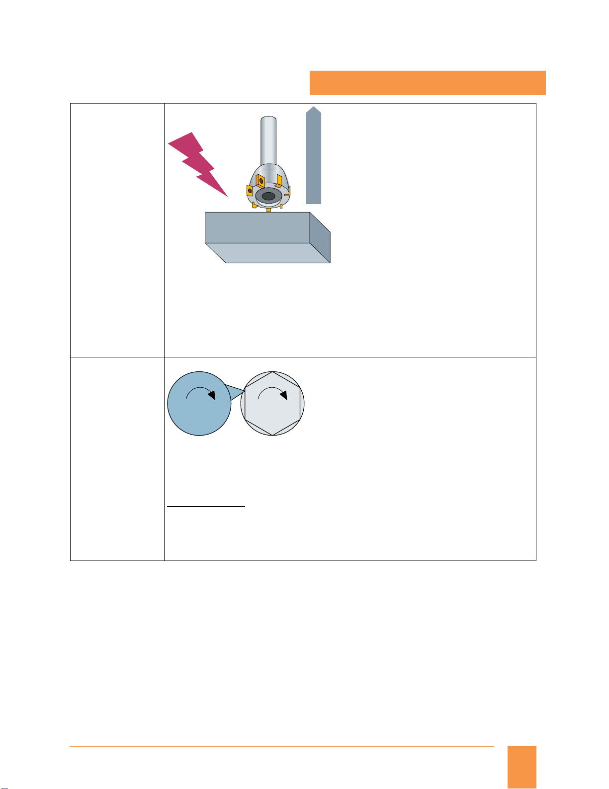
Multi-edge machining (polygonal turning)
The synchronous spindle function provides the basis for multi-edge machining through
specification of an integer gear ratio between leading spindle and following spindle. In the picture
above, spindle 2 contains the job and spindle 1 has the cutting tool. Both the spindles are
synchronized and run at a ratio (e.g.: 1:6), in order to get polygon shape on the job.
Siemens NC 82 · 2014
3
Page 4
Glossary
© Siemens AG 2014
Functions and terms
SINUMERIK 828
Generic coupling Comfort: CP-Comfort
Option M73
Article No.:
6FC5800-0AM73-0YB0
Generic coupling Static: CP-Static
Option M75
Article No.:
6FC5800-0AM75-0YB0
Up to 4 × simple coupled motion and
Up to 4 × synchronous spindle/multi-edge turning and/or master value coupling/curve table
interpolation and/or axial coupling in the machine coordinate system
Also:
1 × electronic gear for up to 3 leading axes is possible (without curve table interpolation and
without cascading)
Application example:
This option is suitable for the hobbing process. Gear hobbing machines are machines which have a
rotating multiple-tooth cutting tool to produce teeth on helical gears, worm gears, cycloid gears,
etc.
When two axes (e.g. tool axes) with different ratio must be coupled on to third axes (e.g. blank
axes).
G_NC01_EN_00576
Spindle 1 Spindle 2
n
n
1
2
One simple synchronous spindle (with coupling ratio 1:1, no multi-edge machining)
Application example:
Reverse side machining in a double-spindle lathe with on-the-fly transfer of the work piece from
the position-synchronous LS to the FS (or vice versa), without having to decelerate to standstill.
4
Siemens NC 82 · 2014
Page 5
Glossary
© Siemens AG 2014
Functions and terms
SINUMERIK 828
Inclined axis
Option M28
Article No.:
6FC5800-0AM28-0YB0
Leadscrew error
compensation,
bidirectional:
Bidirectional
threaded spindle
error compensation
Option M54
Article No.:
6FC5800-0AM54-0YB0
JOG "X"
JOG "U"
X
G07 X70 Z40 F4000
100
70
W
0
Oblique plunge-cut grinding: machine with non-Cartesian X axis (U)
G05 X70 F100
40
U
Z
G_NC01_XX_00121
The Inclined axis function is used for fixed-angle interpolation using an oblique infeed axis (used
primarily in conjunction with cylindrical grinding machines). The axes are programmed and
displayed in the Cartesian coordinate system.
Tool offsets and work offsets are also entered in the Cartesian system and transformed to the real
machine axes.
For oblique plunge-cutting with G05, it is necessary to program the start position with G07.
Bi-directional compensation
G_NC01_EN_00585
Bidirectional compensation is an expansion to the leadscrew error compensation function (LEC) or
the measuring system error compensation function (MSEC). By contrast to LEC and MSEC,
bidirectional compensation works in both directions.
The option supports price sensitive front-face and peripheral side machining applications on lathes
without a mechanical Y axis.
Siemens NC 82 · 2014
5
Page 6
Glossary
© Siemens AG 2014
Functions and terms
SINUMERIK 828
Machining step programming ShopTurn/ShopMill
Option P17
Article No.:
6FC5800-0AP17-0YB0
Master-slave for drives, basic
Option S52
Article No.:
6FC5800-0AS52-0YB0
(6FC5800-0AM03-0YB0
for V 2.x)
Measure kinematics
Option P18
Article No.:
6FC5800-0AP18-0YB0
Processes such as drilling, centering, plunging or pocket milling are represented as machining
steps in a simple and clear manner. In this way, part programs – even for complex machining
operations – are very compact and easily read. Associated sequences are automatically interlinked
and can be assigned any position patterns. This unique programming convenience allows you to
achieve the shortest programming times even for highly demanding machining tasks.
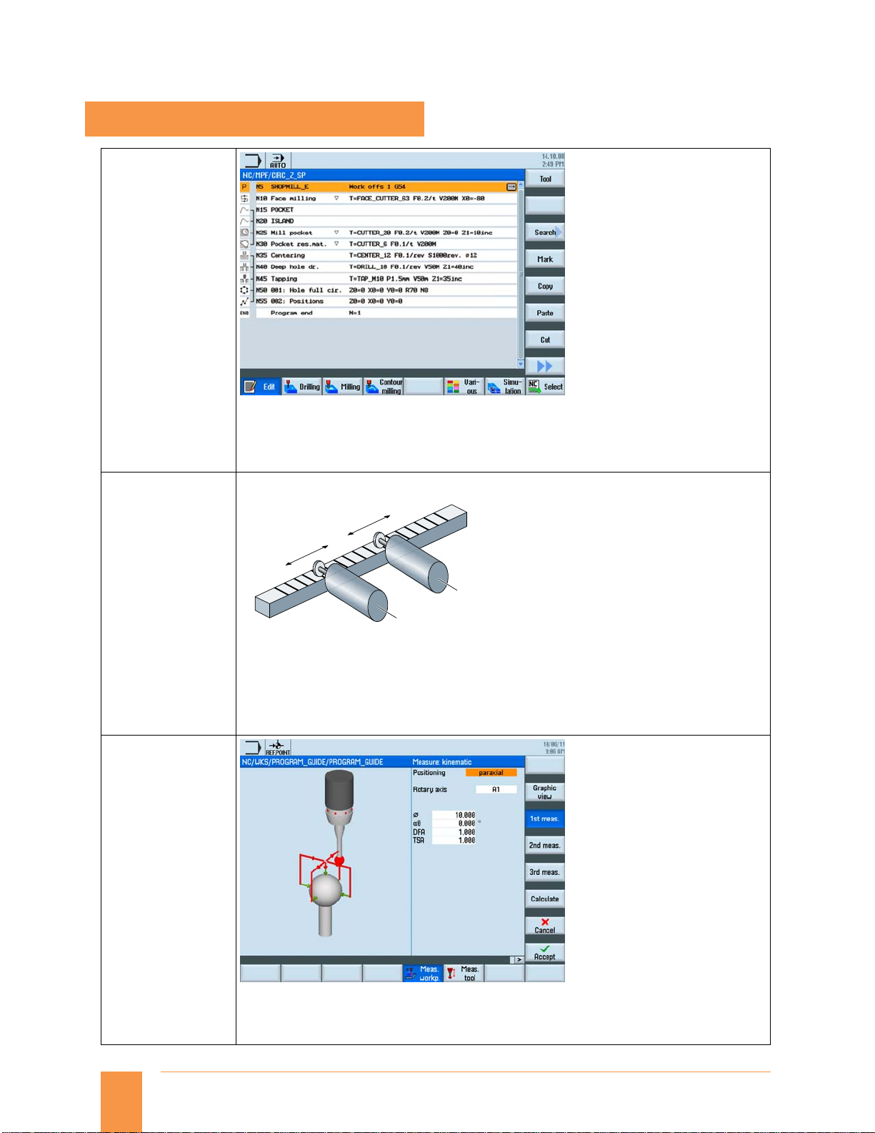
Coupling: "OPEN"
Motion: A xis 2
Motion: A xis 1
Axis 1
G_NC01_EN_00586
Axis 2
A master-slave coupling is a speed setpoint coupling between a master and slave axis performed at
the position controller level – with and without torque equalization control. The coupling can be
permanently closed.
Possible applications of a master-slave coupling include:
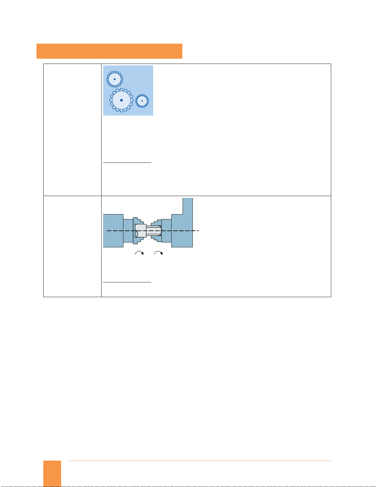
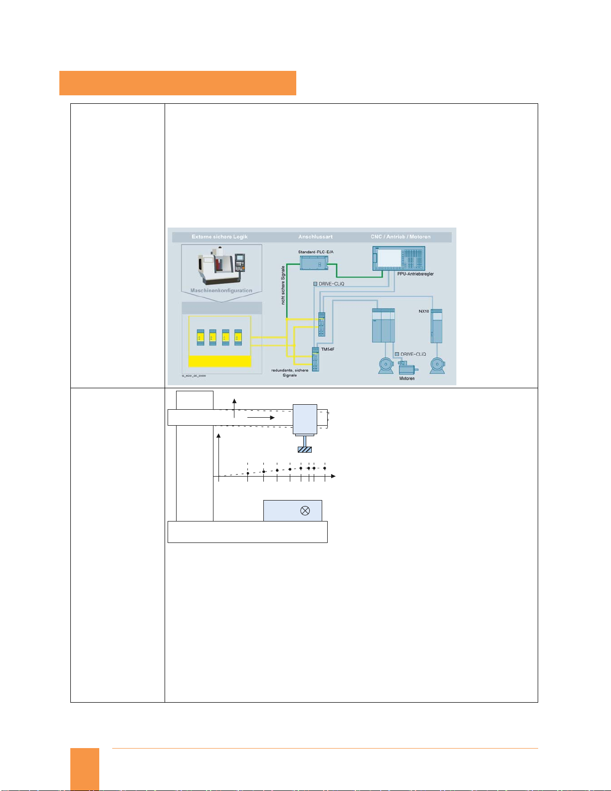
Increase the power for mechanically coupled drives
Compensating gear and gear tooth flank play by entering a pre-tensioning torque
6
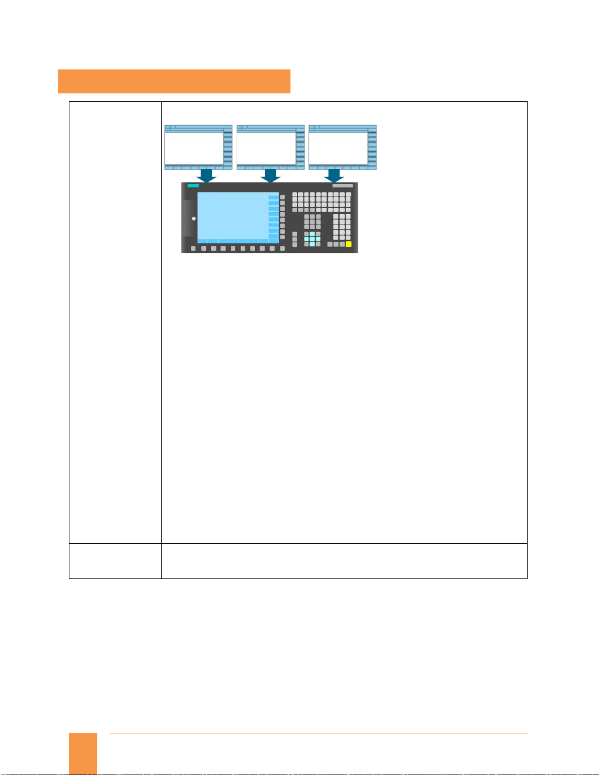
This option is able to determine the parameters of kinematic transformations of the digitally or
manually alignable rotary axes quickly and automatically. The function is ideal for initial startup,
because a dimensioned drawing of the machine is not required. The function can also be used for
regular checking of the production process, when high precision is required.
Siemens NC 82 · 2014
Page 7

Glossary
© Siemens AG 2014
Functions and terms
SINUMERIK 828
Measuring cycles for drilling/milling and turning
Option
Article No.:
6FC5800-0AP28-0YB0
Measuring cycles are subroutines designed to perform specific measurement tasks. They can be
adapted to specific requirements via parameter settings.
Workpiece measurements
Example: Milling machine
Z
Y
W
G_NC01_EN_00587
X
Workpiece measurement
A measuring probe is moved up to the clamped workpiece in the same way as a tool and measured
values are acquired. The flexibility of measuring cycles makes it possible to perform nearly all
measurements required on a milling or turning machine. An automatic tool offset or zero offset
correction can be applied to the workpiece measurement result.
Too l mea s urem e n ts
Measure turning tool length 1, length 2
Multiple clamping of
various workpieces
(included in
ShopMill/ShopTurn)
Option P17
Article No.:
6FC5800-0AP17-0YB0
X
Z
Tool measurement
G_NC01_EN_00588
The selected tool is moved up to the probe and the measured values are acquired. The probe is
either in a fixed position or is swung into the working area with a mechanism. The tool geometry
measured is entered in the appropriate tool offset data set.
G_NC02_XX_00381
Several identical workpieces can be clamped onto the machine table. With the multiple clamping
function, an entire program is generated from the graphic program of the relevant single
machining operation. The machining steps are sorted in this program so that the number of tool
changes (and thus idle times) is reduced to a minimum.
This function allows different workpieces to be finished on multiple vises or gripping yokes, while
saving time.
Note:
Since SW V4.5 multiple clamping (6FC5800-0AP14-0YB0) is part of ShopMill/ShopTurn
(6FC5800-0AP17-0YB0).
Siemens NC 82 · 2014
7
Page 8

Glossary
g
© Siemens AG 2014
Functions and terms
SINUMERIK 828
Pair of synchronized axes (gantry axes), basic
Option S51
Article No.:
6FC5800-0AS51-0YB0
(Option M02
Article No.:
6FC5800-0AM02-0YB0
for V 2.x)
Positioning axis/auxiliary spindle, each additional
Option
Article No.:
6FC5800-0AC30-0YB0
(6FC5800-0AB00-0YB0
for V 2.x)
Program management on network drive
Option
Article No.:
6FC5800-0AP01-0YB0
Y
Z
X
X1
G_NC01_XX_00112
Gantry axes (pair of synchronous axes X/X1)
The gantry axes function can be used to traverse mechanically-coupled axes simultaneously
without mechanical offset. The actual values are continuously compared and even the smallest
deviations corrected.
During both operation and programming, the axes defined in a gantry grouping are treated like
one machine axis.
A maximum of one gantry pair is possible with this option.
This is an option for any positioning axis that is required in addition to the basic quantity of
axes/spindles. The total number of axes/spindles is limited by the maximum number of axes
offered by the SINUMERIK 828D family.
Please refer to the table below for the maximum number of axes/spindles offered by all the PPU
variants.
→ Axis/spindle, each additional
Application examples:
For applications like magazine of ATC, pallet, auxiliary spindle (without tapping/threading), or any
positionin
axis.
8
Allows execution of part-programs from external server by Windows Share/FTP client
Max 4 additional drives can be defined on Ethernet
Part program execution can be done from any of these network drives
Program/workpiece data management can also be done
Siemens NC 82 · 2014
Page 9

© Siemens AG 2014
Replacement tools for tool management
Option M78
Article No.:
6FC5800-0AM78-0YB0
Glossary
Functions and terms
SINUMERIK 828
Residual material detection
Option P13
Article No.:
6FC5800-0AP13-0YB0
Option for defining replacement sister-tool. Tool life is monitored on the basis of machining time
or number of components. If the tool life is completed (or if the tool finishes number of
components) the defined sister-tool is automatically selected.
Y
20
10
0
-10
Milling
-20
-30
0102030405060708090100110
Turning
Pre-machining
with large cutter
X
Stock removal
longitudinal
with blank
segmentation
Contour ranges which cannot be machined with large tools are automatically recognized by the
cycle for contour pockets or the stock removal cycle. The operator can rework these regions using
a smaller tool.
Contour turning offers:
Contour/axis-parallel cutting with residual material detection
Contour cutting with residual material detection
Plunge-turning with residual material detection
Contour milling offers:
Contour spigot with residual material detection
Contour pocket with residual material detection
Machining, e.g. in the steps: centering, predrilling, rough machining and rough machining
residual material, smoothing, edge/base, gripping
Y
20
10
0
-10
MillingTurning
-20
-30
0102030405060708090100110
Cutting residual
material with
small cutter
X
Cutting residual
material with
contour grooving
G_NC01_EN_00589
Siemens NC 82 · 2014
9
Page 10
Glossary
© Siemens AG 2014
Functions and terms
SINUMERIK 828
Safety Integrated Extended Functions
Option C50
Article No.:
6FC5800-0AC50-0YB0
(6SL3074-0AA10-0AA0
for V 2.x)
Sag compensation, multi-dimensional
Option M55
Article No.:
6FC5800-0AM55-0YB0
SINUMERIK 828 has as standard the following Safety Integrated functions:
Safe Torque Off (STO)
Safe Brake Control (SBS)
Safe Stop 1 (SS1)
Option for extended Safety Integrated Functions for one CNC axis
Safe Operating Stop (SOS)
Safe Stop 2 (SS2)
Safely Limited Speed (SLS)
Safe Speed Monitor (SSM)
Safe Acceleration Monitor (SAM)
Safe Direction
SINAMICS S120 Terminal Module Cabinet TM54F is required to configure the above options.
Z
-Y
Z
10
Sag compensation
Multi-dimensional compensation is also possible for the effects of physical influences and
manufacturing tolerances such as sag or leadscrew pitch errors. The compensation tables can be
switched from the PLC.
When the reference axis and the compensating axis are identical, leadscrew pitch errors can be
compensated. By transferring weighting factors (PLC interface), stored compensating
characteristics can be adapted to different conditions (e.g.: tools).
The most important features of interpolation and compensation using tables are as follows:
Independent error characteristics can be defined, in number twice the maximum number of axes
Freely selectable compensating positions, the number of which is configurable (dependent on
the configuration of CNC user memory)
Interpolating inclusion of the compensation values
Weighting factor for compensation of tool weights
Reference axis and compensating axis are selectable
Siemens NC 82 · 2014
-Y
X
G_NC01_XX_00108
Page 11

© Siemens AG 2014
Simultaneous recording
Option P22
Article No.:
6FC5800-0AP22-0YB0
Glossary
Functions and terms
SINUMERIK 828
With real-time simulation, the simulation can be viewed in the ‘machine’ screen of control the
when the part program is running in automatic mode. The tool movement in the simulation screen
is dependent on the actual tool (axes) movement and gives an accurate view of the machining
going on.
Note:
Activate simultaneous recording prior to CNC start in order to avoid incomplete displays.
Siemens NC 82 · 2014
11
Page 12
Glossary
© Siemens AG 2014
Functions and terms
SINUMERIK 828
SINUMERIK Integrate Run MyScreens
Option P64
Article No.:
6FC5800-0AP64-0YB0
SINUMERIK Operate Runtime license OA Easy Screen
EASY SCREEN
Own operator
areas
Easy Screen
The Easy Screen functionality allows SINUMERIK users to design their own user interfaces for the
purpose of displaying either machine-manufacturer or end-user-specific functional expansions or
simply their own screen form layouts.
User interfaces configured by Siemens or other machine manufacturers can be modified or
replaced. This function is implemented via an integrated interpreter and via configuring files
containing the description of the user interface.
The screen forms can be designed directly on the control itself. A graphic tool is required to create
graphics and pictures. Part programs can be processed with newly created user interfaces.
Configuring examples for new screen forms, which can also be used as the basis for the user's own
new screen forms, can be found in the supplied toolbox.
The following functions can be implemented using Easy Screen:
Display screen forms and provide softkeys, variables, tables, texts, help texts, graphics, and
help screens
Start actions when screen forms are displayed and exited, press softkeys, and enter values
(variables)
Dynamic restructuring of screen forms, including changing softkeys, designing arrays and
displaying, replacing and deleting display texts and graphics
Read and write variables, combine with mathematical, comparative or logical operators
Execute subprograms, file functions, program instance services (PI services) or external
functions (HMI-Advanced)
Enable data exchange between screen forms
Easy Screen is configured using ASCII files that can be stored on the PCU. Files that contain ASCII
descriptions for the layout of interactive screen forms, softkey functions and display texts and
graphics are interpreted. These configuring files are created with the ASCII editor, taking into
account certain special rules of syntax.
The user interface can be expanded even in the basic version by up to 5 screen forms via
predefined softkeys with the integrated editor.
More than 5 screen forms with Operate Runtime license OA Easy Screen (option P64).
→ SINUMERIK Integrate Run MyScreens
Overlap of
system
screens
Cycle support
screens
G_NC01_EN_00591
12
Siemens NC 82 · 2014
Page 13
Glossary
© Siemens AG 2014
Functions and terms
SINUMERIK 828
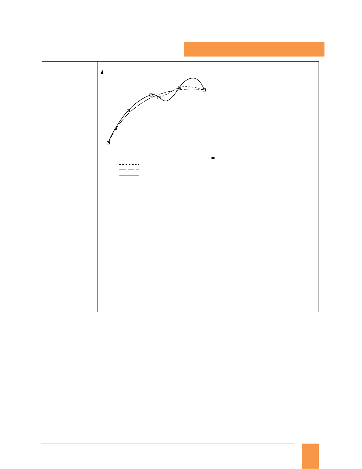
Spline interpolation (A, B and C splines)
Option S16
Article No.:
6FC5800-0AS16-0YB0
P6
P1
A spline
B spline
C spline
P4
P5
P3
P2
P7
G_NC01_EN_00594
Using spline interpolation, it is possible to obtain a very smooth curve from just a few defined
interpolation points along a set contour. The intermediate points are connected by polynomials.
The compressor converts linear motions (e.g.: from CAD) at block transitions to splines of constant
speed (COMPON) or splines of constant acceleration (COMPCURV). This yields soft transitions that
reduce wear on the mechanical parts of the machine tool. However, if the intermediate points are
placed close together, quite sharp edges can also be programmed. Spline interpolation also
considerably reduces the number of program blocks required.
Extremely smooth workpiece surfaces are often very important in mold and tool making, both
optically and technologically, e.g.: for rubber gaskets.
Tool radius compensation is also possible in spline interpolation, as it is in linear or circular
interpolation.
Every polynomial can represent a spline. Only the algorithm determines the type of spline.
A spline is only true to the tangents.
B spline is true to the tangents and the curvature, but does not run through the nodes
(intermediate points).
C spline is true to the tangents and the curvature and runs through the nodes.
With the COMPCAD compressor, smooth curves of this kind can be approximated within the
boundaries of compressor tolerance (parallel tool paths) so that surfaces of a high optical quality
can also be obtained in the case of increased tolerances.
Spline interpolation for 3-axis machining is suitable for simple applications and for the JobShop
area.
Siemens NC 82 · 2014
13
Page 14

Glossary
© Siemens AG 2014
Functions and terms
SINUMERIK 828
TRANSMIT/cylinder surface transformation
Option M27
Article No.:
6FC5800-0AM27-0YB0
X
Y
C
Z
Face machining with TRANSMIT
G_NC01_XX_00127
Y
Y'
Pole
(center)
Workpiece
Tool-center-point path through the pole
Too
l
C
X'
X
Rotary table
G_NC01_en_00128
TRANSMIT is used for milling outside contours on turned parts, e.g.: square parts (linear axis with
rotary axis).
As a result, programs become much simpler and complete machining increases machine
efficiency. Turning and milling can be performed on one machine without rechucking.
3D interpolation with 2 linear axes and one rotary axis is possible. The two linear axes are mutually
perpendicular and the rotary axis lies at right angles to one of the linear axes.
TRANSMIT can be called up in different channels simultaneously. The function can be selected and
deselected with a preparatory function (straight line, helix, polynomial and activating tool radius
compensation) in the part program or MDI.
With TRANSMIT, the area of the transformation pole is reached when the tool center can be
positioned at least to the turning center of the rotary axis entering the transformation.
TRANSMIT through the pole is implemented in different ways:
When traveling through the pole, the rotary axis is turned automatically by 180° when the
turning center is reached and the remaining block is then executed.
When traveling close by the pole, the control automatically reduces the feedrate and the path
acceleration.
If the path contains a corner in the pole, the position jump in the rotary axis is compensated by
the control through automatic block insertion.
Cylinder surface transformation is used on turning machines and milling machines, and enables
cylinder surface transformation, e.g.: for turned parts.
The TRACYL cylinder surface transformation can be used to manufacture grooves of any shape on
the surface of cylindrical bodies with or without groove side offset. The shape of the grooves is
programmed in reference to the plane cylinder surface processed.
14
Siemens NC 82 · 2014
Page 15

Glossary
© Siemens AG 2014
Functions and terms
SINUMERIK 828
TRANSMIT/cylinder surface transformation without Y axis
Option S50
Article No.:
6FC5800-0AS50-0YB0
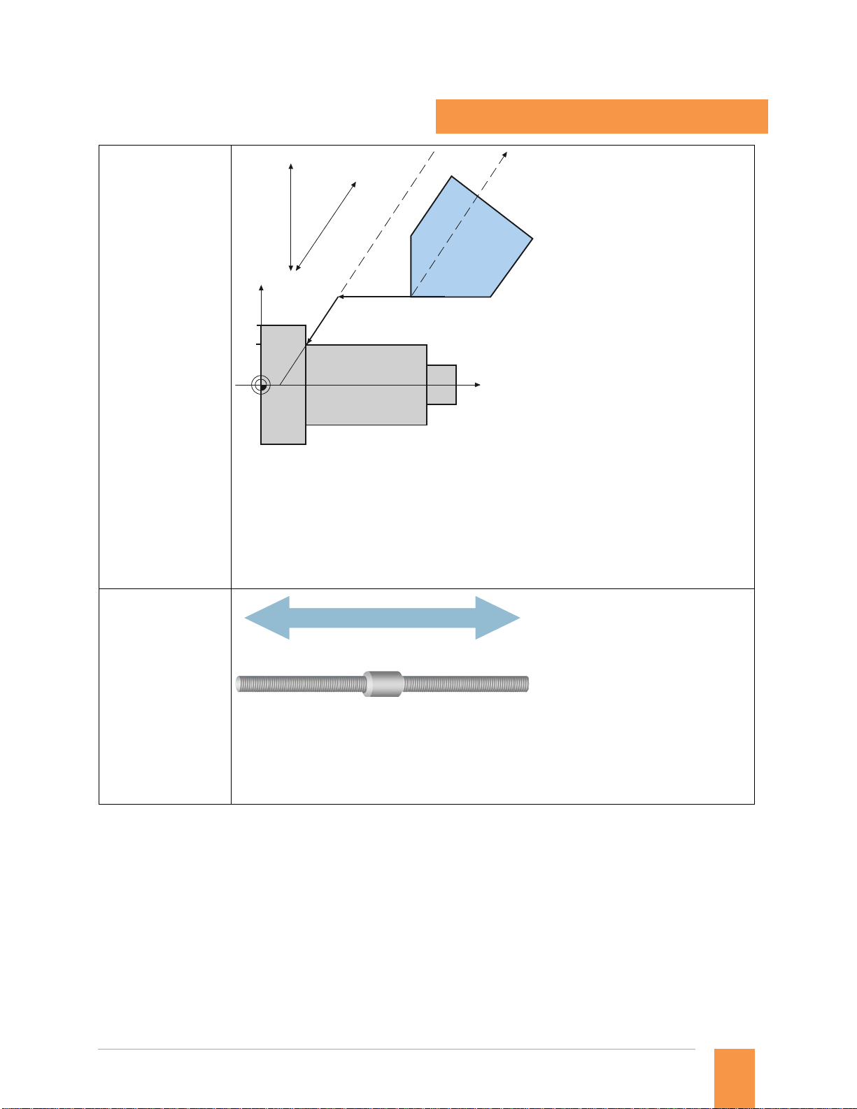
Travel to fixed stop with Force Control
Option M01
Article No.:
6FC5800-0AM01-0YB0
X
C
G_NC01_EN_00592
This option – similarly to TRANSMIT and cylinder surface transformation on a cylindrical
component – enables to perform front face machining using Cartesian coordinate system and
TRACYIL to perform machining on the surface of the cylinder, when physically Y axis is not
required.
Actual position after
"travel to fixed stop"
G_NC01_EN_00593
Fixed stop
monitoring
windows
Program end position Start position
The extended travel to fixed stop function can be used to adapt torque or force on a modal or nonmodal basis; travel with limited torque/limited force (force control, FOC) can be initiated, or
synchronized actions can be used at any time to program traversing functions.
Application example:
Servo tail stock function with force control requirement. This also can be combined along with
synchronized actions.
Siemens NC 82 · 2014
15
 Loading...