

Page 1
!»
1
Is
•I
lit
ei
biii
te
i
'‘ill
tÿr
i
SINUMERIK
Software
Operating
Version
Guide
805SM-TW
4
Edition
02.94
•
User
Documentation
Page 2
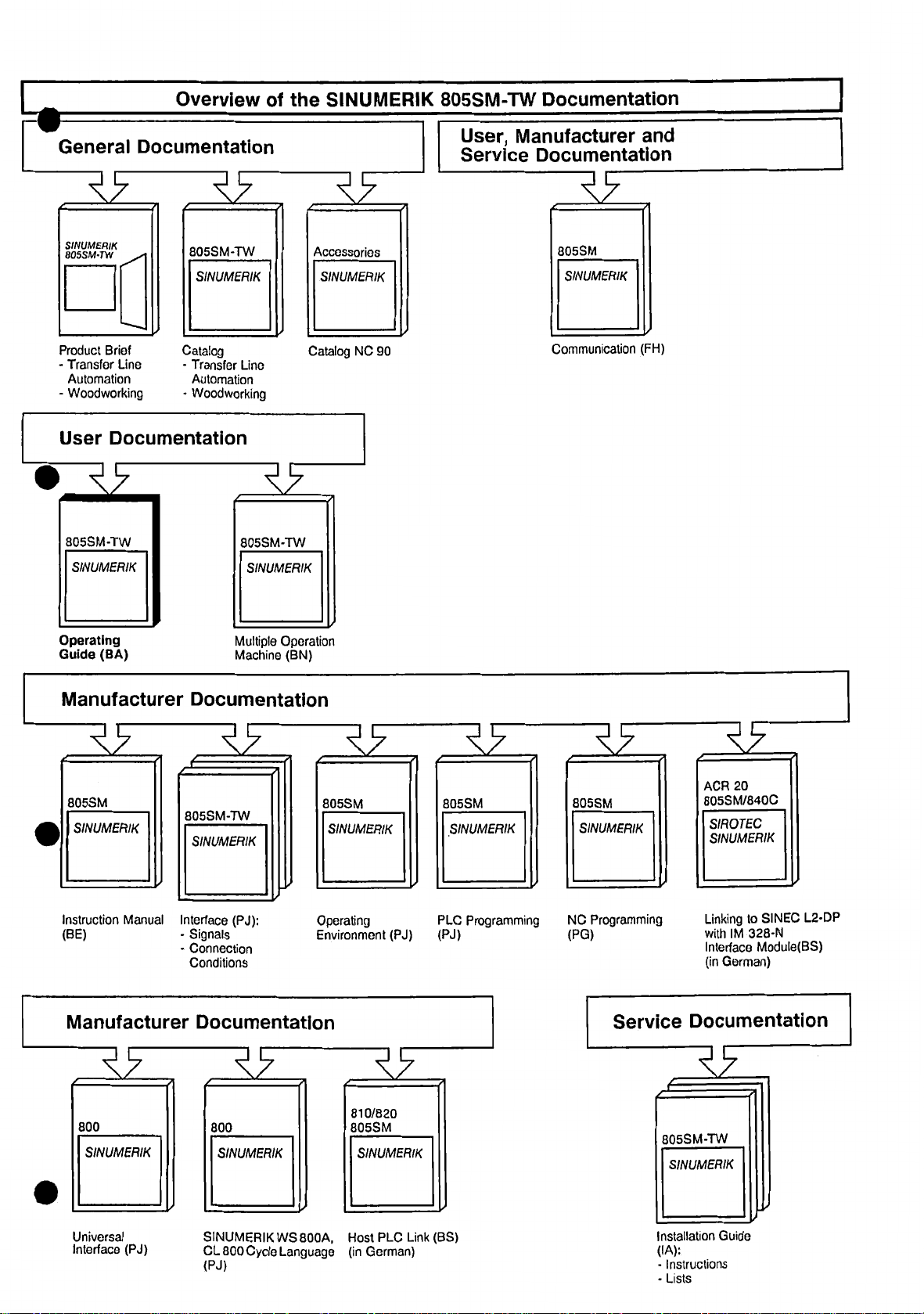
Overview
of
SINUMERIK
the
805SM-TW
Documentation
General
19
SINUMERIK
BOSSM’TW
Product
Transfer
-
Automation
Woodworking
-
User
Wÿ9
805SM-TW
SINUMERIK
Documentation
19
805SM-TW
SINUMERIK
Brief
Line
Documentation
Catalog
Transfer
-
Automation
•
Woodworking
Lino
<9
805SM-TW
SINUMERIK
RF
Accessories
SINUMERIK
Catalog
NC
90
User,
Service
Manufacturer
Documentation
19
805SM
SINUMERIK
Communication
and
(FH)
Operating
(BA)
Guide
Manufacturer
805SM
SINUMERIK
Instruction
(BE)
Manual
Manufacturer
Multiple
Operation
Machine
(BN)
Documentation
19
805SM-TW
SINUMERIK
Interface
-
-
(PJ):
Signals
Connection
Conditions
Documentation
805SM
SINUMERIK
Operating
Environment
19
(PJ)
\9
805SM
SINUMERIK
Programming
PLC
(PJ)
<9
805SM
SINUMERIK
Programming
NC
(PG)
Service
ACR
20
805SM/840C
SIROTEC
SINUMERIK
Linking
IM
with
Interfaco
German)
(in
to
328-N
Module(BS)
SINEC
L2-DP
Documentation
19
800
SINUMERIK
Universal
Interface
(PJ)
800
SINUMERIK
SINUMERIK
Cycle
CL
800
(PJ)
800A,
WS
Language
810/820
805SM
SINUMERIK
PLC
Host
German)
(in
Link
(BS)
805SM-TW
SINUMERIK
Installation
(IA):
Instructions
-
Lists
-
Guide
Page 3
SINUMERIK
805SM-TW
Software
Operating
User
Documentation
Guide
Version
4
Valid
for:
Control
SINUMERIK
Edition
02.94
805SM-TW
Software
Version
4
3
and
Page 4
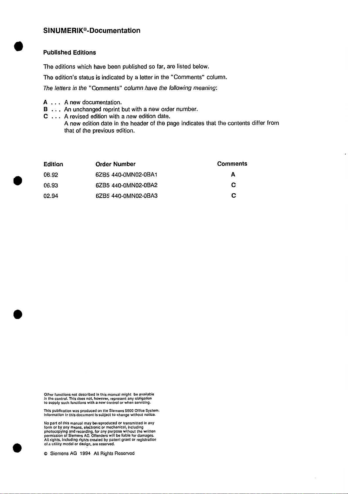
SINUMERIK®-Documentation
Published
The
editions
The
edition’s
The
lettersinthe
A
...
A
B
C
...
.
.
An
.
A
A
that
Edition
06.92
06.93
02.94
Editions
which
have
is
status
"Comments"
new
documentation.
unchanged
revised
new
edition
of
the
edition
previous
Order
6ZB5
6ZB5
6ZB5
published
been
a
indicated
by
column
reprint
with
date
in
but
a
the
with
new
header
edition.
Number
440-0MN02-0BA1
440-0MN02-0BA2
440-0MN02-0BA3
so
letter
have
a
new
edition
of
far,
in
the
date.
the
are
the
order
page
below.
listed
"Comments"
following
meaning:
number.
indicates
column.
the
that
Comments
contents
A
C
C
differ
from
functions
Other
the
control.
In
supply
such
to
This
publication
Information
No
form
photocopying
permission
All
of
©
of
part
or
by
including
rights,
utility
a
Siemens
this
any
model
not
This
functions
this
in
manual
means,
and
of
Siemens
AG
described
does
produced
was
document
recording,
rights
design,
or
1994
in
not,
however,
a
with
is
be
may
electronic
for
AG.
Offenders
created
ore
All
manual
this
represent
now
control
Siemens
on
the
subject
to
reproduced
mechanical,
or
any
purpose
will
patent
by
reserved.
Rights
miQht
any
when
or
5800
change
without
or
transmitted
including
without
for
be
liable
or
grant
Reserved
available
bo
obligation
servicing.
Office
notice.
in
written
the
damages.
registration
System.
any
Page 5
Preface
Notes
»
This
manual
machine
SINUMERIK
•
•
•
•
The
•
•
In
They
For
The
The
technology.
General
User
Documentation
Manufacturer
Service
User
Documentation
Operating
WOODSTEP
addition
informationonSiemens
to
cover
chapters
Chapter
for
is
intended
805SM-TW
Documentation
Documentation
Manual
Programming
this,
there
topics
to
1
1:
the
Reader
machine
the
for
Documentation
Documentation
consists
are
SINUMERIK
Universal
as
such
Manuals,
3
familiarize
will
General
Information,
'
of
the
Manual
Interface,
please
you
user.
It
available
is
following
manuals
Measuring
contact
the
with
explains:
describes
which
the
in
four
manuals:
apply
Cycles,
your
local
fundamental
control
groups:
all
to
Cycle
Siemens
features
multiple
for
SINUMERIK
the
Language
sales
the
of
operations
CL800,
office.
control:
controls.
etc.
the
•
how
•
The
Chapter
the
•
the
•
The
Chapter
how
•
the
•
The
chapters
during
trol
The
Chapter
how
•
diagnostics.
The
Chapter
how
•
how
•
components
switch
to
control
control
to
select
structure
the
to
enter
to
operate
to
operate
on
2:
elements
and
3:
modes
of
4
and
machining
4:
data
5:
which
the
off
and
Control
and
menus,
data
Modes
of
the
basic
5
show
process:
Input
of
programs,
for
Operating
control
the
the
control
SINUMERIK
SINUMERIK
the
Elements
function,
their
their
Operation,
of
operation,
screens
you
how
informs:
Data,
parameters,
Sequences,
before,
during
805SM-TW
805SM-TW.
Operating
and
hierarchy
explains:
the
different
in
to
enter
describes:
during,
machining
the
and
data,
tool
and
built
is
Areas,
elements.
modes.
prepare
offsets,
program
after
process.
of,
informs
control
the
zero
input,
about:
offsets,
and
data
operate
transfer,
the
con¬
and
Page 6
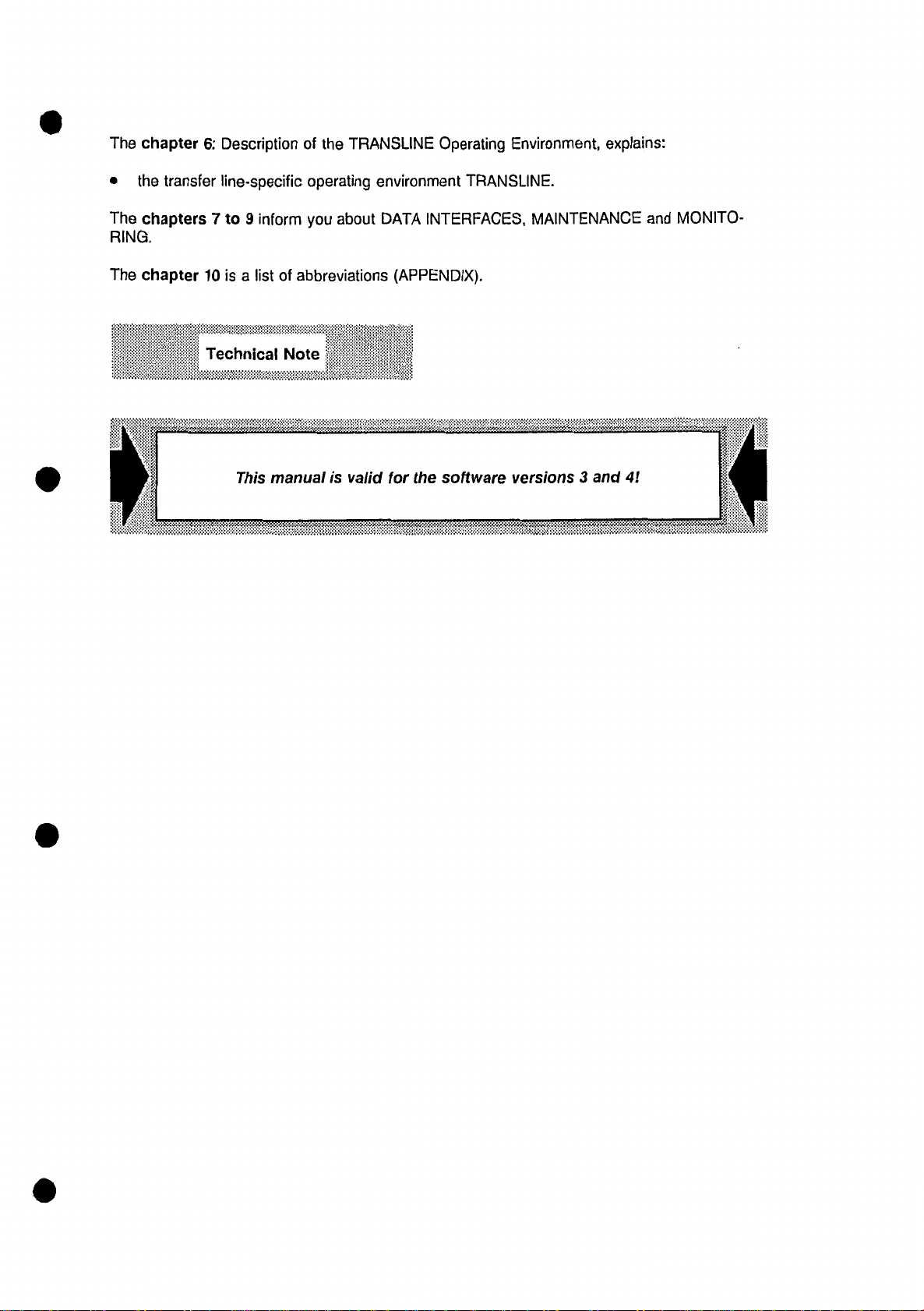
The
chapter
6:
Description
of
the
TRANSLINE
Operating
Environment,
explains:
the
•
The
chapters
RING.
chapter
The
transfer
10
Technical
line-specific
7
9
to
inform
isalist
This
manual
operating
about
you
abbreviations
of
Note
is
valid
environment
INTERFACES,
DATA
(APPENDIX).
the
for
software
TRANSLINE.
MAINTENANCE
versions
3
and
4!
MONITO¬
and
Page 7
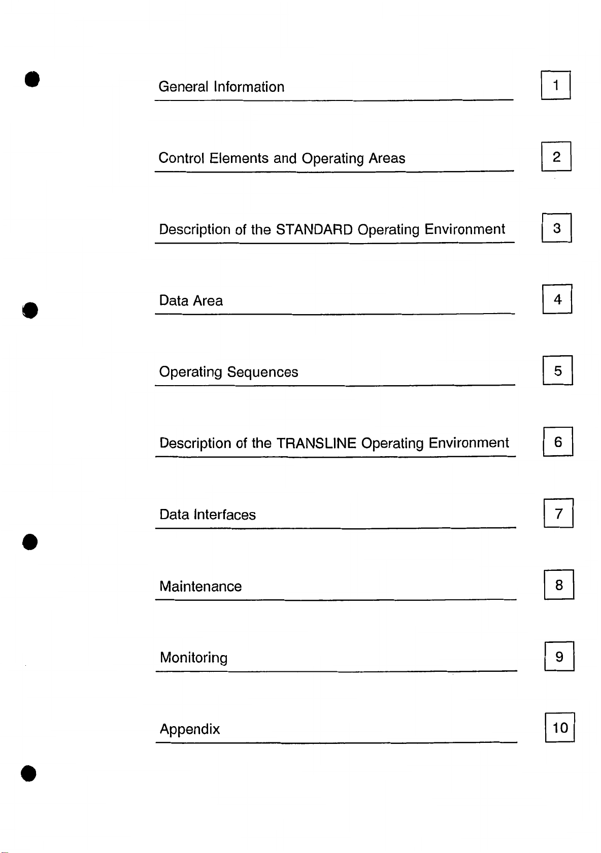
General
Information
Control
Description
Data
Operating
Description
Elements
Area
and
of
the
STANDARD
Sequences
the
of
TRANSLINE
Operating
Operating
Areas
Operating
m
Environment
s
m
0
Environment
0
Data
Maintenance
Monitoring
Appendix
Interfaces
0
0
0
0
Page 8
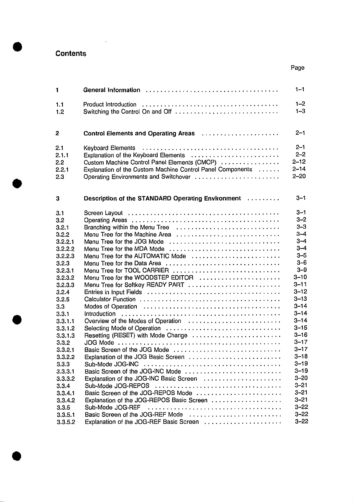
Contents
Page
1
1.1
1.2
2
2.1
2.1.1
2.2
2.2.1
2.3
3
3.1
3.2
3.2.1
3.2.2
3.2.2.
3.2.2.2
2.2.
3.
3.2.3
3.2.3.1
3.
2.3.2
3.2.3.3
3.2.4
3.2.5
3.3
3.3.1
1.1
3.3.
1.2
3.3.
3.3.1.
3.3.2
3.3.2.
3.3.2.2
3.3.3
3.3.3.1
3.3.3.2
3.3.4
3.3.4.1
3.3.4.2
3.3.5
3.3.5.1
3.3.
5.
General
Product
Switching
Control
Keyboard
Explanation
Custom
Explanation
Operating
Description
Screen
Operating
Branching
Menu
1
Menu
Menu
3
Menu
Menu
Menu
Menu
Menu
Entries
Calculator
Modes
Introduction
Overview
Selecting
Resetting
3
JOG
1
Basic
Explanation
Sub-Mode
Basic
Explanation
Sub-Mode
Basic
Explanation
Sub-Mode
Basic
Explanation
2
Information
Introduction
the
Control
Elements
Elements
of
Machine
of
Environments
of
Layout
Areas
within
for
Tree
Tree
for
for
Tree
for
Tree
Tree
for
Tree
for
for
Tree
for
Tree
in
Input
Function
of
Operation
the
of
Mode
(RESET)
Mode
Screen
of
JOG-INC
Screen
of
JOG-REPOS
Screen
of
JOG-REF
Screen
of
On
and
Keyboard
the
Control
Custom
the
STANDARD
the
Menu
the
Machine
the
JOG
the
MDA
the
AUTOMATIC
the
the
Data
TOOL
CARRIER
WOODSTEP
the
Softkey
Fields
Modes
of
Operation
with
of
the
JOG
the
JOG
JOG-INC
the
of
JOG-INC
the
of
JOG-REPOS
the
JOG-REPOS
the
the
of
JOG-REF
JOG-REF
the
and
Off
Operating
Elements
Panel
Machine
and
Switchover
Tree
Area
Mode
Mode
Area
READY
Operation
of
Mode
Change
Mode
Screen
Basic
Mode
Basic
Basic
Areas
Elements
Control
Operating
Mode
EDITOR
PART
.
.
.
...
Screen
Mode
Screen
Basic
Mode
Screen
(CMCP)
Panel
Environment
.
.
.
.
,
.
.
.
...
Components
1-1
1-2
1—3
2-1
2-1
2-2
2-12
2-14
2-20
3-1
3-1
3-2
3-3
3-4
3-4
3-4
3-5
3-6
3-9
3-10
3-11
3-12
3-13
3-14
3-14
3-14
3-15
3-16
3-17
3-17
3-18
3-19
3-19
3-20
3-21
3-21
3-21
3-22
3-22
3-22
Page 9
3.3.6
3.3.6.1
6.2
3.3.
3.3.7
3.3.7.1
3.3.7.2
Mode
MDA
Basic
Screen
Explanation
of
AUTOMATIC
Screen
Basic
Explanation
of
the
of
MDA
the
MDA
Mode
AUTOMATIC
the
of
the
AUTOMATIC
Mode
Basic
Screen
Mode
Basic
.
.
Screen
3-23
3-23
3-23
3-24
.
3-24
3-25
4
4.1
4.2
4.3
4.3.1
4.3.2
4.3.3
4.3.4
4.3.5
4.3.6
4.3.7
4.4
4.4.1
4.4.2
4.4.3
4.4.4
4.5
4.5.1
4.5.2
4.5.3
4.6
4.7
4.8
4.8.1
4.8.2
4.8.3
4.8.4
4.9
4.9.1
4.9.2
4.9.2.1
4.9.2.2
4.9.2.3
4.9.2.4
4.9.2.5
4.9.2.6
4.9.2.7
4.9.2.8
4.9.2.9
4.9.3
Area
Data
Introduction
Screen
Basic
Program
EDITOR
DIN
Program
Part
Copying
Deleting
Renaming
Moving
Reorganizing
Data
R
Setting
Adapted
NO
(NO
Tool
Selecting
Deleting
Description
Zero
Data
Diagnosis
All
PLC
Service
Part
Part
Part
Part
and
Parameters
Parameters
Data
Feedrate
Machine
Bits),
MD
Offset
Tool
and
of
Offset
Transfer
Messages,
Status
Data
Version
LIST
JOB
Introduction
Operating
Basic
INSERT
ALTER
CANCEL
APPEND
START
STOP
NEXT
DELETE
Correcting
the
Screen
JOB
JOB
JOB
JOB
JOB
JOB
Mistakes
of
the
Memory
Program
Program
Program
Program
Program
Part
Data
Values
PLC
Machine
Offset
Altering
the
Tool
NC/PLC
Display
JOB
LIST
LIST
JOB
LIST
Data
Area
Allocation
(NO
Number
Tool
Parameters
Parameters
Alarms,
Memory
MD
(PLC
Data
PLC
Values),
MD)
Messages
NO
Machine
.
Data
Bits
4-1
4-1
4-1
4-2
4-4
4-7
4-8
4-8
4-9
4-9
4-10
4-10
4-11
4-12
4-15
4-15
4-16
4-17
4-17
4-18
4-21
4-24
4-25
4-25
4-26
4-28
4-29
4-30
4-30
4-30
4-30
4-32
4-33
4-34
4-35
4-36
4-37
4-37
4-38
.
4-39
Page 10
5
Operating
Sequences
5-1
5.1
5.2
5.2.1
5.2.2
5.2.3
5.2.4
5.3
5.3.1
5.3.2
5.3.3
5.3.4
5.3.5
5.3.6
5.3.7
5.3.8
5.3.9
5.3.10
5.3.11
5.3.12
5.3.13
5.3.14
Introduction
Preparation
Approaching
Automatic
Tool
Offset,
Program
Machining
Starting
ACTUAL
AUTOMATIC
Program
BLOCK
PROGRAM
Program
Traversing
Traversing
Traversing
MDA
Mode
OVERSTORE
PRESET
CORRECTION
Tool
Tip
Reference
Compensation
Drift
Parameters,
R
Input
Program
Part
PROGRAM
Mode
Interruption
SEARCH
CONTROL
Control
in
JOG
in
JOG-INC
in
JOG-REPOS
Function
Function
BLOCK
Scratch-on
Point
ACTUAL
and
Function
Function
in
AUTOMATIC
Mode
Mode
(Actual
Value
Function
Function
Zero
Mode
Offset,
BLOCK
Mode
Setting)
Setting
Display
Data
5-1
5-1
5-1
5-2
5-3
5-4
5-5
5-5
in
5-6
5-8
5-9
5-11
5-14
5-15
5-16
5-17
5-19
5-20
5-21
5-23
5-24
6
6.1
6.2
6.3
6.4
6.4.1
6.4.2
6.4.2.1
6.4.2.2
6.4.2.3
6.4.3
6.4.3.1
6.4.3.2
7
7.1
7.2
7.3
7.4
7.4.1
7.4.2
7.4.3
7.4.4
7.4.5
7.4.6
Description
Screen
Menu
Switchover
Modes
Layout
Trees
NC-DIRECT
of
Operation
Introduction
TRANSLINE
Basic
Screen
Diagnosis
Functions
AXES/SPINDLE
TRANSLINE
Basic
Screen
PLC
Functions
Interfaces
Data
Introduction
Data
of
Input
Output
Mass
Data
of
Storage
Introduction
Selecting
Displaying
Formatting
Saving,
Modes
the
the
a
Loading
of
Operation
the
of
Mode
TRANSLINE
of
Operation
AUTOMATIC
Mode
of
Operation
SINGLE
through
through
CYCLE
Serial
Serial
OPERATING
Directory
Diskette
and
(DIRECTORY)
(FORMAT)
Deleting
of
the
Operating
AUTOMATIC
TRANSLINE
and
SINGLE
Interface
Interface
MASS
Files
DG-SM
CYCLE
STORAGE
Environment
.
.
.
.
.
Menu
6-1
6-1
6-2
6-3
6-3
6-3
6-3
6-3
6-5
6-6
6-8
6-8
6-9
7-1
7-1
7-2
7-5
7-6
7-6
7-6
7-7
7-10
7-10
7-11
Page 11
7.4.7
1
7.4.7.
7.4.7.2
7.4.8
Data
Saving
Saving
Data
Start-up
Messages
Error
with
and
with
the
Start-up
DG-SM
the
DG-SM
with
the
DG-SM
7-12
7-12
7-14
7-15
8
8.1
8.2
8.3
8.4
9
9.1
9.2
9.3
9.4
10
Maintenance
Printed
Battery
CRT
Circuit
Back
Display
Boards
Up
Cleaning
Monitoring
Introduction
Alarm-Numbers
Display
Alarm
of
List
Alarms
Appendix
for
and
and
Handling
RAM
the
Alarm
Messages
Memory
Groups,
Canceling
Alarms
8—1
8—1
8-2
8-2
8-2
9-1
9-1
9-1
9-3
9-4
10-1
Page 12
06.93
1
General
Information
1
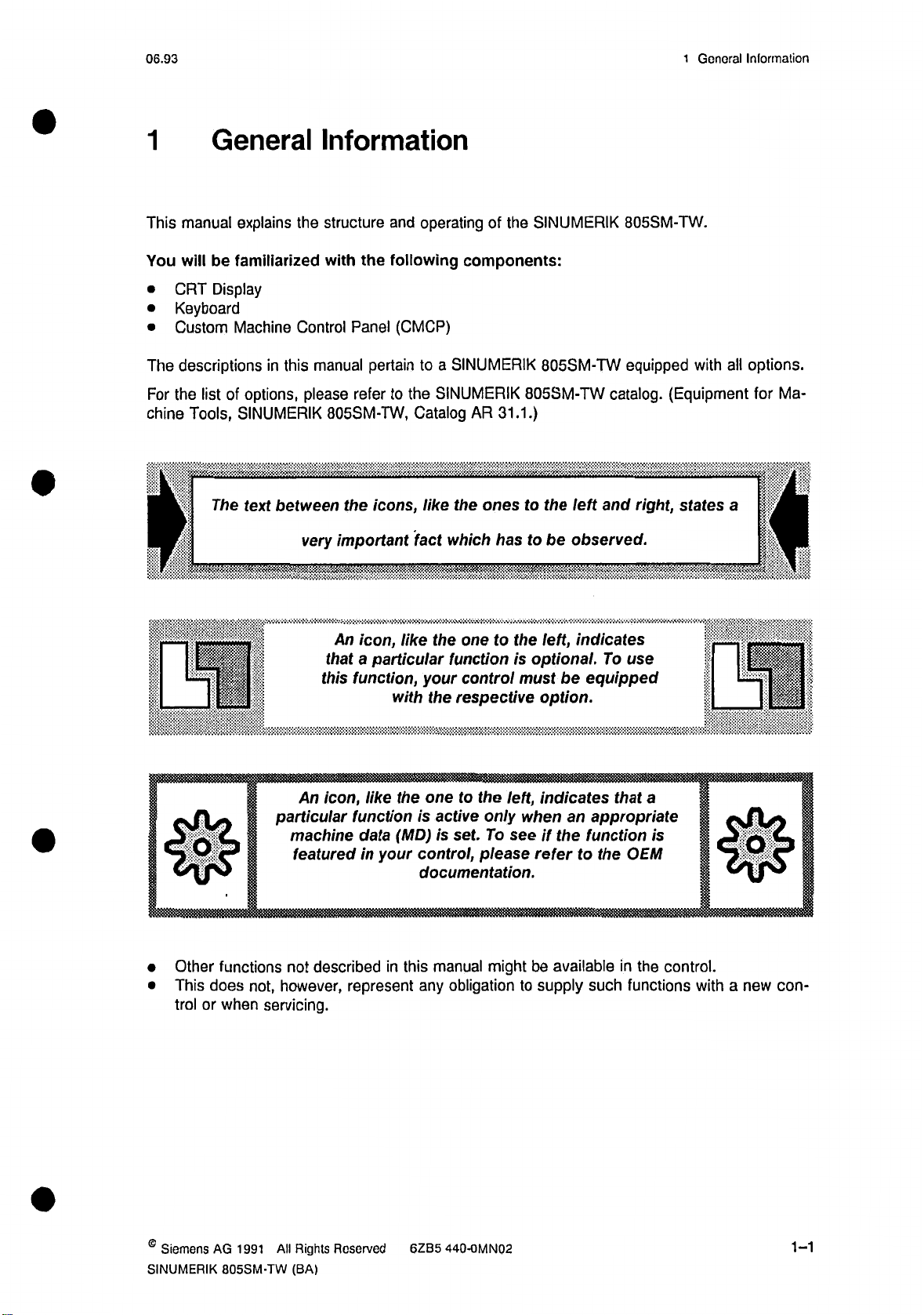
This
manual
You
will
CRT
•
Keyboard
•
Custom
•
descriptions
The
For
the
list
Tools,
chine
4
General
explains
be
familiarized
Display
Machine
options,
of
SINUMERIK
The
text
the
Control
in
this
between
Information
the
Panel
pertain
refer
the
and
following
(CMCP)
to
icons,
the
Catalog
fact
structure
with
manual
please
805SM-TW,
very
important
operating
a
to
SINUMERIK
like
of
components:
SINUMERIK
AR
ones
the
which
SINUMERIK
the
805SM-TW
805SM-TW
31.1.)
to
to
has
the
left
be
observed.
805SM-TW.
equipped
catalog.
right,
and
all
with
(Equipment
states
a
options.
Ma¬
for
\
|
j
4
I
D?
0
Other
This
trol
functions
does
or
when
•
•
particular
machine
not
however,
not,
servicing.
An
that
this
icon,
An
featured
described
like
icon,
particular
a
function,
with
like
the
function
(MD)
data
your
in
in
this
represent
one
the
function
your
control
respective
the
one
to
is
active
is
set.
control,
documentation.
manual
obligation
any
the
to
is
the
left,
only
see
To
please
might
left,
optional.
must
option.
indicates
when
if
the
refer
available
be
supply
to
indicates
be
equipped
an
appropriate
function
the
to
such
use
To
that
OEM
in
functions
a
is
the
control.
with
3
0
a
new
con¬
©
Siemens
SINUMERIK
AG
All
1991
805SM-TW
Rights
(BA)
Roserved
6ZB5
440-OMN02
1-1
Page 13
1
General
1.1
Informations
Product
06.92
Introduction
1.1
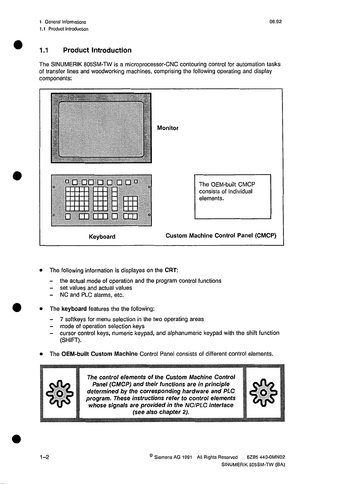
The
of
components:
Product
SINUMERIK
transfer
lines
llllllll
ft!
loop
o
O
I'i
ii
*
maxi
Introduction
805SM-TW
and
woodworking
m
_
is
_
op
O
a
microprocessor-CNC
machines,
comprising
i
Monitor
in
111
II
a
m
m
I
o
&
contouring
following
the
The
consists
elements.
control
OEM-built
for
operating
individual
of
automation
display
and
CMCP
tasks
•
•
•
$
The
-
-
-
The
-
-
-
The
following
the
actual
set
values
NC
keyboard
7
mode
cursor
(SHIFT).
OEM-built
PLC
and
softkeys
of
control
Keyboard
information
mode
of
and
actual
alarms,
features
menu
for
operation
keys,
Custom
The
control
Panel
determined
program
whose
is
displayes
operation
values
etc.
the the
selectioninthe
selection
numeric
Machine
(CMCP)
,
These
signals
and
following:
keys
keypad,
elements
and
by
the
instructions
are
(see
Custom
the
program
two
and
the
of
chapter
CRT:
operating
alphanumeric
Panel
Custom
functions
refer
the
in
on
the
Control
their
corresponding
provided
also
Machine
control
areas
consists
Machine
are
hardware
control
to
NC/PLC
2).
Control
functions
keypad
different
of
Control
principle
in
and
elements
interface
with
control
PLC
Panel
the
shift
(CMCP)
function
elements.
$
1-2
©
Siemens
AG
1991
All
Rights
Reserved
SINUMERIK
6ZB5
440-OMN02
805SM-TW
(BA)
Page 14
06.93
1.2
Switching
1
General
tho
Control
Informations
Off
and
On
1.2
How
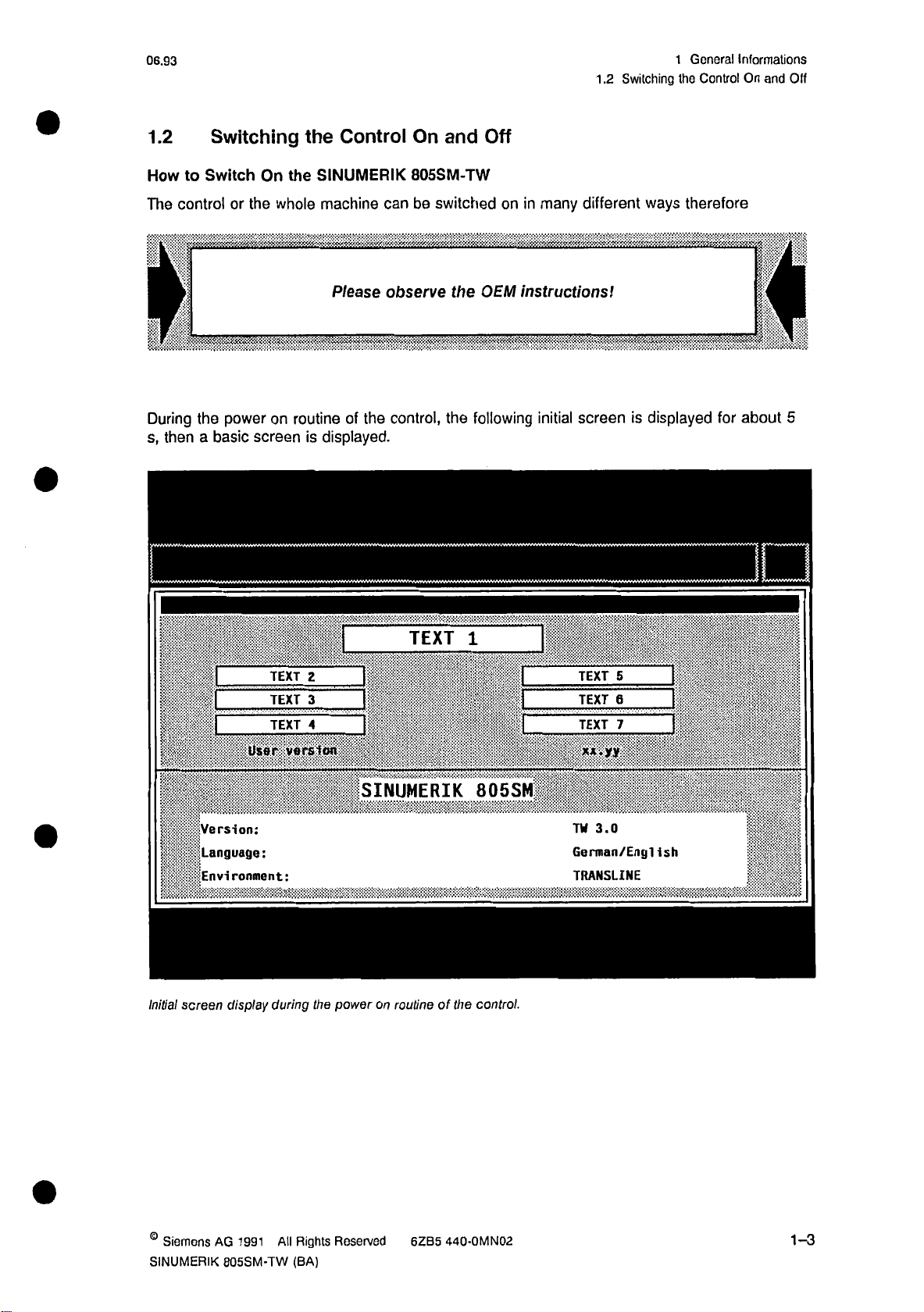
The
During
s,
Switching
Switch
to
controlorthe
power
the
a
then
basic
*
the
On
whole
on
routine
screen
the
Control
SINUMERIK
machine
Please
the
of
displayed.
is
On
805SM-TW
be
can
observe
control,
Off
and
switched
OEM
the
following
the
on
many
in
instructions!
i/..*.
A.
initial
different
<\
screen
ways
displayed
is
therefore
a
if
for
4
about
A
V
5
s
;
IN
>1
8
Initial
Version:
Language:
Environment:
display
screen
User:
TEXT
TEXT
TEXT
version
during
2
3
4
SINUMERIK
power
the
TEXT
on
routineofthe
1
805SM
control.
5
TEXT
TEXT
TEXT
x**yy
iii;-
TW
3.0
Gcrman/Engl
TRANSLINE
6
7
T?
ish
©
Siemens
SINUMERIK
AG
1991
805SM-TW
All
Rights
(BA)
Reserved
6ZB5
440-0MN02
1-3
Page 15
1
General
.2
1
Informations
Switching
the
Control
On
and
06.93
Off
Explanation
the
lower
In
•
Example:
3.0
TW
German/English
TRANSLINE
upper
the
In
as
the
edition
You
also
environment.
Notes:
during
If
•
•
with
After
the
successful
displayed
PLC
program
switch
to
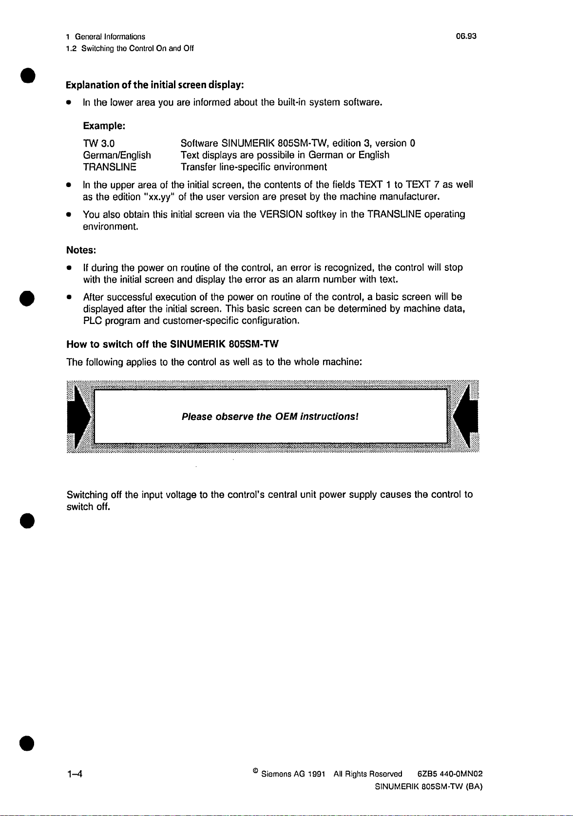
How
following
The
the
of
area
obtain
power
the
initial
after
off
applies
screen
initial
you
are
Software
Text
Transfer
the
area
"xx.yy"
this
screen
initial
of
the
of
initial
on
routineofthe
and
executionofthe
the
initial
customer-specific
and
SINUMERIK
the
to
control
the
display:
informed
displays
line-specific
screen,
user
screen
display
screen.
as
about
the
SINUMERIK
are
possibile
environment
the
contents
version
via
the
power
This
805SM-TW
well
are
VERSION
the
control,
errorasan
routine
on
screen
basic
configuration.
as
to
built-in
805SM-TW,
preset
system
in
German
of
the
by
the
softkey
an
error
is
alarm
number
of
the
can
be
whole
the
machine:
software.
edition3,version
or
English
TEXT
fields
machine
in
recognized,
control,
manufacturer.
TRANSLINE
the
the
text.
with
a
basic
determined
1
to
control
by
screen
0
7
TEXT
operating
will
will
machine
well
as
stop
be
data,
Switching
switch
off.
off
the
input
Please
voltage
to
the
observe
control’s
the
central
OEM
instructions
power
unit
!
supply
causes
the
control
to
1-4
©
Siemens
AG
1991
All
Rights
Reserved
SINUMERIK
6ZB5
440-0MN02
805SM-TW
(BA)
Page 16
06.93
2
Control
Elements
2.1
Operating
and
Keyboard
Areas
Elements
2
2.1
Control
Keyboard
%
A
H
G
M
V
u
m
B
.f
w
L_i
Elements
Elements
and
Operating
Areas
a
c
8
7
4
1
+/-
#
m
Y
=&
F
L
T
\
z
LF
E
D
I
J
K
RS
P°
/
X
)
(
@
9
*
5
6
3
2
0
X
:fS
+:
gHB
m
0
mm
-o
m
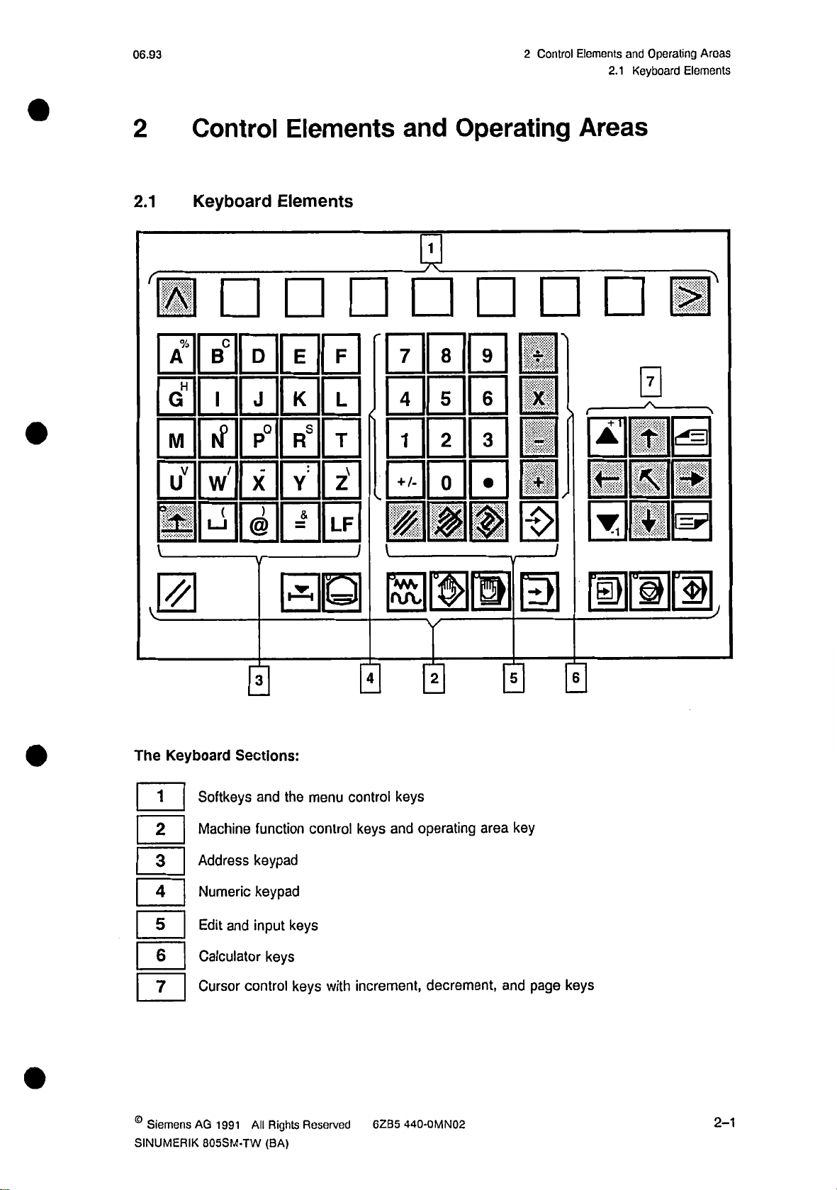
Keyboard
The
1
|
|
|
|
|
|
|
|
2
|
3
|
4
|
5
|
6
|
7
|
0
Sections:
Softkeys
Machine
Address
Numeric
Edit
Calculator
Cursor
and
and
function
keypad
keypad
input
control
fÿ1H
menu
the
control
keys
keys
keys
control
with
0
keys
keys
and
increment,
0
operating
decrement,
area
0
key
and
page
0
keys
®
Siemens
SINUMERIK
AG
1991
805SM-TW
All
Rights
(BA)
Reserved
6ZB5
440-0MN02
2-1
Page 17
2
Control
2.1.1
Elements
Explanation
and
of
Operating
Keyboard
the
Areas
Elements
06.93
2.1.1
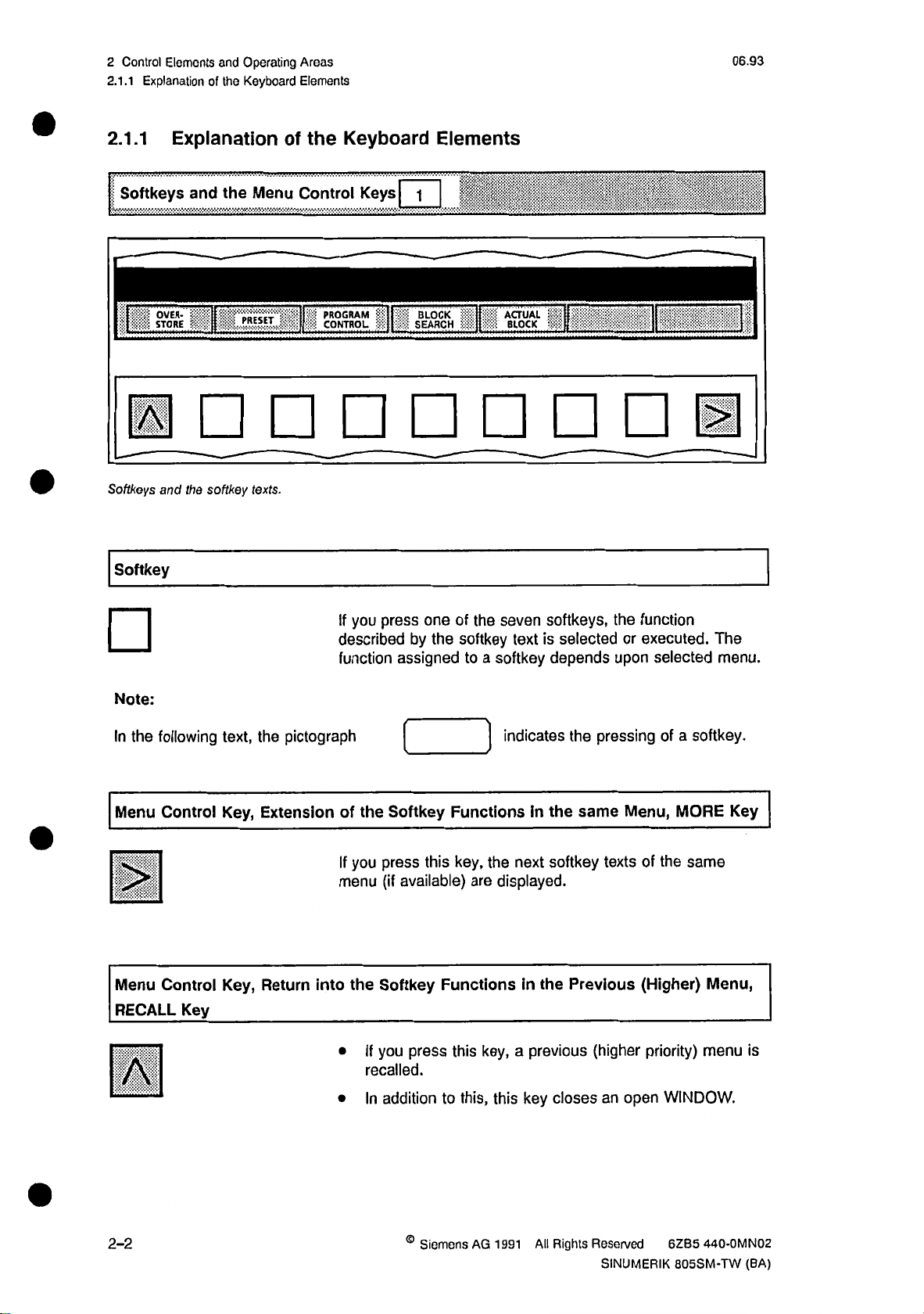
Softkeys
.
Softkeys
Softkey
Explanation
the
and
OVER-
STOKE
and
the
n
[|
softkey
Menu
PRESET
texts.
the
of
Control
II
||
Keyboard
Keys|
PROGRAM
CONTROL
Elements
|
1
BLOCK
SEARCH
ACTU
BLO
fU
sL_i
Note:
In
the
Menu
0
Menu
RECALL
0
following
Control
Control
Key
text,
Key,
Key,
_
pictograph
the
Extension
Return
into
you
press
If
described
the
you
the
Softkey
press
(if
Softkey
you
If
assigned
function
of
If
menu
•
recalled.
addition
In
•
of
one
by
available)
press
softkey
the
to
FunctionsInthe
key,
this
Functionsinthe
this
this,
to
seven
the
a
softkey
indicates
the
displayed.
are
key,
this
softkeys,
is
selectedorexecuted.
text
depends
pressing
the
same
softkey
next
previous
a
key
closes
texts
Previous
(higher
an
the
upon
Menu,
open
function
selected
a
of
MORE
the
of
(Higher)
priority)
WINDOW.
The
menu.
softkey.
same
Menu,
menu
Key
is
2-2
©
Siemens
AG
1991
All
Rights
Reserved
SINUMERIK
440-0MN02
6ZB5
805SM-TW
(BA)
Page 18
06.92
2
2.1.1
Elements
Control
Explanation
of
and
Keyboard
the
Operating
Elements
Areas
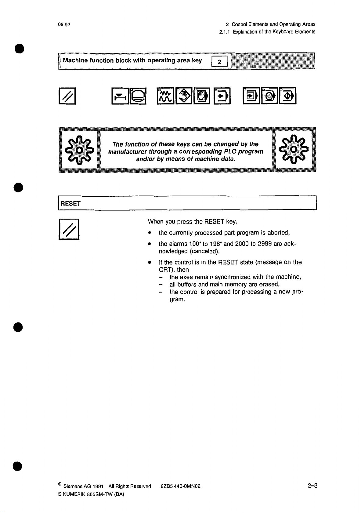
Machine
El
Is!
RESET
function
with
block
EH
The
function
manufacturer
and/or
operating
H
these
of
through
by
means
you
When
the
•
the
•
nowledged
key
area
keys
can
a
corresponding
machine
of
the
press
currently
alarms
processed
100*
(canceled).
2
changed
be
RESET
to
196*
program
PLC
data.
key,
program
part
2000to2999
and
mil
by
the
is
||
n
aborted,
ack¬
are
•
the
If
CRT),
the
-
all
-
the
-
gram.
control
then
axes
buffers
control
the
in
is
remain
main
and
prepared
is
RESET
synchronized
state
memory
processing
for
are
(message
the
with
erased,
on
machine,
a
new
pro¬
the
©
Siemens
SINUMERIK
AG
All
1991
805SM-TW
Rights
(BA)
Reserved
6ZB5
440-0MN02
2-3
Page 19
2
Control
2.1.1
Elements
Explanation
of
and
the
Operating
Keyboard
Areas
Elements
09.91
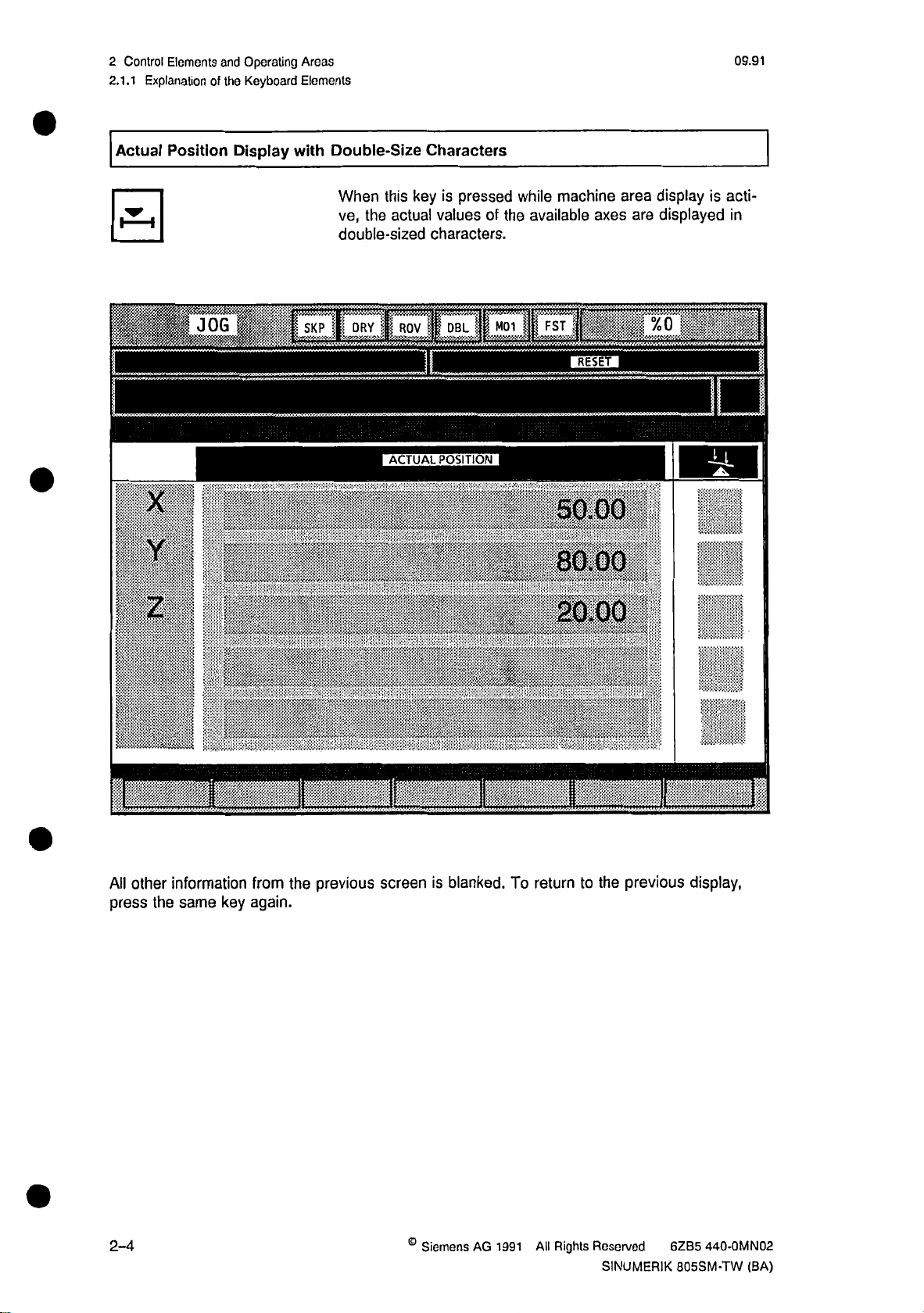
Actual
4
x
v
P::
1
Z
ifiigiiflif!!
i|i||lil
I
I
:P%,
'
i
Position
JOG
mi
mmi
;
4
'*
Display
$
§rr
fc:
PI
s-
Double-Size
with
When
ve,
the
double-sized
|
.....
........
tlliifill
1
111
mm
|
.............
Characters
area
is
key
this
actual
...........
ACTUAL
pressed
values
characters.
;
....
POSITION
of
the
:
yS®
*•
P
siy
%
y
-X
•
>
>
mm*
machine
while
available
...
:
50.00
80.00;:;
v.wA
&
&
”
axes
RESET
.vtwttv.
display
are
,
m
I
;
'ÿ>>>
iiMisi
&
is
displayed
-U
111
MM
'
f
acti¬
in
'
h
I
i
I
.
All
other
press
the
2-4
.
information
key
same
-1
from
again.
the
previous
II
screen
©
is
blanked.
Siemens
AG
1991
To
return
All
Rights
previous
the
to
Reserved
SINUMERIK
6ZB5
805SM-TW
J
display,
440-0MN02
!
(BA)
Page 20
09.91
2
2.1.1
Elements
Control
Explanation
of
and
Keyboard
the
Operating
Elements
Areas
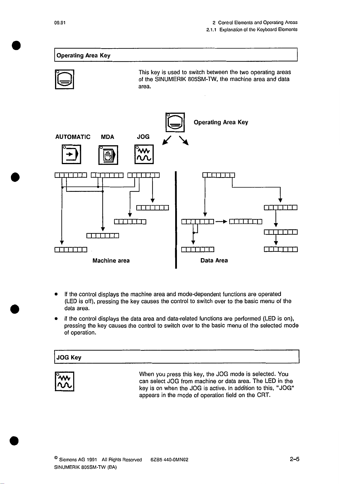
Operating
H
AUTOMATIC
m
i i i i i
n
i
Area
i
Key
MDA
H
i
i iii
n
i i i i
I I III
3
This
of
area.
JOG
i i i
I
~T~1
key
is
SINUMERIK
the
0
1
1
i
i
m
i i
used
to
switch
805SM-TW,
Operating
I III I
j
between
the
I I I I I I
ill
the
machine
Area
T~1
i i i i
two
Key
operating
area
I I I I
m
i
and
areas
data
I
iTl
i i i i
i
If
(LED
data
If
pressing
of
JOG
n]
n
i
the
control
off),
is
area.
the
control
the
operation.
Key
Machine
displays
pressing
displays
causes
key
area
the
the
the
machine
key
causes
area
data
the
control
When
can
key
appears
area
the
and
to
you
select
on
is
it
and
mode-dependent
control
data-related
press
JOG
the
mode
over
this
from
the
switch
when
in
m
i i
i
Data
switch
to
functions
the
to
key,
machine
is
JOG
of
operation
Area
over
basic
JOG
the
active.
functions
to
are
menu
modeisselected.
or
data
In
field
are
basic
the
performed
of
area.
addition
the
on
operated
menu
selected
the
The
to
CRT.
i
i i i
(LED
LED
this,
i
m
of
the
on),
is
mode
You
the
in
"JOG"
©
Siemens
SINUMERIK
AG
1991
805SM-TW
All
Rights
(BA)
Reserved
6ZB5
440-0MN02
2-5
Page 21
2
Control
2.1.1
Elements
Explanation
and
of
Operating
Keyboard
the
Areas
Elements
06.93
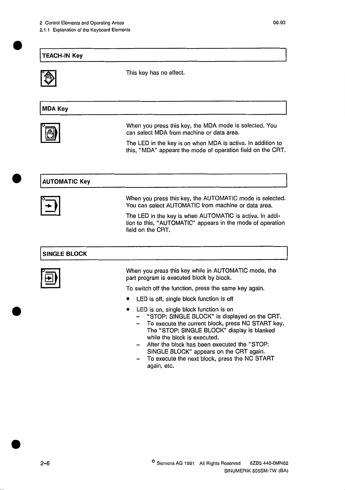
TEACH-IN
Key
MDA
H
AUTOMATIC
m
Key
Key
This
When
can
The
this,
When
You
The
tion
to
field
key
has
you
select
LED
"MDA"
you
can
select
LED
this,
on
the
no
effect.
key,
this
press
machine
from
MDA
in
the
appears
press
in
the
"AUTOMATIC"
CRT.
is
key
the
key,
this
AUTOMATIC
key
is
the
on
when
mode
the
from
AUTOMATIC
when
appears
modeisselected.
MDA
area.
data
or
MDA
of
AUTOMATIC
active.Inaddition
is
operation
machine
is
the
mode
in
You
to
the
field
on
modeisselected.
or
data
active.
of
CRT.
area.
addi¬
In
operation
SINGLE
II
BLOCK
When
part
To
switch
LED
•
LED
•
-
-
-
-
you
press
program
off
off,
is
on,
is
"STOP:
To
execute
The
while
After
SINGLE
To
execute
again,
this
key
is
executed
function,
the
single
block
single
block
SINGLE
the
current
"STOP:
the
the
SINGLE
blockisexecuted.
block
has
BLOCK"
the
next
etc.
while
in
by
block
press
function
function
BLOCK"
block,
BLOCK"
been
appears
block,
AUTOMATIC
block.
key
same
the
is
off
on
is
displayed
is
press
NC
display
executed
on
press
the
the
CRT
the
mode,
again.
on
the
START
is
blanked
"STOP:
again.
NC
START
the
CRT.
key.
2-6
Siemens
AG
1991
All
Rights
Reserved
SINUMERIK
440-0MN02
6ZB5
805SM-TW
(BA)
Page 22
06.93
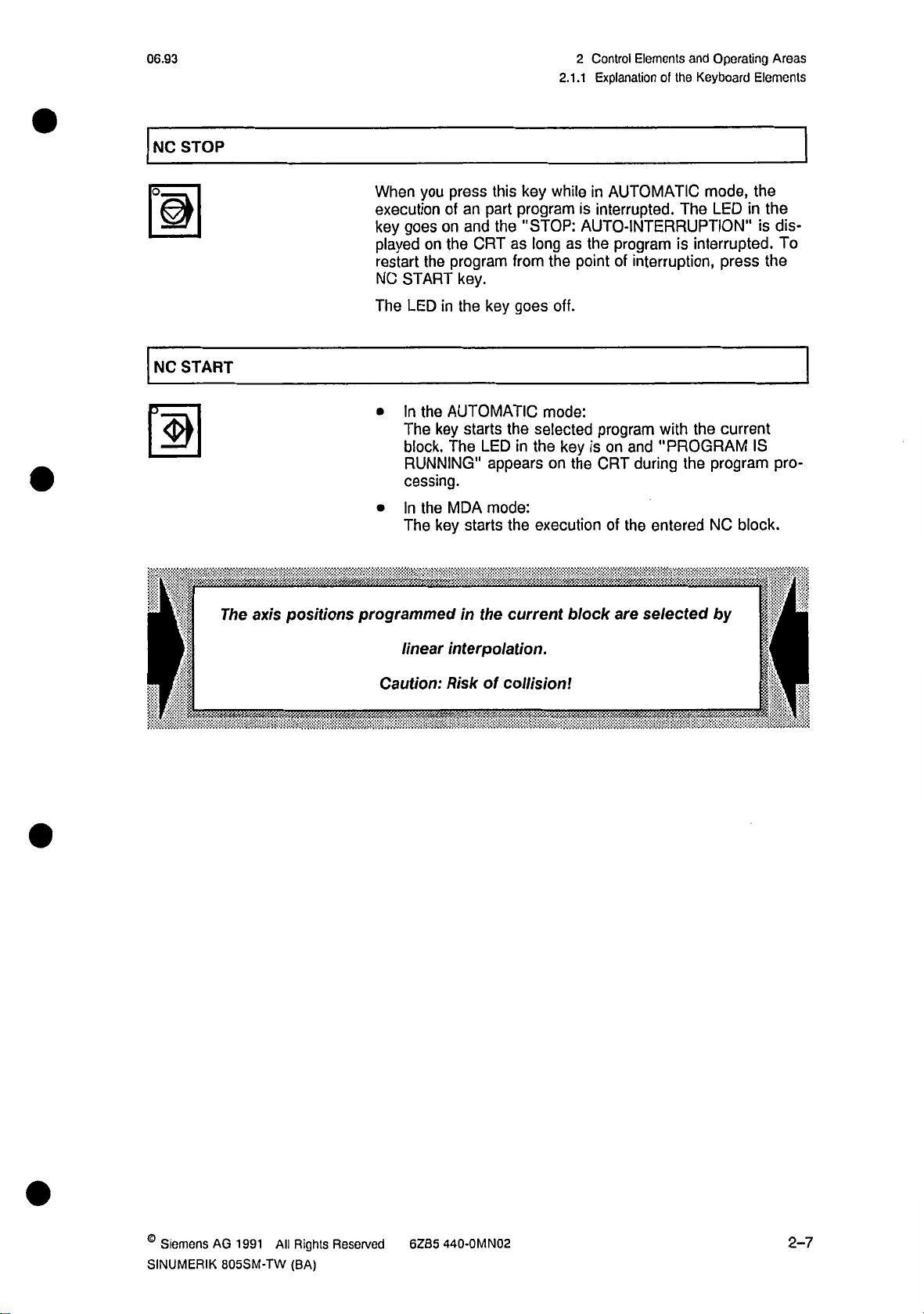
NC
STOP
2
2.1.1
Control
Elements
Explanation
ol
and
Keyboard
the
Operating
Elements
Areas
II
NC
3
START
The
l
axis
positions
you
When
execution
goes
key
played
restart
NC
The
•
on
the
START
LED
In
the
key
The
block.
RUNNING"
cessing.
the
In
•
programmed
The
key
key
this
press
part
the
CRT
key
program
"STOP:
as
from
goes
an
of
on
and
the
program
key.
in
the
AUTOMATIC
the
starts
The
LED
in
appears
MDA
mode:
the
starts
in
the
current
while
in
is
AUTO-INTERRUPTION"
long
as
the
point
the
off.
mode:
selected
key
on
isonand
the
the
execution
block
AUTOMATIC
interrupted.
program
interruption,
of
program
with
"PROGRAM
during
CRT
entered
the
of
are
selected
mode,
The
LED
interrupted.
is
press
the
current
program
the
NC
by
the
the
in
is
the
IS
block.
!
dis¬
To
pro¬
Hi
f
interpolation.
linear
.
f
a
:
Caution:
•
Risk
of
collision!
'
v:
.
i
©
Siemens
SINUMERIK
AG
1991
805SM-TW
All
Rights
(BA)
Reserved
6ZB5
440-0MN02
2-7
Page 23
Control
2
2.1.1
Elements
Explanation
and
ol
Operating
Keyboard
the
Areas
Elements
06.92
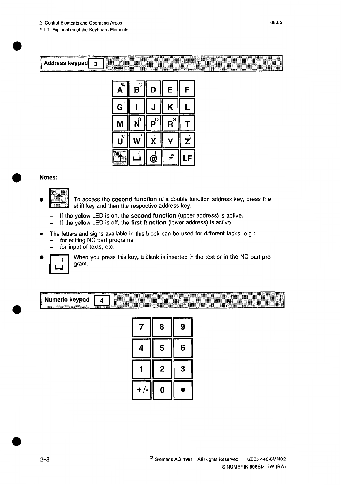
Address
Notes:
•
H
-
-
If
the
If
the
keypad
To
access
shift
yellow
yellow
key
3
and
LED
LED
the
is
is
A
G
M
u
3
J-
second
then
on,
off,
%
B
H
I
tf
V
w
1
—
function
the
respective
second
the
first
the
c
/
(
1
function
D
J
P°
X
)
@
of
address
function
E
K
RS
:
Y
=&
a
double
(lower
F
L
T
s
Z
LF
function
key.
(upper
address)
address
address)
is
is
active.
active.
key,
press
the
The
letters
editing
for
-
-
for
input
•0
Numeric
keypad
and
of
When
gram.
signs
NC
texts,
you
available
programs
part
etc.
press
4
|
this
in
key,
this
a
7
4
1
+
block
blank
/-
can
inserted
is
8
5
2
0
be
used
9
6
3
in
different
for
the
text
or
tasks,
in
the
e.g.:
NC
part
pro¬
2-8
©
Siemens
AG
1991
All
Rights
Reserved
SINUMERIK
440-0MN02
6ZB5
805SM-TW
(BA)
Page 24
06.93
2
2.1.1
Control
Elements
Explanation
of
and
Keyboard
the
Operating
Elements
Areas
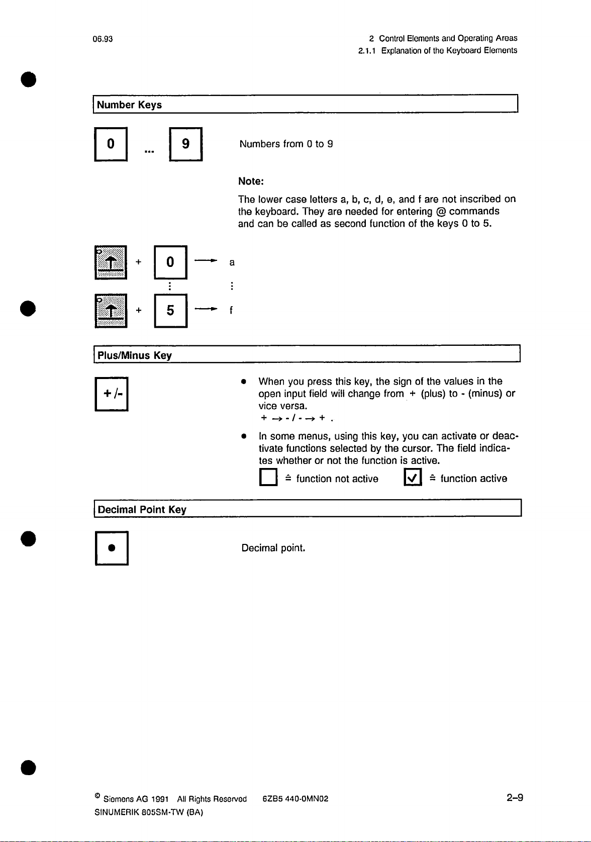
Number
Keys
-
0+0
0*
Plus/Minus
0
Key
0
0
:
Numbers
Note:
The
keyboard.
the
and
a
:
f
•
lower
can
When
open
vice
-»-/-->
+
0
to
letters
They
press
field
9
are
will
.
+
from
case
be
calledassecond
you
input
versa.
a,
b,
needed
this
change
c,d,e,
function
key,
for
the
from
and
f
entering
of
the
of
sign
(plus)
+
are
not
@
commands
keys
valuesinthe
the
to
inscribed
5.
0
to
(minus)
-
on
or
Decimal
Point
Key
In
•
tivate
tes
|~l
Decimal
some
functions
whether
-
point.
menus,
or
function
using
selectedbythe
the
not
not
this
function
active
key,
you
can
cursor.
is
active.
0
activate
The
function
=
field
deac¬
or
indica¬
active
©
Siemens
SINUMERIK
AG
1991
All
805SM-TW
Rights
(BA)
Reserved
6ZB5
440-0MN02
2-9
Page 25
2
Control
2.1.1
Elements
Explanation
and
of
Operating
Keyboard
the
Areas
Elements
06.92
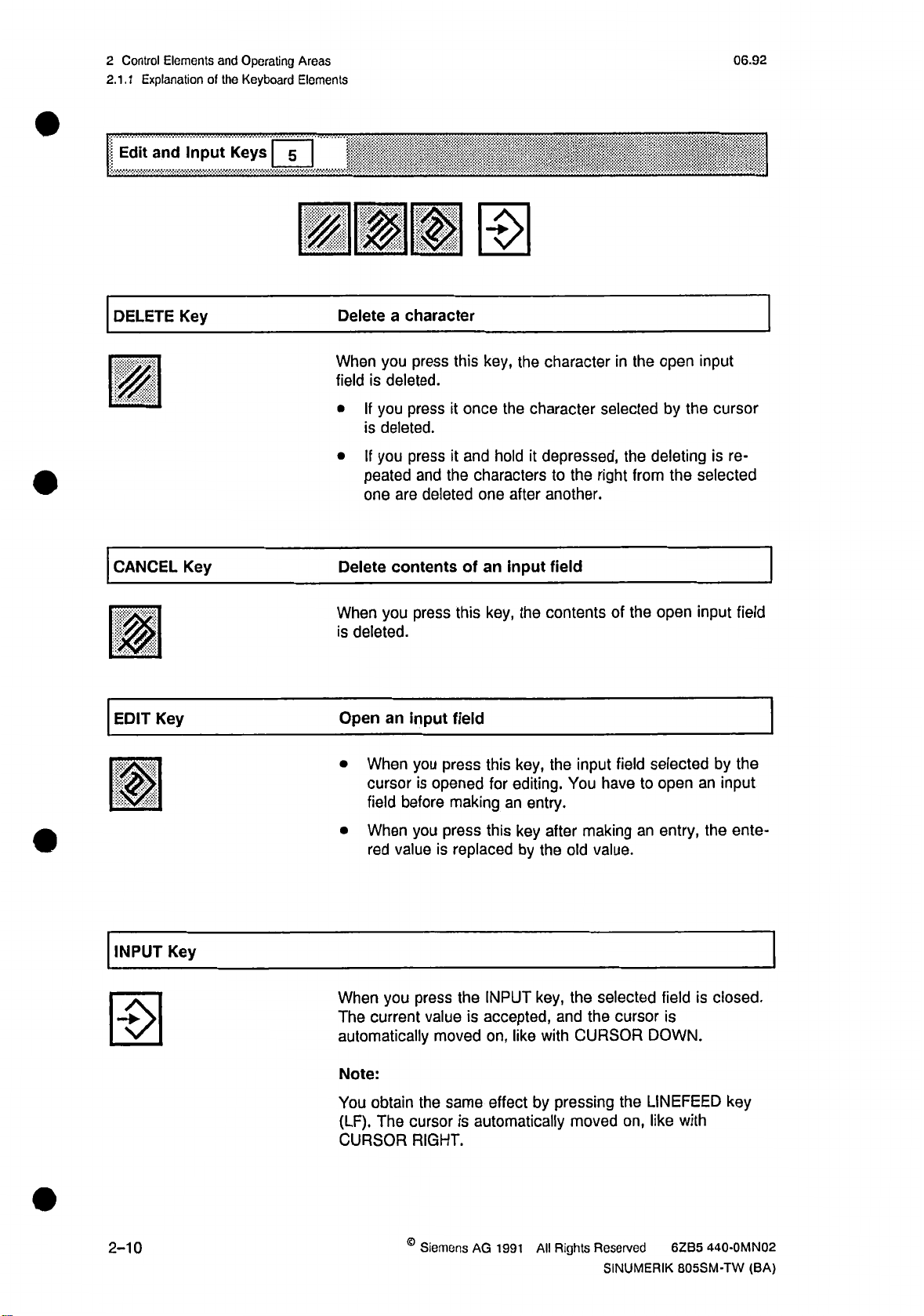
Edit
DELETE
0
CANCEL
and
Input
Key
Key
Keys
5
HMSm
a
you
is
deleted.
you
If
is
deleted.
you
If
peated
one
are
contents
character
this
press
press
press
it
it
the
and
deleted
once
and
of
key,
characterstothe
one
an
Delete
When
field
•
•
Delete
the
the
hold
after
input
character
character
depressed,
it
another.
field
the
in
selected
the
right
from
open
by
the
deleting
the
||f|:
ill's
input
cursor
is
re¬
selected
m
Key
EDIT
HI
INPUT
|
El
Key
you
an
before
value
you
current
press
input
you
is
you
press
When
deleted.
is
Open
When
•
cursor
field
When
•
red
When
The
automatically
this
field
press
opened
making
press
replaced
is
the
value
moved
key,
this
for
an
this
INPUT
accepted,
is
on,
the
contents
key,
the
editing.
entry.
key
after
by
the
key,
like
with
input
You
making
old
value.
the
selected
and
the
CURSOR
of
field
have
cursor
open
the
selected
open
to
an
DOWN.
entry,
field
is
input
by
an
the
is
closed.
field
the
input
ente¬
2-10
Note:
obtain
You
The
(LF).
CURSOR
the
same
cursor
RIGHT.
©
Siemens
effect
automatically
is
AG
1991
by
pressing
Rights
All
moved
Reserved
SINUMERIK
the
LINEFEED
like
on,
with
440-0MN02
6ZB5
805SM-TW
key
(BA)
Page 26
06.92
2
2.1.1
Control
Elements
Explanation
of
and
Keyboard
the
Operating
Elements
Areas
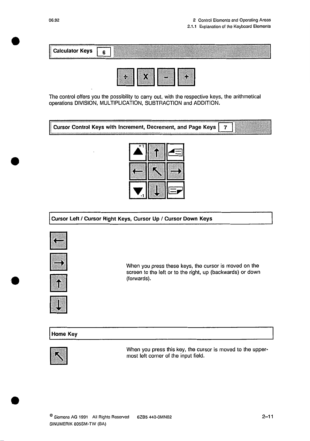
Calculator
control
The
operations
Cursor
Control
Keys
|
you
offers
DIVISION,
Keys
0
IEEE
possibility
the
MULTIPLICATION,
with
Increment,
to
carry
+
out,
SUBTRACTION
Decrement,
1
T
with
cÿ=l
the
III
i
(=?
wm
respective
and
Page
and
keys,
ADDITION.
Keys
arithmetical
the
7
l
I
Cursor
Left/Cursor
E
E
E
m
Home
E
Key
Right
Keys,
When
screen
(forwards).
When
most
Cursor
you
to
you
left
Up
press
left
the
press
corner
Cursor
/
these
or
this
of
to
the
keys,
the
key,
input
Down
right,
the
Keys
the
cursor
field.
cursor
(backwards)
up
is
moved
is
moved
to
on
or
the
the
down
upper¬
©
Siemens
SINUMERIK
AG
1991
805SM-TW
All
Rights
(BA)
Reserved
6ZB5
440-0MN02
2-11
Page 27
2
Control
2.1.1
Elements
Explanation
and
of
Operating
Keyboard
the
Areas
Elements
06.92
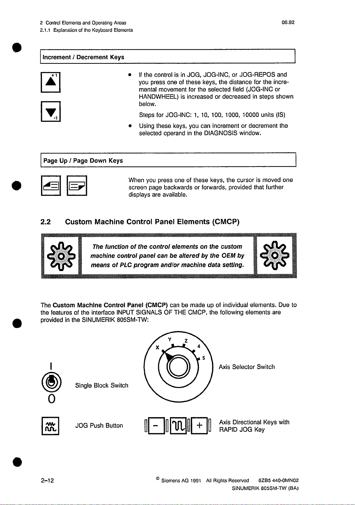
Increment/Decrement
0
0
Down
Page
Page
S@
2.2
/
Up
Custom
Machine
Keys
Keys
If
the
•
you
press
mental
HANDWHEEL)
below.
Steps
Using
•
selected
you
When
screen
displays
page
Control
control
one
movement
JOG-INC:
for
these
operand
press
backwards
available.
are
Panel
JOG,
in
is
these
of
for
is
increased
1,
keys,
you
in
the
of
these
one
Elements
JOG-INC,
keys,
selected
the
or
100,
10,
increment
can
DIAGNOSIS
keys,
forwards,
or
(CMCP)
JOG-REPOS
or
distance
the
field
decreased
1000,
or
window.
cursor
the
provided
for
(JOG-INC
in
steps
10000
units
decrement
is
that
incre¬
the
or
shown
(IS)
moved
further
and
the
one
$
Custom
The
the
features
provided
I
0
in
Machine
of
the
Single
The
function
machine
means
the
interface
SINUMERIK
Block
of
Control
Switch
of
the
control
PLC
INPUT
805SM-TW:
panel
program
Panel
SIGNALS
(CMCP)
control
can
and/or
X
elementsonthe
be
alteredbythe
machine
be
THE
made
CMCP,
Z
can
OF
Y
D
custom
by
OEM
setting.
data
m
of
up
individual
following
the
4
5
Selector
Axis
elements.
elements
Switch
are
Due
to
2-12
JOG
Push
Button
OB0I
©
Siemens
AG
1991
All
Axis
RAPID
Rights
Directional
JOG
Reserved
SINUMERIK
Keys
Key
6ZB5
805SM-TW
with
440-0MN02
(BA)
Page 28
06.92
m
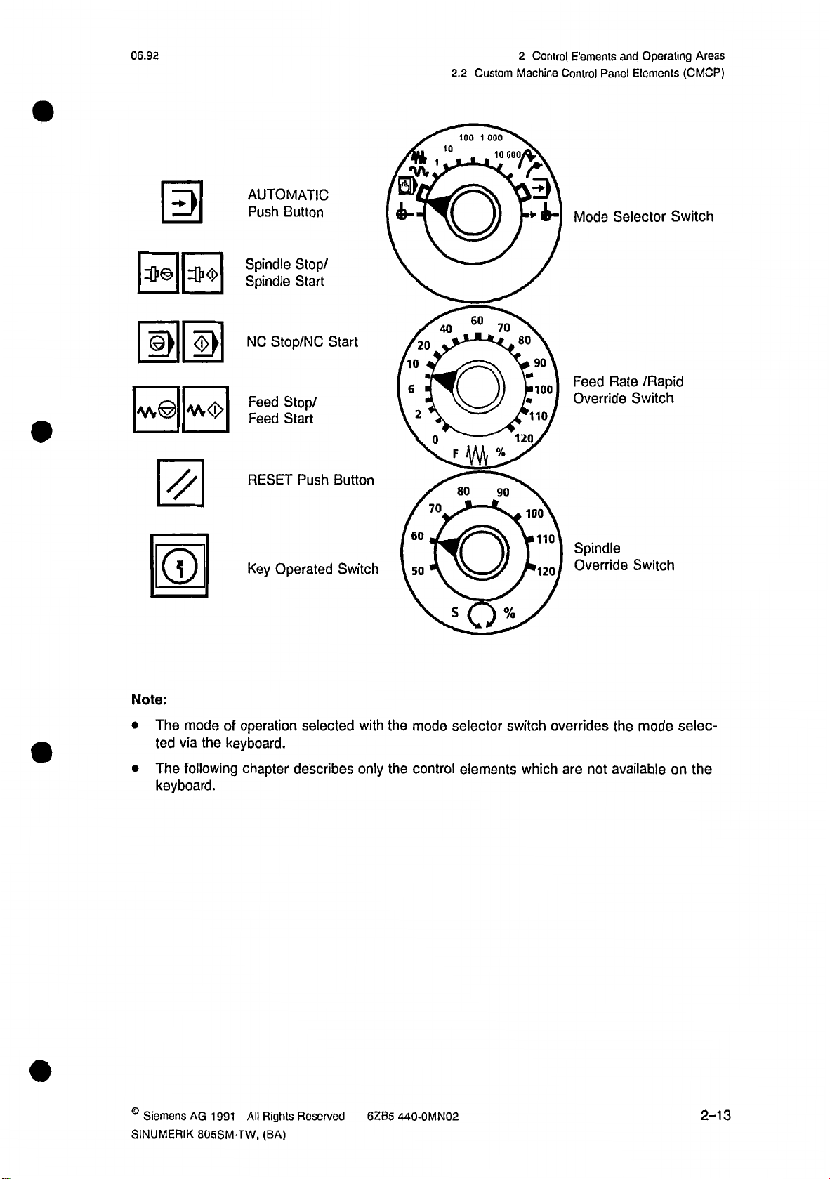
AUTOMATIC
Push
Button
•w
0>
4-
2.2
too
10
1
O
Custom
i
ooo
10
000
2
Control
Machine
r
3
Elements
Control
Mode
and
Panel
Selector
Operating
Elements
Switch
Areas
(CMCP)
Mm
©
W<l>
AAr
0
©
Spindle
Spindle
NC
Stop/NC
Stop/
Feed
Feed
Start
RESET
Key
Operated
Stop/
Start
Push
Start
Button
Switch
10
6
60
50
2
20
40
0
70
60
Fÿ%
80
O
s
70
90
%
80
fm
120
90
100
’110,
100
110
r120
Rate
Feed
Override
Spindle
Override
/Rapid
Switch
Switch
Note:
The
•
ted
The
•
keyboard.
mode
via
the
following
of
operation
keyboard.
chapter
selected
describes
with
only
the
the
mode
control
selector
elements
switch
which
overrides
are
not
the
mode
available
selec¬
on
the
©
Siemens
SINUMERIK
AG
1991
805SM-TW,
All
Rights
(BA)
Reserved
6ZB5
440-0MN02
2-13
Page 29
Control
2
2.2.1
Elements
Explanation
and
of
Operating
the
Custom
Areas
Machine
Control
Panel
06.92
Components
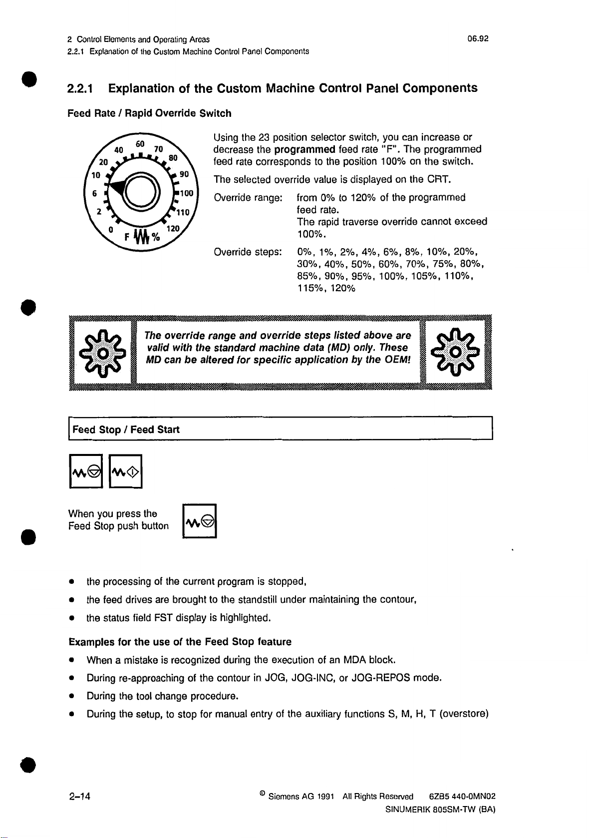
2.2.1
Feed
Explanation
Rate
20
10
6
2
g
/
Rapid
40
6„°
The
valid
MD
of
Override
70
80
90
100
'110
120
override
with
can
be
the
Switch
Using
decrease
feed
The
Override
Override
range
standard
the
altered
Custom
the
rate
selected
and
for
Machine
position
23
programmed
the
corresponds
override
range:
steps:
override
machine
specific
from
feed
The
100%.
0%,
30%,
85%,
115%,
application
Control
selector
to
value
0%
rate.
rapid
1%,
40%,
90%,
steps
data
feed
the
is
to
2%,
120%
listed
(MD)
Panel
switch,
rate
position
displayed
20%
1
traverse
4%,
50%,
95%,
above
only.
by
the
Components
can
you
The
"F".
00%
on
1
on
the
programmed
the
of
override
6%,
8%,
60%,
70%,
100%,
These
105%,
are
OEMl
increase
programmed
the
CRT.
cannot
10%,
75%,
or
switch.
exceed
20%,
80%,
110%,
n
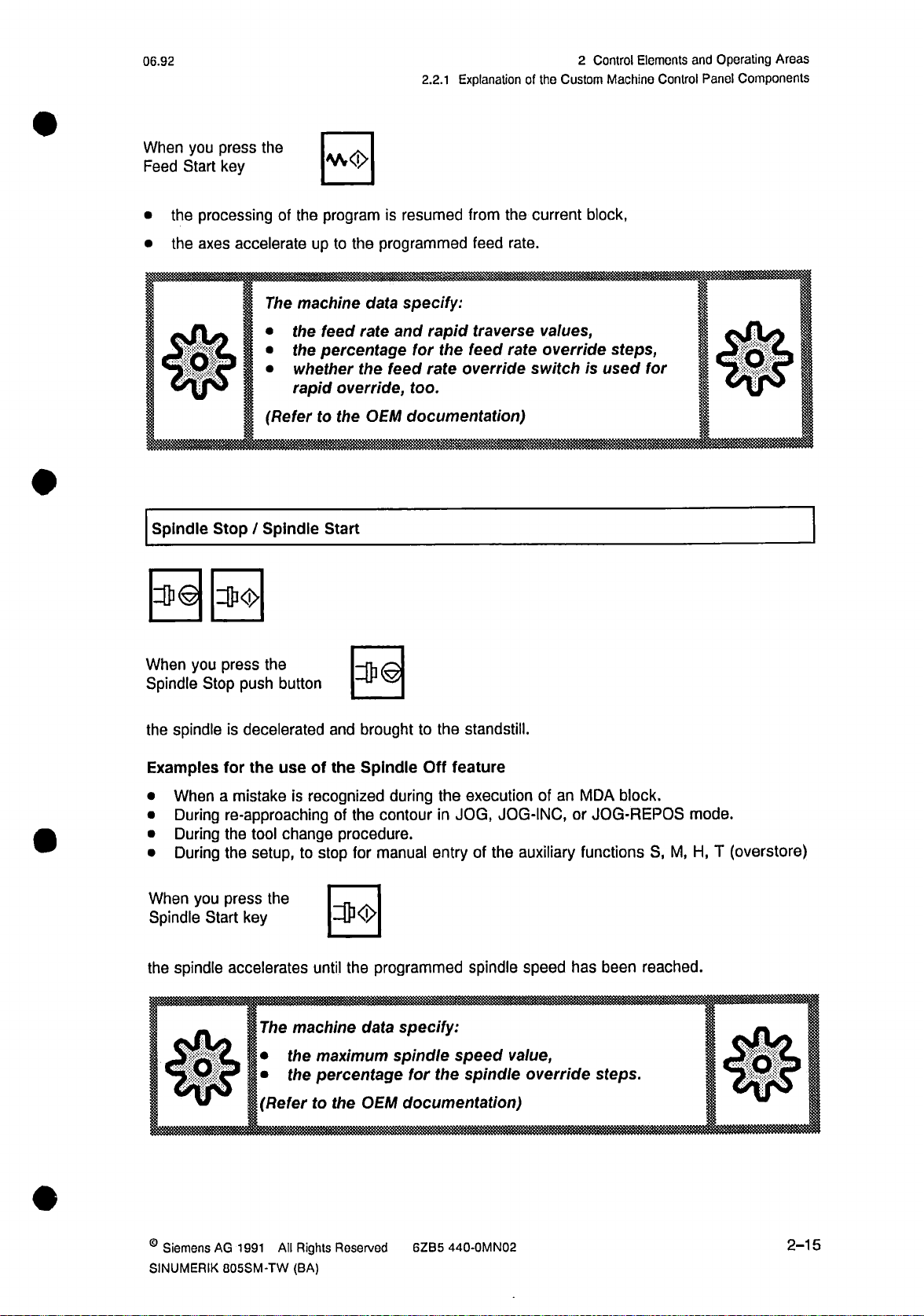
Feed
Stop
|v»©j
you
When
Stop
Feed
the
•
the
•
the
•
Examples
When
•
During
•
During
•
During
•
Feed
/
H
press
push
processing
drives
feed
status
for
a
mistake
re-approaching
the
the
the
button
field
the
tool
setup,
Start
|*A©|
the
of
current
brought
are
display
FST
use
change
the
of
recognized
is
of
procedure.
to
stop
program
to
the
highlighted.
is
Feed
during
the
contour
manual
for
is
standstill
feature
Stop
the
in
entry
stopped,
under
execution
JOG-INC,
JOG,
the
of
maintaining
an
of
MDA
or
auxiliary
functions
contour,
the
block.
JOG-REPOS
M,
S,
mode.
H,
T
(overstore)
2-14
©
Siemens
AG
1991
All
Rights
Reserved
SINUMERIK
440-0MN02
6ZB5
805SM-TW
(BA)
Page 30
06.92
When
Feed
you
Start
press
key
the
2.2.1
|ÿ<j>|
Explanation
of
the
2
Control
Custom
Elements
Machine
Control
and
Panel
Operating
Components
Areas
the
•
the
•
y
Spindle
When
Spindle
processing
accelerate
axes
c.
?
P
Stop/Spindle
you
press
Stop
push
of
The
the
•
the
•
whether
•
rapid
(Refer
the
button
program
the
to
up
machine
feed
percentage
override,
to
the
Start
|ii|
resumed
is
programmed
the
specify:
data
and
rate
the
feed
documentation)
OEM
for
too.
rapid
the
rate
the
from
rate.
feed
traverse
feed
rate
override
current
values,
override
switch
block,
steps,
is
used
for
spindle
the
Examples
When
•
During
•
During
•
During
•
you
When
Spindle
the
Start
spindle
—
SV
decelerated
is
the
for
a
re-approaching
the
the
press
accelerates
P
use
mistake
key
is
change
tool
setup,tostop
the
machine
The
the
•
the
•
(Refer
brought
and
the
of
recognized
Spindle
of
the
procedure.
manual
for
programmed
the
until
data
maximum
percentage
OEM
the
to
the
to
Off
feature
during
contour
the
JOG,
in
entry
specify:
for
speed
the
spindle
documentation
standstill.
execution
JOG-INC,
the
auxiliary
of
spindle
spindle
speed
value,
override
)
of
an
MDA
or
JOG-REPOS
functions
has
been
steps.
block.
S,
reached.
M,
mode.
H,
T
(overstore)
©
Siemens
SINUMERIK
AG
All
1991
805SM-TW
Rights
(BA)
Reserved
6ZB5
440-0MN02
2-15
Page 31

2
Control
2.2.1
NC
Elemonts
Explanation
Stop
/
NC
and
of
Start
Operating
Custom
the
mm
you
When
Stop
NC
the
•
the
•
When
NC
Start
of
operation
being
push
processing
"STOP:
you
key
selected,
the
press
button
of
the
AUTO-INTERRUPTION"
press
the
the
with
AUTOMATIC
mode
Areas
Machine
si
current
SI
Control
part
Components
Panel
program
message
is
stopped,
is
displayed
on
the
06.92
CRT.
the
•
•
The
Directional
selected
the
"PROGRAM
NC
+
The
directional
JOG
In
•
tive
JOG-INC
In
•
the
RAPID
respective
and
Start
Keys
plus
mode,
direction,
sub-mode,
JOG
Key
program
part
IS
NC
Stop
and
when
direction
is
started
RUNNING"
commands
keys
minus
press
you
you
when
a
distance
resumed
or
message
can
have
the
hold
and
press
equal
displayed
is
be
also
following
the
and
the
to
from
given
key,
the
release
selected
the
current
on
the
via
the
functions:
selected
a
key,
the
distance
block,
CRT.
respective
axis
traverses
selected
increment.
keyboard
the
in
axis
traverses
keys.
respec¬
in
0
When
you
Together
2-16
press
with
one
the
of
RAPID
directional
the
JOG
Key
keys,
0or0
©
Siemens
AG
1991
All
Rights
Reserved
SINUMERIK
440-0MN02
6ZB5
805SM-TW
(BA)
Page 32

06.92
2.2.1
Explanation
of
tho
Control
2
Custom
Eloments
Machine
Control
and
Panel
Operating
Components
Areas
The
selected
PQC
Key
Operated
Using
m
1
this
axis
switch
traverses
The
machine
the
•
the
•
the
•
Switch
you
can
the
with
data
feed
rate
rapid
traverse
incremental
the
lock
entry
Theisthe
moved.
Thisisthe
be
sible
rapid
traverse
specify:
value,
speed
speed
data,
of
All
removed.
(unlocked).
speed
value,
value.
disable
locked
functions
unlocked
position
functions
All
the
in
some
the
of
protected
position
of
protected
respective
functions,
switch.
by
the
switch.
the
by
direction.
etc.
The
switch
the
the
switch
key
The
0
can
locked.
are
key
cannot
are
re¬
be
acces¬
*
RESET
0
The
setting.
key
To
lock
see
function
is
if
it
OEM
When
the
•
the
•
nowledged
If
•
CRT)
-
-
-
depends
you
in
used
documentation.
you
press
the
currently
alarms
the
control
then:
the
all
the
gram.
processed
100*to196*
(canceled).
isinthe
remain
axes
buffers
control
upon
control,
RESET
main
and
prepared
is
refer
2000
state
processing
for
data
to
machine
key,
program
and
RESET
synchronized
memory
the
aborted,
is
2999
to
(message
with
erased,
are
are
machine,
the
of
ack¬
on
a
new
the
pro¬
©
Siemons
SINUMERIK
1
AG
991
805SM-TW
All
Rights
(BA)
Reserved
6ZB5
440-OMN02
2-17
Page 33

Control
Explanation
of
Elements
2
2.2.1
Mode
4-
the
With
PRESET
•
MDA
•
JOG
•
JOG
•
JOG
•
AUTOMATIC
•
JOG
•
and
of
Operation
100
10
1
o
mode
of
INC
REPOS
REF
Operating
the
Custom
Selector
1
000
00
10
operation
r
3
Areas
Machine
Switch
selector
Control
switch,
Panel
Components
you
can
set
the
following
06.93
modes:
Note:
a
If
mode
selected
Single
I
0
selector
keyboard.
via
Block
switch
Switch
Using
AUTOMATIC
Switch
Switch
If
the
to
•
"NO
after
•
sage
to
•
available,
is
switch,
this
in
position
in
position
single
start
Start"
the
is
process
the
you
mode.
"0":
"I":
processing
block
processing
the
key
block
has
displayed,
the
next
mode
can
single
single
P
been
block,
selected
execute
block
block
is
active:
of
the
current
processed
press
this
with
a
program
part
processing
processing
block,
the
"STOP:
the
"NO
switch
off.
is
on.
is
press
Start"
overrides
block
the
SINGLE
key
block
by
BLOCK"
again.
the
mode
in
mes¬
Note:
In
case
of
additional
has
to
key
2-18
special
blocks
be
pressed
functions
automatically.
such
several
"Soft
as
Depending
times.
Approach
upon
the
©
Siemens
of
the
number
AG
1991
Contour"
added
of
Rights
All
the
control
blocks
Reserved
SINUMERIK
the
adds
"NC
6ZB5
Start"
440-0MN02
805SM-TW
(BA)
Page 34

06.92
2.2.1
Explanation
ot
tho
2
Control
Custom
Elements
Machine
and
Control
Operating
Panel
Areas
Components
Spindle
70
60
50
Override
80
O
s
go
%
The
Switch
100
110
'120,
override
valid
for
Using
•
or
grammed
the
The
•
machine
The
•
centage
Override
Change
range
the
standard
this
decrease
switch.
activation
spindle
range:
per
change
or
position
16
the
speed
of
data.
speed
value
on
from
spindle
5
step:
per
machine
selector
programmed
corresponds
spindle
the
displayed
is
the
CRT.
50%
%
step
data
120%
to
speed.
listed
(MD)
switch
spindle
the
to
override
an
as
of
above
only.
can
you
speed
position
switch
absolute
programmed
the
are
increase
The
S.
00%
1
is
done
and
pro¬
on
via
per¬
Axis
Selector
*
Y
X
D
Switch
z
you
Using
the
control
4
5
JOG-INC
•
•
axes
The
be
not
When
"F"
The
of
lue
axis
movement
mode.
(FEED
FST
present.
you
displayed
is
display
the
selector
press
shows
feed
rate
switch
by
STOP)
the
directional
the
on
both
“F".
and
in
hand
message
CRT.
the
absolute
directional
JOG,
must
key,
keys
JOG-REPOS,
the
and
feed
set
percentage
can
or
FST
rate
va¬
©
Siemens
SINUMERIK
AG
1991
805SM-TW
All
Rights
(BA)
Reserved
6ZB5
440-0MN02
2-19
Page 35

2
Control
2.3
Elements
Operating
Operating
and
Environments
Areas
and
Switchover
06.92
®
2.3
The
•
•
•
•
The
corresponding
In
case
specific
TRANSLINE
If
environment
The
nufacturer.
Notes:
•
•
Operating
control
STANDARD
WOOD
TRANSLINE
Customer-specific
STANDARD
customer-specific
By
operating
The
can
(STANDARD
of
initialization
functions
with
Please
simultaneously
following
Environments
contain
(transfer
operating
standard
has
environments.
the
with
line)
BOF
environment
functions.
WOOD,
on
like
DRILL
initialized,
been
transfer
observe
applications
line-specific
operating
the
pressing
following
wood-specific
MODULES
operating
STANDARD
the
the
functions
environment
machine
the
RECALL
possible:
are
and
Switchover
environments
functions)
contains
and
STANDARD
manufacturer’s
the
operating
TOOLHOLDERS
operating
available.
is
and
its
MORE
and
machine
environment
functions
instructions.
keys,
(BOF):
area
data
and
is
available.
environment
are
preset
switch
can
you
with
and
by
the
with
the
an
machine
the
between
wood-
operating
ma¬
two
If
•
and
The
•
not
The
•
bedinthe
Starting
•
reach
going
you
STANDARD
STANDARD
STANDARD
wood-specific
with
second
no
MORE
TRANSLINE
provide
TRANSLINE
chapter
from
the
STANDARD
back
in
are
the
BOF
BOF
BOF
functions
operating
keys
a
customer-specific
the
the
to
operating
environment
will
be
without
operating
operating
"Description
TRANSLINE
operating
TRANSLINE
environment
is
available,
effect.
environment
operating
environment
of
TRANSLINE
the
modes
operating
of
environment
NC-DIRECT.
00
00
00
the
only
is
with
operation
environment
available
environment.
transfer
the
Operating
AUTOMATIC
by
pressing
I
I
l
I
I
l
simultaneous
machine
the
if
line-specific
Environment".
and
NC-DIRECT
the
with
RECALL
the
TRANSLINE
BOF
Customer-specific
BOF
Customer-specific
BOF
RECALL
pressing
of
the
manufacturer
functions
softkey.
and
CYCLE,
MORE
SINGLE
is
1
I
I
1
I
I
does
descri¬
you
When
keys,
2-20
©
Siemens
AG
1991
All
Rights
Reserved
SINUMERIK
440-0MN02
6ZB5
805SM-TW
(BA)
Page 36

06.92
3
Description
of
the
STANDARD
Operating
Screen
3.1
Environment
Layout
3
3.1
stt
Description
vironment
Screen
.
.....
10
05
1
the
of
Layout
Ttnxnjnxnn==z\
.....
0
STANDARD
3
If!!!
50
Operating
010:
H
En¬
m
wmmm
'-'Wm
m
CO
fillli
Mode
Program
•
•
•
Control
SKP
DRY
ROV
of
Operation
Control
STOP:
STOP:
STOP:
Indicators
Skip
Dry
Rapid
Field,
display
(see
Field
AUTO-INTERRUPTION
SINGLE
M00/M01
Run
BLOCK
(highlighted
Block
Override
chapter
MODE
the
of
"PROGRAM
means
9
1
selected
•
•
active):
DBL
M01
mode
CONTROL
STOP:
STOP:
Decoding
Programmed
sub-mode.
or
READ-IN
DWELL
Single
;QO
,
.
Function")
ENABLE
TIME
Block
Stop
©
Siemens
SINUMERIK
STOP
FEED
(highlighted
AG
805SM-TW
1991
All
Status
means
Rights
(BA)
Display
active)
Reserved
(FST:
6ZB5
FEED
440-0MNQ2
STOP)
3-1
Page 37

Description
3
3.1
Screen
of
the
Layout
STANDARD
Operating
Environment
06.93
m
m
S
n°i
3.2
STANDARD
The
functions
The
related
the
data
operating
The
executed
are
sed,
the
Program
Operating
preparation
in
Display
NO
Softkey
NC
and
with
the
Operating
relatedtothe
functions
area.
in
by
control
Number
Status
Area,
Texts
PLC
Alarm
smallest
Areas
operating
such
as
areas
both
pressing
displays
Display,
Display
for
texts
Area,
7
fields
and
number)
alarm
environment
mode
displaying
is
menu-driven.
respective
the
next
the
shows
RESET,
(e.g.
graphics.
and
softkeys
for
Message
has
of
operation
editing
and
function
of
functions
set
the
number
Area,
displayed
is
two
are
The
the
of
PROGRAM
texts.
alarm
the
first.
operating
operated
data
of
and
functions
(softkey).
key
in
softkey
the
selected
RUNNING)
IS
highest
the
with
areas,
described
in
the
programs,
NC
After
texts
machine
machine
program.
area
are
in
the
softkey
a
area.
priority
and
The
area.
performed
softkey
has
(the
data
data-
texts
been
alarm
area.
in
area
pres¬
way,
This
AUTOMATIC
menu
H H
III
i i i
I
I I I I I
Tl
I I
l i i
I I
trees
with
MDA
I
IIIII
Machine
several
IIIIII
I IIIII
ITI
Area
branches
JOG
@
I
II
I I I
I I
Tl
are
0
I
I
JJ
formed.
I
I I I I
J
I I
I I
Operating
I I I IIl
ITI
I I I I
Area
T~1
i iii i
Data
Key
Area
m
I
I I I III
i i i i i
I
I I I I
I
m
I
ITI
3-2
©
Siemens
AG
1991
All
Rights
Reserved
SINUMERIK
440-0MN02
6ZB5
805SM-TW
(BA)
Page 38

06.92
Description
3
the
of
STANDARD
Operating
Operating
3.2
Environment
Areas
Using
basic
And
vice
the
basic
Notes:
If
•
The
•
3.2.1
you
If
A
jjWS
If
you
Basic
•
Basic
•
Basic
Basic
operating
the
menu
of
versa,
menu
the
data
selected
Branching
want
to
key
press
the
menu
menu
menu
menu
the
using
of
area
go
key
of
of
area
data
the
is
softkey
back
the
of
of
the
the
the
you
key,
area.
operating
the
selected
selected,
within
to
once,
data
AUTOMATIC,
data
AUTOMATIC,
mode
function
higher
the
the
next
area
area
or
the
the
branch
can
area
operation.
of
operating
displayed
is
Menu
menu,
higher
MDA,
MDA,
key,
after
menu
or
or
any
from
you
can
key
area
in
reverse-video
Tree
branching
with
JOG
mode
JOG
mode
menu
switch
LED
functions
its
the
of
from
is
on.
(highlighted).
several
is
machine
any
data
times,
press
displayed.
area
area
to
menu
the
the
back
to
you
If
_____
>
want
m—
[A)
—
access
to
key.
[iii
i
—
more
H
i
i
i
i i
functions
i
fin
LB~|
JL
iiii
i
L-[AH
in
the
n
1 1
I I
same
"i
1
1
*
I
menu,
1
...
r
!—
IAHTTTTTTI
IJJJ
available,
if
press
the
©
Siemens
SINUMERIK
AG
1991
805SM-TW
All
Rights
(BA)
Reserved
6ZB5
440-0MN02
3-3
Page 39

Description
3
3.2.2
Menu
3.2.2
of
the
for
Tree
Menu
STANDARD
Machine
the
Tree
for
Operating
Area
the
Environment
Machine
06.92
Area
The
menu
MDA
modes.
3.2.2.1
OVER¬
STORE
CLEAR
tree
Menu
the
of
Tree
PRESET
machine
for
r
’
the
JOG
area
JOG
consist
Mode
°<VW
JOG-INC
of
menu
JOG-REPOS
trees
for
JOG,
the
JOG-REF
AUTOMATIC,
jj:
and
2.2.2
3.
Menu
OVER¬
STORE
CLEAR
Tree
PRESET
i
r
for
the
MDA
PROGRAM
CONTROL
Mode
H
3-4
©
Siemens
AG
1991
All
Rights
Reserved
SINUMERIK
440-0MN02
6ZB5
805SM-TW
(BA)
Page 40

06.92
3
Description
of
the
3.2.2
STANDARD
Menu
Tree
Operating
the
for
Environment
Machine
Area
3.2.2.3
OVER-
STORE
CLEAR
Menu
Tree
PRESET
for
the
AUTOMATIC
PROGRAM
CONTROL
E>
BLOCK
SEARCH
Mode
ACTUAL
BLOCK
SELECT
PROGRAM
START
OVER¬
STORE
PRESET
PROGRAM
CONTROL
BLOCK
SEARCH
ACTUAL
PROGRAM
SELECT
PROGRAM
©
Siemens
SINUMERIK
AG
1991
805SM-TW
All
Rights
(BA)
Reserved
6ZB5
440-0MN02
3-5
Page 41

Description
3
3.2.3
Menu
of
Tree
STANDARD
the
for
Data
the
Operating
Area
Environment
06.93
3.2.3
&
PROGRAM
x
Menu
PARAMETERS
T
R-
PARAMETERS
R-
PARAMETERS
R-
PARAMETERS
Tree
DATA
SETTING
DATA
SETTING
DATA
SETTING
DATA
for
the
TOOL
OFFSET
NCMD
VALUES
NC
VALUES
NCMD
VALUES
Data
MD
Area
O
t
ZERO
OFFSET
y
NC
BITS
NCMD
BITS
l
NCMD
BITS
MD
MASS
STORAGE
©
PLC
PLC
PLC
MD
MD
MD
INTER*
FACES
©
fj.
DELETE
AREA
i.
ADAKPTED
FEEDRATE
i
•:
DIAGNOSIS
:
;
SEARCH
SEARCH
<ÿ
PARAMETERS
1
I
R-
y
DIN
EDITOR
DIN
EDITOR
DIN
EDITOR
COPY
SETTING
DATA
WOODSTEP
EDITOR
/
menu
see
WOODSTEP
I
E5ITQR
V
WOODSTEP
EDITOR
WOODSTEP
EDITOR
DELETE
DELETE
BLOCK
tree
PROGRAM
\
I
/
MD
NC
VALUES
SELECT
COPY
TO
SR
RENAME
NC
BITS
:
PROGRAMS
MAIN
PROGRAMS
MAIN
PROGRAMS
ij
MOVE
:
INSERT
BLOCK
MD
*
MD
PLC
SUBROUTINES
SUBROUTINES
}
SUBROUTINES
|
RE¬
ORGANIZE
I
OVER¬
WRITE
START
;
:
CYCLES*
l
:!
CYCLES
J
CYCLES
;
MEMORY
I
ALLOCATION
m—rr
UNDO
\
'
ji:
I
ill
i
SEARCH
h
SEARCH
SEARCH
>
SEARCH
SEARCH
*)
3-6
This
ENTER
softkey
appears
when
ASM
and
subroutines
f
on
©
Siemens
the
ASM
AG
are
1991
:
available
Rights
Ail
.
Reserved
i
SINUMERIK
440-0MN02
6ZB5
805SM-TW
(BA)
Page 42

06.93
Description
3
o(
the
STANDARD
Menu
3.2.3
Operating
(or
Tree
Environment
Data
Area
the
->
r-J
sea
I
l
TOOL
MESSAGES
DRIFT
X
I
The
and
detailinthis
TOOL-
HOLDER*
menu
tree
—
CARRIER!
ALL
£
DELETE
f
COMP.
INITIALI¬
ZATION
additional
service
purposes
LIST
JOB
r
v
I
/
3
NC
ALARMS
DRIFT
COMP.
Y
functionality
Operating
v
1
and
is
Guide.
ALARMS
DR
Z
is
used
not
I
FT
PL
COMP.
start-up
for
described
(
1
PL
-C
MESSAGES
in
PLC
STATUS
J
SERVICE
I
QUIT
VERSION
)l
y
’)
In
case
Q
Siemens
SINUMERIK
initialization
of
AG
1991
805SM-TW
All
on
Rights
(BA)
TRANSUNE,
Reserved
this
softkey
6ZB5
is
not
440-0MN02
available.
3-7
Page 43

3
Description
3.2.3
Menu
the
of
Tree
for
DATA
TRANSFER
STANDARD
the
Data
Area
1STV.24
INTERFACE
Operating
2ND
INTERFACE
Environment
2
V.24
NETWORK
!:
PARAMETER
06.93
*)
L2
;
READIN
START
READ-IN
START
READOUT
START
DEVICE
TYPE
DEVICE
TYPE
SELECT
STOP
STOP
STOP
BAUD
BAUD
RATE
RATE
READ-OUT
j
READ-OUT
READ-IN
BITS
STOP
STOP
BITS
i
i
i;
i;
i
PARITY
PARITY
2ND
RS232
;i
RS232/20mA
!
I;
RS232/20mA
2ND
RS232
!
PARAMETER
PARAMETER
i
;!
>$
f
START
INPUT
BELOW
*)
softkey
This
function
SAVE
CHANGE
JOB JOB
only
will
manual
appear
COMMUNICATION
LOAD
DELETE
:•
:
when
DELETE
APPEND
JOB
SINEC
the
of
the
ii
2
:
DIRECTORY
2
2
INSERT
JOB
L2
link
SINUMERIK
function
805SM
>
j!
FORMAT
is
available.
.
STOP
NEXT
JOB
The
DELETE
LIST
JOB
function
START
1
;
described
is
STOP
in
the
3-8
©
Siemens
AG
1991
All
Rights
Reserved
SINUMERIK
440-0MN02
6ZB5
805SM-TW
(BA)
Page 44

06.92
Description
3
the
of
STANDARD
Menu
3.2.3
Operating
for
Tree
Environment
Area
Data
the
3.2.3.1
Menu
VERTICAL
DRILL
AGGREGATE
GEOMETRY
SPINDLE
IDENT
I
Tree
VERTICAL
SPINDLES
;
for
INSERT
OBJECT
TOOL
DELETE
OBJECT
HOLDER*
TOOL-
HOLDER
r
f
1
DECIMAL
PLACES
F
}
:
;ÿ
PREVIOUS
OBJECT
GRAPHIC
ACCEPT
ACCEPT
PROJECT
NEXT
OBJECT
j:
VERTICAL
BOX
I
COLOR
CIRCLE
VERTICAL
IDENT
I
LINE
:
:
ACCEPT
i-;;
}
m*c:
}
PREVIOUS
i
SPINDLE
PREVIOUS
:
i
i
SPINDLE
I
ACCEPT
ACCEPT
::
:
NEXT
SPINDLE
NEXT
SPINDLE
In
case
©
Siemens
AG
SINUMERIK
of
initialization
1991
All
805SM-TW
on
Rights
(BA)
TRANSLINE,
Reserved
the
menu
6ZB5
is
tree
not
440-0MN02
available
.
3-9
Page 45

Description
3
3.2.3
Menu
of
Tree
STANDARD
the
for
the
Data
Operating
Area
Environment
06.93
3.2.3.2
Menu
CHANGE
PARAMETER
CHANGE
MODULE
SELECT
Tree
=
:
MODULE
DESELECT
for
DELETE
NEW
l
the
WOODSTEP
Enter
STEP
MARK
DELETE
j
MODULE
LEADING
j
WOODSTEP
program
:
:
EDITOR
I
no.
INSERT
l
*
EDITOR
FINISHED
'
[
see
I
FINISHED
\
i
Enter
drill
module
PREVIOUS
i
SPINDLE
PART
1
menu
PART
1
T
tree
no.
\
1
j
1)
DRILL
MODULE
•£>
ACCEPT
GLOBAL
FILES
NEXT
SPINDLE
1)
GENERAL
CONTOURS
COPY
STEP
;
VERTICAL
DRILLING
VERTICAL
DRILLING
j;
DELETE
:
BLOCK
HORIZONT.
DRILLING
STEP
LIST
ij
SHIR
STEP
:•
I
F
l
SAWING
I
i
INSERT
BLOCK
;
see
f
(
v
i
:
j
I
MILLING
FINISHED
PART
i
menu
tree
FINISHED
Esi
REPLACE
\
1
/
ISO
CODE
T
1)2)
DRILL
MODULES
ACCEPT
UNDO
ij
DIVERSE
PARAMETER
%
\
;
y
1)
2)
3-10
In
This
case
softkey
initialization
of
only
appears
TRANSLINE,
on
this
in
softkey
this
softkey
tine
after
©
not
is
activation
Siemens
available.
softkey
of
AG
1991
VERTICAL
Rights
All
DRILLING
Reserved
SINUMERIK
.
6ZB5
805SM-TW
440-0MN02
(BA)
Page 46

06.92
Description
3
tho
of
STANDARD
Menu
3.2.3
Operating
Tree
for
Environment
Area
Data
the
3.2.3.3
Menu
START
POSWIDTH
MEDIUM
1
POSWIDTH
MEDIUM
POSWIDTH
LARGE
Tree
>
SELECT
WINDOW
for
STOP
ABORT
ABORT
Softkey
RESET
j:
:
!!
READY
FINISHED
PART
"T:
ZOOMING
1
ZOOMING
ZOOMING
PART
:
ZOOMING
+
ZOOMING
+•
i
ZOOMING
ZOOMING
4
-
-
-
DISPLAY
WINDOW
DISPLAY
WINDOW
1
111
POSWIDTH
SMALL
T
ABORT
ZOOMING
+
:
ZOOMING
-
DISPLAY
WINDOW
I
©
Siemens
SINUMERIK
AG
1991
805SM-TW
Ail
Rights
(BA)
Reserved
6ZB5
440-0MN02
3-11
Page 47

3
Description
3.2.4
Entries
of
in
the
Input
STANDARD
Fields
Operating
Environment
06.92
3.2.4
You
||
Precondition:
The
Entries
can
enter
How
to
field
to
Opening
.)
By
1
racter
2.)
Press
Changing
In
the
racters.
character,
able
Closing
1.)
Press
and
RIGHT)
2.)
Press
lue
cursor
3.)
Press
the
Change
be
pressing
opened
an
remains
cursor
or
changed
an
input
input
the
values
the
Use
input
the
the
cursor
key.
the
key.
the
in
Input
change
the
field
key
the
is
displayed
key.
EDIT
field,
input
cursor
cursor
the
field
INPUT
is
CURSOR
unchanged,
EDIT
key.
remains
Fields
the
values
Valuesinthe
has
been
selected.
displayable
a
of
the
in
you
can
keys
for
automatically
is
key
(LF
key).
automatically
or
UP
CURSOR
and
The
field
situated
in
input
Input
opened
enter
selecting
The
moved
cursor
the
is
closed,
this
in
field.
in
fields
Field
character,
on
field
further
input
characters
character.
a
moved
field
like
on,
DOWN
automatically
is
the
SINUMERIK
the
|||l|
the
the
left
After
on.
closed,
is
with
The
key.
previous
input
side.
or
CURSOR
the
field
value
805SM
field
is
can
you
pressing
the
current
closed,
is
moved
on,
remains
as
opened
enter
key
the
value
DOWN
the
according
unchanged,
follows:
the
and
change
or
display-
a
of
accepted
is
(CURSOR
previous
to
cha¬
cha¬
va¬
the
and
Notes:
can
You
•
SEARCH
*
[ÿJko,
select
function.
an
input
field
INPUT
I
I
'CS.
|-ÿ>|ÿ
either
I
|
manually
p
|
LF
(with
LINEFEED
|>.»
cursor
and/or
I
|-»|ÿHT
page
or
keys)
I
.
lifal
the
with
CURSOR
]
DOWN
key
3-12
®
Siemens
AG
1991
All
Rights
Reserved
SINUMERIK
440-0MN02
6ZB5
805SM-TW
(BA)
Page 48

06.92
3
Description
the
of
STANDARD
3.2.5
Operating
Calculator
Environment
Function
3.2.5
You
The
Operating
Precondition:
Calculator
can
use
arithmetical
00
the
SINUMERIK
operations
the
Calculator
Function
805SM-TW
division,
.
calculator
multiplication,
You
have
page
keys
Open
the
The
valueinthe
using
the
edit,
To
edit
use
keys.
selected
or
the
selected
numeric
cursor
the
function
subtraction
the
desired
by
is
and
softkey.
pressing
the
SEARCH
field
field
keys.
with
and
input
operand.
1st
all
input
addition
field
the
fields.
are
with
EDIT
You
available.
cursor
the
key.
change
can
or
it
+!
X
00
m
Notes:
To
•
•
change
reafter.:
can
You
in
the
operand
m
+
also
field
for
sign
the
->
-
perform
which
the
of
and
-
remains
calculation.
next
an
operand,
+
.
-*
the
calculation
open
Press
Enter
To
edit,
edit
When
result
the
for
the
the
use
keys.
you
enter
by
next
appropriate
2nd
operand
cursor
the
press
the
is
entered
operand
the
pressing
calculation.
key
using
and
INPUT
in
the
and
EQUAL
the
The
desired
for
numeric
the
the
key,
field,
input
press
TO
valueinthe
calculation.
keys.
calculation
and
the
PLUS
the
The
key.
field
field
or
result
now
is
is
MINUS
performed,
closed.
is
the¬
entered
is
1st
the
When
•
unchanged.
©
Siemens
SINUMERIK
you
press
AG
1991
805SM-TW
All
the
Rights
(BA)
EDIT
Resowed
key,
the
field
6ZB5
is
closed
440-0MN02
and
the
previous
value
remains
3-13
Page 49

Description
3
3.3
Modes
tho
of
of
Operation
STANDARD
Operating
Environment
06.93
3.3
3.3.1
NC
The
•
•
according
The
mand
In
te
The
•
•
•
•
on
the
movements
the
movements
machine
given.
is
order
to
mode
preparations
The
setup
The
The
The
Modes
of
Introduction
a
machine
of
of
given
a
to
tool
be
operation.
of
tools
or
instructions
part
program
zero
offsets
tool
offsets
program
has
able
to
include:
workpieces
have
have
Operation
tool
controls:
the
tools
the
workpiece
(part
be
to
prepared
make
these
havetobe
hastobe
to
be
be
to
program).
the
for
preparations,
positioned
loaded
checked
checked
into
or
or
machining
control
the
into
memory
PP
input
input
of
parts
hastobe
the
start
the
of
before
switched
positions
control
the
actual
in
specified
as
com¬
start
appropria¬
an
by
the
3.3.1.
1
SINUMERIK
The
softkeys
Using
the
JOG
•
MDA
•
AUTOMATIC
•
In
addition
keys:
JOG-INC
•
JOG-REPOS
•
JOG-REF
•
The
SINUMERIK
JOG
•
JOG-INC
•
JOG-REPOS
•
JOG-REF
•
MDA
•
AUTOMATIC
•
Overview
805SM-TW
keys
or
keyboard
(Manual
(Automatic
on
to
this,
(Incremental
(Repositioning)
(Reference
805SM-TW
the
of
the
operating
keys,
you
Operation)
Manual
with
JOG
the
from
Modes
control
Point
has
can
keyboard.
directly
can
Data
mode,
Movement)
Approach)
following
the
of
Operation
be
select
Input)
you
can
put
modes
into
the
select
different
following
following
the
and
sub-modes:
modes
modes:
of
operation
sub-modes
by
using
means
the
of
soft-
3-14
©
Siemens
AG
1991
All
Rights
Reserved
SINUMERIK
440-0MN02
6ZB5
805SM-TW
(BA)
Page 50

06.93
Description
3
the
of
STANDARD
Operating
3.3.1
Environment
Introduction
the
machine
this
ne
area.
In
2
modes
chapter
order
3.3.1.
The
In
•
JOG
MDA
AUTOMATIC
press
one
Pÿl
key
a
After
tive
mode
The
selected
1
AUTOMATIC
Selecting
operation
of
area
or
is
it
to
select
of
keyboard
the
J0G
has
been
of
operation
mode
Mode
the
of
and
data
assumed
one
of
keys
U]
pressed,
displayed
is
of
operation
of
Operation
SINUMERIK
area.
the
that
the
MDfl
mode
following
shown
the
LED
on
is
indicatedinthe
805SM-TW
selection
modes
below:
[±)]
the
in
CRT.
the
AUTOMATIC
goes
key
mode
DBL
can
takes
on
M01
be
place
and
field,
selected
when
basic
the
e.g.:
when
NC
screen
'>'*
the
displays
%
NC
of
displays
machi¬
the
respec¬
the
Note:
the
With
more)
the
m
In
this
case,
After
-
Only
-
When
-
OPERATING
board,
To
•
press
In
The
sic
access
JOG-INC
-
JOG-REPOS
-
JOG-REF
-
the
the
basic
JOG-INC,
screen
OPERATION
PLC
mode
ifi
the
following
switching
the
one
there
JOG
screen
of
the
PLC-relevant
of
the
keys
AREA
will
benoreaction.
the
sub-modes
key.
of
JOG-REPOS,
the
JOG
WITHOUT
field
displays,
applies:
softkeys
NC
and
BIG
JOG
on,
START,
or
press
control
the
mode,
NC
function
e.g.:
basic
the
and
NC
ACTUAL
mode,
you
JOG-REF
the
screen
menus
STOP,
VALUE
can
mode
JOG
being
are
on
SINGLE
DISPLAY
the
set
is
displayed
softkey.
active
of
the
the
desired
functionality
(NC
area
data
operator
BLOCK,
pressed
are
sub-mode
on
appear.
will
environment.
AUTOMATIC,
on
by
CRT.
To
the
not
does
operating
the
pressing
return
exist
MDA,
softkeys:
to
JOG,
the
any
it
key¬
ba¬
©
Siemens
SINUMERIK
AG
1991
All
805SM-TW
Rights
(BA)
Reserved
6ZB5
440-0MN02
3-15
Page 51

Description
3
3.3.1
Introduction
of
the
STANDARD
Operating
Environment
09.91
3.3.1.
3
Resetting
Depending
changing
tes
MDA
the
mode
RESET
AUTO¬
MATIC
JOG
JOGREPOS
JOG-
INC
JOG-
REF
upon
MDA
(RESET)
the
selected
of
operation.
function.
+
+
+
+
+
mode
The
AUTO¬
MATIC
+
0
O
O
+
Mode
with
operation,
of
following
JOG
+
0
0
0
+
table
JOG-
REPOS
+
O
O
O
+
Change
RESET
the
shows
when
JOG-
INC
+
O
0
0
+
function
the
control
JOG-
REF
may
be
automatically
+
+
+
+
+
triggered
when
genera¬
RESET
when
Notes:
+
•
•
•
-
±
O
RESET
with
the
Examples:
1.
There
2.
When
changing
indicates
indicates
generated
RESET
is
no
RESET
changing
mode
that
that
key.
from
operation.
of
RESET
RESET
through
when
JOG
performed
is
is
not
change
mode
changing
JOG-REF,
to
performed
has
AUTOMATIC
from
the
control
the
same
to
generates
effect
JOG
the
as
mode.
the
RESET
RESET
performed
function.
3-16
©
Siemens
AG
1991
All
Rights
Reserved
SINUMERIK
440-0MN02
6ZB5
805SM-TW
(BA)
Page 52

09.91
Description
3
the
of
STANDARD
Operating
3.3.2
Environment
JOG
Mode
3.3.2
In
the
rectional
When
from
played
3.3.2.
Select
JOG
mode,
JOG
keys.
you
interrupt
the
programmed
in
the
1
Basic
the
JOG
Mode
you
the
OFFSET
Screen
mode
move
individual
can
AUTOMATIC
the
path,
VALUE
by
traversed
field
the
of
pressing
by
on
JOG
the
axes
the
distance,
the
CRT.
Mode
JOG
'VW
AA/
key,
the
following
'
...........
7"
r.y
v
picture
....
.......
displayed
is
’
.........
'''miMy«wgy8sa8»|
;
on
the
CRT:
I
the
with
mode
relatedtothe
'
preset
and
feed
move
the
point
RESET
by
rate
axes
interruption,
of
-
pressing
manually
f.
the
away
is
dis¬
di¬
||ÿJTÿ£2JITI2ÿÿÿFFÿÿALU3|
!*v
z
K
:
5
ssa
i
i;
:
III
MM
llllllll
MM-MMI
fe-'-ft-'
I
r
i
||S
i-
0.000
.'V“
m
i
n
nli'Hnim
PRESET'
0.000
.
warn..
0.000
1
'
ii|4nm«m>»nnii.
ii
JOG
fit.nfM
JOG
111
INC
*4
1
m
D
T
MMiKi
1
s
RATE
FEED
1
Comd
Act
0.000
,;;woooo
100%
[mm/min]
TspiNDLEl
Comd
IlilliOl
Act
TOOL
CURRENT
11
m
>nm
JOG
muni
i
11
i.i
REPOS
G
ii
i
i
n
initi
ii
II
0
AUX./MISC.FUNCTIONB
IV!
H
FUNCTIONS
1
m
iiii
1
IOG
1
ii
1
i
ii
i.i
*
REF
100%':
i
ID
Siemens
SINUMERIK
AG
1991
805SM-TW
All
Rights
(BA)
Reserved
6ZB5
440-0MN02
3-17
Page 53

3
Description
JOG
3.3.2
of
Mode
STANDARD
the
Operating
Environment
06.92
3.3.2.2
I
......
¥
f
111
ACTUAL
M
.
m
n
OFFSET
v'
f.
Explanation
POSITION
1
.0.000
•
VALUE
:
•
of
the
JOG
Display
referenced
Display
Display
when
axis
JOG
Basic
of
of
of
the
axis
the
the
Screen
available
is
actual
distance
AUTOMATIC
has
been
moved
mode.
axes
displayed
position
related
been
has
away
with
reverse
in
each
for
to
stopped
the
from
names.
their
video
available
point
the
NC
by
programmed
non-
A
(highlighted).
axis.
interruption,
of
and
STOP
path
'1-
an
in
illf
m
mmmm
1
H
FEED
RAl
Comd
Act
Comd
Act
.
0.000
0.000
Emma
r0
.0
L
[mm/min]
.
I
100%
o'*j
plus
The
direction
ve
Display
wellasthe
Display
as
of
of
the
percentage
or
minus
of
the
the
programmed
percentage
programmed
the
sign
axis
of
here
traverse.
of
the
the
override.
indicates
actual
and
override.
actual
and
positive
the
feed
spindle
rate
or
values
speed
negati¬
as
well
as
3-18
®
Siemens
AG
1
991
All
Rights
Reserved
SINUMERIK
440-0MN02
6ZB5
805SM-TW
(BA)
Page 54

06.92
Description
3
the
of
STANDARD
3.3.3
Operating
Sub-Mode
Environment
JOG-INC
m
3.3.3
mode,
In
this
pressed
direction.
3.3.3.1
To
select
mode.
After
Hi
x.4
V
z
Sub-Mode
is
it
possible
the
selected
Basic
the
Screen
JOG-INC
the
sub-mode
ACTUAL
POsiTiornBrOFFSETÿATurW
.-Amo
0.000
0.000
mr
JOG-INC
to
axis
traverses
sub-mode,
has
r
\
_
±
manually.
control
of
m
ma
SKP
the
been
axes
the
predetermined
a
JOG-INC
the
press
selected,
JOG-INC
Mode
the
following
EEliEia
moo
o-ooo.
0.000
S
'
:
_
:
:
•
|
Every
time
incremental
softkey
in
screen
Comd
Act
Comd
Act
directional
the
distance
basic
the
displayed.
is
I
RESET
FEED
s
0
0
0
0
in
the
screen
RATE
is
key
respective
JOG
the
of
[mm/min]
%
J00
JOG-INC
lllllllllll
TON
D
T
CURRENT
M
H
FUNCTIONS
G
u
Siemens
SINUMERIK
AG
1991
805SM-TW
All
Rights
(BA)
Reserved
62B5
440-0MN02
3-19
Page 55

3
Description
3.3.3
Sub-Mode
the
of
JOG-INC
STANDARD
Operating
Environment
06.93
3.3.3.2
VAR,
JOG-INC
Notes:
Change
•
Press
10000
When
•
(CMCP),
All
•
The
•
Explanation
INCREMENTAL
|
input
the
of
key
the
in
selecting
other
OVERSTORE
0
ascending
key
these
are
fields
of
'
|
Td
field
or
the
with
are
described
function
the
When
selected
put
Possible
JOG-INC
units)
Basic
axisismoved
an
axis
traverses
here,
set
values:
VAR.INCREMENTAL
.0
descending
mode
selector
without
effect.
in
the
is
describedinthe
to
sequence.
switchonthe
chapter
Screen
using
the
each
time
100,
1,
10,
JOG-INC:
through
pass
customer
"Explanation
chapter
directional
the
defined
1000,
the
of
number
directional
the
10000
values
machine
JOG
the
1,
Basic
"OVERSTORE
keys
increments
of
key
is
10,
100,
control
Screen".
function".
+
or
pressed.
1000,
panel
the
(in¬
3-20
©
Siemens
AG
1991
All
Rights
Reserved
SINUMERIK
440-0MN02
6ZB5
805SM-TW
(BA)
Page 56

06.92
Description
3
tho
of
STANDARD
Sub-Mode
3.3.4
Operating
Environment
JOG-REPOS
3.3.4
JOG-REPOS
The
been
interrupted
JOG
the
preset.
The
distance
SET
VALUE"
ched.
After
1
3.3.4.
To
select
JOG
mode.
JOG-REPOS
'
t
Si
I
iff
Sub-Mode
mode
and
mode.
to
that,
Basic
the
The
ACTUAL
§
repositioning
The
the
interruption
field.
The
pressing
Screen
JOG-REPOS
CRT
POSITION
0.000
0.000
a
0-000!
JOG-REPOS
brings
the
distance
will
the
have
axes
is
position,
becomes
a
directional
the
of
mode,
show
|[
|M"oFFSETVAUJpB
SKP
press
the
I
is!
back
axes
been
done
push
into
moved
using
the
including
when
zero
button
away
JOG-REPOS
JOG-REPOS
the
following
DRY
|
ROVIOBL
picture:
0.000
0.000
|i
'ML.
iif
the
interruption
from
directional
the
proper
interruption
the
no
has
effect.
Mode
|
HOI
li
*
m
programmed
the
push
sign,
softkey
FST
1
Comd
Act
Comd
Act
position,
buttons.
displayed
is
position
basic
the
in
|[J
RESET
FEED
0000
0
000
'0.;|
'
0
after
path
The
W"o
RATE
program
a
(contour)
feed
the
in
been
has
screen
rate
"OFF¬
rea¬
the
of
100%
[mm/min]
:%
100
has
in
is
I
[
3.3.
4.
The
explanation
STORE
2
Explanation
of
PRESET
these
||
the
of
fields
IOG
|[
JOG-REPOS
in
chapter
the
D
T
JOG
.NC
Basic
"Explanation
REPOS
JOG
Screen
of
CURRENT
[|
JOG
the
AUX./I
M
H
FUNCTIONS
G
JOG
Rtf
Basic
!T1
WM
Screen"
apply.
©
Siemens
SINUMERIK
AG
1991
All
805SM-TW
Rights
(BA)
Reserved
6ZB5
440-0MN02
3-21
Page 57

Description
3
3.3.5
Sub-Mode
of
the
JOG-REF
STANDARD
Operating
Environment
06.93
3.3.5
After
synchronized
After
position
spective
3.3.5.1
To
mode.
|
Sub-Mode
switching
an
axis
value
axis
Basic
select
The
JOG-REF
MACTUAL
y
the
CRT
on
the
using
the
has
been
from
the
becomes
Screen
JOG-REF
will
show
POSITION
0.000
0.000
JOG-REF
control,
JOG-REF
referenced,
machine
darker.
of
mode,
the
the
the
press
following
ra
n
control
sub-mode.
actual
the
data,
and
JOG-REF
the
picture:
j§
DRY
POINT
REF.
0.000
0.000
the
and
The
position
background
the
Mode
JOG-REF
If
DBI
ROV
measuring
axes
softkey
are
value
I
'
*
M01
referenced
color
systems
is
preset
in
in
the
FST
Comd
Act
with
the
basic
RESET
Jy
the
on
one
after
the
display
screen
0.000
o.ooo
machine
another.
reference
field
for
the
of
100%
[mm/min]
must
point
the
JOG
be
re¬
I
I
[
3.3.S.2
explanation
The
Z
STOI?H
Explanation
.....
I'
of
0.000
W«w"""
these
.....
ll
of
fields
0.000
r
j°'G
.....
.........
JOG-REF
the
in
chapter
the
joO
'NC
I
.....
Basic
"Explanation
REPOS""'
|""jQO
Screen
the
of
"
j
JOG
Basic
.......
j
Screen"
apply.
3-22
®
Siemens
AG
1991
All
Rights
Reserved
SINUMERIK
440-0MN02
6ZB5
805SM-TW
(BA)
Page 58

06.93
Description
3
the
of
STANDARD
Operating
3.3.6
Environment
Mode
MDA
3.3.6
In
mode,
this
keyboard
the
tes
3.
To
picture
block
3.6.1
select
is
X
Y
Z
into
Mode
you
the
and
MDA
Basic
mode
MDA
displayed:
I
•
can
enter
buffer
clears
Screen
press
0,000
0.000
0.000
MR
<
<
of
the
and
the
buffer
of
the
:
execute
control.
thus
the
MDA
OIST.TOGO
0,000
0.000
0.000
single
When
preparing
_
_
program
you
Mode
key
i
j
\
m
press
the
for
it
in
the
m
ss
blocks.
NC
the
next
machine
Comd:
Act
Comdi
Act
blocks
The
START
block.
area.
RESET
FEED
'
1
key,
The
oi
0.
0
m
are
the
following
mil
RATE
entered
control
-
100%
[mm/min]
too
via
execu¬
_L
:
.
%
m
=«of
=
3.
3.6.
IF
==«of==
Note:
MDA
=
=
I
2
Explanation
EiaanEHa
w
of
1
sag
the
MDA
The
After
NC
the
Basic
block
block
D
T
UMN
JlZZZ
Screen
you
which
has
been
iiiMi
CURRENT
ill
I.::
entering
are
processed,
Ai
M
H
FUNCTIONS
G
£
IP
displayed
is
field
the
1||
wm
is
here.
cleared.
All
other
fields
®
Siemens
SINUMERIK
are
1
AG
991
805SM-TW
describedinthe
All
Rights
Reserved
(BA)
chapter
6ZB5
"Explanation
440-0MN02
of
the
JOG
Basic
Screen".
3-23
Page 59

Description
3
3.3.7
AUTOMATIC
of
the
STANDARD
Mode
Operating
Environment
06.93
3.3.7
In
this
mode,
The
part
external
When
one
3.3.7.1
To
select
The
following
X
E
Y
AUTOMATIC
can
you
program
device,
program
Basic
the
JÿCÿAÿPÿSITIÿNJI
can
e.g.
is
Screen
AUTOMATIC
picture
O-MOJ
;;
0.000
%
0.000
Mode
select
be
entered
reader.
tape
executed
of
mode,
is
displayes:
and
other
the
h
mmm
a
execute
directly
AUTOMATIC
press
0,000
0,000
0.000
part
via
programs
the
S/Zt
program.
keyboard
can
I
mm
m
or
edited.
be
Mode
\
loaded
key
in
pv,r,-
Comd
Act
Comd
Act
interface
serial
via
machine
the
..
;
.....
RESET
FEEDRATE
o.ooo
.
000
0
'
?
'v0
m
0
from
area.
izm
ioo%:::;:;
[mm/min]
100
an
m
m
%'ÿ]
a
M
lillH
I
%50
a
lllilllll
I
ACTUAL
PROGRAM
III
L5
—
INCTli
mm
WS&
i
—
mm
:
M
G
J|
"SELECT
AU:
M
H
FUNCTIONS
sra*™
D
i
T
W
3S
II
.....
.....
H
CURRENT
!
TACTUAT!
BLOCK
3
1,
f
3-24
©
Siemens
AG
1991
All
Rights
Reserved
SINUMERIK
440-0MN02
6ZB5
805SM-TW
(BA)
Page 60
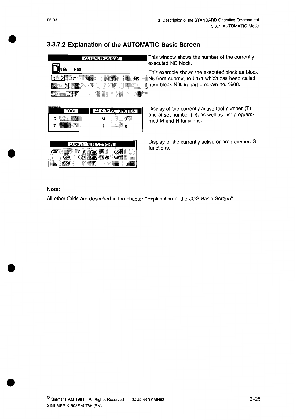
06.93
Description
3
of
the
STANDARD
3.3.7
Operating
AUTOMATIC
Environment
Mode
3.3.7.2
1466
rr~gi
ULLLSI'
D
T
;
GOO;
G60
r
G50
Note:
Explanation
ACTUAL
N60
L471
i
”
•
AUX./MISC.FUNCTIONM
I
Q
CURRENT
G16
G71
G
FUNCTIONS
G40
GSO
the
of
PROGRAM
PI
M
H
GS4
G90
G91
AUTOMATIC
This
executed
This
N5
NS
**
•:
p:.;
i
0
:i
from
Display
and
med
Display
functions.
Basic
window
NC
example
subroutine
from
block
of
offset
and
M
of
Screen
shows
block.
shows
N60
in
currently
the
number
functions.
H
currently
the
the
L471
part
(D),
number
executed
the
which
program
active
as
active
well
has
no.
tool
as
or
currently
the
of
as
block
called
been
%66.
number
last
(T)
program¬
programmed
block
G
All
other
fields
are
described
in
the
chapter
"Explanation
of
the
JOG
Basic
Screen".
©
Siemens
SINUMERIK
AG
1991
All
805SM-TW
Rights
(BA)
Reserved
6ZB5
440-0MN02
3-25
Page 61

06.93
4
Data
Introduction
4.1
Area
4
4.1
chapter
The
offsets,
ro
AREA
menu
4.2
To
select
lowing
picture
§1
AUTOMATIC
—
--
-
Data
Area
Introduction
Area"
"Data
data
transfers
tree.
Basic
the
Screen
data
area
displayed
is
-
:
—ÿ
explains
and
of
of
the
on
SKP
4F
how
to
diagnoses.
the
Data
SINUMERIK
the
CRT:
!
data
enter
chapter
This
Area
805SM-TW,
programs,
for
has
press
the
parameters,
same
operating
the
V.-ÿV.W
structure
RESET
as
area
tool
the
key.
offsets,
DATA
The
'
ze¬
fol¬
Notes:
When
•
The
•
SINUMERIK
menu
Siemens
the
data
tree
AG
1991
805SM-TW
area
is
All
(BA)
is
shown
Rights
selected,
in
the
Reserved
.|R
LED
the
chapter
6ZB5
&
l~‘f.
in
the
"Control
440-0MN02
,
SKSg
operating
Elements
II
CtyTEVFACES
on.
area
and
is
key
Operating
P'AGWOSIS'
Areas".
4-1
Page 62

4
4.3
Data
Program
Area
06.93
4.3
When
you
screen
is
m
AUTOMATIC
!
MM
MU
’imm
Program
press
displayed:
WM
\
so.
the
PROGRAM
./Mat
softkey
SKP
DRY
1
IAIN
PROCRAKFOR
in
the
ROV
*
PROGRAM
basic
DIRECTORY
PART
WMSM
—
screen
DBL
COMMENTS.
0062
670
M01
of
Ot
the
FST
data
RE'
area,
the
following
:
,a.
I
screen
This
switch
RECTORY.
The
10
NEXT/PREVIOUS
Selection
In
manually
•
between
directory
lines.
main
the
Manual
With
main
Use
lighted
If
of
or
the
program,
the
"astir
1
gives
you
MAIN
of
the
the
screen
PAGE
a
program
program,
the
with
selection
NEXT/PREVIOUS
cursor
selected).
=
:
’SI1
.....
i:
directory
a
PROGRAM
first
screen
is
full,
keys.
the
in
subroutine
SEARCH
subroutine
keys
to
select
further
......
all
of
DIRECTORY,
displays
directories
directory
cycle
or
softkey.
cycle.
the
keys,
desired
PAGE
or
stored
main
number,
will
directory,
select
program
SUBROUTINE
length
SL,'
programs.
and
displayed
be
you
can
directory
the
or
cycle
ffj-r.
means
By
DIRECTORY
comments
pressing
by
select
the
display
within
softkey,
of
and
the
of
the
desired
containing
directory
a
"
'
Ss?'
you
CYCLE
program
program
the
display
1
can
DI¬
max.
in
either
desired
(high¬
4-2
©
Siemens
AG
1991
All
Rights
Reserved
SINUMERIK
440-OMN02
6ZB5
805SM-TW
(BA)
Page 63
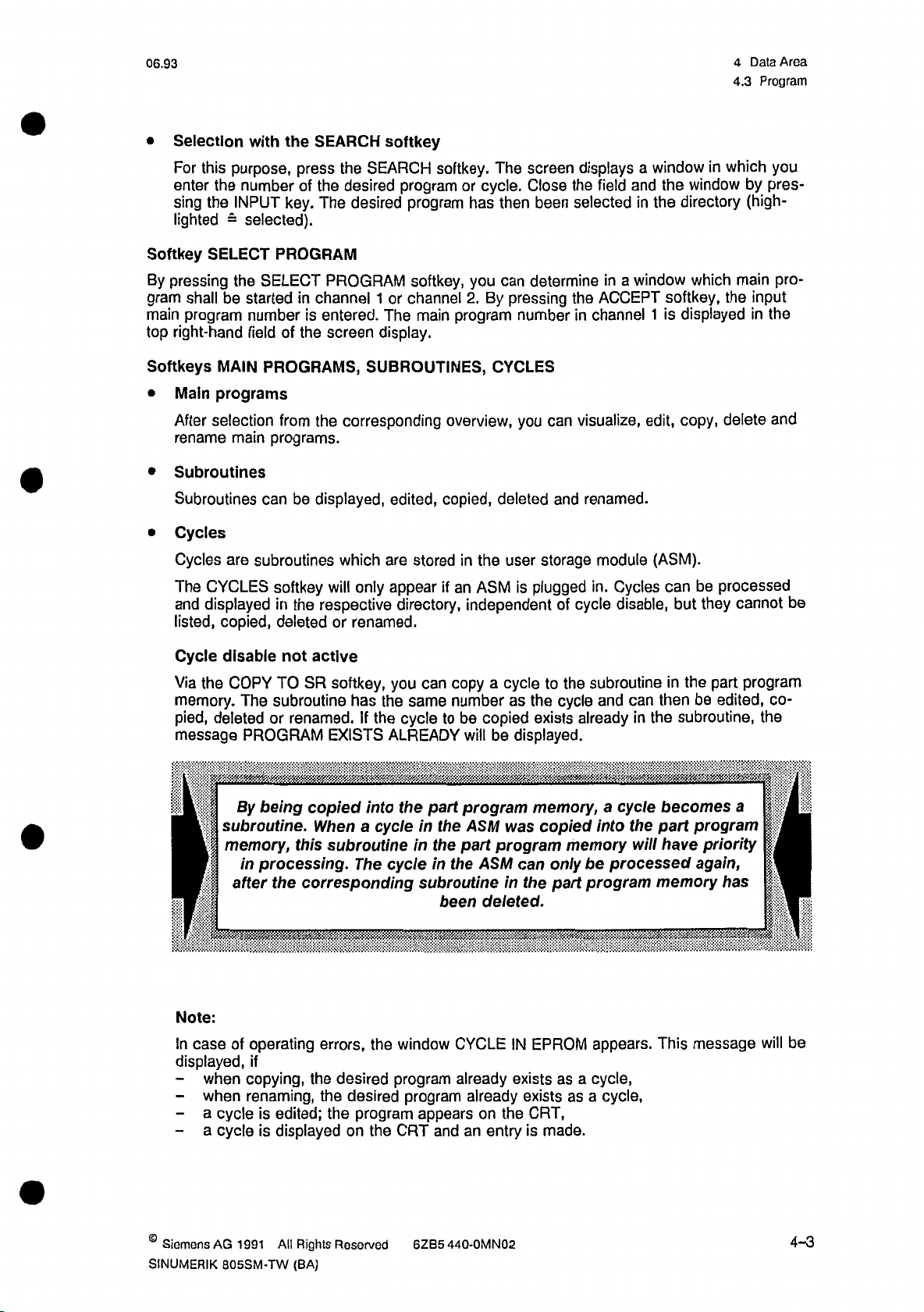
06.93
4
4.3
Data
Program
Area
Selection
•
For
enter
sing
lighted
Softkey
pressing
By
shall
gram
main
program
right-hand
top
Softkeys
Main
•
After
rename
Subroutines
•
Subroutines
Cycles
•
Cycles
The
and
listed,
with
this
purpose,
the
number
the
INPUT
selected).
=
SELECT
the
be
started
number
field
MAIN
programs
selection
main
are
subroutines
CYCLES
displayed
copied,
the
SEARCH
press
the
the
of
desired
key.
The
PROGRAM
in
of
the
from
be
is
PROGRAM
channel
entered.
screen
corresponding
the
displayed,
SELECT
PROGRAMS,
programs.
can
which
softkey
in
deleted
the
respective
will
or
softkey
SEARCH
softkey.
program
1
or
The
program
softkey,
channel
main
desired
display.
SUBROUTINES,
overview,
only
edited,
are
appear
copied,
stored
if
directory,
renamed.
The
cycle.
or
has
then
you
can
pressing
By
2.
program
number
CYCLES
you
deleted
in
user
the
an
ASM
is
independent
been
displays
the
selected
screen
Close
determine
the
in
visualize,
can
renamed.
and
storage
plugged
cycle
of
a
and
field
in
a
window
in
ACCEPT
channel
module
Cycles
in.
disable,
window
the
directory
the
softkey,
displayed
1
is
edit,
copy,
(ASM).
can
but
which
in
window
which
the
delete
be
processed
they
by
pres¬
(high¬
main
input
the
in
cannot
you
pro¬
and
be
Cycle
disable
Via
memory.
pied,
COPY
the
deleted
message
I
i
subroutine.
I
I
memory,
1
after
f
Note:
In
case
of
displayed,
when
-
when
-
a
cycle
-
a
cycle
-
not
SR
TO
The
subroutine
or
renamed.Ifthe
PROGRAM
By
being
this
processing.
in
corresponding
the
operating
if
copying,
renaming,
edited;
is
displayed
is
active
has
the
--
'
into
a
cycle
The
.
the
desired
program
on
the
you
cycle
ALREADY
the
cycle
window
program
CRT
softkey,
EXISTS
copied
When
subroutineinthe
errors,
desired
the
the
the
copy
can
same
numberasthe
to
:
part
in
the
in
the
subroutineinthe
been
CYCLE
already
program
appears
and
cycle
a
copied
be
will
be
'
program
was
ASM
program
part
ASM
deleted.
already
the
on
entry
an
to
the
cycle
exists
displayed.
•
memory,
copied
memory
only
can
part
IN
EPROM
as
exists
as
exists
CRT,
is
made.
subroutine
can
and
already
be
in
a
cycle
into
the
will
processed
program
appears.
cycle,
a
a
cycle,
the
in
be
then
subroutine,
the
becomes
program
part
have
again,
memory
message
This
part
edited,
W;.'
V./l
a
priority
has
program
co¬
the
be
will
©
Siemens
SINUMERIK
AG
1991
805SM-TW
All
Rights
(BA)
Reserved
6ZB5
440-0MN02
4-3
Page 64

4
4.3
Data
Program
Area
06.93
Cycle
With
The
fucntions.
system
program
CLE
While
PROGRAM
Notes:
After
•
functions
disable
cycle
disable
message
For
checks
number
IN
EPROM
a
cycle
softkey.
having
are
|
active
CYCLE
the
whether
is
extended
available:
OE
These
The
•
lected
With
•
with
drill
MULTIPLE-PURPOSE
functions
following
by
the
the
modules
chapter
the
cursor,
function
WOODSTEP®
and
being
active,
DISABLE
functions
the
or
new
the
will
processed,
are
displayed.
be
The
the
|
OflETEJ
described
describes
and
same
softkey
1
how
WOODSTEP
Editor.
configure
MACHINE
you
will
COPY,
desired
program
the
current
applies
texts
RENAME
the
in
the
to
create
EDITOR
Furthermore,
drill
units.
TOOLS.
cycles
cannot
be
copy
displayed
if
you
SUBROUTINES
block
to
with
j
a
your
the
already
coincides
is
not
correction
key
the
MOVE
'
sequence
DIN
program.
new
can
you
can,
function
EDITOR,
create
program
number
above
function
This
subroutines
to
try
to
and
RENAME
as
exists
with
displayed
block
H
ORGANIZE
the
in
i.e.
NC
the
with
described
is
nor
execute
a
the
after
display.
*
following
how
part
one
SUBROUTINES,
If
cycle.
the
cycle,
pressing
following
the
AVOCATION
I'
chapters.
edit
to
programs
in
the
technology,
user
WOOD
cycles.
edit
these
of
destination
the
message
the
jj
program
a
and
manual
the
CY¬
ACTUAL
'
SEARCHÿ
se¬
STEPs
define
of
4.3.1
Operating
|
Precondition:
DIN
EDITOR
DIN
EDITOR
Sequence
SI
The
the
Press
played:
Program
program
MAIN
the
Open
Number
be
to
edited
PROGRAM/SUBROUTINE
DIN
EDITOR
softkey.
program
should
SO
already
DIRECTORY.
following
The
IS
selected
be
window
from
is
dis¬
4-4
©
Siemens
AG
1991
All
Rights
Reserved
SINUMERIK
440-OMN02
6ZB5
805SM-TW
(BA)
Page 65

06.93
m
you
When
program
you
press
control
wanttocreate
number
the
INPUT
goes
into
in
the
the
key,
edit
a
new
window
the
mode.
program,
OPEN
field
input
4.3.1
the
enter
PROGRAM.
closed
is
4
Data
EDITOR
DIN
desired
When
the
and
Area
AUTOMATIC
HPFSQ
(PART
R100=1620
0050
(
R3=10
0050
(DRILLHOLE
R52=26
1/4990)
Lp
/4991)
R49=l
LF
R53=0
SKP
I)
Lp
R101=450
Lp
Rl=5
ON
TOP/4991)
R54=0
our"
|
R102=190
R31=1000
Lp
R55=0
j
ROV
EDIT
R103-5
R32=0
R56=0
|
DBL
PROGRAM
L4900
L4907
R57=0
\\
MOI
|~FST
PROGRAM
INSERT
Lp
Lp
L4905
Lf
-
-
IS
RUNNINI
in
REPLACE
Is®
:
Iff
Notes:
You
•
Press
•
are
Press
serted
softkey
To
•
can
the
overwritten
the
move
edit
REPLACE
INSERT
before
texts,
the
a
cursor
program
the
by
softkey
the
character
etc.
I
(e.g.
softkey
input
the
to
a
%50)
while
change
to
characters.
change
to
selected
desired
place
into
by
ESS
another
into
the
Then
the
cursor.
the
the
in
"
i.e.
the
the
,w|
%28)
the
in
input
page
is
existing
the
displayed
is
or
.....
1
program
replace
INSERT
mode,
insert
Then
program,
(e.g.
mode,
displayed
is
i.e.
REPLACE
use
,i,K.
running.
characters
softkey
characters
in
cursor
keys.
texts.
are
the
:
in¬
©
Siemens
SINUMERIK
AG
All
1991
805SM-TW
Rights
(BA)
Reserved
6ZB5
440-OMN02
4-5
Page 66

4
Data
4.3.1
Area
DIN
06.93
EDITOR
INSERT
BLOCK
DELETE
BLOCK
UNDO
IS
SEARCH
SEARCH
B
SI
Inserting
sor.
Deleting
The
ble
By
the
When
appears:
mm
of
of
changes
last
long
as
pressing
storage.
you
FOR
new
block
the
the
block
selected
the
in
INPUT
INPUT
the
SEARCH
after
block
key
key,
a
a
as
press
CHARACTER
block
the
the
are
undone.
has
not
block
softkey,
cursor.
by
the
STRING
IfS
selected
yet
change
the
|
This
been
is
following
by
the
only
is
pressed.
possi¬
entered
window
cur-
into
S
Notes:
The
•
subroutines:
The
•
...ÿ
program
input
M17).
program
can
LF
LF
must
be
be
edited,
Enter
the
field.
you
When
control
string.
You
block
concluded
as
and
can
must
described
character
the
press
cursor
the
now
enter
be
concluded
"Program
with
the
in
string
INPUT
blockbyblock
chapter
be
to
key,
positioned
is
with
end"
"DIN
the
(main
searched
entry
the
the
on
the
with
key
0
programs:
EDITOR".
opened
in
the
accepted
is
input
keyboard.
M02,
input
by
character
Each
M30
the
and
4-6
©
Siemens
AG
1991
All
Rights
Reserved
SINUMERIK
440-0MN02
6ZB5
805SM-TW
(BA)
Page 67

06.93
4.3.2
Part
Program
4
Memory
Area
Data
Allocation
4.3.2
To
MEMORY
Operating
obtain
Part
information
ALLOCATION
Precondition:
S
Program
about
MEMORY
ALLOCATION
Memory
the
softkey
Available
Occupied
Free
Allocation
status
of
the
program
in
the
The
MAIN
DIRECTORY
press
First
TION
softkey.
Part
Program
program
part
directory
PROGRAM
screen
MORE
the
The
memory,
screen.
DIRECTORY
should
key
following
Memory
B
Characters
Characters
32763
•
433,tÿUcharacte
•
:
1206$
already
and
window
then
press
the
SUBROUTINE
or
selected.
be
MEMORY
the
opened:
is
rs
ALLOCA¬
0
Note:
you
When
described
select
above,
the
with
menu
basic
available,
To
close
screen
of
DATA
the
occupied
the
is
restored.
and
window,
TRANSFER,
free
press
memory
RECALL
the
part
the
space,
program
is
also
key.
The
memory
displayed.
previous
status
©
Siemens
SINUMERIK
AG
1991
All
805SM-TW
Rights
(BA)
Reserved
6ZB5
440-0MN02
4-7
Page 68

4
Data
4.3.3
Area
Copying
Part
06.93
Program
4.3.3
You
function.
Operating
Precondition:
can
Copying
copy
El
Part
an
available
Sequence
COPY
Program
program
The
respective
First
following
Source
Dost
SI
a
to
desired
press
Copy
Program
illation
with
file
program
directory.
MORE
the
window
Mo.
Program
another
should
key
opened:
is
Program
No.
program
already
and
then
number
selected
be
COPY
the
153
using
softkey.
the
in
copy
the
The
Enter
the
destination
te
copy
the
4.3.4
Operating
Precondition:
Deleting
El
function.
Sequence
DELETE
(
program
Part
Program
SI
number.
The
respective
First
The
Program
Press
desired
directory.
press
the
following
Delete
No.
INPUT
the
program
MORE
window
key
should
and
key
opened:
is
conclude
to
already
then
153
the
m
selected
be
DELETE
the
entry
execu¬
and
the
in
softkey.
Enter
the
conclude
4-8
program
the
entry
number
and
execute
of
the
part
the
program
delete
be
to
function.
Siemens
deleted.
AG
1991
Press
Rights
All
INPUT
the
Reserved
SINUMERIK
key
to
6ZB5
805SM-TW
440-0MN02
(BA)
Page 69

06.93
4.3.5
Renaming
4
Part
Data
Program
Area
4.3.5
Using
|
Operating
Precondition:
Renaming
the
RENAME
0
Enter
function.
the
new
function
Sequence
RENAME
program
Part
you
Old
HI
number.
Program
change
can
The
desired
respective
press
First
following
The
Rename
Program
Program
Press
»o.
Jlo.
the
the
program
directory.
MORE
the
window
Program
INPUT
program
should
key
is
key
to
number
already
and
then
opened:
conclude
of
0
the
a
part
selected
be
RENAME
the
entry
program.
in
softkey.
and
execute
the
the
4.3.6
With
program
1)
2)
Operating
the
memory.
When
edited
When
Moving
MOVE
you
must
you
Precondition:
0
Part
function,
This
want
to
be
movedtothe
want
to
Sequence
MOVE
Program
the
necessary
is
a
program
edit
a
program
edit
selected
end
The
respective
First
function
program
the
in
while
of
memory.
and
desired
press
is
is
following
another
you
will
program
directory.
MORE
the
executed
appended
cases:
program
adding
be
should
key
without
the
to
executed,
is
more
already
then
and
display
last
then
*
the
of
program
the
1500
i
be
selected
MOVE
message.
a
part
in
the
program
characters
to
the
in
softkey.
be
to
The
it.
©
Siemens
SINUMERIK
AG
1991
All
80SSM-TW
Rights
(BA)
Reserved
6ZB5
440-OMN02
4-9
Page 70

4
Data
4.3.7
Area
Reorganizing
Part
Program
06.92
Memory
4.3.7
When
account
Using
gained
also
|
Operating
Reorganizing
programs
the
by
the
REORGANIZE
through
Alarm
No.
Precondition:
REORGANIZE
Note:
can
You
display
ALLOCATION
are
deleted
memory
deleting
31:
No
Sequence
and
control
softkey.
Part
from
allocation.
function
of
programs
further
part
the
Program
memory,
the
you
can
can
program
The
MAIN
already
reorganize
To
Memory
rearrange
be
now
input
PROGRAM
be
selected.
REORGANIZE
gram
Memory"
reorganizing
the
when
available,
occupied
free
the
the
used
possible).
program
the
softkey.
message
and
memory
program
for
or
is
memory.
storage
of
SUBROUTINE
memory,
"Reorganizing
displayed
is
running.
free
is
memory
routine
automatically
not
new
the
directory
press
Part
the
on
space
memory
The
programs
the
Pro¬
CRT
the
with
into
taken
(see
should
MEMORY
4.4
Operating
DATA
PARAMETERS
&
R
R
R
R
R
R
R
R
R
R
R
R
R
R
R
Data
0
1
2
a
4
5
6
7
8
9
10
11
12
13
14
and
Parameters
Sequence
rfllifl::;!
JO
27
.
.
0.0
3:0
:Q:O;?I
;;
1000:0*1
1000.0
0.0
8.0
8.0
100.0
48.0
118.
When
lowing
;i
I
M
I
|
I
i
:i
0
I
you
press
screen
PARAMETERS
R
u
DATA
the
displayed:
is
R
R
R
R
R
R
R
R
R
R
R
R
R
R
R
15
16
17
18
19
ZO
21
22
23
24
25
26
27
28
29
PARAMETERS
&
220.5
3S.0
BO.fl
;Q.O
3.0*1
?nfln;o
31.0
0.0
o:o'
0*0
OvO
mm
mm
0.0
softkey,
•
I
:|
>
I
:|
I
the
fol¬
BE
Basic
screen
4-10
for
Data
sari
and
Parameters.
>HCH
I
f%s°
©
Siemens
I
AG
1
991
All
Rights
Reserved
SINUMERIK
Sf
440-0MN02
6ZB5
805SM-TW
(BA)
Page 71

06.93
Notes:
4.4
Data
4
Data
and
Parameters
Area
The
The
The
selected
basic
movable
•
•
•
4.4.1
The
parameters
R
RO
to
R699
RO
to
R699
R700
to
R999
Notes:
You
•
•
Selecting,
•
•
•
•
will
Programming
The
R
ment.
The
R
keys)
You
can
For
R
Press
Press
data
screen
field
R
Parameters
are
parameters
R
R
parameters
Central
summary
a
find
Instructions,
parameters
altering
parameters
or
pressing
by
the
alter
parameters,
the
DELETE
the
START
type
is
of
DATA
is
displayed
subdivided
parameters
R
channel
for
and
deleting
can
be
the
parameter
R
you
can
AREA
softkey
in
displayed
&
PARAMETERS
in
into
for
channel
channel
for
of
R
the
SINUMERIK
2
R
selected
SEARCH
valuesasdescribedinthe
also
softkey
to
execute
inverse
darker
parameters
color.
channel-specific
1
2
(channel
805SM".
cannot
parameters:
use
be
manually
softkey
the
pocket
delete
to
the
function.
video.
shows
and
1
their
and
displayed
(with
the
(enter
R
calculator
R
parameter
the
parameter
R
and
central
channel
2)
allocation
altered
and
of
help
parameter)
chapter
function.
area.
parameters,
and
the
via
cursor,
the
and
the
"Entries
areas.
Enter
as
function
operating
home
INPUT
in
the
follows:
in
the
environ¬
and
key.
Fields".
Input
desired
"NC
page
area.
©
Siemens
SINUMERIK
AG
All
1991
805SM-TW
Rights
(BA)
Reserved
6ZB5
440-0MN02
4-11
Page 72

4
4.4.2
Data
Area
Sotting
06.93
Data
4.4.2
following
The
The
•
The
•
The
•
The
•
Operating
|
SETTING
DATA
Setting
defined
is
working
dry
run
feed
workpiece
spindle
data.
Sequence
WORKING
MIN.
X
Y
z
Data
area
related
activated
or
limitation
rate.
actual
AREA
the
for
value
When
window
MAX.
by
means
individual
display
you
is
SETTING
:1
setting
of
axes.
system.
press
the
displayed:
DATA
RUN
DRY
WORKPIECE
SPEED
LIMIT
PROQR.
SPINDLE
EXACT
FEED
ACCELERATION
data:
SETTING
GENERAL
RELATED
SPINDLE
LIMIT
SPEED
STOP
DATA
ACT.
(G92)
9)
(Ml
RAMP
softkey,
DATA
VALUE
DATA
TIME
SYSTEM
FOR
THREADS®ÿ
following
the
MMM
mm
4-12
BM
SETTING
M
\
NCMD
l4<Hliill
NCMD
BFTS
mini
©
Siemens
I
AG
1991
PLCMD
All
iVll
H
ADAPTED
:
FEEDRATE
M
M<lUIIMIHMMtlHI><4»i
Rights
Reserved
SINUMERIK
6ZB5
805SM-TW
:
S
v
x
<
440-OMN02
(BA)
Page 73

06.93
The
following
table
shows
the
input
value
range
for
parameters.
the
4.4.2
Data
4
Setting
Area
Data
Description
1st
1st
5th
5th
Run
Area
Axis
Axis
Axis
Axis
Data
Feed
Data
Limit
Working
Min.
Max.
Min.
Max.
General
Dry
Spindle
Speed
Progr.Speed
Exact
Spindle
Feed
Accel.
Limit
Rate
Limit
Stop
Ramp
(G92)
(M19)
Time
for
Threads
Standard
Values
0
0
0
0
0
0
0
0
0
Maximum
Value
Input
99999999
±
99999999
±
99999999
±
99999999
±
60000
24000
24000
359.9
5
Input
Unit
0.001
0.001
0.001
0.001
m/min
1/min
1/min
1/10
mm
mm
mm
mm
2)
3)
3)
Degree
1)
1)
1)
1)
Workpiece
When
the
are
sets
The
1)
2)
3)
taken
workpiece
input
The
The
input
The
input
Related
workpiece
into
account
zero
defined
unit
is
is
defined
unit
unit
defined
is
Actual
related
Value
actual
in
becomes
by
the
by
the
by
the
System
value
actual
the
reference
the
machine
machine
machine
value
data!
data!
data!
system
point
can
It
can
It
can
It
selected,
is
display.
for
0.0001
be
m/min
be
bo
1/min
the
actual
mm,
or
mm/min.
0.
or
the
0.001
1lmin
zero
value
mm,
(see
offsets
display.
or
0.01
documentation).
OEM
and
mm.
the
tool
off¬
©
Siemens
SINUMERIK
AG
1991
805SM-TW
All
Rights
(BA)
Roserved
6ZB5
440-0MN02
4-13
Page 74

4
Data
4.4.2
Area
Setting
09.91
Data
or
the
enter
§
Changing
change
To
0
To
activateordeactivate
0
|~4-|
|
Setting
setting
1)
2)
»|
—
Data
data,
The
"Max.
The
"Input
1lmin
the
"Workpiece
proceed
Input
or
0.1
Select
Unit
/mini
as
described
Value”
is
specified
"
Related
respective
the
specified
is
Actual
the
in
by
input
chapter
by
the
Value
field
the
MD:
it
System",
using
"Entries
MD
!
can
be
do
cursor
the
Reids".
input
in
m
following:
the
keys.
Note:
When
0
0
Workpiece
Workpiece
press
you
related
related
the
HOME
actual
actual
key
Press
The
value
value
0
PLUS
status
system
system
of
the
for
activate
to
the
is
off
on
is
upper
the
or
function
m
left
axis).
X
MINUS
is
field
to
indicatedinthe
selected
is
deactivate
input
(Working
the
field.
area
function.
limit
4-14
©
Siemons
AG
1991
All
Rights
Reserved
SINUMERIK
440-0MN02
6ZB5
805SM-TW
(BA)
Page 75

06.93
4.4.3
4
Adapted
Area
Data
Feedrate
4.4.3
I
Operating
ADAPTED FEEDRATE
Notes:
The
•
Adapted
Sequence
ADAPTED
Feedrate
Adaption
contour
Max.
Minimum
FEEDRATE
When
lowing
Adapted
active
feedrate
function
you
picture
error
will
press
is
feedrate
available
be
ADAPTED
the
displayed:
as
!i
FEEDRATE
from
software
softkey,
version
3.
the
fol¬
When
•
will
The
menu
4.4.4
selection
After
ta
types
sioning.
the
PLUS/MINUS
be
activated
parameters
or
preselected
NC-MD
of
will
appear.
key
is
deactivated.
or
MAX.
CONTOUR
program
a
via
Values/NC-MD
desired
the
These
data
data
are
pressed
in
ERROR
(see
Bits/PLC-MD
by
type
means
exclusively
ADAPTION
the
MINIMUM
and
PROGRAMMING
NC
the
corresponding
of
for
used
the
ACTIVE
input
FEEDRATE
GUIDE).
purpose
of
field,
can
softkey,
service
be
a
and
function
the
input
list
of
commis¬
in
the
this
da¬
©
Siemens
SINUMERIK
AG
All
1991
805SM-TW
Rights
(BA)
Reserved
6ZB5
440-0MN02
4-15
Page 76

4
4.5
4.5
Data
Tool
Area
Offset
Tool
06.93
Offset
::
1
71
The
tool
parameters.
Operating
Precondition:
TOOL
OFFSET
Pi
AUTOMATIC
It
offsets
The
Sequence
Use
of
basic
the
only
SINUMERIK
the
menu
tools
of
the
When
picture
specified
805SM-TW
TOOL
are
You
in
you
is
ySvftvtvvwl;
TOOL
by
the
are
OFFSET
the
data
press
displayed:
ROV
DBL
OFFSET
machine
storedinthe
is
selected
area.
TOOL
the
M01
111
manufacturer!
offsets
tool
follows:
as
OFFSET
\
RESET
D1
softkey,
I
to
the
under
D999
following
I
.v.r.?ÿ
.
.
.
.
.
Notes:
The
•
Depending
•
dual
OFFSET
NUMBER
NUMBER
TOOL
TOOL
TYPE
LENGTH
LENGTH
RADIUS
1
2
i
.1..
SINUMERIK
offsets
L5WMIIRV
805SM-TW
upon
selected
is
displayed.
OFFSET
BLOCK
OFFSET
J
S
tool
DATA-
features
type
.
.
tool
a
picture
T
MilEOt
MKOX
offset
showing
Be.
***+.
numbers
,
from
location
Type
Tool
Type
Turning
cutting
Type
Tools
compensation
Type
Tools
and
(e.g.
Type
Tools
and
(e.g.
II
and
TOOL
0
defined
not
1..9
tools,
edge
10
effective
with
20
radius
with
length
one
milling
30
radius
with
length
two
angular
a.1ggj.
D99.
D1
to
explanation
cutters)
TYPE
of
position
length
only
compensation
compensations
head
drills)
(o.g.
compensation
compensation
cutters)
of
the
the
tool
indivi¬
4-16
Siomens
AG
1991
All
Rights
Reserved
SINUMERIK
440-0MN02
6ZB5
805SM-TW
(BA)
Page 77

09.91
4.5.1
Selecting
Tool
4
Data
Offset
Area
Number
4.5.1
There
a)
Operating
are
Using
Selecting
two
the
SB
b)
By
entering
Operating
0
Offset
Tool
ways
to
NEXT/PREVIOUS
Sequence
the
tool
Sequence
select
offset
the
Number
offset
tool
PAGE
the
With
number
offset
number
Select
key.
Press
keys
page
the
the
number
keys
(D
field
input
key
EDIT
manually:
you
can
number).
OFFSET
to
open
to
pass
NUMBER
the
field.
the
next
using
higher
the
or
lower
HOME
IS
4.5.2
Operating
|
Precondition:
To
Fields".
Deleting
delete/alter
Sequence
iSS
a
tool
Altering
and
m
parameter,
the
Enter
After
the
The
parameters
Tool
The
offset
should
proceed
desired
number
Parameters
number
already
always
be
as
offset
number
entered,
been
has
the
selected
of
the
where
selected.
describedinthe
using
the
press
number
offset
correction
chapter
number
the
has
to
"Entries
keys.
INPUT
displayed.
are
be
made
key.
in
Input
©
Siemens
SINUMERIK
AG
All
1991
805SM-TW
Rights
(BA)
Reserved
6ZB5
440-0MN02
4-17
Page 78
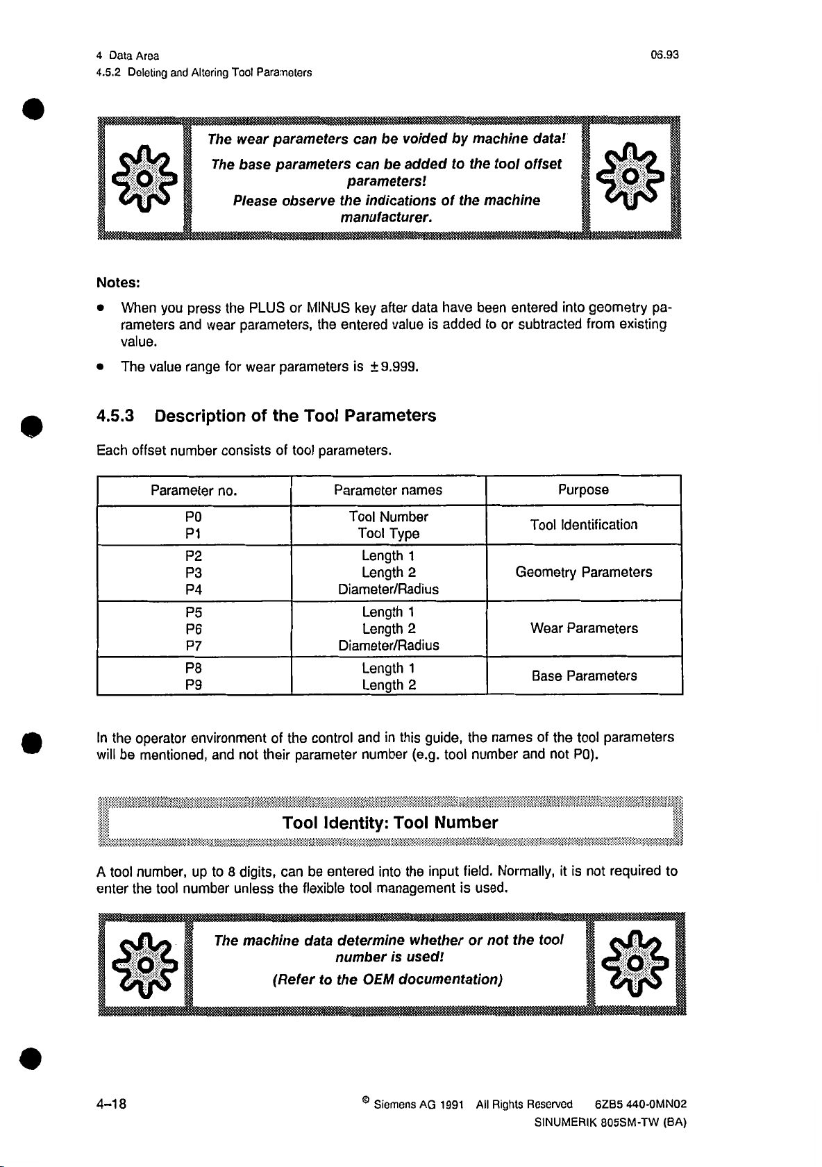
4
Data
4.5.2
Area
Deleting
and
Altering
Tool
Parameters
06.93
0
Notes:
When
•
rameters
value.
The
•
4.5.3
Each
you
press
and
range
value
Description
offset
number
Parameter
P0
P1
P2
P3
P4
P5
P6
P7
P8
P9
wear
The
The
Please
the
wear
for
consists
no.
base
parameters
parameters
observe
or
PLUS
parameters,
wear
of
MINUS
parameters
the
Tool
tool
of
can
be
be
can
parameters!
indicationsofthe
the
manufacturer.
key
after
the
entered
value
9.999.
is
±
Parameters
parameters.
Parameter
Number
Tool
Type
Tool
Length
Length
Diameter/Radius
Length
Length
Diameter/Radius
Length
Length
voidedbymachine
addedtothe
have
data
added
is
names
1
2
1
2
1
2
tool
machine
entered
been
or
to
Geometry
data'.
offset
into
subtracted
Purpose
Tool
Identification
Wear
Parameters
Base
Parameters
fgl
geometry
existing
from
Parameters
pa¬
the
In
will
tool
A
enter
$
4-18
operator
mentioned,
be
number,
the
tool
environmentofthe
and
up
to
number
The
not
digits,
8
unless
machine
their
can
the
(Refer
control
parameter
Tool
Identity:
be
flexible
data
to
and
number
entered
tool
determine
number
OEM
the
©
guide,
this
in
(e.g.
Tool
Number
input
the
into
management
whether
used!
is
documentation)
AG
Siemens
1991
tool
names
the
number
field.
is
used.
or
not
All
and
Normally,
the
Rights
Reserved
SINUMERIK
of
not
tool
the
it
parameters
tool
P0).
is
not
required
to
KH
440-0MN02
6ZB5
805SM-TW
(BA)
Page 79

06.93
1
mmmm
Data
4
Area
Description
4.5.3
r.;n
.
Identity:
Tool
,
wtmm
Tool
Type
mmmm
Tool
Type
of
msmm
Tool
the
Parameters
Tool
Type
with
with
length
shaft
length
radius
Tools
compensation
Example:
Drill
Tools
compensation
one
compensation
Example:
Vertical
only
and
cutter
:h
Radius
Length
Length
II
1
1
10
20
Tools
with
compensation
length
two
compensations
Example:
Angular
marks
Tf
©
Siemens
SINUMERIK
AG
805SM-TW
radius
head
1991
and
cutter
the
reference
Rights
All
(BA)
point
Reserved
Length
1
Radius
the
of
6ZB5
j
1
i
holder
tool
440-0MN02
F.
2
(reference
point
for
the
30
slide).
4-19
Page 80

Data
4
4.5.3
Area
Description
06.93
the
Tool
of
Parameters
mm
11
Enter
Enter
You
the
the
can
tool
cutter
enter
:
Mi,
w-V
-•
Geometry
Geometry
Geometry
at
geometry
radius
wear
these
input
The
S
values
value
Wear
Wear
Wear
values
parameter:
parameter:
parameter:
S
into
parameters
into
parameter
parameter:
parameter:
parameter:
into
ol
the
tool
locked
Check
by
the
Length
Length
Diameter
for
diameter/radius.
Length
Length
Diameter/Radius
parameters.
geometry
key
the
OEM
operated
documentation
length
The
and
1
2
1
1
2
entry
wear
Radius
/
length
and
wear
of
values
switch.
first!
2.
is
may
>2?
not
mm.
mandatory.
be
-1
This
The
parameters
tool
base
value
allows
Basic
Basic
are
intended
compensate
to
parameter:
parameter:
special
for
additional
for
Length
Length
1
2
applications.
length.
tool
I
I!
4-20
©
Siemens
AG
1991
All
Rights
Reserved
SINUMERIK
6ZB5
440-0MN02
805SM-TW
(BA)
Page 81

09.91
4.6
4
Data
Zero
Area
Offset
4.6
After
lue
display
The
"W”.
The
fixture
vary.
Zero
axes
the
are
program
part
machine
type,
When
Offset
have
referred
zero
the
distance
program
a
L
Y-
been
for
point
referenced,
the
to
machining
the
“M"
between
executed,
is
machine
workpiece
and
machine
this
!
IR=F
•J
of
the
zero
the
actual
point
workpiece
zero
zero
distance
value
"M".
point
point
is
taken
register
is
referred
"W"
"M"
into
and
are
not
workpiece
and
account
subsequently,
workpiece
the
to
identical.
zero
as
the
actual
the
point
zero
Depending
point
"W"
zero
offset.
va¬
upon
may
YMR
Zero
P
M
W
R
F
WR
XMR,
XMW,
offset
YMR
YMW
1
T
YMW
on
,
milling
a
M
4
XMR
machine.
Tool
Machine
Workpiece
Machine
Slide
Workpiece
Reference
Zero
p
XMW
setting
point
zero
zero
reference
reference
reference
point
offset
point
point
point
point
point
coordinates
:c
W
|
!
WR
*
X
©
Siemens
SINUMERIK
AG
1991
All
805SM-TW
Rights
(BA)
Reserved
6ZB5
440-0MN02
4-21
Page 82

4
4.6
Data
Zero
How
Area
Offset
to
Select
Zero
06.93
Offset
Precondition:
ZERO
OFFSET
•
zo
.
,
:
zo
FINE
ZO
m
G56
mm
6571
IS
NV
FINE
ZO
•'
zo
FINE
ZO
zo
ZO
FINE
M
ZO
'
PROG.
zo
EXTERN
PROG.
The
Press
data
the
area
ZERO
should
OFFSET
already
be
softkey.
selected.
following
The
picture
is
displayed:
OFFSET
ZERO
X
;
6.000
h
|aa0.00a
l»o.oqoHl
6.000
I
0.000
I
6.000
I
6.000
I
0600
1
0.000
0.000
„
0.000
1
I
I]I
I
I
I
I
|>
I
i
I
I
I
Q.fr6Q
o.ooo
0.006
0.000
0.000
:
0.000
0-000
0.000
0.000
0.000
j
i
I
)
I
1
1
I
I
I
I
[
I
I
1
I
6.660"'
0-flQQ
04)06
I
o.ooa
:
0.006
0.006
6.000
0.006
0.000
0.000
0.000
|
]
i
i
i
I
j
I
i
1
E
j
[
j
The
•
•
•
zero
total
Settable
Programmable
External
Notes:
this
In
•
•
•
•
•
The
You
turn
The
For
In
other
can
to
values
the
the
offset
zero
zero
menu,
zero
select
the
input
part
active
offset
zero
offset
values
are
the
initial
field
can
be
fields,
program,
an
in
G55,
(G54,
(G58
offset
EXTERN).
(ZO
can
only
displayed.
just
desired
(top
left
changed
you
can
can
you
is
axis
a
G56,
and/or
be
entered
input
fields
corner).
as
describedinthe
use
also
G53
with
of
sum
G57)
or
G59)
for
using
pocket
the
deselect
the
the
the
settable
cursor
chapter
all
following
zero
keys.
"Entries
calculator
zero
offsets
zero
offsets:
offsets
Press
in
function.
blockbyblock.
(G54
the
Input
to
HOME
Fields".
G57).
key
to
re¬
4-22
©
Siemens
AG
1991
All
Rights
Reserved
SINUMERIK
440-QMN02
6ZB5
805SM-TW
(BA)
Page 83

06.93
4.6
4
Data
Zero
Area
Ortset
Explanation
Settable
•
your
In
mands.
The
value
the
-
the
-
Programmable
•
Using
G58
on
how
(manufacturer
To
display
display.
Note:
G58
and/or
program
the
of
External
•
The
values
the
NC.
of
the
Offset
Zero
program,
of
the
coarse
fine
offset
offset
and
program
to
documentation
zero
the
G59
Offset
Zero
of
the
Offsets
Zero
you
can
settable
(ZO),
(ZO
Offset
Zero
G59,
you
these
offsets
values
deletes
external
call
zero
FINE)
can
zero
active
are
these
zero
up
offset
and
include
offsets
of
valid
values.
of
one
is
additional
are
SINUMERIK
the
in
the
for
only
(ZO
offset
the
4
sum
the
given
current
the
current
EXTERN.)
settable
of:
zero
offsets
in
the
805SM).
program,
program.
offsets
zero
your
in
"Programming
select
the
The
are
transferred
using
G54
program.
Instructions
ZERO
or
M02
the
from
to
G57
Indications
NC"
OFFSET
the
at
M30
PLC
com¬
end
to
The
external
ZO
is
also
displayed
in
the
ZERO
OFFSET
display.
0
Siemens
SINUMERIK
AG
1991
805SM-TW
All
Rights
(BA)
Reserved
6ZB5
440-0MN02
4-23
Page 84

4
4.7
Data
Data
Area
Transfer
06.92
4.7
the
Press
softkey.
m
Data
Transfer
INTERFACES
following
The
JOG
M
softkey
screen
INTERFACEl
is
|
SKP
,
mmmmmm
in
basic
the
displayed:
DRY
I
DAf
A
Part
available
occupiei
ree
menu
of
mv
faj
TRANSFER1
Program
.
i||
32768
:
4331
12053
Memor'
data
the
M01
II
Characters
Characters
Characters
area
fsT
and
I-
RE:
...
the
DATA
%28
RTS-LINE
TRANSFER
...
Notes:
In
•
allocation
Interface
•
For
•
the
further
basic
chart
2
is
information,
menu
showing
only
DATA
the
of
the
operative
see
TRANSFER,
available,
the
with
chapter
the
can
you
occupied,
corresponding
"Data
and
Interfaces".
the
see
free
supplement.
part
memory
program
space.
t:~ri
memory
4-24
©
Siemens
AG
1991
All
Rights
Reserved
SINUMERIK
440-0MN02
6ZB5
805SM-TW
(BA)
Page 85

06.92
4
4,8
Area
Data
Diagnosis
4.8
Press
displayed:
Diagnosis
the
DIAGNOSIS
NO.
softkey
.EQ.
in
the
ILOCI
basic
AI
menu
of
iAi
the
data
COMMENT
area.
The
following
picture
is
lUiaibH
Note:
having
After
available:
are
[
4.8.1
the
In
alarms
MESSAGES
Notes:
•
•
All
DIAGNOSIS
and
The
selected
screen.
alarms
The
chapter
the
IMAISTI;
extended
the
P
Messages,
basic
messages
PLC
softkeys
you
group
alarm
are
which
"Monitoring".
ALARMS
softkey
8
NC/PLC
screen,
displayed.
are
differentiate
can
is
possibile
PLC
texts
ll
with
Alarms,
messages
all
With
highlighted
SINUMERIK
in
the
'
STÿTCUS
MESSAOEs"
the
|
key
_
Messages
PLC
selected,
are
ALARMS,
NO
the
accordingly.
in
the
softkey
texts
805SM-TW
|[ÿSERÿCE''""|"'
,
following
the
I
all
PLC
and
arising
are
i.e.
ALARMS
is
displayed
listed
functions
alarms,
NO
and
in
and
QUIT
v.™-
PLC
PLC
menu
the
described
|
I
I
in
pressing
By
•
©
Siemens
SINUMERIK
the
AQ
1991
805SM-TW
OUIT
Rights
All
(BA)
softkey,
Reserved
you
acknowledge
can
440-OMN02
6ZB5
alarms
messages.
and
4-25
Page 86

4
Data
4.8.2
Area
PLC
06.92
Status
4.8.2
PLC
the
In
operands:
the
displayed
Operand
inputs
Outputs
_Fjags
Timers
Counters
block
Data
word
Data
PLC-Status
operating
inputs,
changed
or
system,
outputs,
Example
:
I0.0
IB
2
2
IW
0.1
Q
QB
QW
F
0.7
FY
FW
DB3
as
20
20
60
60
DW9
a
flags,
follows.
Read
PLC
Yes
Yes
Yes
Yes
Yes
Yes
status
timers,
Write
is
available
counters
Yes
Yes
Yes
No
No
Yes
as
and
Format
B
B
H
D
B
H
D
B
B
H
D
B
H
D
B
B
H
D
B
H
D
B,
H,
H,
B,
B
H
D
a
service
data
D
D
words
0101
1101
1011
0000
and
test
data
of
Value
0101
1100
1010
1101
1100
0110
1011
0100
0100
0000 0000
aid.
In
blocks,
1010
5A
90
0011
5AC3
23235
0110
D6
214
0011
D6C3
40379
0100
B8
180
0000
B880
47232
1010
10
0
1
0
A
this
can
mode,
be
Area
0-127
0-127
0-255
0-31
0-31
0-255
0-255
Notes:
B
The
Maximally
4-26
binary,
=
operands
H
in
operands
10
hexadecimal,
=
PLC
status
can
D
canceled
are
displayed
be
decimal
=
when
at
©
Siemens
a
the
time.
AG
control
1991
is
All
switched
Rights
off.
Reserved
SINUMERIK
6ZB5
440-0MN02
805SM-TW
(BA)
Page 87

06.92
|
is
How
to
Select
the
Operand
4.8.2
4
Data
PLC
Area
Status
Precondition:
AUTOMATIC
Operand
JEW
_
Ml
m
iiil
m
m
m
§
Format
j
m
iH
m
m
m
wm
EDO
in
m
by
"
SKP
PLC
The
means
DRY
1
VALUE
STATUS
corresponding
the
of
||
ROV
PLC
STATUS
DBL
menu
M01
should
softkey.
'
already
RESET
'
selected
be
_
|HE)TyÿÿInputbitTH|
byte
DWy
Input
Input
Flag
output
Timer
Counter
Data
,V;":
word
out
Hg|l
H
H|
x
EB
x
EW
|H
H
...
HA...
T
x
ffl
Z
x
DBx
|H
i
D
I
Decimal
t
Note:
help
the
With
or
the
format
Example:
cursor
The
increase
key
to
©
Siemens
SINUMERIK
AG
i
m
the
of
ascending
in
in
column
is
the
All
1991
805SM-TW
Position
enter
OPERAND
Fields".
Input
Then
field.
input
separate
displayed
the
the
enter
cursor
desired
input
the
For
each
number
in
the
INCREMENT/DECREMENT
or
OPERAND
operand
Rights
Reserved
(BA)
descending
101.
AB
to
in
6ZB5
sequence
occupied
an
440-0MN02
on
operand
field,
desired
operand
notation.
VALUE
keys,
you
and
line,
line,
(e.g.
using
a
according
number
or
The
field.
can
pass
select
the
AB
here:
the
IW
2
=
the
to
notation
line,
each
status
of
through
desired
Press
100.
cursor
Input
chapter
in
the
you
operand
the
an
setting.
the
Then
keys.
2)
word
"Entries
in
in
FORMAT
can
choose
is
then
operand
field
INCREMENT
the
a
4-27
Page 88

4
Data
Area
PLC
4.8.2
HowtoAlter
Status
the
Value
06.93
(Control)
Precondition:
|
|
|
HowtoDelete
[
the
HCD
DELETE
4.8.3
When
Service
press
you
Data
the
SERVICE
Operand
Display
The
Position
altered,
VALUE
the
Input
in
Position
using
DELETE
then
softkey,
desired
the
cursor
using
field
Fields".
cursor
the
cursor
the
Press
without
information
operand
on
the
cursor
desired,
as
(Pay
on
keys.
the
input.
on
the
keys.
already
VALUE
Then
should
according
attentiontothe
line
axes
to
softkey.
and
the
DELETE
the
be
field
change
be
deleted
the
selected.
of
the
the
the
to
selected
i
line
The
spindle
operand
contents
chapter
format.)
is
appear.
will
be
to
of
"Entries
SERVICE
Y
0
0
0
0
0
0
0
z
0
0
0
0
0
0
0
FOLLOWING
ABSOLUTE
POSITION
SPEED
PART
PARTCOMMANDVALUE
CONTOUR
ERROR
ACT.
COMMAND
COMMAND
ACTUAL
VALUE
DEVIATION
VALUE
VALUE
VALUE(VELO)
x
0
0
0
0
0
0
0
SPINDLET
(1/MIN)
COMMAND
SPEED
ACTUAL
SPEED
POSITION
CUTTING
'
fc
\
DRIFTcbiiRP
.................
VALUE
(1/MIN)
VALUE
(DEG)
VALUE
(G9«)
SPEED
EWFTCOMP
if
|
MUMMULMIHI
M<
IIM
111
111
1 1
DRIFTCOMp'
!
j
||
|>MIIMIIIIIIIIII»||MI|.
1
I
1 1
1
0
0
0
0
'
IIIIIIIIIIIHIIII
il.lil,
I
......
...
111
.............
1
II
Ml
ll
l.i
Jt
1
4-28
Siemens
AG
1991
All
Rights
Reserved
SINUMERIK
440-0MN02
6ZB5
805SM-TW
(BA)
Page 89

06.93
Notes:
When
•
is
The
•
described
you
press
performed.
values
displayed
in
softkey
the
Observe
are
corresponding
the
DRIFT
indications
the
analyzed
COMP,
by
of
the
the
the
machine
service
documentation.
drift
compensation
manufacturer.
commissioning
and
for
4.8.3
the
staff
4
Data
Service
Data
respective
are
and
Area
Display
axis
of
you
the
Version
4.8.4
When
key
Note:
Information
press
the
VERSION
DIAGNOSIS
initial
this
about
basic
softkey
screen,
screen
is
in
an
initial
given
the
softkey
screen
in
the
texts
displayed.
is
chapter
extended
"Control
means
by
ON/OFF".
of
the
MORE
®
Siemens
SINUMERIK
AG
All
1991
805SM-TW
Rights
(BA)
Reserved
6ZB5
440-0MN02
4-29
Page 90

4
4.9
Data
JOB
Area
LIST
06.93
4.9
4.9.1
With
specified
JOB
Introduction
the
JOB
sequence.
identifications
process
In
process,
specified.
In
the
automatically
memory.
This
storage
Notes:
•
•
JOB
the
LIST
JOB
external
feature
The
If
the
the
subroutine
is
started.
LIST,
how
mode,
mass
increases
(for
DG-SM
option
option
loaded
LIST
LIST
function
The
enteredbythe
are
can
you
they
often
you
storage
into
the
approx.
LIST
JOB
LIST
JOB
defined
you
max.
specify
should
can
also
devices.
control's
capacity
1
.4
must
is
available,
via
can
JOB
9
operator
part
be
repeated,
specify
memory,
MB).
be
available.
MD
NC
run
Orders,
programs
When
of
the
the
30.
several
consisting
the
in
and
orders
JOB
the
JOB
executed,
part
texts
programs
window
which
then
including
LIST
program
for
the
in
program
of
JOB
should
you
can
is
processed,
and
then
memory
PLC
a
number,
LIST
before
be
for
run
execute
programs
deleted
up
to
messages
the
a
the
which
these
from
capacity
the
must
size
lot
machining
certain
machining
sequence
are
programs
control’s
the
available
be
and
as
stored
are
the
of
in
mass
in
JOB
The
•
"Interface
a
After
•
If
•
window
4.9.2
4.9.2.1
Operating
Precondition:
JOB
JOB
the
in
Operating
Basic
0
JOB
LIST
LIST
function
Description,
order
has
active,
is
LIST
AUTOMATIC
the
Screen
Sequence
is
also
Part
been
the
mode
JOB
JOB
described
Signals".
1:
processed,
actual
program
because
LIST
LIST
The
data
Press
the
the
Press
displayed:
the
in
is
it
will
it
area
MORE
JOB
"Start-up
deleted
number
cause
should
key.
LIST
from
may
fault
nil
already
softkey.
Instructions"
the
not
during
be
The
LIST.
JOB
changed
be
processing
the
selected.
JOB
and
LIST
in
the
manually
of
screen
a
is
via
JOB.
the
4-30
©
Siemens
AG
1991
All
Rights
Reserved
SINUMERIK
440-0MN02
6ZB5
805SM-TW
(BA)
Page 91

02.94
4.9.2
Operating
4
the
Data
JOB
Area
LIST
AUTOMATIC
ACTIVE
Current
Ready
No.
No.
No.
No.
NO.
No.
No.
No.
No.
U
1
2
3
4
5
6
7
8
9
inter:
W
1
i
SKP
I
Wm
Prog.
'*13»
15
10
50
55
0
0
0
0
0
-
DRY
No.
:
ROV
11
iit
ii
i
iiiiii
LotSlZt
m
1
1
8
3
1
1
1
1
1
OBL
M01
m
M
II
I
II
......
FST
;;
.
PROGRAM
Tdeht.
1
2
1
0 0
0
0
0
0
!
2
W
1$
RUNNING
:L
’0
0
0
1
0
0
0
0
0
0
I
Basic
The
basic
CURRENT
The
number
the
The
READY
The
lines
the
In
input
as
JOB.
The
JOB
The
Status
OFF
state
“ST
screen
of
screen
of
,
indicates
with
INPUT
PROG.
to
Number
field
is
JOB
the
of
line
UST.
the
shows
program
line
shows
that
this
numbers
line,
the
LOT
NO.,
is
entered
shows
displayed.
JOB
the
runs
stilltobe
the
order
program
9
to
1
operator
SIZE,
in
if
the
LIST
currently
which
has
show
can
IDENT.
the
JOB
LIST
consists
processed
processed.
will
been
sequence
the
edit
individual
and
window
processing
of
12
follow
already
SKIP,
which
lines.
JOB
the
loaded
of
the
JOB
which
is
called
is
ACTIVE
JSiM
order.
current
into
JOB
orders,
appended,
are
up
-Ml
The
one.
A
the
part
Orders.
i.e.
the
by
a
respective
or
OFF.
parameter
"checked"
program
desired
inserted
In
the
T\
REST
mark
memory.
values
or
softkey.
basic
STOP
refers
are
changed
position
to
the
©
Siemens
SINUMERIK
AG
1991
All
805SM-TW
Rights
(BA)
Reserved
6ZB5
440-0MN02
4-31
Page 92
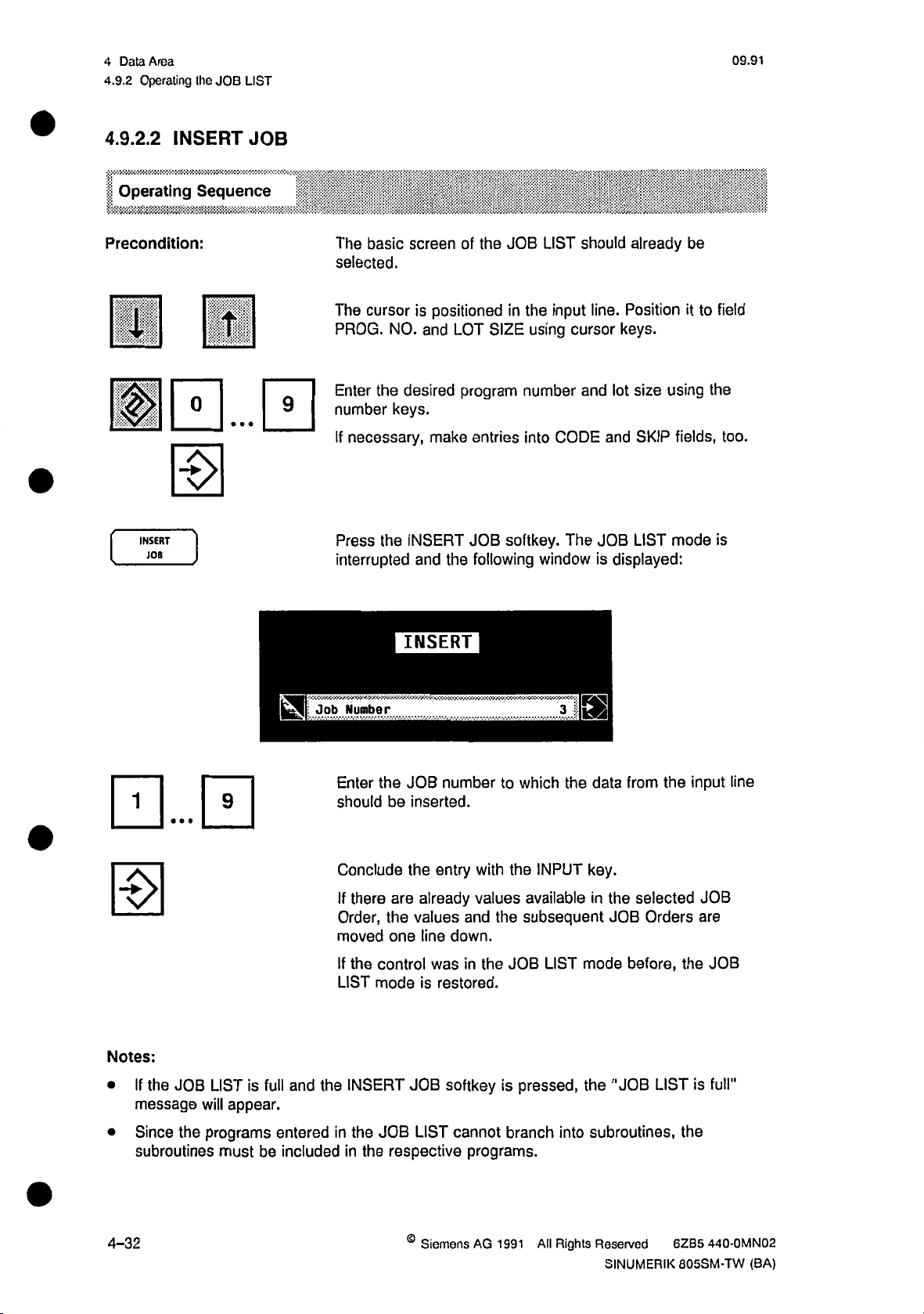
4
Data
4.9.2
Area
Operating
the
JOB
09.91
LIST
4.9.2.2
Operating
Precondition:
S
INSERT
Sequence
HI
[SHI
H
INSERT
JOB
JOB
The
basic
selected.
The
cursor
PROG.
Enter
number
If
Press
interrupted
NO.
desired
the
keys.
necessary,
the
screen
is
positioned
LOT
and
make
INSERT
the
and
JOB
of
the
in
SIZE
program
entries
softkey.
JOB
following
LIST
input
the
using
number
CODE
into
The
window
should
line.
cursor
and
and
JOB
is
already
Position
keys.
size
SKIP
LIST
using
mode
lot
displayed:
be
to
it
fields,
field
the
too.
is
m
Notes:
the
If
•
JOB
message
LISTisfull
will
appear.
HI
and
Job
Number
Enter
should
Conclude
If
there
Order,
moved
the
If
LIST
INSERT
the
INSERT
the
JOB
be
inserted.
the
are
the
one
control
mode
JOB
number
entry
already
values
line
down.
was
is
restored.
softkey
with
values
and
in
the
which
to
INPUT
the
available
subsequent
the
JOB
is
pressed,
3
the
LIST
m
data
key.
in
mode
the
from
the
JOB
before,
"JOB
the
selected
Orders
the
LIST
input
JOB
are
JOB
is
full"
line
Since
•
subroutines
4-32
programs
the
must
entered
be
included
in
in
the
the
JOB
LIST
respective
©
Siemens
cannot
programs.
AG
1991
branch
All
subroutines,
into
Rights
Reserved
SINUMERIK
the
440-0MN02
6ZB5
805SM-TW
(BA)
Page 93
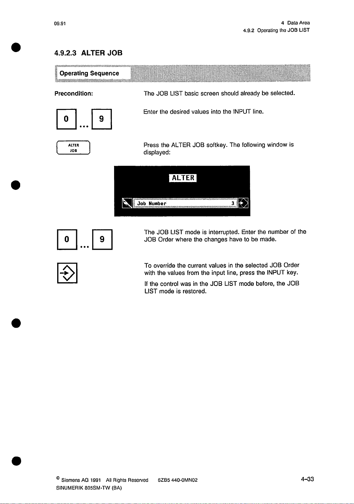
09.91
4.9.2
Operating
4
the
Data
JOB
Area
LIST
4.9.2.3
ALTER
Operating
Precondition:
ALTER
JOB
JOB
Sequence
HI
The
Enter
Press
displayed:
Number
Job
JOB
the
the
LIST
basic
desired
ALTER
ALTER
screen
values
JOB
should
into
the
softkey.
already
INPUT
The
3
E2
line.
following
selected.
be
window
is
The
JOB
To
with
If
the
LIST
LIST
JOB
Order
override
values
the
control
modeisrestored.
mode
where
the
current
from
was
the
in
the
is
changes
the
interrupted.
have
the
input
JOB
in
line,
LIST
values
Enter
be
to
selected
press
mode
number
the
made.
JOB
INPUT
the
before,
the
of
Order
key.
JOB
the
©
Siemens
SINUMERIK
AQ
1991
All
805SM-TW
Rights
(BA)
Reserved
6ZB5
440-0MN02
4-33
Page 94

Data
4
4.9.2
Area
Operating
the
JOB
09.91
LIST
4.9.2.4
Operating
Precondition:
CANCEL
CANCEL
JOB
JOB
Sequence
•••
m
9
The
JOB
the
JOB
Press
the
displayed:
Number
Enter
the
basic
LIST
LISTS
mode
CANCEL
CANCEL
number
JOB
of
screen
is
OFF.
softkey.
the
desired
should
The
3
IS
JOB
already
following
Order.
selected
be
window
and
is
H
0
0
To
cancel
orders
To
RECALL
one
exit
the
notch
cancel
key.
selected
press
up,
mode
without
JOB
Order
INPUT
the
changing
move
and
key.
anything,
all
the
press
following
the
4-34
©
Siemens
AG
1991
All
Rights
Reserved
SINUMERIK
440-0MN02
6ZB5
805SM-TW
(BA)
Page 95

09.91
4.9.2
Operating
4
the
Data
JOB
Area
LIST
4.9.2.5
APPEND
Operating
Precondition:
HE
APPEND
JOB
Sequence
JOB
JOB
The
the
JOB
Select
keys
and
using
"Code"
To
append
order
the
the
is
and
input
LIST
LIST
should
"Prog.
enter
number
"Skip"
the
in
basic
No."
the
keys.
job,
the
screen
be
not
and
desired
If
fields,
press
free
next
should
full.
Size"
"Lot
program
necessary,
too.
line
JOB
at
APPEND
already
fields
number
make
softkey.
the
top.
selected
be
using
and
lot
entries
the
into
The
and
cursor
size
the
new
Note:
The
is
0
program
to
used
with
stop
the
the
number
LIST
JOB
0
may
mode.
not
entered
be
in
the
JOB
LIST,
because
program
no.
©
Siemens
SINUMERIK
AG
1991
805SM-TW
All
Rights
(BA)
Reserved
6ZB5
440-0MN02
4-35
Page 96

4
4.9,2
Data
Operating
Area
the
JOB
09.91
LIST
4.9.2.6
Operating
|
Preconditions:
START
START
a
Sequence
The
•
•
•
•
When
ACTIVE"
program
"Ready"
automatically
To
status
The
JOB
The
AUTOMATIC
The
valid
you
press
is
in
line
the
start
the
field
displays
LIST
basic
JOB
Order
the
START
displayed.
"Current"
is
loaded
searched
program,
screen
mode
is
If
there
line,
and
for
press
"OFF".
should
has
been
present
softkey
an
is
next
the
checked.
the
next
NO
START
already
selected.
in
the
message
the
invalid
program
The
program
valid
key.
be
JOB
LIST.
program
from
LIST
JOB
selected.
LIST
"JOB
or
no
the
is
number.
AUTOMATIC
ACTIVE
Current
k'SSxA'**-
No.
No.
No.
No.
No.
No.
No.
No.
No.
Irj
1
2
3
4
5
6
7
8
9
:htcr:
mmm
SKP
PROGRAM
LIST
JOB
IPBSH*
1
If
II
7032
7002
7004
7006
0000
0000
0000
0000
0000
jjtil
:
i
1
......
22
15
15
i
2
5
1
1
1
1
1
ImS
mm
''IWob
IS
RUNNING
BEE
1
10
7
55
0
0 0
0
0
0
i||I
-
'
fei:
.....
1
7
III
2
21
8
31
0
0
0
0
.......
4-36
.....
......
.......
.....
*****
.ÿ*>«
.........
MI
.......
........
’’
......
.
.....
.
Mill,
H'9'M
.....
..
»»
.....
*************
®
Siemens
<.
.....
,?.M
mi,
AG
1991
innwaimj
.....
All
Rights
..........
,
MMM,..
m
M
......
Reserved
SINUMERIK
FSTOPI
fill
440-0MN02
6ZB5
805SM-TW
(BA)
Page 97

09.91
4.9.2
Operating
4
the
Data
JOB
Area
LIST
remaining
The
the
program
If
automatically.
Note:
If
the
AUTOMATIC
4.9.2.7
Operating
Preconditions:
STOP
STOP
number
number
The
JOB
of
"0000"
LISTS
modeisswitched
Sequence
program
is
hastobe
repetitions
displayed
then
off,
the
JOB
The
•
displayed
The
•
The
•
stop
the
To
softkey.
completed
displayed
is
"Current"
der
in
restarted
LISTS
JOB
LISTS
LIST
JOB
AUTOMATIC
JOB
program
The
(until
the
in
basic
LISTS
M02/M30).
mode
status
"Remain"
in
line,
manually.
is
mode
should
field.
screen
should
mode
mode
progress
in
JOB
the
stopped
be
should
any
at
will
field.
LISTS
automatically.
si?®
active,
already
already
time,
press
continue
mode
"ACTIVE"
selected.
be
be
selected.
the
until
stops
is
STOP
Note:
If
the
AUTOMATIC
4.
9.2.
8
NEXT
Operating
Preconditions:
(
NEXT
JOB
I
mode
JOB
Sequence
is
switched
off,
The
•
The
•
The
•
"Ready"
The
•
field).
To
start
Order
press
next
the
JOB
the
LIST
JOB
AUTOMATIC
JOB
next
line.
LISTS
JOB
the
next
regardless
NEXT
the
JOB
Order.
LISTS
basic
Order
mode
JOB
of
the
JOB
mode
screen
mode
should
is
Order
number
softkey.
stopped
is
should
should
already
stopped
cancel
and
of
The
automatically.
already
be
active.
be
("OFF"
the
still
parts
LIST
JOB
be
loaded
the
in
actual
be
to
proceeds
selected.
into
status
JOB
made,
with
©
Siemens
SINUMERIK
AG
1991
805SM-TW
All
Rights
(BA)
Reserved
6ZB5
440-0MN02
4-37
Page 98

4
Data
4.9.2
Area
Operating
the
JOB
09.91
LIST
4.9.2.9
Operating
Preconditions:
DELETE
JOB
DELETE
Sequence
JOB
LIST
The
The
field).
you
appears:
JOB
JOB
•
•
When
window
DELETE
Return
Confirm
LIST
LISTS
press
JOB
basic
mode
the
DELETE
LIST
0
53
screen
stopped
is
JOB
?
should
("OFF"
softkey,
already
in
the
be
selected.
status
the
following
0
0
To
delete
To
exit
RECALL
the
the
delete
key.
entire
mode
JOB
LIST,
without
press
deleting
the
INPUT
anything,
key.
press
the
4-38
Siemens
AG
1991
All
Rights
Reserved
SINUMERIK
440-0MN02
6ZB5
805SM-TW
(BA)
Page 99

06.92
4.9.3
4
Correcting
Area
Data
Mistakes
4.9.3
Note:
message
The
message
Message
7000
7001
7002
7003
Correcting
numbers
numbers.
Please
Cause
message
The
LIST
is
The
selected
when
JOB
LIST.
JOB
JOB
LIST
been
started.
LIST
JOB
to
load
EXTERNAL
Mistakes
are
standard
observe
is
active.
function
LIST
without
is
full
orders
by
mass
values.
the
flashing
is
is
OFF,
JOB
and
it
HAND
storage
machine
when
only
e.g.
Orders
attempted
was
from
or
device.
machine
The
manufacturer’s
JOB
possible
DELETE
has
manufacturer
instructions.
Remedy
Stop
•
softkey.
Repeat
•
Enter
•
from
device
Cancel
•
DELETE
JOB
softkey
may
LIST
JOB
the
function.
the
by
orders
HAND
EXTERNAL
disk
(e.g.
orders
with
or
]
different
use
withj
mass
drive).
DELETE
JOB
STOP
k,
load
or
storage
LIST
J
7004
7005
7006
7007
7008
7009
Ananother
while
DELETE
Invalid
An
Size",
processed.
Softkey
not
Selected
either
memory.
line
order
with
"Code",
in
AUTOMATIC
program
in
pp
function
JOB
number
invalid
or
START
memory
performed
was
LIST
in
selected.
"Prog.
"Skip"
pressed
|
mode.
available
is
not
in
or
progress.
No.",
was
while
external
"Lot
•
•
•
•
•
•
•
•
Wait
until
function
Check
(valid
Check
Progr.
Lot
line
no.
No.:
Size
Code
Skip
Select
Select
Check
external
Check
Siemens
Call
check.
DELETE
completed.
is
JOB
number
9).
1
to
for
:
:
:
the
1
to
1
to
0
to
0
to
program.
and
Service
999
999
999
9999
available
connectors.
order
AUTOMATIC
available
program
if
memory.
cable
LIST
following:
(BCD)
(Binary)
(Binary)
(Binary)
mode.
in
hardware
for
®
Siemens
SINUMERIK
AG
1991
All
805SM-TW
Rights
(BA)
Reserved
6ZB5
440-0MN02
4-39
Page 100

4
Data
4.9.3
Area
Correcting
09.91
Mistakes
Message
7010
7011
7012
7013
Cause
Selected
in
either
memory.
Error
at
Error
at
LIST
JOB
load
to
storage
program
memory
pp
program
deleting
is
full
orders
device.
is
loading.
a
program
and
from
EXTERNAL
available
not
in
or
was
it
external
via
FB62.
attempted
mass
Remedy
Load
•
external
Select
•
Check
•
interfaces.
Check
•
Delete
•
DELETE
softkey
program
mass
other
peripheral
FB62
orders
JOB
memory
pp
into
storage
program
device.
number.
device
and
programming.
with
or
DELETE
JOB
L
LIST
or
J
4-40
©
Siemens
AG
1991
All
Rights
Reserved
SINUMERIK
440-0MN02
6ZB5
805SM-TW
(BA)
 Loading...