

Page 1
Page 2
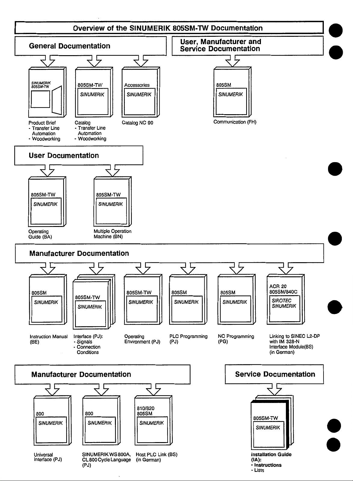
Overview
of
the
SINUMERIK
805SM-TW
Documentation
General
39
SINUMERIK
805SM-TN
Brief
Product
Transfer
Automation
Woodworking
-
User
Line
Documentation
39.
805SM-TW
SINUMERIK
Documentation
39
805SM-TW
SINUMERIK
Catalog
Transfer
-
Automation
Woodworking
-
Line
805SM-TW
SINUMERIK
39
39
Accessories
SINUMERIK
NC
Catalog
90
User,
Service
Manufacturer
Documentation
39
805SM
SINUMERIK
Communication
and
(FH)
Operating
(BA)
Guide
Manufacturer
39
805SM
SINUMERIK
Instruction
(BE)
Manual
Manufacturer
39
Multiple
Operation
Machine
(BN)
Documentation
39
805SM-TW
SINUMERIK
Interface
-
(PJ):
Signals
Connection
Conditions
Documentation
39
39
805SM-TW
SINUMERIK
Operating
Environment
(PJ)
39 39
805SM
SINUMERIK SINUMERIK
PLC
Programming
(PJ)
805SM
NC
Programming
(PG)
Service
39
ACR
20
805SM/840C
SIROTEC
SINUMERIK
Linking
to
IM
with
Interface
German)
(in
328-N
L2-DP
SINEC
Module(BS)
Documentation
39
800
SINUMERIK
Universal
Interface
(PJ)
800
SINUMERIK
SINUMERIK
Cycle
CL
800
(PJ)
WS800A,
Language
810/820
805SM
SINUMERIK
Link
PLC
Host
German)
(in
(BS)
805SM-TW
SINUMERIK
Installation
(IA):
•
Instructions
Lists
-
Guide
Page 3

SINUMERIK
805SM-TW
Software
Version
Installation
Installation
Service
Guide
Documentation
4
Instructions
Valid
for:
Control
SINUMERIK
Edition
02.94
805SM-TW
Software
Version
3
and
4
Page 4
SINUMERIK®
documentation
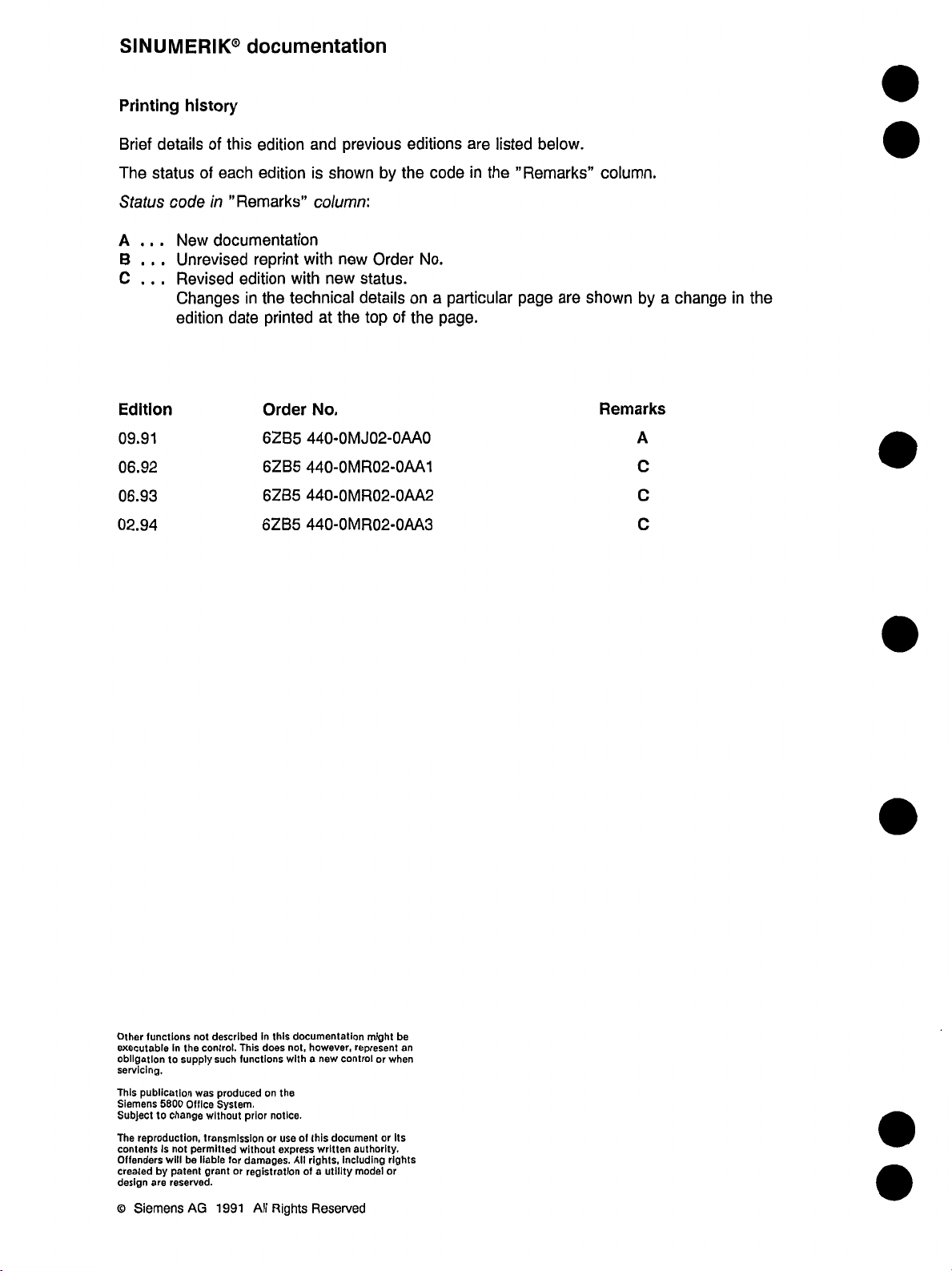
Printing
detailsofthis
Brief
The
status
Status
A
...
B
.
.
.
C
.
.
.
Edition
09.91
06.92
06.93
02.94
history
each
of
’’Remarks”
in
code
documentation
New
Unrevised
Revised
Changes
edition
date
edition
edition
reprint
edition
the
in
printed
Order
6ZB5
6ZB5
6ZB5
6ZB5
previous
and
new
the
by
:
Order
status.
details
of
top
is
shown
column
with
new
with
technical
at
No.
440-0MJ02-0AA0
440-0MR02-0AA1
440-0MR02-0AA2
440-0MR02-0AA3
editions
the
code
No.
a
on
page.
the
listed
are
in
the
particular
below.
’’Remarks”
page
are
column.
shown
Remarks
by
A
C
C
C
a
change
in
the
functions
Other
executable
gatlon
obll
servicing.
publication
This
Siemens
Subject
to
The
reproduction,
contents
Offenders
by
created
design
are
©
Siemens
in
to
5800
change
Is
not
will
patent
reserved.
not
control.
the
supply
was
Office
transmission
permitted
be
liable
grant
AG
described
such
produced
System.
without
for
or
1991
In
this
This
does
functions
on
notice.
prior
or
without
damages.
registration
Rights
All
documentation
not,
however,
a
new
with
the
of
this
use
express
written
rights,
All
utility
a
of
Reserved
might
represent
controlorwhen
documentorIts
authority.
including
rights
model
or
be
an
Page 5
Preliminary
Remarks
Notes
SINUMERIK
The
General
•
User
•
Manufacturer
•
Service
•
Service
The
Installation
•
Installation
•
present
The
setting
The
More
Siemens
data
supply
information
the
for
documentation
documentation
documentation
documentation
Installation
that
options
of
local
Technical
Reader
805SM-TW
documentation
Instructions
Lists
Guide
be
must
is
other
on
or
national
Notes
fj;
documentation
comprises
specifies
parameterized.
included.
not
SINUMERIK
office.
organized
is
following
the
the
method
805SM-TW
four
in
publications:
of
installation
publications
parts:
and
are
obtainable
explains
all
machine
from
and
your
INTERFACE
•
the
of
4
DESCRIPTION
modules
and
jumper
Very
PART
assignments.
important
by
this
Cables
2:
information
form
presentation.
of
and
will
Hardware
be
emphasized
contains
detailed
a
overview
4
Page 6
Notes
on
safety
requirements
When
under
operating
dangerous
electric
voltage.
WARNING
devices,
some
machine
parts
inevitably
are
A
h
Trained
personnel
A
$
Unqualified
result
accordingly
mounting,
device/system.
Trained
instruction
following
Personnel
•
and
regulations.
Personnel
•
regulations
safety
operation
in
serious
trained
installation
personnel
manuals
qualifications:
typify
devices.
non-observanceof
or
the
damages
personnel
and
according
or
trained,
circuits
trainedorinstructed
in
the
and
fields
human
to
well
operation
WARNING
the
product
the
in
instructed
devices
servicing,
of
warning
machines.
beings
aquainted
shouldbeallowed
safety
authorizedtoswitch
or
according
according
or
regulations
labels)
have,
operating
with
to
to
the
the
may
signs
Only
configuration,
to
operate
(included
for
example,
relevant
relevant
and
in
on/off,
safety
safety
repairing
the
the
the
earth
m
•
•
Make
the
with
mounting,
Personnel
modules
or
Personnel
well
and
Guides.
sure
that
relevant
starting-up
instructed
risk
at
personnel
and
or
from
for
with
operation
electrostatic
the
trained
instructed
aquainted
the
documentations
operation
the
Operating
is
well
regarding
the
for
charges.
aquainted
the
of
operation
automation
of
and/or
installation,
Programming
control.
of
components
techonology
Page 7
Notes
The
hand,
machines.
Notes
servicing
below.
on
on
following
they
on
The
products
the
safety
personnel
A
dangers
notes
may
prevent
regulations
signals
themselves:
serve,
damages
or
have
This
warning
harm
safety
on
the
damages
and
following
the
signal
notes
serious
or
precautions
hand,
one
the
to
warnings
machine
the
to
meanings
signifies
on
damage
for
product
to
prevent
in
the
products
the
have
the
personal
described
damages
itself
are
the
sense
in
DANGER
sense
themselves
the
machine
to
been
not
WARNING
safety
or
connected
life
to
represented
this
of
documentation
the
of
that
will
taken.
user,
signals
and
grievous
the
if
on
and
specified
the
of
devices
and
healthofthe
the
by
documentation
death,
occur
other
the
user
defined
and
the
bodily
or
notes
A
A
m
signal
This
warning
harm
or
safety
precautions
signal
This
warning
damage
have
not
Notes
signifies
notes
serious
signifies
notes
the
to
been
comprise
in
on
the
products
damage
have
in
products
the
on
machine
taken.
important
the
the
may
sense
to
not
sense
the
of
themselves
machine
the
been
taken.
CAUTION
the
of
themselves
occur
the
if
information
documentation
death,
that
may
occur
documentation
that
specified
minor
safety
the
if
bodily
m
and
the
grievous
specified
and
the
harm
precautions
bodily
or
about
the
of
product
the
documentation
or
the
worth
relevant
noticing.
part
Page 8
Use
for
the
actual
purpose
•
•
Active
•
•
catalogue
the
devices
The
product
accordance
descriptions
safety
human
or
Depending
can
faults
example,
messages,
with
message.
This
differentiation
dangerous
supplied.
device/system
The
A
or
in
and
components
described
the
with
of
configuration,
regulations,
beings
passive
under
faults
on
the
dangerous.
be
they
as
undangerous
and
however,
or
system
technical
the
recommended
has
relevant
product
the
normal
an
of
purpose
Active
lead
an
to
may
the
possible
of
Additional
be
generated
dangerous
harm.
bodily
operational
dent
limit
components
description
developed,
been
regulations.
safety
installation,
represents
conditions.
automation
electronic
an
of
faults
illegal
switching
prevent
faults
is
faults
external
in
connection
causing
faults
These
status
switches,
are
to
and
admitted
or
manufactured,
proper
danger
no
device
automation
generally
are
on
of
output
the
and
their
essential
for
WARNING
precautions
with
serious
precautions
in
even
mechanical
case
applied
be
only
in
by
When
operation
with
dangerous
the
a
of
purpose-dependent
safety
all
havetobe
the
damages
must
errors
of
disables
only
connection
Siemens.
tested
adhering
servicing
and
regard
device,
drive.
dangerous
automation
activeaswell
for
Passive
regulations
taken
to
guarantee
(e.g.
etc.).
for
and
to
to
drive
operational
the
by
use
the
with
non-Siemens
documented
corresponding
the
and
machine
controls,
faults
in
division
the
of
or
conditions
device
or
to
machine
enforce
means
of
specified
in
specified
the
or
parts
passive
as
for
connection
status
into
product
have
prevent
or
even
safe
a
indepen¬
in
to
h
Page 9
Notes
Since
the
on
the
undangerous
product
products
product
configuration
are
mostly
parts
integration
of
into
larger
the
systems
Please
unit.
or
units,
note
these
the
notes
following
are
facts
guideline
a
particular:
in
for
7
Further
If
instructions
ations
notes
measuringortesting
for
the
active-part
for
A
h
is
It
inevitable
even
by
Improper
is
prevention
working).
to
high
a
if
configuring
when
means
operation
to
or
generate
required
accidents
of
Use
Devices
Siemens
exchanging
When
quoted
improper
as
well
Always
opening
Only
use
Do
not
danger
recharge
or
exchanging!
when
Dispose
using
When
Improper
installation
increased
the
relevant
operated.
strictly
degree
several
of
prevent
other
the
for
the
proper
supplied
service
inthe
list
servicing
serious
pull
the
device.
the
specified
the
expose
explosion
of
lithium
battery
of
screens:
operation,
of
radiation
safety
observe
of
safety
an
channels,
may
dangerous
sources
active
VBG
electric
by
or
machine
of
spare
may
damage
mains
batteries
(maximum
or
cells
especially
another
of
regulations
instruction
the
has
automation
for
inactivate
faults
of
device,
4.0,
adhere
especially
tools.
WARNING
Siemens
by
plug
types
mercury
type
X-rays.
may
services
parts
parts.
cause
the
to
initiate
or
when
fire
to
storage
or
picture
of
These
manuals
been
reached
device
example.
measures
danger.
to
the
Section
only
be
authorized
components,
or
Unauthorized
death
machine.
or
temperature
batteries,
changes
and
grievous
or
disconnector
the
exchanging
solder
on
use
batteries
in
the
may
tube
changes
the
device
regulations
(Permissible
8
reparied
the
100
the
as
by
by
Siemens.
only
opening
bodily
fuses.
cells
for
°C).
same
hazardous
high
voltage
lead
to
not
do
must
not
and
the
parts
use
and
harm
before
the
Do
not
types
waste.
or
an
comply
be
devi¬
as
open
the
with
Page 10
Preconditions
and
Visual
Control
0
Installation
Module
Voltage
Standard
Service
Data
Overview
and
Installation
Displays
Checklist
Validity
0
0
Check
m
0
0
0
Machine
NC
PLC
Data
Functional
Monitoring
Description
Saving
Data
Programmer
with
Description
0
9
(PG)
0
0
0
Page 11
Contents
Page
1
1.1
1.2
1.3
1.3.1
1.3.2
1.3.3
1.3.4
1.3.5
.3.6
1
.3.7
1
1.3.8
1.3.9
2
3
3.1
3.1.1
3.1
.2
Preconditions
Preconditions
Preliminary
Visual
remarks
system
Stickers
Earthing
Position
Cable
encoders
laying
Shielding
Operator
Summary
Central
panel
status
controller
Cables
Installation
Module
Overview
Central
Central
Checklist
Overview
SINUMERIK
controller
controller
Visual
and
installation
of
....
and
battery
(with
(with
....
screen
check
Check
.
805SM-TW
subassembly)
V
24
subassembly)
V
230
1-1
1-1
1-1
1-3
1-3
1-4
1-4
1-4
1-4
1-4
1-5
1-5
1-5
2-1
3-1
3-1
3-2
3-3
4
4.1
4.1.1
4.1.2
4.2
4.3
4.3.1
4.3.2
4.3.3
4.4
5
5.1
5.2
5.2.1
5.2.2
5.2.3
5.2.4
5.2.5
5.2.6
5.2.7
Voltage
Voltage
Voltage
Battery
Starting
Validity
CPU
EPROM
Validity
and
check
supply
buffering
sequence
check
monitoring
check
checkofcentral
Software
Standard
Standard
installation
Axis
Checking
Position
control
Maximum
Definition
Variable
Closing
Axis
incremental
the
traverses
Validity
of
RAM
of
the
identification
Installation
installation
and
of
adjusting
resolution,
axis
speed
maximum
of
weighting
position
in
control
JOG
Check
memory
control,
opening
screen
controller-monitor-operator
and
NC
the
PLC
control
input
directionofthe
resolution
setpoint
loop
mode
keyboard
axes
feed
4-1
4-1
4-1
4-2
4-3
4-3
4-3
4-3
4-4
4-5
5-1
5-1
5-4
5-4
5-5
5-6
5-6
5-6
5-7
5-7
Page 12
5.2.8
5.2.9
5.2.10
5.2.11
5.2.11.1
5.2.11.2
5.2.12
5.2.13
5.2.14
5.3
5.3.1
5.3.2
5.3.3
5.3.4
5.3.5
5.4
5.4.1
5.4.2
5.4.3
5.4.4
5.4.5
5.4.6
5.5
5.6
Multgain
Servo
NC
gain
Kv
Acceleration
Reference
Reference
Reference
MD
NC
MD
NC
Contour
Spindle
point
point
point
204*
212*
monitoring
installation
Preconditions
Speed
inputs
Acceleration
Spindle
Testing
Installation
Selection
Input
Setting
Definition
Selection
Tool
User
Memory
setting
spindle
of
of
aggregate
of
vertical
of
of
of
carrier
Memory
allocation
machine
the
spindle
configuration
260*
MD
factor
approach
approach
approach
and
NC
MD
(clamping
gears
for
time
constants
data
in
MDA
the
tool
carrier
coordinate
offsets
drilling
visualization
designations
Submodule
without
automatic
with
(exact
208*
tolerance)
mode
spindles
display
(UMS)
automatic
stop
system
direction
direction
coarse
limit
determination
determination
fine)
and
5-8
5-10
5-12
5-14
.
..
5-14
5-17
5-18
5-18
5-19
5-20
5-20
5-22
5-22
5-22
5-22
5-24
5-24
5-26
5-27
5-28
5-30
5-32
5-34
5-35
6
6.1
6.2
6.3
7
7.1
7.2
7.3
7.3.1
7.3.2
7.3.3
7.3.4
7.3.5
7.3.6
7.3.7
7.3.8
7.3.9
7.4
7.5
7.6
Service
Selection
Service
Service
Data
General
R
Setting
Working
Spindle
Dry
Displays
of
data
data
notes
parameters
data
area
data
run
feedrate
service
for
for
(SD)
limitations
Spindle-specific
data
data
data
data
data
for
for
for
for
bits
data
data
data
Setting
Setting
Setting
Setting
Setting
machine
NC
machine
NC
machine
PLC
displays
for
axes
spindles
and
incremental
values
offset
technology
user
the
drilling
files
modules
communication
(NC
values
(NC
bits
values
MD
MD
(PLC
and
axes
dimension
values)
bits)
MD)
spindle
.
6-1
6-1
6-2
6-3
7-1
7-1
7-1
7-2
7-2
7-2
7-4
7-4
7-5
7-6
7-6
7-8
7-8
7-12
7-12
7-12
Page 13
8
NC
Machine
Data
8—1
8.1
8.1.1
8.1.
1.1
1.2
8.1.
8.1.2
8.1.3
8.1.4
8.2
8.2.1
8.2.2
8.2.3
8.2.4
8.2.5
8.2.6
8.2.6.1
6.
8.
2.
6.3
8.2.
8.2.6.4
8.2.7
8.2.8
8.2.9
8.3
8.3.1
8.3.2
8.3.3
8.3.4
8.3.5
8.3.6
General
Overview
Overview
Overview
Display
Effectiveness
Input
units
Description
General
Axis-specific
Spindle-specific
Machine
Machine
Machine
General
2
Machine
Machine
Machine
Machine
Machine
Machine
Description
General
Spindle-specific
Channel-specific
Axis-specific
Bits
for
Bits
for
notes
of
NC
MDs
NC
of
MD
of
MD
NC
input
and
individual
of
NC
of
MD
NC
values
MD
NC
NC
data
data
data
notes
data
data
data
data
data
data
NC
aggregates
for
spindles
for
graphical
for
explanation
explanation
explanation
for
polymarkers
for
colour
for
NC
of
MD
bits
NC
NC
NC
MD
leadscrew
tool
carrier
values
bits
MDs
NC
of
machine
values
MD
values
values
MD
elements
graphical
for
graphical
for
graphical
for
visualization
attributes
MD
bits
MD
bits
bits
MD
bits
compensation
error
and
spindle
data
displays
graphics
element
element
element
line
rectangle
circle
.
8-1
8-1
8-1
8-2
8-3
8-3
8-3
8-4
8-4
8-21
8-54
8-64
8-65
8-68
8-68
8-69
8-72
,
.
8-75
8-78
8-80
8-81
8-82
8-82
8-103
8-105
8-109
8-114
8-114
9
9.1
9.2
9.2.1
9.2.2
9.3
9.3.1
9.3.2
9.3.3
9.3.4
9.4
9.5
10
10.1
10.2
10.2.1
10.2.2
10.2.3
10.2.4
10.3
PLC
Description
Technical
PLC
Overview
data
machine
of
Description
PLC
installation
General
NC
PLC
PG
PLC
PLC
Data
General
Diskette
Formatting
Copying
Changing
Listing
Data
notes
machine
«ÿ>
PG
commands
operating
status
Saving
notes
handling
diskettes
diskettes
directories
handling
(PLC
data
MDs
PLC
of
PLC
data
for
link
system
Programmer
with
diskettes
MDs
the
(BESY)
MDs)
....
..
.
PLC
(PG)
9-1
9-1
9-2
9-2
9-2
9-15
9-15
9-15
9-16
9-16
9-17
9-18
10-1
10-1
10-1
10-1
10-3
10-4
10-5
10-6
Page 14
10.3.1
10.3.2
10.4
10.4.1
10.4.2
10.4.3
10.4.4
10.4.5
10.5
10.6
Listing
Copying
NC
<->
files
files
PG
Cable
Interface
Interface
Additional
initial
Data
Procedure
Procedure
data
transfer
parameters
parameters
baud
rates
identifiers
data
for
data
for
transfer
on
the
on
the
(for
transfer
SINUMERIK
PG
PG
from
from
635,
PG
the
the
805SM
PG
675,
685
SINUMERIK
SINUMERIK
the
to
PG
only)
805SM
the
to
805SM
PG
10-7
10-7
10-8
10-8
10-8
10-9
10-9
10-10
10-10
..
10-12
.
11
11.1
11.2
11.2.1
11.2.2
11.2.3
11.2.4
11.3
11.3.1
11.3.2
11.4
11.4.1
11.4.2
11.4.3
11.4.4
11.4.5
11.4.6
11.5
11.5.1
11.5.2
11.5.3
11.5.4
11.6
11.6.1
11.6.2
11.6.3
11.6.4
11.6.5
11.7
11.7.1
11.7.2
11.8
11.9
11.9.1
11.9.2
11.9.3
11.9.3.1
11.9.3.2
11.9.3.3
11.9.4
11.10
Functional
Leadscrew
Spindle
Corresponding
analog
S
9,
M1
Influence
Rotary
Corresponding
Functional
Link
to
General
System
Jumper
Function
Illustrationofthe
Description
error
control
M4,
(M3,
Oriented
the
of
function
axis
description
PLC
host
notes
configuration
assignments
blocks
compensation
MDs
M5)
spindle
on
PLC
data
and
error
monitoring
Example
Synchronism
General
Reference
Activating/deactivating
Interface
notes
point
signals
approach
and
machine
Joblist
Functional
Preconditions
Procedure
Messages
Trouble
Tapping
description
of
joblist
of
shooting
dynamic
with
joblist
installation
Description
Machine
Actual
Connecting
value
General
System
SINUMERIK
Basic
program
Interface
Compatibility,
Procedure
Spline
interpolation
description
data
measurement
an
external
notes
configuration,
805SM-TW
for
external
signals,
machine
performance
external
of
stop
the
spindle
of
link
messages
with
the
function
modules
principle
synchronous
data
installation
following
with
error
absolute
PLC
assignments
external
with
PLC
data
characteristics,
installation
PLC
axes
compensation
encoder
PLC
synchronization
11-1
11-1
11-10
11-10
11-10
11-11
11-18
11-19
11-19
11-19
11-22
11-22
11-22
11-23
11-27
11-28
11-29
11-31
11-31
11-33
11-35
11-36
11-37
11-37
11-37
11-38
11-38
11-40
11-41
11-41
11-42
11-46
11-48
11-48
11-49
11-50
11-50
11-52
11-52
11-53
11-54
Page 15
11.11
11.11.1
11.11.2
11.11.3
11.12
11.13
11.13.1
11.13.2
11.13.3
11.14
11.14.1
11.14.2
11.14.3
11.14.4
11.15
11.16
Operation
General
without
notes
Start-up
Programming
Gauging
Operation
General
Functional
Control
NC
General
Functional
PC
on
without
notes
description
restart-up
operation
notes
preconditions
connection
Operation
PTP
software
Precontrol
the
via
for
NC
fly
VGA
PC
MS-DOS
....
...
PC
11-54
11-54
11-55
11-55
11-56
11-58
11-58
11-59
11-61
11-63
11-63
11-64
11-65
11-66
11-67
11-69
12
12.1
12.2
12.3
12.4
Monitoring
General
Alarm
Display
List
notes
numbers
of
alarms
of
and
alarms
groups/clearing
and
messages
alarms
12-1
12-1
12-1
12-3
12-4
Page 16

06.92
1
Preconditions
and
Visual
Check
1
1.1
a)
b)
c)
d)
e)
Preconditions
Preconditions
The
electrical
prepared
axes
The
customer
measuring
The
If
customer
the
especially
The
cables
the
control
Flexible
•
•
Support
unit,
earth
bar
earth
barinmachine
earth
must
machine,
Recommendation:
the
Limit
switches)
travel
for
and
for
PLC
systems
has
specified
the
to
neutral
wires
SINUMERIK
in
be
provided
machine
ranges
greater
installation
of
mechanical
operation
program
installed
screening.
machine
point
installed
(confirmedbycustomer).
must
must
adapter
must
according
column
by
operation
by
transferring
clearance
and
configuration
operational
be
be
installed
plugs,
be
connected.
the
to
(visual
805SM
the
check):
interface
interface
customer’s
and
the
cam
distances.
Visual
the
of
and
wired
and
check
The
Interface
unit:
unit:
personnel
customer
switches
limit
Check
machine
correct
cable
Description.
PLC
must
have
must
control
the
to
installation,
shields
10
mm2
10
mm2
dealing
when
program.
(EMERGENCY
complete
be
been
(visual
must
pretested
check).
tension
connected
be
with
the
STOP
and
the
possible.
if
and
relief
interface
limit
to
f)
g)
1.2
Synthetic
charges
regarding
previously
Modules
necessary
The
Test
tapes
Preliminary
or
of
high-voltage
and
rubber
several
discharging
power
disconnected.
Even
circuiting
RAM
control
the
if
across
memories
machine
availabletocheck
be
must
remarks
soles
and
kilovoltsinhuman
discharges.
yourself
supply
is
the
may
cables
disconnected,
RAM
V<x
be
corrupted
must
data
especially
Therefore,
on
an
can
it
printed
or
be
available.
machine-specific
the
synthetic
beings.
Integrated
never
earthed
only
hastobe
part
be
conductors.
printed
conductors
rubber
or
touch
the
of
pulled
or
reckoned
Otherwise,
functions.
flooring
circuits
have
conductors
system.
inserted
static
with
data
may
even
may
when
load
buffered
burn
produce
a
great
and
components
control
the
to
out.
static
sensitivity
is
prevent
CMOS
in
the
without
short-
©Siemens
SINUMERIK
AG
All
1991
805SM-TW
Rights
(IA)
Reserved
6ZB5
440-0MR02
1-1
Page 17
Preconditions
1
and
Visual
Check
09.91
MOS
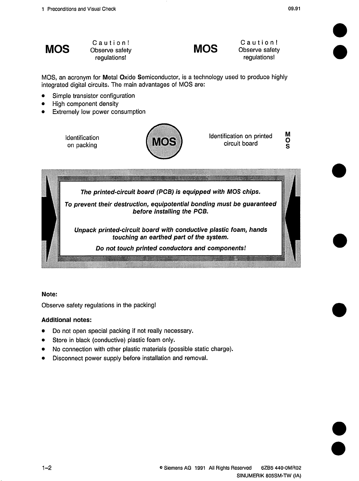
MOS,
an
integrated
Simple
•
High
•
Extremely
•
Identification
To
Caution!
Observe
acronym
digital
transistor
component
on
for
circuits.
power
low
packing
.
The
printed-circuit
prevent
safety
regulations!
Metal
Oxide
main
The
configuration
density
consumption
their
destruction,
Semiconductor,
advantages
MOS
board
before
(PCB)
equipotential
installing
of
MOS
is
MOS
technology
a
is
are:
equipped
bonding
PCB.
the
Caution!
Observe
used
to
Identification
circuit
MOS
with
be
must
safety
regulations!
produce
on
printed
board
chips.
guaranteed
highly
M
s
I
P
Note:
Observe
Additional
•
•
•
•
Unpack
safety
notes:
Do
not
open
in
Store
No
Disconnect
black
connection
printed-circuit
not
Do
regulations
special
power
packing
(conductive)
other
with
supply
touching
touch
in
the
plastic
plastic
before
board
an
earthed
printed
packing!
really
if
not
foam
materials
installation
conductive
with
part
conductors
necessary.
only.
(possible
and
the
of
and
static
removal.
plastic
system.
components!
charge).
foam,
hands
1-2
®
Siemens
AG
1991
All
Rights
Reserved
SINUMERIK
6ZB5
440-0MR02
805SM-TW
(IA)
Page 18
09.91
Preconditions
1
and
Visual
Check
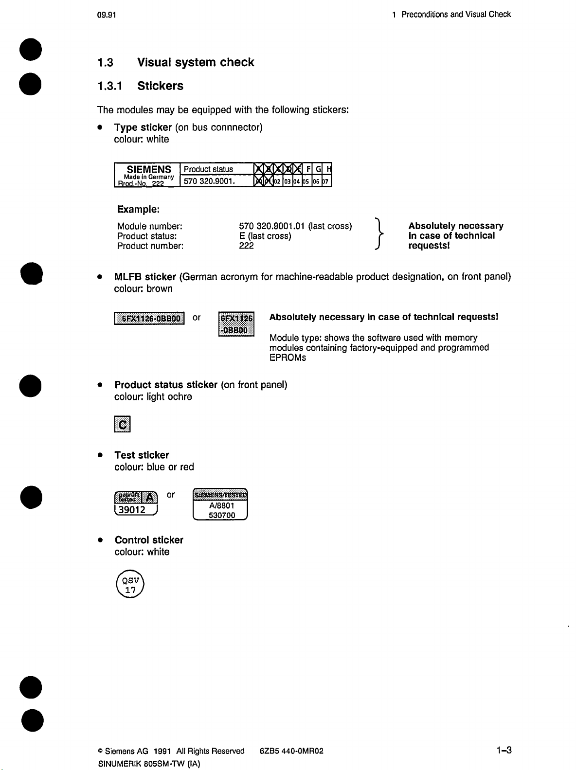
1.3
1.3.1
The
Type
•
colour:
MLFB
•
colour:
|
Visual
system
Stickers
modules
SIEMENS
Ma
Rrnri
Example:
Module
Product
Product
I-6FX1
may
be
sticker
(on
white
Product
ld.N0nG2e22any
number:
status:
number:
sticker
570
(German
brown
1
26-0BB00
|
check
equipped
connnector)
bus
status
320.9001.
acronym
or
[|§$|||||
•QBBQO
following
the
with
IBQI3BI
X
X
IS331B381
320.9001.01
570
cross)
(last
E
222
for
Absolutely
Module
modules
EPROMs
stickers:
FGF
37
05
06
(last
cross)
machine-readable
necessary
shows
type:
containing
the
factory-equipped
}
product
case
In
software
Absolutely
case
In
requests!
designation,
technical
of
used
with
programmed
and
necessary
technical
of
on
front
requests!
memory
panel)
•
•
mm
•
Product
colour:
sticker
Test
colour:
[39012
Control
colour:
/QSV\
status
light
blue
J
sticker
white
ochre
red
or
°r
sticker
(on
front
StEMENS'TESTEO
A/8801
530700
panel)
®
Siemens
SINUMERIK
AG
All
1991
805SM-TW
Rights
(IA)
Reserved
62B5
440-0MR02
1-3
Page 19

Preconditions
1
and
Visual
Check
06.92
•
colour:
1.3.2
For
trouble-free
black/yellow
Earthing
mark
EGB
disturbances.
(see
section
1.3.3
Special
etc.)
gap
and
Adjustment).
Instruction
Position
emphasis
and
(German
Disconnect
Components
operation,
sure
Make
encoders
has
to
measuring
rotary
acronym
faultless
earth
that
Manual
be
put
for
power
conductors
and
the
on
systems
components
supply
risk
at
earthing
Interface
proper
(coupling
risk
at
before
is
installation
from
electrostatic
absolutely
are
not
Description
installation
etc.)
from
necessary
kinked
Part
the
of
(see
Heidenhain’s
electrostatic
removal.
or
discharges
lead
to
have
and
2
-
linear
the
Cables
measuring
discharges)
external
off
required
Hardware).
and
systems
Guide
to
(EGB)
cross
(air
Installation
Check
may
not
correct
lead
liable.
1.3.4
Isolate
improper
Smooth
Check
Smooth
power
for
1.3.5
External
via
the
connectors
1.3.6
Check
that
wiring
problems
to
Cable
cables
earthing,
running
running?
(optical-fibre
kinks
at
Shielding
shields
of
Operator
the
keys,
tight
and
far
as
laying
control
from
may
they
minimum
Contouring
all
cables
INTERFACE
(see
panel
lights,
positioning
accuracy
as
cables
generate
speeds
cables).
error?
running
and
symbols
of
connectors.
and
surface
as
far
as
voltages
ripple
longer
no
is
to
or
from
the
DESCRIPTION
screen
and
screen
are
quality
possible.
affecting
possible.
control
PART
O.K.
Measuring
are
concerned
Avoid
the
have
to
2
CABLES
-
systems
earth
speed
be
earthed
of
for
because,
loops
controller
at
HARDWARE).
AND
other
which
set
the
products
are
we
like
value.
control
1-4
®
Siemens
AG
1991
All
Rights
Reserved
SINUMERIK
6ZB5
440-0MR02
805SM-TW
(IA)
Page 20
06.92
1
Preconditions
and
Visual
Check
1.3.7
Make
screwed
Packing
Make
(Parts
Check
Summary
that
sure
the
to
directions:
that
sure
list
attatched
all
socket
ones.
Check
1.3.8
The
off
1.3.9
Check
HARDWARE,
conductor
The
guidelines
jumper
Central
write-read
(see
chapter
Cables
all
cables
is
respective
and
status
modules
the
devices,
log-book
the
to
ICs
for
assignments
controller
memory
BATTERY
according
especially
necessary!
department
sales
remedial
and
check
(RAM)
complete
and
original
proper
on
the
fit
the
must
BUFFERING
the
to
the
cables
(Special
measures
cover
plates
connections.
earth
parts
delivery
positioning
and
modules.
battery
be
buffered
OF
manual
prepared
emphasis
hastobe
have
to
properly
are
are
list
note
hastobe
at
hand.
when
byabattery
MEMORY).
RAM
INTERFACE
by
the
customer.
be
to
informed
be
taken
on
put
if
necessary.
if
the
log-book.)
in
modules
voltage
and
if
secured
filed
renewing
DESCRIPTION
check
Visual
conductive
cables
elastomer
do
not
that
or
control
the
PART
comply
connectors
the
replacing
switched
is
CABLES
2
-
least
of
at
connections!)
our
with
are
faulty
AND
one
sure
Make
accordance
optical-fibre
that
the
with
cables
installation
are
properly
instructions).
installed,
e.g.
that
the
bending
radius
is
in
©Siemens
SINUMERIK
AG
All
1991
805SM-TW
Rights
(IA)
Reserved
6ZB5
440-0MR02
1-5
Page 21
06.92
2
Installation
Checklist
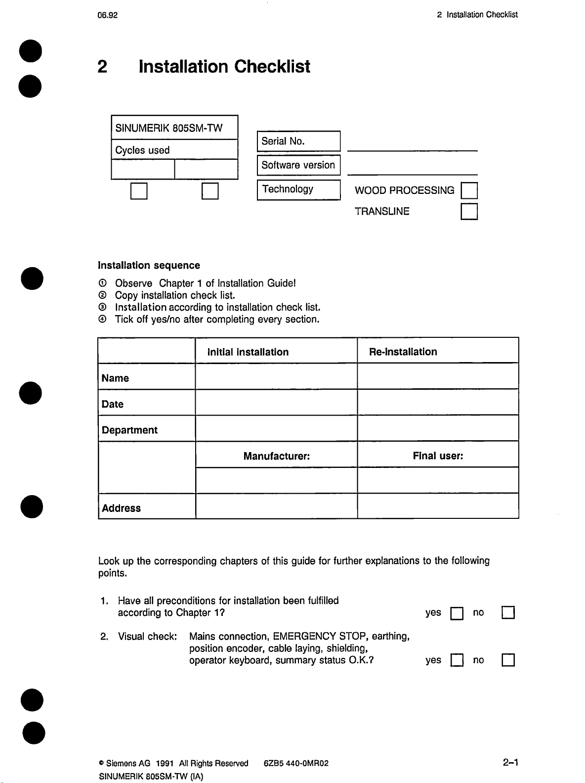
2
Installation
SINUMERIK
Cycles
Installation
©
Observe
Copy
©
Installation
®
Tick
©
off
805SM-TW
used
sequence
Chapter
installation
according
yes/no
after
of
1
Installation
check
to
completing
Initial
Checklist
Serial
Software
Technology
Guide!
list.
installation
every
installation
No.
check
section.
version
list.
WOOD
TRANSLINE
PROCESSING
Re-Installation
|
|
Name
Date
Department
Address
Lookupthe
points.
all
Have
1
.
according
Visual
2.
corresponding
preconditions
Chapter
to
check:
Mains
position
operator
Manufacturer:
chapters
installation
for
1?
connection,
encoder,
keyboard,
guide
this
of
fulfilled
been
EMERGENCY
laying,
cable
summary
for
further
STOP,
shielding,
status
explanations
earthing,
O.K.?
Final
to
yes
yes
user:
the
following
no
no
®
Siemens
SINUMERIK
AG
1991
All
805SM-TW
Rights
(IA)
Reserved
6ZB5
440-0MR02
2-1
Page 22
Installation
2
Checklist
06.92
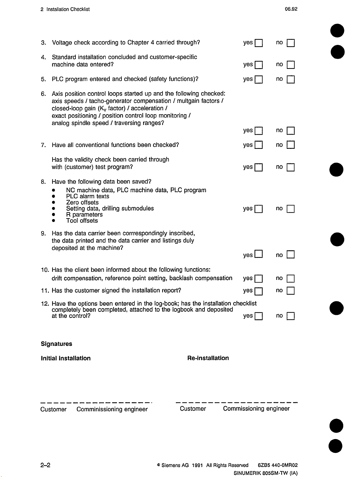
Voltage
3.
Standard
4.
machine
PLC
5.
Axis
6.
axis
closed-loop
exact
analog
Have
7.
Has
with
Have
8.
•
•
•
•
•
•
check
installation
data
program
position
speeds
positioning
control
/
gain
spindle
all
conventional
validity
the
(customer)
following
the
machine
NC
alarm
PLC
Zero
offsets
Setting
R
Tool
data,
parameters
offsets
according
Chapter
to
concluded
entered?
and
entered
tacho-generator
(Kv
position
/
speed
check
test
data
data,
texts
drilling
checked
loops
started
factor)
/
control
traversing
/
functions
carried
been
program?
been
PLC
submodules
4
carried
customer-specific
and
(safety
and
up
compensation
acceleration
monitoring
loop
ranges?
been
checked?
through
saved?
machine
data,
through?
functions)?
following
the
multgain
/
/
program
PLC
/
checked:
factors
/
yes
yes
yes
yes
yes
yes
yes
no
no
no
no
no
no
no
Has
9.
1
0.
1
1
12.
Signatures
Initial
the
the
data
deposited
Has
the
compensation,
drift
Has
the
.
Have
completely
the
at
installation
data
printed
at
client
customer
options
the
been
control?
carrier
and
machine?
the
been
signed
been
completed,
correspondingly
been
data
the
informed
reference
the
enteredinthe
carrier
about
point
and
the
setting,
installation
attached
inscribed,
listings
following
backlash
report?
log-book;
logbook
the
to
duly
functions:
compensation
has
the
installation
and
deposited
Re-installation
yes
yes
yes
checklist
yes
ED
no
no
no
no
Customer
2-2
Comminissioning
engineer
®
Siemens
Customer
AG
1991
Commissioning
Rights
All
Reserved
6ZB5
SINUMERIK
engineer
440-0MR02
805SM-TW
(IA)
Page 23
06.93
2
Installation
Checklist
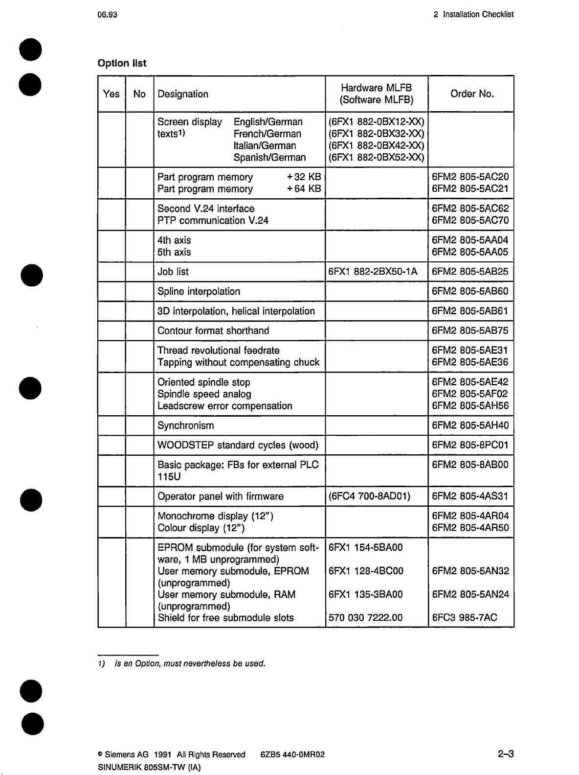
Option
Yes
list
No
Designation
Screen
texts1)
Part
Part
Second
PTP
4th
5th
Job
Spline
3D
Contour
display
program
program
V.24
communication
axis
axis
list
interpolation
interpolation,
format
English/German
French/German
Italian/German
Spanish/German
memory
memory
interface
V.24
helical
interpolation
shorthand
Hardware
(Software
(6FX1
(6FX1
(6FX1
(6FX1
32
KB
+
KB
64
+
882-2BX50-1A6FM2
6FX1
MLFB
MLFB)
882-0BX12-XX)
882-0BX32-XX)
882-0BX42-XX)
882-0BX52-XX)
Order
6FM2
6FM2
6FM2
6FM2
6FM2
6FM2
6FM2
6FM2
6FM2
No.
805-5AC20
805-5AC21
805-5AC62
805-5AC70
805-5AA04
805-5AA05
805-5AB25
805-5AB60
805-5AB61
805-5AB75
Thread
Tapping
Oriented
Spindle
Leadscrew
revolutional
without
spindle
speed
analog
error
Synchronism
WOODSTEP
package:
Basic
standard
FBs
115U
Operator
Monochrome
Colour
display
EPROM
1
ware,
User
MB
memory
with
panel
display
(12”)
submodule
unprogrammed)
submodule,
(unprogrammed)
User
memory
submodule,
(unprogrammed)
Shield
for
submodule
free
feedrate
compensating
stop
compensation
cycles
external
for
firmware
(12”)
(for
system
EPROM
RAM
slots
chuck
(wood)
PLC
soft¬
(6FC4
6FX1
6FX1
6FX1
030
570
700-8AD01)
154-5BA00
128-4BC00
135-3BA00
7222.00
6FM2
6FM2
6FM2
6FM2
6FM2
6FM2
6FM2
6FM2
6FM2
6FM2
6FM2
6FM2
6FM2
6FC3
805-5AE31
805-5AE36
805-5AE42
805-5AF02
805-5AH56
805-5AH40
805-8PC01
805-8AB00
805-4AS31
805-4AR04
805-4AR50
805-5AN32
805-5AN24
985-7AC
1)
®
Siemens
SINUMERIK
is
an
Option,
AG
must
All
1991
805SM-TW
neverthelessbeused.
Rights
Reserved
(IA)
62B5
440-0MR02
2-3
Page 24
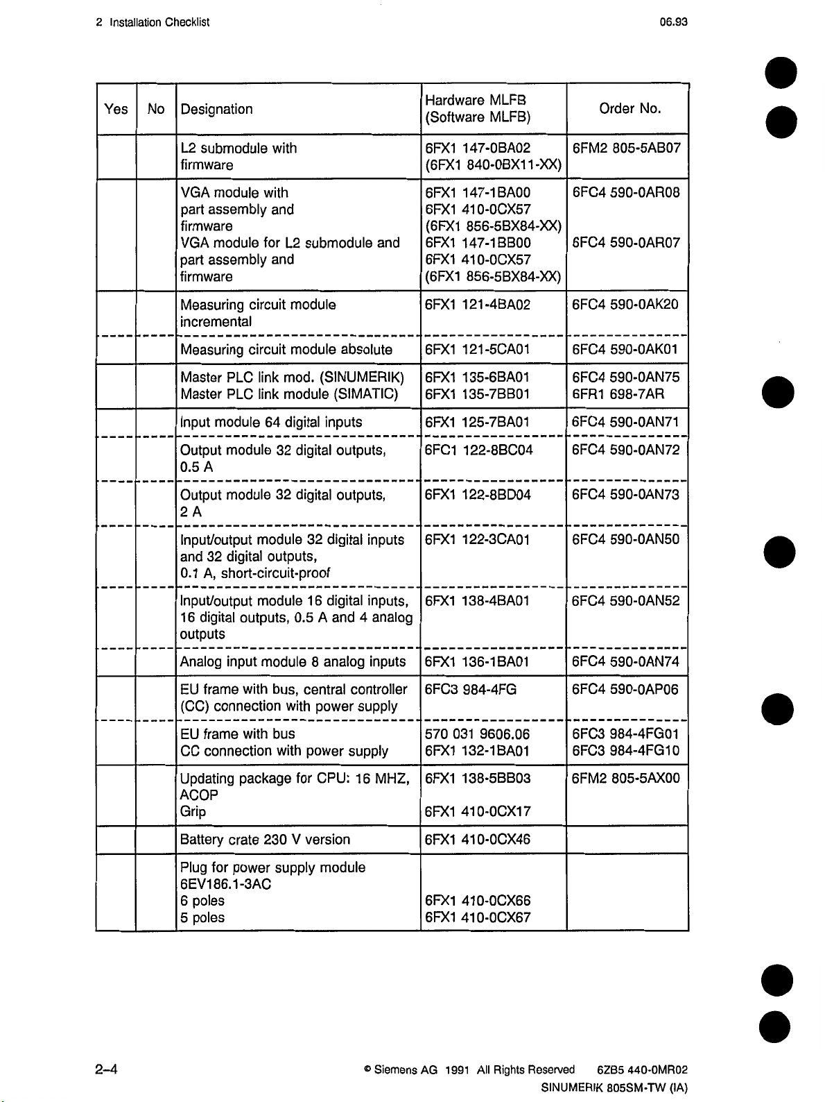
2
Installation
Checklist
06.93
Yes
Designation
No
L2
firmware
VGA
part
firmware
VGA
part
firmware
Measuring
incremental
Measuring
Master
Master
Input
Output
0.5
Output
2
submodule
module
assembly
module
assembly
PLC
PLC
module
module
A
module
A
with
with
and
for
and
circuit
circuit
link
link
64
32
32
L2
submodule
module
module
mod.
(SINUMERIK)
module
digital
inputs
digital
digital
and
absolute
(SIMATIC)
outputs,
outputs,
Hardware
(Software
6FX1
147-0BA02
(6FX1
(6FX1
6FX1
6FX1
(6FX1
6FX1
6FX1
6FX1
6FX1
6FX1
6FC1
6FX1
840-0BX11-XX)
147-1BA00
6FX1
41
6FX1
856-5BX84-XX)
147-1BB00
410-0CX57
856-5BX84-XX)
121-4BA02
121-5CA01
135-6BA01
135-7BB01
125-7BA01
122-8BC04
122-8BD04
0-0CX57
MLFB
MLFB)
Order
6FM2
6FC4
6FC4
6FC4
6FC4
6FC4
6FR1
6FC4
6FC4
6FC4
No.
805-5AB07
590-0AR08
590-0AR07
590-OAK20
590-0AK01
590-0AN75
698-7AR
590-0AN71
590-0AN72
590-0AN73
Input/output
32
and
0.1
A,
Input/output
digital
16
outputs
Analog
EU
frame
(CC)
connection
EU
frame
CC
connection
Updating
module
digital
outputs,
short-circuit-proof
module
outputs,
input
module
with
with
package
ACOP
Grip
230
for
crate
power
Battery
Plug
6EV186.1-3AC
poles
6
poles
5
0.5
bus,
with
bus
with
for
V
supply
digital
32
16
digital
and
A
analog
8
central
power
power
CPU:
version
module
inputs
inputs,
4
analog
inputs
controller
supply
supply
16
MHZ,
6FX1
6FX1
6FX1
6FC3
570
6FX1
6FX1
6FX1
6FX1
6FX1
6FX1
031
122-3CA01
138-4BA01
136-1BA01
984-4FG
9606.06
132-1BA01
138-5BB03
410-0CX17
410-0CX46
410-0CX66
410-0CX67
6FC4
6FC4
6FC4
6FC4
6FC3
6FC3
6FM2
590-0AN50
590-0AN52
590-0AN74
590-0AP06
984-4FG01
984-4FG10
805-5AX00
2-4
®
Siemens
AG
1991
All
Rights
Reserved
SINUMERIK
6ZB5
440-0MR02
805SM-TW
(IA)
Page 25
06.93
Modulo
3
Overview
3
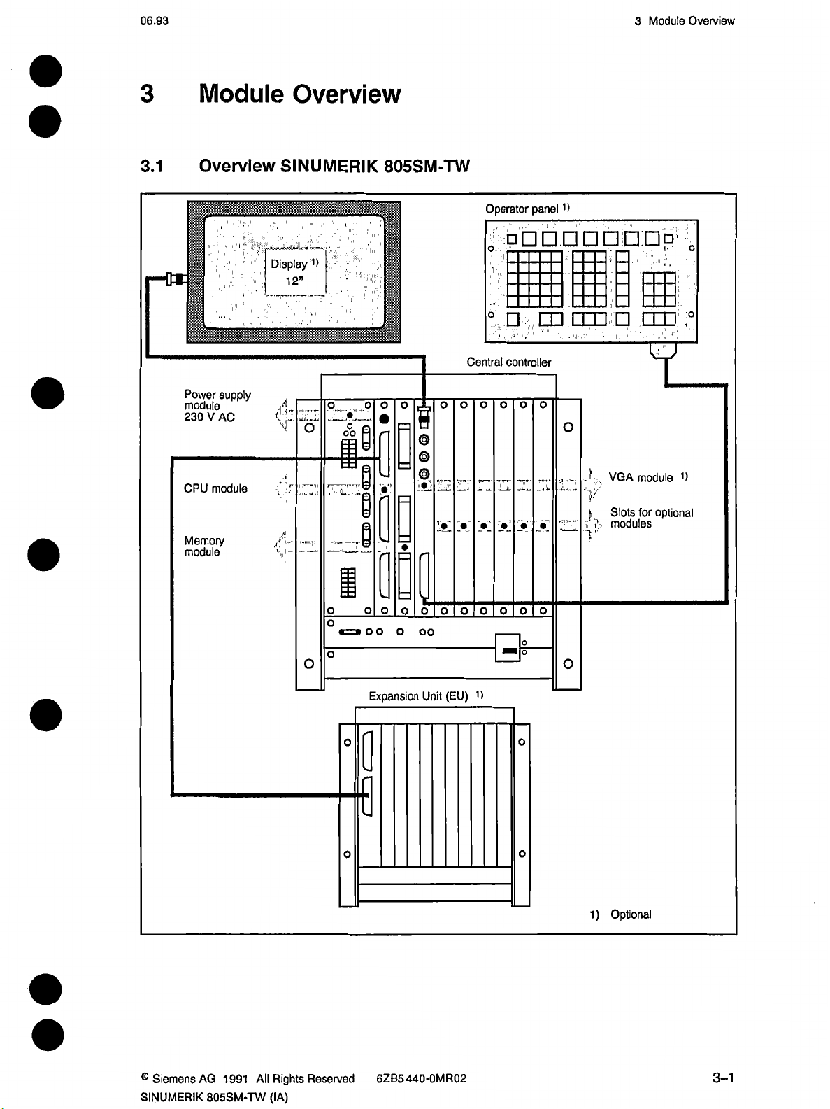
3.1
Module
Overview
_
l"
supply
V
AC
modulo
I
:
Power
module
230
CPU
Memory
module
Overview
SINUMERIK
•
Display
’ii
12”
d
f.f
V
A
v-
1>
—
”
|
§
oo
.
805SM-TW
o o
O
i
A
V
SI
A
Central
o
II
Hi
Operator
.
v®.\W
controller
o
o
n
o
777
panel
'
o
H
1>
o
J;
y
;
(,
1
VGA
,
Slots
modules
1?
1.
module
optional
for
oo
o
o
1>
o
o
o
o
o
o
o
o
o
)
Optional
1
o
o
o
o
«=»oo
o
o
o
0
o
Expansion
o
o
oo
(EU)
Unit
®
Siemens
SINUMERIK
AG
All
1991
805SM-TW
Rights
(IA)
Reserved
62B5440-0MR02
3-1
Page 26
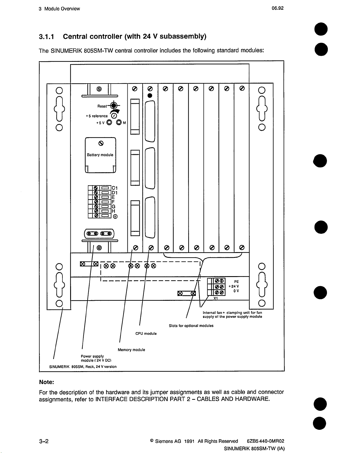
3
Module
3.1.1
Overview
Central
controller
(with
24
V
subassembly)
06.92
SINUMERIK
The
o
o
805SM-TW
Reset
reference
%
@
+
5
<9
Battery
module
C=3
S
~<5
central
C1
D1
E
G
©
controller
0
0
includes
0
0
the
following
0
0
standard
0
modules:
0
o
O
o
o
SINUMERIK
Note:
description
the
For
assignments,
M
805SM,
refer
(<£3)
I&
supply
Power
(
24
module
24
Reck,
of
the
INTERFACE
to
(BZg))
|
®
®
I
T
Memory
DC)
V
version
V
hardware
,0
CPU
module
and
module
its
0
jumper
DESCRIPTION
0 0
DO
optional
for
Slots
assignments
CABLES
2
PART
-
I
/
7
Internal
supply
modules
as
0
well
0®
00
00
X1
of
fan-*-
the
0
0
PE
V
24
+
V
0
clamping
supply
power
cable
as
HARDWARE.
AND
unit
and
o
o
for
fan
module
connector
3-2
©
Siemens
AG
1991
All
Rights
Reserved
SINUMERIK
6ZB5
440-0MR02
805SM-TW
(IA)
Page 27
06.92
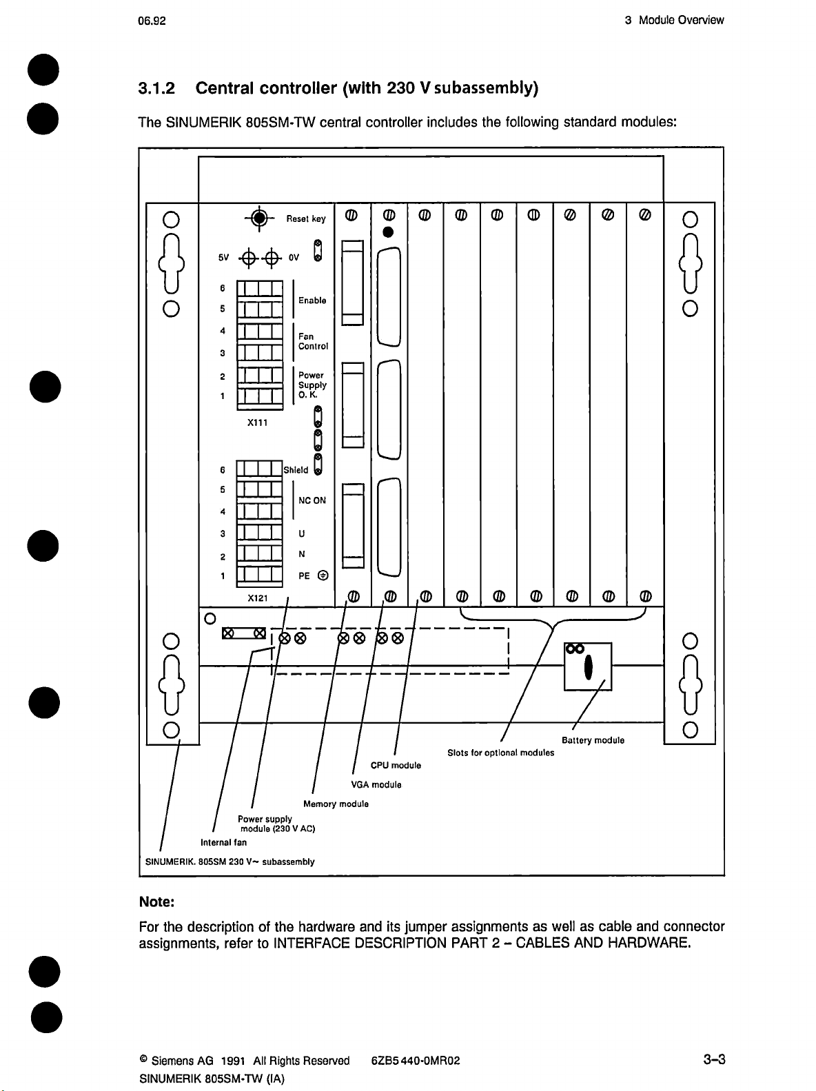
3.1.2
Central
controller
(with
230
V
subassembly)
3
Module
Overview
SINUMERIK
The
o
o
o
o
805SM-TW
+
5V
6
5
4
3
2
EH
1
Ml
X111
6
s
TTT
4
3
2
1
X121
00
DO
I
0®
Reset
0V
Enable
Fan
Control
Power
Supply
0.
Shield
key
K.
NC
U
N
PE
central
ON
©
controller
©
,©
©®®
©
,©
includes
©
,©
©
©
following
the
©
©
I
I
©
©
standard
©
©
©
© ©
modules:
©
o
o
o
o
Internal
SINUMERIK.
Note:
For
assignments,
®
Siemens
SINUMERIK
805SM
the
description
AG
805SM-TW
fan
230
refer
1991
supply
Power
(230
module
subassembly
V-
the
of
INTERFACE
to
All
Rights
(IA)
Memory
module
AC)
V
hardware
Reserved
CPU
module
VGA
module
and
its
jumper
DESCRIPTION
6ZB5440-0MR02
optional
tor
Slots
assignments
2
PART
-
modules
Battery
wellascable
as
CABLES
»
7
module
AND
HARDWARE.
and
o
connector
3-3
Page 28
06.92
Voltage
4
and
Validity
Check
4
4.1
4.1.1
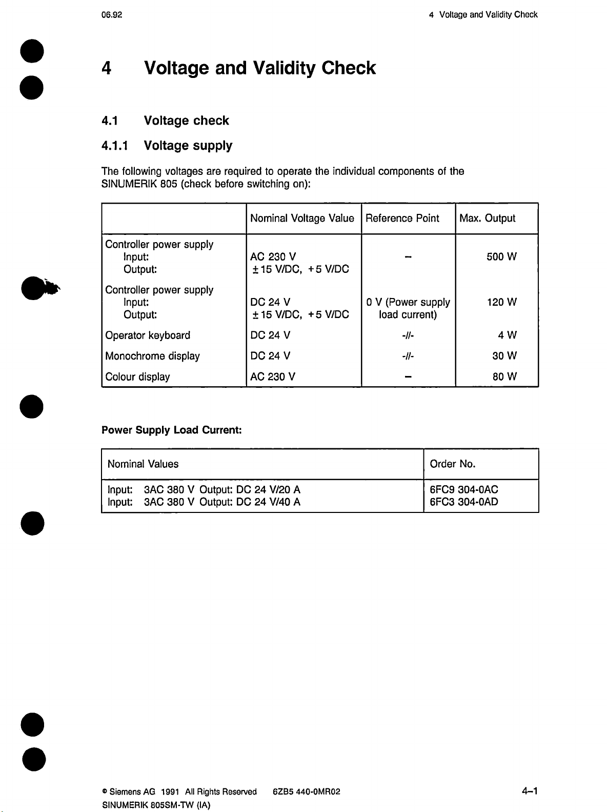
The
Voltage
Voltage
Voltage
following
SINUMERIK
Controller
power
Input:
Output:
Controller
power
Input:
Output:
Operator
keyboard
Monochrome
voltages
(check
805
supply
supply
display
and
check
supply
are
before
Validity
required
switching
Nominal
AC
±15
DC
±15
DC
DC
to
operate
230
V/DC,
24
V/DC,
24
24
on):
Voltage
V
V
V
V
Check
the
individual
Value
+5V/DC
V/DC
+5
components
Reference
0
(Power
V
current)
load
-//-
-II-
Point
supply
of
the
Max.
Output
500
W
120
W
4
W
W
30
Colour
Power
Nominal
Input:
Input:
display
Supply
Values
3AC
3AC
Load
380
380
Current:
V
Output:
V
Output:
230
AC
DC24V/20
24
DC
V/40
W
V
Order
No.
304-0AC
A
A
6FC9
6FC3
304-0AD
80
®
Siemens
SINUMERIK
AG
1991
All
B05SM-TW
Rights
(IA)
Reserved
6ZB5
440-0MR02
4-1
Page 29
Voltage
4
and
Validity
Check
06.92
4.1.2
When
the
following
PLC
•
User
•
Machine
•
Part
•
Tool
•
parameters
R
•
Zero
•
Setting
•
Drilling
•
memory
RAM
Battery
Hardware
battery
The
right
of
V.
24
version.
When
the
V,
2.7
NC
Battery
control
data:
program
user
(PLC
texts
data
programs
offsets
offsets
data
submodules
buffering
module
MLFB:
module
central
the
control
1
Alarm
buffering
switched
is
alarm
MDs
(NC
is
410-0CX46
6FX1
(three
controller
is
switched
(battery
of
off,
the
and
PLC
and
PLC
obtained
mignon
V
1.5
the
of
on,
the
error)
is
RAM
MDs)
battery
a
cells
V.
battery
memory
memory
version
RAM
message
by
230
displayed.
must
texts)
module.
connected
in
or
voltage
is
battery-buffered
be
series)
in
power
the
checked
cyclically.
situatedinthe
is
supply
unit
If
it
save
to
of
drops
the
bottom
the
below
When
that
sure
Battery
Buffer
Note:
Used
monitoring
the
batteries
type:
period:
batteries
has
3
x
>
must
1
.5
1
year
be
activated,
been
have
mignon
V
disposed
the
correct
cells,
according
of
replace
polarity.
LR6
batteries
the
(commerically
presently
to
the
when
available)
regulations.
valid
control
is
on.
Make
4-2
Siemens
•
AG
1991
All
Rights
Reserved
SINUMERIK
6ZB5
440-0MR02
805SM-TW
(IA)
Page 30
06.92
Voltage
4
and
Validity
Check
4.2
The
unit
all
first
(e.g.
switching
error
an
"frozen”
unit
•
•
After
displayed
If
with
4.3
4.3.1
CPU
The
axes
the
The
LED
switching
CPU
•
EPROM
•
Incorrect
•
Incorrect
•
Faulty
•
CPU
•
CPU
•
Starting
be
may
all
via
during
switched
components
external
NC-ON
on
the
occurs
opening
Validity
CPU
monitoring
shows
LED
are
stopped
while
is
on
is
on
or
error
error
machine
jumper
module
loop
in
previously
sequence
on
are
components
switch).
control,
the
period
during
the
screen.
check
the
status
and
the
the
control
being
illuminated
data
assignment
or
back
loop
in
the
of
as
follows:
simultaneously
are
switched
opening
an
initialization
of
period
PLC
panel
whereas
of
the
of
outputs
booting
is
during
monitoring
initialization,
control.
control,
switched
(e.g.
on
screen
of
are
up
operation
showing
the
central
When
switched
(power
has
opening
on
via
main
software
controller.
corresponding
the
monitoring
off.
on
routine).
if
one
of
been
activated
screen
switch),
is
The
the
following
then
version
alarm
being
LED
the
central
languages
and
will
be
activated
on
is
still
conditions
unit
is
displayed
(LED
on),
after
applies:
4.3.2
the
With
(EPROM
error
an
If
EPROM
SINUMERIK
module)
occurs
check
is
carried
during
805SM,
out
the
cross-check
a
every
time
cross-check
the
sum
sum
control
test,
test
the
of
the
is
switched
control
system
is
not
program
on.
booting
memory
up.
®
Siemens
SINUMERIK
AG
All
1991
805SM-TW
Rights
(IA)
Reserved
6ZB5
440-0MR02
4-3
Page 31

Voltage
4
and
Validity
Check
06.92
4.3.3
functions
The
Power
•
Central
Monitor
Operator
Cables
•
Interface
Coaxial
CPU
•
case
In
above:
Miniature
•
(see
Adjustment
•
(see
SCREEN
•
DISABLE
•
DISABLE
•
Validity
of
these
supplies
controller
keyboard
are
connected
cable
cable
from
running
is
an
error
of
fuses
INTERFACE
possibilities
INTERFACE
BLANK
KEYBOARD
KEYBOARD
check
O.K.
from
(-»ÿ
the
for
of
components
:
230
unit.
230
AC
:
DC
Measure
+
:
24
Measure
central
central
red
following
operator
DESCRIPTION
controller
LED
monitor
for
DESCRIPTION
interface
signal
interface
PARTLY
central
depend
V~
(A
24
controller
is
items
keyboard
or
power
V
V
voltage
V
from
voltage
not
PART
PART
(Q79.6)
signal
interface
+
for
for
on)
must
controller-monitor-operator
following
the
on
V
external
24
colour
unit
monitor
supply
monochronous
(make
power
(make
(VGA
(VGA
be
and
2
2
(Q79.7)
signal
sure
supply
sure
module
module)
checkedinaddition
monitor
CABLES
-
CABLES
-
suppy
with
load
X141)
to
that
that
monitor
AND
AND
conditions:
the
to
220
V
or
monitor
polarity
current
polarity
keyboard
to
to
HARDWARE)
HARDWARE)
internal
24
+
is
is
the
keyboard
power
may
V
correct)
correct)
conditions
supply
be
available).
listed
4-4
©Siemens
AG
1991
All
Rights
Reserved
SINUMERIK
62B5
440-0MR02
805SM-TW
(IA)
Page 32

06.93
Voltage
4
and
Validity
Check
4.4
For
system
Restart
Restart
System
Screen
Software
operating
software
EPROM
EPROM
software
display
the
and
texts
English/German
French/German
Italian/German
Spanisch/German
Notes:
XX:
The
identifier
module
for
for
used.
on
language
again.
The
off
second
and
identification
SINUMERIK
screen
Designation
(D94
(D95
(module
(module
software
the
CPU
on
CPU
on
1
screen
is
display
)
version
defined
805SM-TW,
texts
module)
module)
2)
display
texts
by
modifying
2
restart
are
required.
(module
EPROMs
Product
570.882.0801
570.882.0802.XX
570.882.9001
570.882.901
570.882.9032.XX
570.882.9042.XX
and
number
.XX
.XX
2.XX
570.882.9052.XX
an
NO
2)
MD
is
option,
5149
bit
plug-in
1
/
it
and
0
module
Order
6FX1
6FX1
6FX1
6FX1
6FX1
6FX1
nevertheless
must
switching
for
each
number
882-0BX80-XX
882-OBX01-XX
882-0BX12-XX
882-0BX32-XX
882-0BX42-XX
882-0BX52-XX
be
the
control
©Siemens
SINUMERIK
AG
1991
All
805SM-TW
Rights
(IA)
Reserved
6ZB5
440-0MR02
4-5
Page 33

06.93
Standard
5
Installation
5
5.1
In
•
•
•
•
•
The
•
•
•
•
•
this
Standard
Standard
Section
system
The
CHECK.
The
power
AND
VALIDITY
The
devices
CABLES
The
feed
started
The
INITIALIZATION
Softkey
Key
Softkey
Enter
Softkey
up
PLC
password
Installation
installation
following
the
has
been
supply
CHECK.
have
AND
HARDWARE.
and
main
(EMERGENCY
program
user
menue
DIAGNOSTICS
MORE
INITIALIZATION
INITIALIZATION
(menu
and
preconditions
checked
all
to
components
been
jumpered
spindle
(STEP
may
expansion
press
according
drives
STOP).
5)
be
INPUT
NC
of
must
has
according
disabled
are
is
executable.
selected
key)
key
and
PLC
have
Chapter
to
been
checked
INTERFACE
to
until
as
follows
fulfilled:
been
PRECONDITIONS
according
DESCRIPTION
axis
and
the
proceeding
spindles
from
Chapter
to
the
AND
PART
have
data
VISUAL
VOLTAGE
2
-
been
area:
After
an
selected
By
pressing
a
hook.
Initialize
The
to
the
chapter
the
Initialize
The
Format
Deletion
presetting.
Format
The
part
PLC
The
internal
via
memory
PLC
part
programs
general
memory
Reset
cursor
the
START
the
WOOD
functions
FUNCTIONAL
internal
MD
user
data
setting
of
program
part
program
the
or
TRANSLINE
area
for
carried
or
area
is
memory
data,
memory
(NC
RESET
area
for
INITIALIZATION
keys.
softkey,
machine
external
cleared
memory
MD
the
the
data
through.
DESCRIPTION.
PLC
and
offsets,
tool
is
cleared
8).
user
PLC
menue
function
or
The
preset
selected
OPERATION
is
cleared
OPERATION
with
offsets,
zero
a
and
program
appears.
will
WITHOUT
the
and
WITHOUT
standard
R
directory
is
cleared.
The
various
be
executed
NC.
machine
NC
machine
parameters,
created
for
functions
and
data
are
function
data.
program
the
maximum
can
be
acknowledged
preset
according
is
described
parameters
number
with
in
or
of
®
Siemens
SINUMERIK
AG
All
1991
805SM-TW
Rights
(IA)
Reserved
6ZB5
440-0MR02
5-1
Page 34

5
Standard
Installation
06.93
General
•
All
PLC
Press
•
Notes:
MD
NC
•
displayed
TRANSLINE
With
•
TRANSLINE
simultaneously
With
•
•
•
WOOD
wood-specific
simultaneously
When
PLC
and
case
In
menu
By
-
is
module.
Now
-
Make
-
Activate
-
Now
-
RESET
are
flags
the
INITIAL
5033
after
operator
PROCESSING
starting
NC
must
service,
of
can
be
triggering
switched
control
the
sure
an
control
the
flags
of
reset
END
bit
can
1
booting
the
pressing
functions
pressing
PLC,
the
therefore
when
selected
alarm
and
on
branchesinthe
the
battery
internal
branches
0.
to
softkey
specify
up.
user
panel
the
to
the
an
as
1
pressing
RESET
(after
whether
switch
can
or
a
customer-specific
RECALL
user
the
a
customer-specific
RECALL
may
error
be
not
control
the
follows:
(battery
module
by
in
the
an
internal
customer-specific
the
the
from
MORE
and
can
switch
operator
and
MORE
because
occur
started
alarm),
the
with
no
can
by
RESET
longer
removing
key
INITIALIZATION
is
re-inserted
pressing
basic
the
menu.
Reset
the
standard
operator
keys.
the
from
panel
keys.
the
of
the
menu
operated,
be
the
on
the
menu.
starting
after
INITIAL
END
display
basic
or
standard
operator
standard
INITIALIZATION
battery
front
panel
panel
and
inactive
the
module
plate
up
the
softkey.
and
vice
operator
versa
vice
NC/PLC
INITIALIZATION
the
of
control!
appears).
operator
either
to
versa
panel
by
interface.
selected.
when
power
panel
the
by
with
control
the
supply
is
using
When
•
regard
SW3
From
•
Axis/spindle
The
however,
Thus,
1)
2)
3)
Now
In
(see
NC
data
PLC
control
to
select
Press
DATA
MD
NC
MC
MD
MDs
2000
description
MD
the
the
the
relevant
on
blocks
assignment
is
now
ensure
NC
the
operating
softkey
VALUES
2000
2004
to
in
2000
2001
2002
2003
2004
=
=
=
=
=
USER
the
in
that
MD
is
MEMORY
chapter.
memory
(see
chapter
a
permanently
it
operates
area
area
softkey
selected
specify
you
connection
axis
1st
axis
2nd
axis
3rd
axis
4th
axis
5th
available
MEMORY
as
follows:
key
by
means
which
with
SUBMODULE
may
be
ALLOCATION).
of
axis
MD
state.
together
the
is
200*).
defined
correctly
NC
function
allocated
few
A
with
page
and
wired
to
(UMS,
to
adjustments
the
cursor
which
programs,
part
machine.
keys.
measuring
available
PLC
have
to
circuit
from
program
made,
be
or
on),
SW2
encoder
and
5-2
®
Siemens
AG
1991
All
Rights
Reserved
SINUMERIK
440-0MR02
6ZB5
805SM-TW
(IA)
Page 35

06.92
4000
MD
In
description
In
MDs
5680to5684
MD
NC
with
you
specify
in
connection
568*).
to
the
which
NC
with
desired
measuring
4000).
MD
names
axis
circuit
must
encoder
or
be
specified
the
(see
spindle
description
is
Standard
5
wired
in
Installation
(see
connection
The
NC
NC
MD
programs
5680
5681
5682
5683
5684
refer
=
=
=
=
=
1st
2nd
3rd
4th
5th
to
axis
axis
axis
axis
these
axis
axis
names.
©Siemens
SINUMERIK
AG
1991
All
805SM-TW
Rights
(IA)
Reserved
6ZB5
440-0MR02
5-3
Page 36

5
Standard
5.2
Installation
installation
Axis
09.91
General
Before
trouble-free
conditions
•
•
•
•
•
•
notes:
starting
Controller
speed).
to
Speedo
voltage.
speed
The
creepage).
setpoint
The
standard
The
The
actuator
the
NC
the
with
have
must
module
adjustment:
and
current
connector
MDs
must
to
axis
battery
been
matched
The
must
be
left
The
SERVO
drive
the
installation
acting
box
fulfilled:
motor
to
maximum
controllers
be
must
be
switched
must
removed
loaded.
ENABLE
actuator
be
routine,
as
speed
must
off.
usedatthe
the
a
setpoint
(maximum
must
have
from
signal
each
in
axis
should
generator.
power,
reached
be
been
optimized
NC.
the
supplied
setpoint
axis’
drive
already
This
current
from
actuator.
have
means
characteristic
95%
at
of
overshooting
(no
NC
the
connector
been
that
the
maximum
operated
following
the
according
set
or
set
5.2.1
Position
control
maximum
The
*
•
•
Example:
•
•
•
•
Checking
and
loop.
speeds.
following
Traversing
Polarity
NC
NC
NC
Disable
MD
MD
axis
of
564*
564*
is
NC
speed
An
conditions
direction
controller
to
and
and
control
incorrectly
bit
1
bit
2
traverse
connect
adjusting
directions
set
must
the
of
setpoint
=0
0
=
in
control
thus
feed
speed
positive
the
battery.
must
direction
be
fulfilled
axis
the
control
always
before
(as
stated
voltage
direction
direction
checked
be
resultsinuncontrolled
operation:
customer
axis
a
positive
for
when
starting
the
by
positive
of
before
or
movement
setpoint
the
feed
closing
axis
according
the
movements
value
axes
position
ISO)
to
is
set.
at
5-4
«
Siemens
AG
1991
All
Rights
Reserved
SINUMERIK
6ZB5
440-0MR02
805SM-TW
(IA)
Page 37

06.92
value
Preset
by
means
USet
positive
of
approx.
set
battery
1
V
N,
box
/
Standard
5
Installation
Note:
no
If
check
5.2.2
pulses
the
Position
arrive
encoder
the
at
cable
control
actual
or
the
resolution,
Positive
direction
NC
MD
value
display,
encoder
no
564*.1
itself.
1
=
NC
input
yes
no
564*.2
MD
resolution
-
1
(Disable
Positive
value
and
connect
actual
display
END
battery
yes
box
NC)
The
input
bits
5002.0
closing
The
the
the
following
position
Maximum
<
£
<
Axes
2.4
24
240
not
m/min
m/min
m/min
involved
Maximum
<
4.5
m/min
<
:£
45
450
m/min
m/min
Note:
As
the
position
the
highest
resolution
5002.2)
to
position
connection
control
speed
axis
in
speed
axis
control
maximum
(NC
MD
be
must
control
loops
exists
resolution:
2D/3D
interpolation
resolution
speed.
bits
5002.4
entered
(plug
between
Position
0.5-10-4
0.5-10-3
0.5-10-2
Position
0.5-10-4
0.5-10-3
0.5-10-2
is
in
valid
5002.6)
to
(see
NC
setpoint
the
axis-specific
the
control
mm
mm
mm
also
can
control
mm
mm
mm
all
for
and
5002
MD
connector).
resolution
assigned
be
resolution
axes,
mustbeset
it
position
allowed
for
maximum
as
control
bit
speed
follows:
according
resolution
(NC
combinations)
(NC
to
MD
the
280*)
axis
MD
before
and
with
®
Siemens
SINUMERIK
AG
1991
All
805SM-TW
Rights
(IA)
Reserved
6ZB5
440-0MR02
5-5
Page 38

Standard
5
5.2.3
axis-specific
The
maximum
and
the
mechanical
Installation
Maximum
maximum
speeds
are
axis
speed
speeds
determined
design
(see
must
by
MD280*).
NC
be
entered
the
manufacturer
NC
in
according
MD
280*.
to
The
particular
the
06.93
axis-specific
requirements
5.2.4
The
setpoint
Make
The
The
operation
The
Definition
axis-specific
speed
sure
output
setpoint
the
maximum
Conversion
maximum
The
of
the
drive
a)
Maximum
Input
via
The
maximum
The
b)
e.g.
Input
drive
5
via
maximum
(NC
an
are
specified
is
limit
additional
entered
that
limits
permissible
input
to
setpoint
controller.
permissible
MD
NC
axis
controller
V:
NC
MD
of
MD
set
data:
must
268*
268*:
268*).
speed
maximum
speeds
control
by
via
operates
the
NC
in
NC
setpoint
V
10
be
input
:
8192
is
DAC
MD
MD
8192
=
entered
voltage
units
reached
required
reserve
of
268*.
268*
10V.
is
units.
a
with
8192
V
10
setpoint
by
approx.
of
setpoint
the
NC
The
must
according
the
drive
of
V
10
=
only
at
maximum
V
5
the
customer
(10V)
thus
be
not
the
to
controllers
V
9.5
setpoint
4096
=
(NC
available.
5%
is
by
or
restricts
reached.
maximum
because
speed
MD
drive
the
output
the
permissible
V:
10
control
the
of
voltage
280*)
controller.
voltage.
<
assigned
are
input
reserve
V,
10
During
voltage
of
5
to
a
%.
The
better
5.2.5
Enter
•
NC
NC
Subsequent
•
Traverse,
depending
gauge.
Max.
actuator
via
Input
Speedo
setpoint
NC
compensation:
should
higher
at
Variable
the
values
(traversing
368*
MD
MACHINE
value
for
example,
on
voltage:
input
268*:
MD
generally
setpoint
voltages.
incremental
NC
control:
1000
input
set
MD
path
for
DATA.
the
5
V
4096
The
maximum
4.5
at
be
set
as
high
possible
as
weighting
364*
(pulse
variable
for
increments
resolution(1increment
number
for
incremental
JOG-INC
the
in
V.
variable
weighting)
1
unit
=
speed
because
incremental
mode;
calculate
(IS))
shouldbereached
control
as
and
behaviour
weighting)
described
the
check
in
path
with
Chapter
is
and
a
dial
5-6
©Siemens
AG
1991
All
Rights
Reserved
SINUMERIK
440-0MR02
6ZB5
805SM-TW
(IA)
Page 39

09.91
Standard
5
Installation
5.2.6
With
this
the
axis
Closing
control
(fuses,
A
Causes
Incorrect
control
bits)
Position
loop
control
switched
servo
uncontrolled
of
polarity
(incorrect
the
position
off,
disable).
the
In
EMERGENCY
machineorthe
of
position
NC
loop
not
plug
Disable
event
movements
speed
or
machine
closed
control
the
in
the
an
of
STOP
operator.
data
loop
setpoint
uncontrolled
connector
axes,
other
immediately
Axis
Axis
measuring
movement
and
switch
on
CAUTION
movement
rule
to
traverses
traverses
at
at
device
(e.g.
cancel
out
Symptoms
loose
any
the
control
feed
the
of
danger
any
maximum
constant
does
not
coupling)
other
and
axis,
speed
low
follow
disables
actuator.
press
the
to
speed,
the
for
axis
setpoint
No
Control
Speedo
•
Speedo
•
Incorrect
•
Ky
•
5.2.7
setpoint
The
correct.
If
the
•
The
-
-
-
-
-
speed
at
fault
loop
feedback
feedback
optimization
factor
Axis
Traverse
FEED
following
Axis-specific
axis
No
follow-up
No
Controller
Feedrate
great
too
traverses
cable
must
the
HOLD
interface
disable
enable
override
controller
interrupted
incorrect
with
in
plugged
be
axisatlow
message
signals
general
and
operation
switch
polarity
JOG
mode
in.
speed
appears,
are
required:
enables
feed
not
at
The
with
check
0%
Bonding
causes
monitoring
Axis
Axis
control
the
direction
the
frame,
to
response
traverses
vibration
direction
keys.
interface
open
from
at
constant
and
pronounced
pulse
and
signals.
short-circuit
or
measuring
speed
low
oscillation
weighting
circuit
(drift)
must
be
e
Siemens
SINUMERIK
AQ
1991
All
805SM-TW
Rights
(IA)
Reserved
6ZB5
440-0MR02
5-7
Page 40

Standard
5
Installation
06.92
Continuous
•
-»
execute
alarms
If
•
5.2.8
multiplication
A
speed.
the
Axes
gain
according
Multgain
Thus,
specified
having
factor.
Multgain
Example:
Max.
>
=
>
=
+
drift
are
factor
is
it
setpoint.
traversed
Therefore
the
to
=
speed
axis
(MS)
1
unit
setpoint
sign
or
-
compensation
activated
possible
in
-»
NC
MD
(multgain
to
with
the
multiplication
following
formula:
Vmax
=
Vmax
2-0.5-10*3
=
voltage
at
(ÿCy
the
(see
see
Chapter
260*
MD
NC
traverse
continuous
3
107
unitSMS/mjn]
[1000
20m/min
Vmax
mm
=
=
9.5
)
field
272*)
MD
NC
MONITORING.
has
260*)
axes
path
factor
>
1-10-3
=
V
different
with
control
(multgain)
position
mm
to
be
must
control
>
=
entered
maximum
have
the
be
must
resolution
=
Vmax
calculate
to
speeds
same
calculated
[V]
Umax
[V]
10
0.5-1
20000
(1000units/min]
the
making
position
for
mm
O'3
setpoint
full
control
each
axis
use
loop
of
Multgain
Note:
an
With
and
entered
a
With
and
Additional
1)
metric
entered
Input
Measuring
1-10*3
Max.
Speedo
Conversion
Vmax
Multgain
=
input
inch
as
Vmax
input
as
Vmax
multgain
system
mm
speed
=
resolution
system
=
compensation
from
10
m/min
=
20000
system
the
in
system
the
in
calculation
resolution
10
"Vmin
Vmax
Vmax
10000
1Q7
3
-
[1000
unitsMS/min]
(IS)
the
formula.
(IS)
the
formula.
(IS)
=
MD
-*•
9V
to
measuring
to
10000
=
3
[1000
maximum
maximum
examples:
1-10*3
(MS)
=
280*
=
system
[1000
107
units
MS/min]
speed
mm
0.5-1
10000
units
(MD
speed
(MD
-»
unit
1
mm
0*3
[1000
resolution:
MS/min]
9.5
10
(IS)
->
units
10
[V]
[V]
280*)
280*)
unit
1
[V]
9
[V]
=
must
must
1-10*3
=
(MS)
IS/min]
1425
converted
be
be
mm
=
2700
=
['
1000
to
converted
2-0.5-10*3
min
units(MS)
mm/min
inch/min
to
mm
=
]
5-8
®
Siemens
AG
1
991
All
Rights
Reserved
SINUMERIK
6ZB5
440-0MR02
805SM-TW
(IA)
Page 41

09.91
2)
Input
Measuring
MO*4
Max.
Speedo
system
resolution
system
mm
speed
=
m/mjn
4
compensation
(IS)
resolution
-*ÿ
MD
9V
to
1-10-3
=
(MS)
280*
mm
0.5-10-4
=
4000
=
1
unit
mm
[1000
(IS)
units
1-10-3
=
(MS)
1
unit
ls/minl
mm
2-0.5-10-4
=
5
Standard
Installation
mm
=
Conversion
Vmax
Multgain
3)
Input
Measuring
1-10-3
Max.
Speedo
Conversion
vmax
Multgain
from
4
=
=
m/min
=
system
mm
speed
=
resolution
system
400
=
compensation
from
-inch
400
min
=
to
Vmax
40000
40000
(IS)
resolution
inch/mjn
to
to
Vmax
_
400.jncti.
10160
measuring
[1000
units
•
3
107
[1000
units
1-10-4
=
(MS)
MD
280*
9V
measuring
min
107
3
[1000
units
system
MS/mjn]
MS/min]
inch
0.5-1
=
=
system
mm
25.4
inch
MS/min]
resolution:
-»ÿ
1
unit
mm
0-3
[1000
4000
resolution:
10160
a
9
10
(IS)
1
units
9
10
[V]
[V]
=
unit
J22L
min
[V]
[V]
675
=
0'4
(MS)
inch
=
1-1
MS/min]
1
01
=
2657
=
0-3
2-0.5-1
60[1000
mm
units
=
Ms/mjn]
4)
Input
Measuring
Max.
Speedo
Conversion
Vmax
Multgain
system
speed
resolution
system
20
=
compensation
from
20
=
m/min
=
(IS)
resolution
m/min
to
to
Vmax
20000
=
787.4
1-10-3
=
(MS)
MD
280*
9V
measuring
mm
min
•
1Q7
3
[1000
units
mm
0.5-10-4
=
20000
=
system
inch
25.4
MS/min]
unit
1
inch
[1000
resolution:
787.4
=
mm
(IS)
->
unit
9
10
1-10-3
=
unit
1
IS/min]
-inHil
[V]
[V]
(MS)
min
mm
787.4
=
34290
=
=
2-0.5-10-4
[1000
jnch
units
Ms/min]
®
Siemens
SINUMERIK
AG
1991
All
805SM-TW
Rights
(IA)
Reserved
6ZB5
440-0MR02
5-9
Page 42

Standard
5
Installation
09.91
5.2.9
To
gain)
If
the
machine
The
•
•
The
Kv
Servo
achieve
factor
factor
Kv
loads.
maximum
drive
the
time,
(rise
quality
the
factor
Kv
=
gain
negligible
only
252*)
MD
NC
high,
is
too
permissible
configuration
acceleration
of
the
machine.
defined
is
Speed
Following
error
m/min
mm
empirical
an
If
overshootingorinstability.
value
is
Association
the
for
factor
Kv
contour
required.
is
however,
Kv
and
as
the
Kv
deviations
it
factor
depends
braking
unitofthe
of
German
is
factor
results
ability),
[m/min]
[mm]
factor
K
known
continuous
with
instability,
in
on:
according
Engineers
for
the
path
overshoots
the
to
(VDI)
machine,
control,
and
standard
this
set
a
possibly
value
high
and
(servo
Kv
excessive
check
for
factor
Kv
Reduce
maximum
drive
the
remains
setting
acceleration
factor.
Kv
below
Proper
precondition
the
(NC
acceleration
The
electrical
its
MD
speed
276*).
must
current
controller
for
the
The
overshoot
therefore
threshold.
correct
optimization
factor
Kv
is
setting.
behaviouriscrucial
enough
set
low
be
for
ensure
to
evaluating
that
the
the
5-10
®
Siemens
AG
1991
All
Rights
Reserved
SINUMERIK
6ZB5
440-0MR02
805SM-TW
(IA)
Page 43

09.91
Enter
the
servo
gain
according
to
the
following
conversion
formula
in
NC
MD
5
Standard
252*:
Installation
1
=
Kv
s)
(0.01
Kv
The
numerical
To
evaluate
selected
path
Measure
=
correctly,
control.
the
oscilloscope.
[V]
nset
[m/min]
1
[mm]
1
1000
16.66
value
starting
the
use
setpoint
Traverse
[mm/min]
[mm]
1
-
0.01
1666
conditions
the
voltage
at
_
1
s
thus
nset
feedrates.
entered
and
to
is
dynamically
various
Speed
Following
1000
for
determine
least
speed
the
error
1
=
s
60
the
Kv
factor
whether
favourable
controller
16.66
1.
the
axis
with
1
—
s
maximum
set
contributes
that
an
Oszillomink
has
value
continuous
to
storage
or
been
[V]
nSet
Deceleration
gains.
in
particular
can
be
observedonthe
oscilloscope
or
Oszillomink
at
high
[ms]
t
[ms]
t
voltage
®
Siemens
SINUMERIK
AG
All
1991
805SM-TW
Rights
(IA)
Reserved
6ZB5
440-0MR02
5-11
Page 44

Standard
5
Installation
09.91
Overshooting
Acceleration
•
Excessive
•
Faulty
•
•
•
•
For
one.
Ky
factor
Refer
determine
and
speed
Mechanical
Canting
Load
fluctuations
safety
reasons
control
the
to
the
negative
also
may
too
rise
time
controller
backlash
mechanical
of
select
Axes
service
traverse
size
display
of
have
high
(current
speed
of
(reoptimization
components
(vertical
Ky
a
cooperating
for
following
the
directions
one
axis)
factor
the
if
following
the
of
threshold
circuit
that
continuous
in
same
the
individual
error.
The
drift
the
causes:
reached)
is
necessary)
be
may
least
at
is
path
Ky
factor.
(see
axes
displayed
compensated.
is
10%
lower
control
diagnostics
value
is
than
must
the
the
maximum
have
description
both
in
same
possible
selection)
for
the
|
to
positive
Finally,
Exact
the
If
value
5.2.10
The
This
the
Consult
Enter
These
check
continuous
following
same
discrepancies
potentiometer.
Acceleration
axes
are
b
permits
same
time.
the
value
this
values
the
entered
path
error
occur,
accelerated
10-2
precise
customer
are
and
NC
in
normally
Ky
control
must
differences
the
and
[m/s2].
fast
to
determine
MD
276*
between
factor
requires
occur
braked
running
the
(provided
of
axes
all
that
the
at
must
using
to
up
maximum
that
0.3
m/s2
when
axes
the
speed.
same
compensated
be
the
entered
speed
and
axis
machine
the
2
und
traversing
the
have
at
acceleration
positioning
acceleration
is
not
m/s2.
via
the
dynamic
same
multgain
the
values
protecting
the
overloaded).
following
behaviour,
or
(NC
the
machine
display.
error
speed
276*)
MD
machine
is
suitable
i.e.
actual
at
for.
5-12
©Siemens
AG
1991
All
Rights
Reserved
SINUMERIK
6ZB5
440-0MR02
805SM-TW
(IA)
Page 45

09.91
5
Standard
Installation
Checking
Setting:
and
Criterion:
Meas.
Meas.
After
device:
point:
adjusting
valuesofthe
current
however,
threshold
only
positioning,
Examples:
Six-pulse
circulating
determining
NC
MD
Acceleration
overshooting
table).
Pen
Setpoint
output
acceleration,
the
current
was
occur
otherwise
the
276*
and
under
recorder
or
speed
possibly
and
reached
during
the
current-free
or
rapid
axes
acceleration
positioning
maximum
oscilloscope
possibly
and
traverse
the
thencontroller
drive
The
not.
travere.
will
feed
Setpoint
(e.g.
(approx,
armature
Actual
(rectified)
The
overshoot
drive
speed
for
8
V
Trigger
equipment
equivalent
voltage)
value
values
rapid
at
actual
load
conditions
traverse
value
machine
output.
can
reach
drive
must
position.
the
current-limiting
with
rapid
traverse)
input
to
_
of
current
at
(acceleration
(with
of
current
rapid
speed
The
result
the
return
/
heavy
and
and
determines
current
speed
to
controller
stop
workpieces
speed
record
briefly.
limit
control
\
limit)
without
on
controller
the
actual
whether
This
before
the
may,
Example
Well-chosen
Relation
between
1:
acceleration
acceleration
W
and
actual
Speed
value
controller
of
current
output
Example
Acceleration
current
....
2:
high,
too
is
limit
The
results
reached.
increased
overshooting
in
undershooting
position
the
control
following
the
setpoint
loop.
error
and
with
®
Siemens
SINUMERIK
AG
All
1991
805SM-TW
Rights
(IA)
Reserved
6ZB5
440-0MR02
5-13
Page 46

5
Standard
Installation
06.93
Minor
to
the
least
at
The
components.
fluctuations
load
of
limit
10%
acceleration
A
MD
MD
MD
MD
MD
MD
MD
240*
244*
284*
296*
5008
560*
564*
Reference
5.2.11
Corresponding
•
•
•
•
•
•
•
current
lower.
can
NC
bit
bit
bit
(such
being
Different
further
Acceleration
mechanical
point
MDs
5
6
0
sluggishness,
as
reached.
acceleration
be
For
reducedatthe
values
system
approach
(Reference
(Reference
(Reference
(Reference
(Setup
(Reference
(Reference
in
JOG
this
values
too
and
point
point
point
point
mode)
point
point
influence
reason,
the
can
be
customer’s
WARNING
high
may
lead
to
value)
offset)
shutdown
approach
approach
approach
lubricant)
of
entered
assigned
request
result
in
damages.
speed)
speed)
automatic
with
direction)
may
not
acceleration
axes.
the
to
protect
to
overstressing
direction
immediately
value
should
mechanical
the
the
of
determination)
lead
be
Indirectly
•
•
Automatic
The
be
determination).
5.2.11.1
related:
5004
MD
MD
560*
control
selected
direction
offers
by
Reference
determination
Preconditions:
NC
•
GENERAL
•
AXIS-SPECIFIC
•
Reference
•
MD
560*
3
bit
4
bit
two
means
bit
6
FEED
FEED
point
between
START
(NC
(No
start
determination
NC
MD
point
ENABLE
reference
methods
560*
approach
present
different
of
0
=
ENABLE
without
disable
reference
at
of
6
bit
present
point
reference
without
point
reference
(reference
without
cam
and
point)
reference
approach
approach.
point
point
approach
automatic
switch
limit
point)
The
desired
automatic
with
direction
method
direction
can
5-14
®
Siemens
AG
1991
All
Rights
Reserved
SINUMERIK
62B5
440-0MR02
805SM-TW
(IA)
Page 47

06.92
Standard
5
Installation
Example
Axis
in
front
Speed
296*
MD
284*
MD
1:
of
reference
the
©
Reference
*
point
/
point
cam
-
cam
\
2000
4-
_n_
units
*j
Vi
-f
Reference
Path
point
0
©
©
0
©
Depending
point
the
at
When
284*
MD
After
axis
exclude
To
2000
point
As
be
to
approached.
as
far
The
on
approach
speed
reference
the
(reference
passing
braked.
machine
units
is
®
traversed
©.
reference
NC
MD
the
in
stated
is
Thus,
inNCMD
point
point
the
reference
backlash
traversed
located
®-»
(
the
point
has
bit
cam
cutoff
point
the
different
)
must
brakes
been
0
296*
is
speed)
with
reached.
564*
appropriate
from
at
®
axis
(reference
direction
(reference
reached,
via
cam,
the
reference
reference
positions
be
determined
a
standstill
to
Reference
point
is
initiated
the
the
next
point
point
if
point
negative
in
with
point
approach
axis
speed
DECELERATION
reference
approach,
pulse
are
there
before
and
traverses
pulse
the
is
point
the
to
different
the
actual
direction),
positive
speed).
reduced
interface
is
evaluated
a
fixed
path
reference
speeds,
reference
remaining
the
the
or
to
point.
the
reference
negative
value
signal.
and
of
path
the
point
path
key
in
the
still
is
as
©Siemens
SINUMERIK
AG
All
1991
805SM-TW
Rights
(IA)
Reserved
6ZB5
440-0MR02
5-15
Page 48

Standard
5
Installation
09.91
axis
284*
2:
does
Speed
Example
The
immediately
MD
Axis
positioned
Reference
acceleratetothe
not
adopts
the
Reference
on
point
reference
point
the
reference
approach
reference
point
cutoff
/
cam
speed
point
speed
I
cam
point
approach
(NC
\
Reference
speed
284*).
MD
<l/j
JL
point
(NC
2000
£
pulse
294*)
MD
units
><
Reference
A)
but
>
Path
point
Example
Since
has
accelerates
against
up
software
MD
3:
the
DECELERATION
in
front
the
limit
Speed
296*
Axis
the
it,
of
the
to
limit
switches
positioned
control
reference
switch
Reference
(EMERGENCY
are
after
signal
zero
assumes
point
effective
not
/
point
reference
the
has
the
that
approach
STOP)
before
cam
same
the
axis
speed
or
Reference
point
status
is
in
(MD
illustrated
as
during
'
cam
behind
front
of
296*).
This
in
reference
X
point
the
reference
the
means
example
point
pulse
reference
point
the
that
3
because
approach.
Limit
*
4-
Reference
point
cam
axis
switch
\
point
as
runs
the
>
Path
it
and
5-16
®
Siemens
AG
1991
All
Rights
Reserved
SINUMERIK
6ZB5
440-0MR02
805SM-TW
(IA)
Page 49

06.92
Interlocks
a
offer
additional
automatic
function
hadtobe
to
support
direction
integrated
rule
out
the
from
determination.
the
PLC.
situation
in
the
This
PLC
to
example
in
function
avoid
is
known
example
during
3
as
3.
Therefore
referenc
reference
point
point
5
Standard
decided
was
it
approach
approach
Installation
to
without
with
5.2.11.2
Reference
determination
Preconditions:
NCMD560*
•
General
•
Reference
•
Reference
•
Example
approach
Example
MD
296"
284*
MD
is
3
without
1:
Speed
and
eliminated
Reference
6
.
”1”
=
axis-specific
cam
point
is
point
Axis
a
Reference
in
by
automatic
positioned
point
point
feed
reaches
of
front
automatic
the
direction
in
1ÿ2000
n/
4
point
present
the
as
direction
the
reference
with
traverse
point
approach
enables
far
as
the
reference
determinationiscarried
front
of
*
units
Reference
pulse
point
_r1_
automatic
range
limit
cam
determination
out.
cam
point
cam
EMERGENCY
STOP
direction
when
reference
b,
c
Traverse
point
i
I
I
I
I
I
1
1
i
i
i
i
1
1
i
1
1
i
l
range
Path
limit
*
Depending
Q\
point
the
at
the
If
/T\
W
DECELERATION
axis
The
©
speed
point
®
Siemens
SINUMERIK
AG
805SM-TW
on
approach
speed
reference
pulse
1991
is
traversed
stated
is
stated
in
evaluated.
All
NC
in
point
interface
NC
Rights
(IA)
564*
MD
appropriate
the
NC
in
cam
from
284*
MD
Reserved
0
bit
296*
MD
reached,
is
signal.
the
reference
(reference
6ZB5
(reference
direction
(reference
the
point
point
440-0MR02
point
is
initiated
axis
cam
cutoff
in
point
is
braked
negative
the
with
approach
to
in
opposite
the
speed)
direction),
positive
speed).
a
standstill
and
the
reference
the
negative
or
the
with
directionatthe
reference
next
key
5-17
Page 50

Standard
5
Installation
06.92
Example
Speed
MD
284*
(cT)
When
the
positioned
cam
speed)
2:
Reference
Reference
the
reference
derives
NC
on
the
in
and
positioned
Axis
point
from
reference
the
opposite
evaluates
on
the
2000
Reference
+
point
pulse
approach
point
the
‘DECELERATION
point
cam.
directionatthe
reference
next
the
reference
units
|"|
activated
is
The
speed
point
point
cam
cam
point
EMERGENCY
by
pressing
then
in
pulse.
signal
NC
interface
axis
stated
4
/
the
that
traverses
284*
MD
STOP,/
Traverse
appropriate
axis
the
from
is
the
reference
(reference
i
1
1
i
1
i
1
1
I
range
direction
already
point
Path
limit
key,
point
cutoff
5.2.12
The
value
MOVEMENT
Exception:
The
Setting:
The
Determine
Depending
value
maximum
5.2.13
The
exact
tolerance
208*.
enable
speed
NC
approached
stated
exact
stop
approach
the
on
should
deviation
NC
machine
stop
limit
(NC
If
of
one
removed
control)
204*
MD
position
NC
in
limit
accuracy
normal
the
be
between
MD
manufacturer
NC
MD
the
is
204*
MD
field
is
not
deviation
customer
the
of
212*
MD
212*)
axes
the
after
-
displayed.
and
NC
is
checked.Ifthe
NC
or
for
depends
appropriate
the
monitored
by
preference
1
and
pm
0
following
(clamping
try
must
204*
or
NC
is
approximately
is
forced
time
determined
out
MD
MD
208*,
the
in
quality
the
on
observing
and
pm.
50
error
tolerance)
keep
to
208*
MD
position
of
208*
following
a
”+”
axis.
case
the
the
It
should
at
standstill.
the
if
possible.
twice
via
(exact
error
or
clamped
of
position
the
of
following
achieved
be,
position
high
as
standstill
at
MD
NC
stop
(distance
sign
axes.
error
approach
however,
deviation
The
value
as
the
with
-
has
156
limit
to
displayed
is
speed
and
standstill.
at
accuracy,
twice
very
entered
value
in
clamping
elepased,
coarse
go)
is
in
control
as
i.e.
low,
for
MD
NC
active
Alarm
and
greater
the
loops.
the
high
as
below
the
204*
112*
fine)
than
AXIS
entered
the
the
clamping
or
NC
and
servo
(zero
the
MD
5-18
®
Siemens
AG
1991
All
Rights
Reserved
SINUMERIK
62B5
440-0MR02
805SM-TW
(IA)
Page 51

09.91
Standard
5
Installation
5.2.14
Contour
On
remains
taken
speed
controller
Contour
monitoring
monitoring
operates
conclusionofacceleration
not
Drive
by
the
change
a
limit
constant.
into
account
does
reaches
monitoring.
prevent
To
band
each
is
permitted
speed
speed
minor
for
change
Following
maximum
before
error
approx.
Activation
of
contour
monitoring
according
deceleration,
or
changes
load
speed
until
value.
controller
drive
the
This
fluctuations
contour
monitoring
-
I
at
constant
the
to
(e.g.
interrupted
(PI
is
overloaded
change
erroneously
deviation.
can
be
set
monitoring
speed
Contour
following
following
the
behaviour).
(e.g.
is
used
as
activating
addition,
In
activated.
principle:
error
cutting
The
by
a
trigger
the
the
a
active
an
axis
of
greater
or
following
failure)
tool
criterion
monitoring
delay
time
Time
in
chip
error
at
and
for
function,
must
position
breaking)
constant
speed
the
contour
a
tolerance
expire
control
are
set
after
Accurate
(also
applies
The
Kv
addition
In
NC,
the
ler,
NC
used
The
NC
still;
The
value
a
variable
the
MDs
to
speed
MD
even
tolerance
for
position
Tolerance
contouring
rotary
to
should
factor
to
the
the
servo
incremental
(tolerance
332*
influence
from
If
336*.
now
the
the
band
the
desired
control
iim
500
400
300
200
100
100
is
only
axes).
be
values
ocntour
which
gain
NC
is
contour
value
standstill
for
permissible
tolerance
resolution
possible
high
as
also
as
MD
252*
determined
rating,
band
contour
monitoring.
monitoring
entered,
is
0
monitoring
band
0.5
of
250
,167
+
500
all
if
interpolating
possible.
(Kv)
ratios,
gear
monitoring)
contour
surveys
contour
can
be
pm):
Jim
jim
urn
S3
1000
and
NC
by
is
the
etc.
become
to
speedo
and
monitoring
excessive
monitoring
determined
I
125
100
4-
um
axes
are
(multgain)
260*
MD
compensation
(contour
336*
activeisentered
is
also
axis
is
entered
the
from
Jim,
Values
1500
the
set
to
set
inthe
threshold
active
with
movements.
via
NC
MD
following
entered
2000
same
as
machine
speedo
units/min
in
the
332*.
of
set
Kv=0.5
[m/min
•mm]
Kv
Kv-
Kv=1.5
(NC
servo
speed)
axis
The
curves
=
0.75
1
=
1.25
332*)
MD
gain
data
control¬
are
(MS)
stand¬
at
input
(
with
in
in
Determining
®
Siemens
SINUMERIK
AG
input
the
B05SM-TW
1991
value
All
for
Rights
(IA)
the
tolerance
Reserved
band
6ZB5
440-0MR02
5-19
Page 52

Standard
5
The
Installation
selected
tolerance
band
06.92
as
is
set
follows:
Following
for
Tolerance
The
band
current
contour
DIAGNOSTICS
Contour
monitoring
protection
positon
triggered
When
setpoint
switched
monitoring
would
this
in
value
are
in
the
monitoring
0
at
the
follow-up
to
error
contour
monitoring
deviations
SERVICE
and
becomes
active
be
not
case
as
continuously
discrepancies.
of
event
responds,
of
limit
current.
operation.
softkeys
ineffective
well,
the
compared.
Alarm
Positive
Negative
at
constant
be
can
the
in
signs
116*
addition,
In
The
tolerance
set
displayed
in
the
the
if
of
case
of
the
Contour
is
displayed
alarms
tolerance
speed
the
in
data
area
position
set
circular
following
ALARM
and
speed
the
only
can
band
Current
following
band
Time
diagnostics
the
for
value
menu
individual
changes.
with
axes.
This
interpolation.Toprovide
error,
SWITCHOFF
the
controller
be
cancelled
set
drives
enables
position
braked
a
RESET
by
value
(Alarm
by
are
error
the
means
machine
and
actual
116*)
is
specifiying
removed
(M02/M30).
that
and
Alarm
reach
or
brake.
response
The
factor
5.3
5.3.1
Spindle
•
concluded.
The
•
connected.
The
•
The
•
The
•
gear
responds
6*
1
1
speed
new
the
Alarm
of
been
has
selected
Spindle
Preconditions
start-up
cable
value
set
standard
analog
S
minimum
are
machine
option
and
known.
soon
116*
too
as
the
indicates
high
as
within
installation
set
with
value
value
(set
data
available.
is
maximum
set
the
determined
time
this
for
from
and
have
been
speeds
tolerance
the
that
speed
machineorthat
battery
the
servo
enable)
loaded.
as
well
as
band
by
exceeded
is
Ky
the
factor
control
the
and
box
and
the
acceleration
the
when
is
loop
tolerance
external
actual
or
if
the
poorly
band
enables
value
time
constants
the
axis
drives
optimized,
is
too
has
been
are
cable
does
not
accelerate
Ky
the
small.
each
for
5-20
®
Siemens
AG
1991
All
Rights
Reserved
SINUMERIK
62B5
440-OMR02
805SM-TW
(IA)
Page 53

06.92
5
Standard
Installation
following
The
installation:
NC
MD
131
146
4000
4010
4030
4100
4110
4180
4190
4260
4440
4450
4460
4470
4480
4510
5200
5200
5200
5210
5210
bit
bit
bit
bit
bit
0
1
2
1
7
NC
and
MDs
Spindle
Spindle
Spindle
Max.
speed
speed
Min.
Acceleration
Spindle
Max.
spindle
Shutdown
Dwell
Loweset
Max.
Actual
Sign
change
Puls
encoder
change
Sign
Spindle
PLC
offset
assignment
drift
for
for
time
speed
speed
speed
for
time
motor
spindle
value
speed
*
actual
set
available
signals
NC
values
constant
tolerance
tolerance
tolerance
servo
enable
setpoint
2
value
available
value
must
speed
be
noted
Gear
Gear
Gear
Gear
Gear
Gear
conjunction
in
1
8
1
8
1
8
with
spindle
PLC
Q100.7
Q100.6
Q100.5
Q100.4
Q101.3
NC
—
Spindle
Spindle
Preset
Spindle
Automatic
Procedure:
following
The
MD
4000
MD5210
®
Siemens
SINUMERIK
AG
signals
enable
controller
set
offset
machine
NC
value***
7
bit
1991
All
805SM-TW
value
effective
gear
Rights
(IA)
enable
ZERO
selection
data
spindle
spindle
Reserved
mustbeset
assignment
available
6ZB5
first:
440-0MR02
5-21
Page 54

Standard
5
5.3.2
Installation
Speed
inputs
for
06.92
gears
MDs
NC
NC
MDs
These
5.3.3
MD
NC
These
(also
5.3.4
maximum
The
5.3.5
Enter
Incorrect
•
No
•
4030
to
4110
to
data
must
Acceleration
4190
to
must
data
chapter
see
Spindle
spindle
Testing
M03/M04
direction
rotation
4100
4180
provided
be
time
4260
provided
be
FUNCTIONAL
setting
speed
spindle
S
value:
an
with
rotation
of
maximum
enter
minimum
enter
by
the
manufacturer.
constants
by
the
manufacturer
DESCRIPTION
data
be
MDA
-»•
entered
mode
must
in
M19,
setting
in
Change
Check
speed
speed
and
be
ORIENTED
NCMD
interface
optimized
4030
data
5210
signals
before
SPINDLE
(spindle
1
bit
the
installation
STOP).
speed
limitation).
following
The
Q100.7
Q100.6
Q100.5
Q101.3
Q100.4
Preset
Spindle
•
interface
Spindle
Spindle
No
preset
Automatic
Spindle
value
S
drift
enable
controller
value
gear
offset
0:
-»•
signals
enable
ZERO
selection
effective
Carry
are
out
required:
(always
compensation
drift
”1”
with
analog)
S
(NC
MD
4010)
5-22
®
Siemens
AG
1991
All
Rights
Reserved
SINUMERIK
6ZB5
440-0MR02
805SM-TW
(IA)
Page 55

09.91
NC
Set
Set
NC
Enter
for
0:
1:
for
Supply
Q100.7
Q100.5
Enter
(e.g.
key
MD
MD
NC
the
=
=
the
M03.
5210
5200
5200
MD
1024
512
following
1
0
M
and
S100)
START
to
7
bit
T
2
bit
to
T
0
bit
pulse/rev.
pulse/rev,
3"
interface
5
values
S
press
and
1
1
accordingly
encoders
encoders
signals;
Q100.6
Q100.4
OVERSTORE
in
the
NC
1
=
0
=
START
Standard
5
Installation
Modify
Modify
Check
Enter
NC
MD
NC
MD
5210
5
5200
MD
NC
Ti
MD
4010
4030
NC
appropriate
bit
bit
value
1
1
Enter
and
press
±
in
no
no
S
NC
Correct
/
ict.
no
value
START
Spindle
rotating?
directioi
of
rotation?
Correct
displa;
value
X
ZERO
key
"Spindle
standstill?
no
yes
yes
\
yes
yes
OVERSTORE
in
at
yes
Check
Check
Check
Check
>
MD
NC
value
set
interface
spindle
X)
Actual
programmed
100%
V
i
cable
±
signals
V
controller
r
1
speed
override
enable
=
speed
with
®
Siemens
SINUMERIK
AG
All
1991
805SM-TW
Test
the
corresponding
Rights
Reserved
(IA)
other
gears
S
values
END
6ZB5
by
entering
440-0MR02
the
5-23
Page 56

Standard
5
Installation
06.93
5.4
Usually,
values
The
following
Selection
•
refers
Input
•
Spindle
•
Definition
•
Definition
•
Definition
•
Tool
•
Notes:
For
•
please
805SM-TW.
The
•
another
concerned.
Installation
installationofthe
the
entered
the
data
for
conditions
of
the
to
of
aggregate
definition
of
of
of
carrier
installation
refer
entered
control.
the
coordinate
visualization
colours
spindles
configuration
to
of
installation
should
machine
geometry
(coordinates,
of
(presentation,
sequence
MULTI-FUNCTIONAL
the
installation
for
Another
tool
the
carrier
tool
refer
to
fulfilled
be
coordinate
system
display
deselected,
installation
selected.
aggregate,
and
of
operation
ae
carrier
is
carried
NC
involved,
5002
MD
subsequently.
system
decimal
spindle
of
MACHINE
stored
is
not
necessary
out
bit
and
mirror
places
leading
number)
the
in
machine
only
once
(input
4
the
reference
spindle,
spindle
carrieraswell
tool
TOOL
data
when
by
the
resolution,
limit
spindle
spindle
and
User’s
and
can
same
the
manufacturer.
mm
or
stop.
The
group)
text
as
further
Guide,
SINUMERIK
be
transferred
tool
carrier
The
inch).
following
information,
to
type
is
5.4.1
Precondition:
•
•
•
•
•
•
Note:
is
It
display
This
display
Selection
Sequence
Key
Key
Softkey
Softkey
Enter
Softkey
recommended
Max.
Max.
setting
OPERATING
MORE
TOOL
CONFIG
password
CONFIG
of
the
area
area
should
the
and
Basic
CARRIER
to
carrier
tool
one
with
no
with
not
graphical
of
menu
operation
of
and
preset
decimal
decimal
be
machine
of
DATA
AREA
INPUT
press
before
(a
sketch
place
place
changed
elements
coordinate
has
AREA
jj
key
configuration
the
recommended).
is
1638
+
1
6380
±
configuration
the
after
but
not
to
been
in
in
the
mm
mm
system
selected
which
or
inch
or
inch
spindles.
area
as
it
is
only
needed
refers
to
for
the
the
visualization
visualization
5-24
®
Siemens
AG
1991
All
Rights
Reserved
SINUMERIK
6ZB5
440-OMR02
805SM-TW
(IA)
Page 57

09.91
5
Standard
Installation
following
The
'AQQREQATÿ
GEOMETRY
display
Z
X
m
SPINDLES
appears:
Y/
Selected
Selected
M
X
machine
reference
coordinate
stop:
limit
I
X
Z
system:
Y
Z
X
Y
CD
m
GRAPHK
~~l
display
This
In
this
independently
Example:
Selected
Selected
shows
menu,
machine
reference
the
machine
from
coordinate
the
one
limit
possible
coordinate
another
system:
stop:
machine
system
by
entering
coordinate
and
the
,
3
2,
1
m
m
system
reference
4
in
or
reference
or
limit
corresponding
the
stop
limit
can
stop
be
input
settings.
defined
field.
®
Siemens
SINUMERIK
AG
1991
All
805SM-TW
Rights
(IA)
Reserved
62B5
440-0MR02
5-25
Page 58

Standard
5
Installation
06.92
5.4.2
Softkey
•
The
Input
Sequence
following
of
aggregate
of
operation
AGGREGATE
display
appears:
No.
1
2
3
4
5
6
7
8
9
10
offsets
|
iSSS
GEOMETRY
x
r::z;o;opj
"'’0.003
?
0,0.03
......
1
IZZIloiooZI
j
Q,OO
L:~
!ZZ;:o,ool
PlZofroll
izzmoozi
:
o,oo
:
0,007
i
Y
r:
w’
r:ÿo.ooz
imom
rrr.w:
"
.o:ooH
I
Elftobl]
EZTP7Q01
[:iZo;6o:i
Olab,ool
>
0.00
1
z
EOiQOj
rTWi
r:r:o.oo:i
ir-T:o;oo:.i
0710,00:1
QZIPOU
t;
JM
____
;
0.0QJ
r
Q.ooTl
f
10.00
.....
1
you
Here
aggregate
Example:
Note:
pressing
By
appears.
can
zero
enter
point.
the
offset
No.
1
2
3
4
5
6
7
8
9
10
RECALL
values
in
X
r::e~4o~i
i:z7:3o',i
o.oo
ri"
rooiobi
r~:io.ooj
ii:i:o;oo:s
rroiMLi
O.
llo-oo
rr:ro,ooi]
the
key,
X,
Y
E:T~
r:~
r::'o;oo:i
i
Engosa
EZTToIob:]
r~7io:ooi
LIZo,oo:i
riiro.obi
CTTofloJ
J
[ÿ7~o.oCl
display
and
for
Z
direction
Y
ioi’
~
3o~i
initiating
from
Z
[:r:o,oci
mo.opii
OIO;OQ;II
nnibiboz
cilb,
Obi
o,oo'i
.
r
EToioor!
zibioo
I
LTQ.ooa
rr::o;ooj
the
vertical
the
i
carrier
tool
drilling
zero
spindle
point
to
definition
the
5-26
®
Siemens
AG
1991
All
Rights
Reserved
SINUMERIK
6ZB5
440-0MR02
805SM-TW
(IA)
Page 59

06.92
Standard
5
Installation
5.4.3
•
The
Setting
Sequence
|
Softkey
following
Spindle
No.
iillli
v
||
gj:||
I
...
m
O
"
m
.e
'£
wmm
....
.g..,.
vertical
of
of
VERTICAL
display
appears:
X
H
ilI9III
0.00
I
'
0.00
mmmm
,
drilling
operation
SPINDLES
VI
COORDINATES
Y
o,oo.
1
f
O’i'oo.
o.oo
i
0,00.
>,
o,oo..::;:j
r
|
0,00
9,00
L
0,003-
r
IAI
.
;
;
.
;
.
.
.
spindles
Z
o.oo
:
0,00
'•
o,po
;
o,oo
;
.
::
'
0,00
0,00
..
. .
o,oo
..
o,oo
;
l
ILE!
Aggregate
No.
'
1
0
o
i
l
mmmm®
Mirror
spindle
litiili!
liiil
,
,,
iiiiiiiii
wm
i
MM
Spindle
group
mill
i
m
m
i
|
o
Illlll
0
1'
llliill
v.S$
5
S
lliilli
tv.’.'v,
9
...
.8
i.
liliill
In
from
assignment
Whether
(also
Example:
this
menu,
aggregate
the
a
NC
see
E2Z3
LOIOZI
024
026231
037333
EOifOOl
you
individual
of
mirror
MD
Spindle
No.
11
offered
are
zero
spindle
721*,
J
the
point
to
spindles
a
or
spindle
743*).
X
O5,oo3]
05,0033
osigpcj
0.5,
oolO
no;oo~i
OI51003
czo.oor]
025,003]
mm
\nZ3CM
possibility
spindle
the
(max.
Coordinates
E5M33
!3.9,.6Q,i23
Q5.;oo
E£9Q
[3,oo.:;i
E~5,op33
ESiooig
64)
group
Y
to
enter
zero
aggregates
to
is
selected
CIO,
0,00.3
0,003
0,003
EZMSIH
O,o.o3
r*rooo
[ZOiOOZJ
the
point.
z
oo3
;
offset
addition
In
(max.
is
dependent
—
i
11
I
values
10).
Aggregate
LCTCU
[Q2j20]
03233
LI32.33
No.
to
X,
in
that,
on
the
||||imHIWW1W*<H<1.W
_
_
Y
andZdirection
you
may
define
individual
Mirror
spindle
E2333
my.
3*173
03433
CZ5Z3
03633
03132]
E3L8__a.3
the
purpose
Spindle
group
r~o"~:
fTHTOT’-""]
tOlOOO
rro:pi
nuon
01013
1220301
0303
Note:
By
pressing
®
Siemens
SINUMERIK
AG
the
RECALL
1991
All
805SM-TW
Rights
(IA)
key,
the
Reserved
mask
6ZB5
defining
for
440-0MR02
visualization
the
display
appears.
5-27
Page 60

Standard
5
5.4.4
Installation
Definition
of
the
visualization
06.92
display
•
The
Sequence
Softkey
following
of
GRAPHICS
display
appears:
03
operation
•f/yidthf
|
mm
the
Here
the
of
area
The
values
Notes:
The
following
Definition
•
automatically)
Definition
•
visualization
][
area
tool
are
the
visualization
of
carrier
entered
zero
sequence
width
of
of
of
X
and
display.
M
point
mm
in
operation
of
or
visualization
Y
position
display
is
can
defined.
inch.
is
recommended:
display
displaying
be
to
the
entered
be
shown
tool
carrier
display
to
(whereas
from
the
the
the
upper
.NSFER
tool
height
left-hand
|
carrier.
is
calculated
Thus,
sideof
the
the
5-28
©Siemens
AG
1991
All
Rights
Reserved
SINUMERIK
6ZB5
440-0MR02
805SM-TW
(IA)
Page 61

06.92
5
Standard
Installation
Via
the
display
The
following
DECIMAL
oneorno
with
display
03
PLACES
decimal
appears:
softkey
place
m
(NC
is
6720.0)
MD
defined.
Reg§
the
unit
displaying
for
decimal
for
effective
HARDWARE
the
Number
places
visualization
Q
Change
only
after
visualization
of
RESET
By
pressing
Example:
m
the
RECALL
1
Width
X
etc.
=
and
Tool
TRANSFER
•TiooT
carrier
MOO
MOO
=
=
zero
10.0
10.0
softkeys,
um
point
inch
or
mm
or
mm
inch
the
-5
ill
values
T
entered
r~62~i
will
:
§
be
transferred.
©Siemens
SINUMERIK
AG
1991
All
805SM-TW
Rights
(IA)
Reserved
6ZB5
440-0MR02
5-29
Page 62

Standard
5
Installation
06.93
5.4.5
§
Softkey
•
Softkey
•
The
Selection
Sequence
following
of
of
SPINDLE
IDENTIFIER
IDENTIFIER
display
appears:
®0®0®
spindle
operation
VERTICAL
1
©
©
©
4
designations
Soindle
1
:
2
:(•)•••
:
3
:
number
position
position
NUMBER
symbol
©
•••
(§)
SPINDLE
REPRESENTATION
_
Type
Type
Type
None
POSITIONING
Spindle
Display
X
Y
|
l|
METHOt
0
[=ÿ
'
you
Here
Furthermore,
Y
position
symbol.
are
define
Whether
offered
spindle
the
the
4
possibilitytoassign
the
numbers
distance
spindle
may
be
between
number
assigned
the
spindle
is
displayed
:
spindle
the
to
number
or
symbols
spindles
depends
not
and
the
to
whereas
the
centre
on
individual
X
the
of
the
DISPLAY
spindles.
position
spindle
the
field.
and
5-30
®
Siemens
AG
1991
All
Rights
Reserved
SINUMERIK
440-0MR02
6ZB5
805SM-TW
(IA)
Page 63

06.93
Example:
Standard
5
Installation
Notes:
fields
The
PLUS/MINUS
NUMBER
Spindle
1
:
2
3
number
numbers
symbol
©
i:::
,
1
TYPE
spindle
For
SPINDLE
REPRESENTATION
Type
Type
Type
None
POSITIONING
Spindle
Display
position
X
position
Y
e.g.TYPE
key.
|
METHOD
•••
1
0
g
0
2
are
l|
activated
deactivated
and
For
spindle
SPINDLE
REPRESENTATION
Type
Type
Type
None
POSITIONING
Spindle
Display
position
X
position
Y
numbers
NUMBER
Spindle
1
®
2
©
3
:(§)•••
:
number
by
means
METHOD
symbol
-
a
]
of
4
4|
E
0
the
The
values
input
The
pressing
By
shade
SPINDLES
ELEMENTS).
By
pressing
of
entered
field
the
grey
and
the
transferred
are
the
for
to
next
RECALL
DESELECTED
key
SPINDLE
RECALL
key
spindle
and
TEXTS
twice,
by
pressing
displayed
is
COLOUR
SPINDLES,
(see
Chapter
display
the
TRANSFER
the
pressing
by
VERTICAL
INVOLVED
MACHINE
the
for
NEXT
the
softkey,
SPINDLES,
DATA
tool
carrier
softkey.
SPINDLE
you
FOR
assign
can
LEADING
GRAPHICAL
configuration
softkey.
a
colour
appears.
or
®
Siemens
SINUMERIK
AG
1991
All
805SM-TW
Rights
(IA)
Reserved
6ZB5
440-0MR02
5-31
Page 64

5
Standard
Installation
06.92
5.4.6
Precondition:
The
•
•
•
•
The
Tool
Sequence
menu
Softkey
Softkey
Enter
desired
Key
following
TOOL
carrier
CARRIER
ENTER
RECTANGLE/CIRCLE/LINE
element
INPUT
display
configuration
of
operation
GRAPHICS
OBJECT
number
appears:
©
©
7
8
©
©
©
©
6
(ID
TOOL
No.)
CARRIER
1
2
3
©
5
is
©
4
selectedinthe
GRAPHICS
data
area.
No.
ID
X
Y
B
H
Shading
Type
Colour
Y
line
of
X
H
B
JL
n
.0.
0
0
Oil
0
—
i
the
according
are
storedinMDs
AG
1991
tool
carrier
the
to
All
3
Bi
or
selected
8000
Rights
aggregates
the
element.
to
Reserved
SINUMERIK
9239
circle,
be
to
the
parameters
i~i
display
to
line).
entered
ELEMENTS).
®
Siemens
......
In
means
The
pressing
Chapter
5-32
menu
this
of
parameters
1
B
»
are
you
graphical
(X,
TRANSFER
the
MACHINE
objects
Y,
DATA
offered
B,
...)
softkey,
FOR
rr~i
possibility
the
(rectangle,
have
GRAPHICAL
by
By
(see
6ZB5
440-0MR02
805SM-TW
(IA)
Page 65

06.92
Example:
Standard
5
Installation
Tool
•
•
•
•
•
•
The
ID
X
Y
B
H
Shading
Typo
Colour
carrier
Softkey
Softkey
Element
Key
Enter
By
configuration
ENTER
RECTANGLE
No.
INPUT
parameters
pressing
OBJECT
(ID
No.)
the
TRANSFER
with
10
2
aggregates
softkey,
display.
same
Tool
sequence
carrier
applies
to
aggregate
0
Y Y
No.
line
of
x
H
B
10
70
6
50
42
2
FF
Toll
10
graphical
the
2.
and
1
Aggregate
object
1
is
enteredinthe
0
X
H
B
ID
No.
X
Y Y
B B
H
Shading
Typo
Colour
[
[
of
lino
11
50
72“
11
77
7
TF
7
3
No.
ID
X
H
Shading
Typo
of
Colour
visualization
Aggregate
Y
B
line
I
2
0
x
H
12
67
30
30
77
7
TF
||
7
a
Display
SPINDLE
of
the
Iflli
configuration
©©©©©
8
ENTER
»|{§f
example:
TOOL
1
0
©2
©3
5
6
7
DELETE
CARRIER
4
m
M
GRAPHICS
iigag-
I,,,
ID
X
Y
B
H
Shading
Type
Colour
OBJECT,
No.
0
B
X
H
~5~1
1
jmziaiwem
|B,
OBJECT
,
0
0.
0
0
0
0
0
0
ll||
Y
line
of
®
Siemens
SINUMERIK
AG
1991
All
805SM-TW
Rights
(IA)
Reserved
6ZB5
440-0MR02
5-33
Page 66

Standard
5
Installation
06.93
5.5
The
(UMS
DESCRIPTION
The
•
•
•
For
•
•
For
•
•
Notes:
•
•
•
•
•
•
•
User
Memory
User
and
RAM)
following
Cycles
PLC
User
the
a
805SM
an
EPROM
the
the
an
EPROM
The
An
POWER
For
data
control
A
(independent
Cycles
function
The
via
control
l'GS0|0ct@di
After
PLC
is
started
identifier
data
(subroutines,
blocks,
control
generation
control
generation
WS
800A
UMS
inserted
ON).
operating
types
monitor
may
(depending
other
USER
the
cleared.
is
pressing
program
with
and
Memory
Submodule
plugged
is
PART
2
types
and
NC
monitor
an
of
monitor
programmer
an
of
package
programmer
function
UMS
is
data
is
is
not
when
installing
required.
stored
NC
from
be
transferred
types
MODULE
When
DATA
the
be
may
READ
the
in
hexadecimal
Submodule
may
into
the
CABLES
-
may
be
max.
64
PLC
machine
128
(max.
UMS
with
planning
(e.g.
UMS
with
from
2
(e.g.
available
activated
on
the
5015.3).
MD
from
on
CYCLE
the
may
be
softkey.
pressing
TRANSFER,
read
out
OUT
format.
fitted
be
3rd
module
AND
stored
the
on
kB)
data
kB)
user
control
and
PROM
user
control
version
PROM
SW2
from
before
control
UMS
UMS
the
DISABLE
manually
When
the
in
installation
START
(UMS)
EPROMs
with
of
slot
HARDWARE).
UMS:
an
monitor
simulation
800).
on
4.0
or
800
on.
setting
an
is
automatically
to
loaded
loading,
STANDARD
READ
softkey.
package
monitor
and
750).
PG
NC
UMS
EPROM
the
control
signal,
proceeding
the
OUT
mode
The
EPROMs)
(UMS
memory
the
you
require
and
other
5015.3
data
and
MD
with
loaded
Q78.3).
corresponding
INITIAL
and
(e.g.
PLC
when
with
the
from
softkey,
PLC
DATA
filingondiskette).
for
blocks
or
module
(effective
the
COPY
the
(see
you
types
after
correspondingly
switching
TO
INITIALIZATION
memory
basic
the
OUTPUT
are
stored
RAMs
with
INTERFACE
require
stored
on
SUBROUTINE
area
menue
softkeys,
with
control
the
menue
of
the
is
Reading
the
%PCP
the
out
5-34
©Siemens
AG
1991
All
Rights
Reserved
SINUMERIK
440-OMR02
6ZB5
805SM-TW
(IA)
Page 67

06.93
5
Standard
Installation
5.6
The
memory
memory
Memory
Basic
Memory
Memory
Proceeding
be
observe
•
•
•
•
Memory
memory
configuration
sizes:
configuration
configuration
configuration
configuration2(option)
selected
the
The
part
memory
When
program
The
PLC
When
added
4,
8,
of
allocation
size
for
Memory
the
from
by
pressing
following:
program
configuration.
reducing
memory,
reducing
(subtracted
12,
the
program
(increasing)
64
....
programs,
part
and
memory
PLC
allocation.
size
for
Part
(option)
1
INITIALIZATION
MORE
the
memory
program
part
memory
from)
the
may
may
the
PLC
key
only
memory,
have
PLC
kB.
program
programs
kByte
32
kByte
64
kByte
96
menu,
and
have
the
program
memory.
data
The
menu
the
MEMORY
the
the
the
size
PLC
and
standard
PLC
16
16
1
for
of
size
memory
8,
of
4,
memory,
PLC
The
data
blocks
allocation
program
kByte
kByte
kByte
6
allocating
the
ALLOCATION
64or96
32,
now
available
...,
12, 16,
the
data
64
memory
memory
depends
resultsinthe
PLC
data
12
12
12
available
softkey.
depending
kB
is
memory
added
kB.
available
now
may
have
the
on
following
blocks
kByte
kByte
kByte
Please
on
the
to
(used)
the
may
the
PLC
is
size
Notes:
The
The
defined
softkey.
not
After
configuration
When
program
machine
data
be
The
effective
function
possible
by
selecting
The
possible.
pressing
allocating
memory
data,
consistency
memory
before
When
programs,
memory
is
available
memory
the
size
of
the
the
STANDARD
displayed
is
memory,
the
storedinmachine
is
MDs
these
between
allocation
pressing
executing
PLC
allocation
from
sizes
for
relevant
data
PLC
(see
must
data
selected
FORMAT
the
the
program
is
stored
SW3
on.
part
the
field
with
memory
softkey,
above).
table
sizeofthe
the
correspond
in
the
via
the
FORMAT
and
PLC
machine
in
formatted.
Memory
program
the
is
standard
the
PLC
5040,
data
to
control
menue
softkey.
ALL
ALL
data
sill;
configuration
PLC
and
cursor
automatically
keys
allocation
memory,
data
and
5041
defined
the
and
data
by
reading
or
function,
blocks
data
the
is
and
and
1
program
pressing
and
defined.
of
PLC
5042.
memory
be
read
to
in
the
memory
cleared,
memory
the
are
2
memory
the
Illegal
the
available
program
reading
When
allocation
in).
setting
for
the
selected
areas
optional.
may
be
SELECTION
definitions
memory
and
part
in
(there
data
is
not
part
are
are
must
©Siemens
SINUMERIK
AG
All
1991
805SM-TW
Rights
(IA)
Reserved
6ZB5
440-0MR02
5-35
Page 68

06.92
Service
6
Displays
6
For
the
transferred
absolute
6.1
The
pressing
Service
diagnostics
error
transferred
data
actual
Selection
SERVICE
the
I
FOLLOWING
ABSOLUTE
r
SS'S
::
CONTOUR
Displays
as
well
from
measuring
the
from
value).
of
menu
can
DIAGNOSTICS
JOG
’
~
.
ERROR
ACTUALVALUE;
DEVIATION
as
axis
and
spindle
the
SINUMERIK
system
service
be
selectedinthe
and
j_SKp]
__
"
.
-
-
-
Z".
to
displays
SERVICE
[DRY];
.
I
|
"O'
mi
T
.
""I
-o.
111::
drive
805SM
SINUMERIK
the
for
data
area
softkeys.
V
)
R0
SERVICE
0
ri-jo:
::
..
-
optimization,
the
axes
to
axes
the
of
DBL
ij
[
|
__
P-
o;
.
•
-
»
-0°
or
805SM
and
standard
[Foi]
Z'.So:
:::
is
it
spindles
(e.g.
spindle
operator
]
FST
RESET
0
O'
.0..
b
.
0
;o
necessary
and
the
setpoint
]
||
speed,
panel
|~%T23~j
,
,
to
data
display
by
[•ACTUAL
POSITION
I:
CUTTING
i
COM
D
Rl
FT
|j||
SPEED
(REV/MIN);
(REV/MIN
VALUE
SPEED
VALUE.(PEGREES)
RATE
(G?6)
"
|
DRIFT
COMPEN.
P
EN
.
DRIFT
Spindle
M
'I'.:::®
COMPEN.
L_..
U
o.
o
®
Siemens
SINUMERIK
AG
All
1991
805SM-TW
Rights
(IA)
Reserved
6ZB5
440-0MR02
6-1
Page 69

Service
6
6.2
Displays
Service
data
for
06.93
axes
Absolute
•
Example:
A
axis
Following
•
Example:
A
error
Target
•
Example:
A
of
display
positioned
is
display
of
position
display
101
mm
actual
of
error
of
mm.
1
of
(referred
200
2
000
202
value
000
at
with
000
The
actual
machine-related
units
position
a
(referred
following
of
in
with
100
mm
Difference
the
resolution.
a
position
target
The
(stillstand)
remaining
(any
sation).
The
resolution.
position
a
with
the
machine
to
position
position
control
to
between
error
control
position
the
set
difference
set
control
zero
the
of
system
control
resolution
machine
the
position
set
displayed
is
resolution
preset
value
value
is
resolution
point).
;
axes
(zero
the
offsets
resolution.
of
0.5.1
point).
zero
value
units
in
0.5
-10-3
of
by
programming;
corresponds
be
can
displayed
eliminated
in
of
0.5
position
and
tool
mm
O'3
and
position
of
mm
the
to
units
•
mm
10‘3
is
displayed
offsets
indicates
absolute
control
indicates
the
in
absolute
drift
by
position
of
indicates
are
that
actual
following
a
target
position
actual
compen¬
control
a
in
the
ignored)
the
value
value
value
set
;
•
•
Setpoint
Example:
display
A
Partial
Example:
A
actual
display
resolution
speed
value
value
0.5
of
of
value
of
pm.
5638
24
is
The
drive
Unit:
8192
is
Number
per
when
the
Unit:
equivalent
speed
set
actuator
1.22
VELO
equivalent
of
5-ms
comparing
partial
position
determined
analog
as
(=
mV
10
=
a
to
pulses
sampling
the
value
set
control
path
a
to
VELO)
1
V
setpoint
from
the
interval.
partial
(sampled
resolution
12
of
by
the
voltage
speed
measuring
The
actual
every
pm
per
control
value.
of
multiplication
value
(standard:
20
6.88
system
20
ms
that
V
(sampled
ms).
0.5
at
supplied
is
multiplicated
four
by
every
pm)
a
position
the
to
by
necessary
is
ms)
5
control
four
with
6-2
®
Siemens
AG
1991
All
Rights
Reserved
SINUMERIK
6ZB5
440-0MR02
805SM-TW
(IA)
Page 70

06.92
•
Partial
set
value
Pulses
per
controller.
20-ms
interval
output
by
interpolator
the
Service
6
the
to
Displays
position
Example:
A
resolution
Contour
•
Example:
A
resolution
6.3
Setpoint
Set
Actual
Actual
display
display
Service
value
speed
spindle
value
of
of
0.5
deviation
value
of
of
0.5
data
speed
(rev/min)
output
(rev/min)
speed;
18
pm.
2
pm.
by
the
Unit:
position
is
equivalent
Current
compensating
changes).
position
Unit:
is
equivalent
for
spindles
control
actual
the
to
contour
a
to
the
to
speed
control
a
path
resolution
of
deviation
processes
control
contour
resolution
spindle;
displayed
is
pm
per
9
(following
the
at
deviation
setpoint
the
in
rev/min.
(standard:
20
ms
with
error
pm
1
controller
with
speed
(standard:
of
speed
pm)
0.5
a
position
variations
duetoload
pm)
0.5
a
position
displayed
is
control
caused
control
rev/min.
in
by
Position
Display
degrees.
Cutting
Current
actual
spindle
of
(mm/min)
rate
cutting
value
position
rate
(degrees)
in
the
of
tool
degrees;
mm/min
in
the
position
G96
with
displayed
is
selected.
in
the
range
of
0.1
to
359.9
©Siemens
SINUMERIK
AG
1991
All
805SM-TW
Rights
(IA)
Reserved
6ZB5
440-0MR02
6-3
Page 71

06.93
7
Data
7
7.1
The
the
•
•
•
•
•
7.2
The
R0toR699
R700
Notes:
•
Data
General
following
DATA/PARAMETER
parameters
R
Setting
NC
NC
PLC
R
parameters
to
Foranoverview
NC
types
data
machine
machine
machine
R
parameters
R999
PROGRAMMING
notes
can
data
of
softkey:
data
values
data
bits
data
are
dividedupinto
Channel-specific
Central
of
R
R
parameters
GUIDE,
be
selectedinthe
(RP)
(SD)
(NC
MD
(NC
MD
(PLC
MD)
channel-specific
R
parameters
parameters
as
SINUMERIK
values)
bits)
well
their
as
805SM.
area
data
and
(channel
assignment
the
of
central
,
channel
1
standard
parameters
2)
function,
and
operator
as
follows:
please
panel
refer
via
to
The
•
function
(exception:
operator
parameters
R
blocks61and
the
panel).
be
can
R
parameters
62
read
and
and
the
of
channel
modified
@200...,
2
by
means
@201...,
cannot
of
@202...
displayed
be
the
operator
@203...
and
and
modified
the
panel,
commands
via
PLC
the
©Siemens
SINUMERIK
AG
1991
All
805SM-TW
Rights
(IA)
Reserved
6ZB5
440-0MR02
7-1
Page 72

7
Data
06.92
7.3
7.3.1
SD
Setting
Working
No.
300*
304*
software
The
traversing
The
The
(minimum
The
AUTOMATIC:
JOG:
ranges
asterisk
values
working
working
can
Min.
Max.
limit
represents
be
area
always
depending
data
(SD)
area
Designation
working
working
switches
axes.
the
of
modified
area
limitation)
limitations
effective
limitations
limitation
area
area
limitation
be
the
a
are
NC
used
axis
number
direct
G26...
or
effective
MD
can
by
on
addition
in
input
(maximum
the
in
5003
Standard
value
(0
=
in
the
following
bit
6
0
0
to
the
axis,
1st
relevant
working
operating
(working
Maximum
input
value
999
999
999
999
±99
±99
softwarelimit
2nd
or
area
axis,
by
limitation).
1
=
field
modes:
limitation
area
Ref.
sys-
tern
is
is
switches
restrict
to
etc.).
programming
effective
with
Input
unit
units
units
the
G25...
JOG).
7.3.2
SD
4010
4020
4030
No.
1
Spindle
Smoothing
Programmed
Oriented
Spindle
data
constant,
spindle
speed
Designation
thread
spindle
speed
(Mi
stop
limitation
cutting
limitation
9)
Standard
value
0
0
0
0
Maximum
value
input
5
000
24
359.9
000
24
Ref.
sys-
tern
Input
rev/min
0.1
NC
5200.3
1/10
rev/min
unit
rev/min,
MD
=
degree
if
1
7-2
©Siemens
AG
1991
All
Rights
Reserved
SINUMERIK
6ZB5
440-0MR02
805SM-TW
(IA)
Page 73

09.91
7
Data
Smoothing
the
feedrate
If
spindle
an
Value
cycle
speed
appropriate
inputs
time
before
Input
time
Cycle
value
Set
feedrate
Programmed
programmed
The
activated
In
addition
specified
Oriented
This
The
part
(G96).
to
in
spindle
is
field
spindle
program.
constant,
depends
fluctuation
value
set
greater
they
value
mutilplied
output
speed
speed
speed
the
part
the
stop
only
effective
positioned
is
thread
on
the
in
output.
1
than
used
are
by
limitation
limitation
limitation
program
(M19)
if
at
cutting
spindle
position
the
indicate
to
0
1
(G92)
(G92)
listed
by
means
the
..Oriented
angular
the
speed
control
spindle
that
influence
1
1
Jump
is
above,
the
of
spindle
value
(e.g.
with
cycle
speed
the
feedrate.
only
effective
a
smaller
programmed
stop
entered
thread
and
cutting),
influences
fluctuations
2
3
the
constant
if
maximum
speed
(M19)”
in
this
option
field
the
feedrate
the
averaged
are
3
7
Ramp
cutting
spindle
limitation
present.
is
responding
calculates
NC
4
15
rate
speed
(G92
”M19”
to
by
via
can
S...).
means
the
5
31
has
been
be
in
the
of
stated
the
”M19
If
spindle
Spindle
The
spindle
spindle
Note:
The
maximum
Spindle
Spindle
S120"
positioned
is
speed
speed
speed).
with
without
has
been been
at
limitation
is
spindle
ROD
ROD
programmed,
new
this
value.
limitedtothe
speed
depends
encoder:
encoder:
value
enteredinthis
on
the
0
1
to
0
to
24
6
the
use
000
000
value
an
of
rev/min
rev/min
"120"
field
ROD
is
enteredinthe
see
(also
encoder:
NC
MD
field
4510
and
the
maximum
®
Siemens
SINUMERIK
AG
1991
All
805SM-TW
Rights
(IA)
Reserved
6ZB5
440-0MR02
7-3
Page 74

Data
7
06.92
7.3.3
SD
Dry
No.
0
2
DRY
If
the
the
but
being
The
JOG,
selected
is
Note:
The
see
value
executed.
INCREMENTAL
JOG-INC
is
pressed.
value
for
NC
MD
run
Incremental
FEEDRATE
RUN
mm/min)
(unit
and
traversed
run
dry
max.
280*:
feedrate
Designation
Dry
run
dimension
and
feedrate
(DRY)
entered
DIMENSION
JOG-REPOS
by
the
value
feedrate
must
speed).
incremental
JOG-INC
function
in
JOG-INC
operating
enteredinthis
be
setting
this
entered
Standard
value
has
been
setting
modes.
setting
before
dimension
0
1
activated,
data
is
data
can
the
In
data
NC
Maximum
Input
24
10
not
effective
be
entered
JOG-INC
the
if
START
value
000
000
the
when
operating
or
+
to
become
Ref.
sys¬
tem
is
1000
IS
programmed
the
or
program
part
modified
in
mode
axis
-
direction
effective
Input
unit
unitsfrnin
units
feedrate
the
axis
the
key
(also
is
7.3.4
SD
No.
1000
from
froml
110
a
If
tool
offset,
gate
into
consideration
account
The
borer
Note:
The
offset
SD
1000
11
SD
0
1
Spindle-specific
Designation
Borer
Borer
carried
change
when
is
spindle
offset)
when
calculating
diameterisused
assigned
SD
SD
are
1063
11
73
values
to
to
calculating
=
=
offset
length
diameter
by
out
well
as
leading
the
for
finished-part
to
Borer
Borer
means
the
as
the
traversing
borer
spindles,
64
length
diameter
values
Standard
value
@707or@709,
of
tool
offset
path.
and
carried
representation.
i.e.
spindle
1st
st
1
spindle
0
0
(e.g.
to
borer
The
out
64th
to
Maximum
input
+/+/-
the
entered
in
the
spindle
64th
value
99
999
999
99
tool
transfer
length)
borer
selected
spindle
999
999
of
Ref.
sys-
tern
IS
IS
offset
the
length
plane.
tool
mm
mm
(e.g.
used
is
taken
Input
unit
or
or
aggre¬
is
inch
inch
taken
inot
7-4
®
Siemens
AG
1991
All
Rights
Reserved
SINUMERIK
440-0MR02
6ZB5
805SM-TW
(IA)
Page 75

06.92
7
Data
7.3.5
SD
1220
1221
1222
1223
1224
1225
1227
1228
1229
No.
Setting
data
Designation
Positioning
Boring
Tapping
Drilling
Boring
Residual
spindle
First
spindle
Last
Spindle
for
feedrate
feedrate
feedrate
drilling
in
in
distance
speed
depth
X
X
Feedrates
increment
technology
Tape
direction
direction
module
files
Standard
and
value
drilling
000
20
ooo
1
8
000
1
000
5
5
0
0
32
Maximum
value
input
depths
999
+/-
99
999
99
999
999
99
+/-
1
+/-
1
64
64
638
1
999
638
638
Ref.
sys-
tern
is
is
IS
is
IS
IS
IS
IS
IS
Input
unit
mm/min
inch/min
mm/min
inch/min
mm/min
inch/min
mm/min
inch/min
or
mm
or
mm
or
mm
or
or
or
or
inch
inch
inch
1230
1231
1232
These
setting
data
Individual
Safety
Tool
can
VALUESorVERTICAL
a
program
If
to
define
is
set
whether
with
up
these
Note:
The
technology
data
are
spindles?
distance
change
distance
displayed
be
DRILLING
the
data
softkeys.
WOODSTEP
are
to
describedinthe
0
Distances
5
200
editor
for
via
and
processing.
modified
and
effective
be
MULTI-FUNCTIONAL
+/ÿ
+/-
99
TECHNOLOGY
the
WOODSTEP
the
MACHINE
1
638
1
999
IS
IS
IS
FILE
cycles,
TOOL
or
inch
mm
or
inch
mm
GENERAL
is
it
possible
Guide.
User
®
Siemens
SINUMERIK
AQ
1991
All
805SM-TW
Rights
(IA)
Reserved
62B5
440-0MR02
7-5
Page 76

7
Data
06.92
7.3.6
SD
1300
1399
Note:
means
By
setting
7.3.7
drilling
The
10
SD
10
SD
No.
data
000
030
Setting
the
of
(from
Setting
module
SD
to
SD
to
data
@410
setting
data
data
10
029
059
10
for
Designation
user
1st
user
100th
command
...
data
for
to
200
for
for
user
the
SD
SD
R
parameters).
to
drilling
399
are
drilling
drilling
(@310
modules
stored
module
module
Standard
...)
in
200
201
value
0
0
parameter
R
setting
data
Maximum
input
99
+/-
99
+
/-
values
follows:
as
unit
999
999
999
999
can
Ref.
sys¬
tem
transferred
be
Input
unit
to
SD
Note:
In
is
970
15
following
the
accordingly
to
SD
only
valid
15
the
for
999
the
for
setting
other
drilling
data
for
drilling
module
drilling
the
modules.
399
module
200
described.
are
This
description
7-6
®
Siemens
AG
1991
All
Rights
Reserved
SINUMERIK
6ZB5
440-0MR02
805SM-TW
(IA)
Page 77

06.93
Bit
No.
7
Data
10
Bit
10
10
10
The
SD
0
SD
name
No.
000
No.
001
002
016
bit
bit
of
7
0=0
0
=
drilling
the
6
the
relevant
1st
2nd
16th
the
relevant
character
character
character
1
moduleisentered
of
of
of
5
drilling
drilling
Designation
drilling
drilling
drilling
4
module
module
module
module
module
(max.
here
is
not
defined
is
name
name
name
16
3
defined
(ASCII
(ASCII
(ASCII
code)
code)
code)
characters
2
in
ASCII
1
Reference
code).
0
Drilling
module
status
system
IS
IS
IS
No.
SD
017
10
drilling
of
"leading
as
uses
a
spindle
A
defined
The
control
remaining
The
(usually32mm)
Designation
Leading
module
spindle”,
the
position
spindles
with
this
spindle
the
of
leading
(drilling
remaining
the
this
of
drilling
spindle.
module
leading
module
Standard
value
0
group
=
spindles
spindle
reach
of
are
for
their
Maximum
Input
a
number
defined
positioning
the
positions
value
64
of
spindles)
"involved"
as
of
the
by
Ref.
sys-
tern
is
must
spindles.
the
drilling
module.
mechanical
Input
unit
be
coupling
©Siemens
SINUMERIK
AG
1991
All
805SM-TW
Rights
(IA)
Reserved
62B5
440-0MR02
7-7
Page 78

7
Data
Bit
06.93
No.
Nr.
SD
10
018
10
019
10
025
0
Bit
=
1
Bit
=
selected
The
7.3.8
parmeters
The
are
defined
CATION,
7
Spindle
8
Spindlel6
64
Spind.
relevant
The
The
relevant
spindles
Setting
in
data
the
for
setting
SINUMERIK
6
Spindle
|
Spind.
|
Spind.
|
of
7
Spindle
|
1
5
|Spind.14
Spind.
63
|
spindle
spindle
a
for
has
has
drilling
communication
communication
data
7000
to
805SM
Function
5
DRILLING
6
DRILLING
DRILLING
62
not
been
module
via
7365.
Guide.
4
Spindle
|
Spind.
|
Spind.
|
been
selected.
selected.
are
displayed
the
two
These
Spindle
5
|
3
1
|Spind.12
Spind.
61
|
V.24
setting
3
MASK
4
Spindle
|
MASK
Spind.
|
MASK
60
Spind.
|
by
means
interfaces
are
data
2
3
|
1
1
|Spind.10|Spind.9
59
|
these
of
the
and
described
1
Spindle
Spind.
setting
SINEC
the
in
0
2
Spindle
|
57
Spind.
58
|
bits.
data
L2
interface
COMMUNI¬
1
7.3.9
The
V.24
into
SD
5000
5001
1)
In
Setting
setting
this
These
data
interface.
tabular
No.
SINUMERIK
bits
can
bits
If
the
form.
7
805SM
be
data
only
are
data
these
modified
bits
displayed
are
manually
6
SD
bits
using
5
always
are
@411...
this
in
input
(see
tabular
the
in
4
preset
Programming
NC
control,
Bit
No.
1.
to
form
when
the
3
Guide).
reading
plain-text
2
in/reading
is
input
converted
1
vers.4
Cycl.
milling/
'
"ling
drill
cycles
L900-L930
via
out
0
D
Cycl.
nng
Drillir
cycles
les
L81-L89
Display
actual
system
workpiece
the
vers.4
of
value
for
7-8
®
Siemens
AG
1991
All
Rights
Reserved
SINUMERIK
440-0MR02
6ZB5
805SM-TW
(IA)
Page 79

06.93
7
Data
following
The
pressing
No.
SD
5010
5011
5012
5013
5014
5015
5016
setting
the
PARAMETER
7
Number
Number
Start
without
Xon
data
stop
of
stop
of
Program
start
LF
bits
can
softkey.
6
bits
bits
Xon
X0(|
with
enteredinthe
be
5
Device
Transmission
Odd
parity
Device
Transmission
Odd
parity
character
Start
Start
character
Special
end
Block
with
CR
LF
4
identifier
format
parity
With
identifier
format
parity
With
interface
1st
interface
1st
bits
1st
Output
code
E!A
DATA
No.
Bit
interface,
1st
I
interface,
1st
interface,
1st
+
interface,
1st
(value
t
(value
I
interface
Stop
in
end
transm.
character
TRANSFER
3
reading
reading
i
reading
reading
I
I
e.g.
llhex)
t
e.g.
I3hex)
with
of
Readiness
analysis
in
out
out
2
in
menu
Baud
Baud
in
1
rate
rate
No
leader
or
trailer
when
reading
plain
out
text
0
Read
in
program
3/8
from
system
by
5017
5018
5019
5020
5021
5022
5023
5024
5025
Number
Number
Start
without
Xon
of
stop
stop
of
Program
start
LF
Device
Transmission
bits
Device
t
Transmission
bits
Start
Xon
Start
Xon
Block
with
with
Special
identifier
Odd
parity
identifier
Odd
parity
character
character
Special
end
CR
LF
bits
2nd
t
format
With
2nd
+
format
With
2nd
I
2nd
I
bits
Output
EIA
interface
1st
interface,
2nd
interface,
parity
interface,
interface,
2nd
parity
interface
interface
2nd
interface
in
code
reading
I
reading
(value
(value
I
Stop
of
end
transm.
character
reading
out
reading
e.g.
e.g.
with
in
in
1
out
i
11hex)
13hex)
Readiness
analysis
Baud
Baud
REORG
No
interface
via
rate
rate
No
leader
or
trailer
when
reading
No
REORG
via
interface
out
Time
monitoring
off
Read
in
program
3/8
from
system
Time
monitoring
off
5026
5027
5028
5029
©Siemens
SINUMERIK
AG
1991
All
805SM-TW
Rights
(IA)
Reserved
End
6ZB5
EIA
of
for
@
code
I
EIA
code
for
transmission
EIA
code
for
440-0MR02
e.g.
(value
:
character
nH
=
"
6Dhex)
(value
e.g.
03hex)
7-9
Page 80

7
Data
09.91
Explanation
5000
SD
5001
SD
5010,
SDs
5018,
SDs
5011,
SDs
5013,
SDs
of
5012:
5020
5013
5021
setting
0
Bit
0:
Bit
0
Bit
4:
Bit
to
to
data
1:
3:
bits
the
If
user
relevant
The
actual
point
zero
point).
Here
the
0000
0000
0001
0000
0000
0010
0100
0000
Here
the
(The
baud
0000
0001
0010
0011
0100
0101
0110
0111
Here
in
is
it
additiontothe
use
to
wants
bit.
display
value
and
not
to
transmission
line-controlled
for
applies
mode)
/
X0ff
Xon
handshake)
SINUMERIK
Programming
ON-LINE
in
rate
is
110
150
300
600
1200
2400
4800
9600
of
the
bauds
bauds
bauds
bauds
bauds
bauds
bauds
bauds
whether
8
data
baud
rate
=
=
=
=
defined
the
standard
the
of
machine
the
modeofthe
axes
refers
zero
connected
cycles,
devices
PG
to
675
character-controlled
-
and
T10
device
mode
the
connected
numberofbits
a
9th
etc.
with
bit
T20
(PG
the
when
readers
675
PLC.
device
transmitted
transmitted
is
bits.
he
the
to
(or
point
device
(universal
operating
devices
etc.)
is
defined.
must
set
workpiece
reference
is
devices,
in
CP/M
(software
operating
when
second)
per
a
parity
as
the
defined.
also
bit
SDs
SDs
5014,
5015,
5022:
5023:
Bit
Bit
5:
6,
7:
Parity
type
The
parity
Here
operates
00
01
10
11=
Here
handshake)
defined
Here
handshake)
defined
Xoff
bit
last
bit.
the
number
is
1
=
1
=
=
H
2
the
valueofthe
(usual
the
(usual
valueofthe
=
=
0
even
=
1
=odd
data
(8th
of
defined.
stop
stop
stop
stop
which
with
value
which
with
value
=
13hex
93hex=1001
stop
bit
bit
bits
bits
for
for
0001
bit
Xÿ
the
Xon
X0ff
the
or
bits
0011
0011
character
character
bit)
with
is
which
(
=
9th
connected
hex
=
0001
(
11
=
connected
with
EIA
always
the
1
DC
device
0001
DC
=
device
code)
transmitted
connected
software
with
operates
).
3
software
with
operates
as
device
is
is
a
7-10
®
Siemens
AG
1991
All
Rights
Reserved
SINUMERIK
6ZB5
440-0MR02
805SM-TW
(IA)
Page 81

09.91
7
Data
5016,5024
BitO:
Bit
1:
2:
Bit
3:
Bit
4:
Bit
Readinsubroutine
main
in
Read
0
=
format
1
=
Read
in
main
format
reading
When
the
subroutine
Output
0
1
=
=
without
Data
Data
Readiness
0
DSR
=
DSR
1
=
Stop
with
0
Read-in
=
1
Read-in
=
This
enables
programs,
Output
in
EIA
end
subroutines
in
number
leader
(Data
Set
(pin
(pin
transmission
of
stop
stop
reading
the
with
without
output
output
line
line
subroutines,
code
system
from
programs
programs
eliminated.
is
and
trailer
leader
leader
Ready)
6)
is
not
6)
evaluated
is
M02/M30
at
end
at
of
in
tool
and
3
8
subroutines
and
and
subroutines
system
in
and
trailer
and
trailer
analysis
evaluated
character
transmission
data
programs
blocks
several
of
data,
according
according
8
format,
3,
(as
punched
memory)
(in
character
of
the
tape)
block
as
a
one
workpiece).
system
to
system
to
00
identifier
(e.g.
the
800
3,
in
main
8
Bit
Bit
Bit
0
1
Block
5:
0
1
Program
6:
0
1
This
interpreted
aprt
7:
Output
0
1
When
with
device.
characters.
ISO
OR
end
start
-in
without
in
in
EIA
LF
with
start
start
a
subroutine
as
the
memory.
1st
start
start
Output
=
Output
=
Conclusion
=
Conclusion
=
Read
=
Read-in
=
enables
program
Output
=
Output
=
character-controlled
Start
without
Data
Subsequent
code
code
block
of
block
of
LF
%
with
with
program
character
Xon
following
without
waiting
starting
at
at
LF
to
request
devices
output
output
be
start
a
request
and
with
with
read
and
are
the
for
stopping
LF
OR
LF
CR
The
in.
this
via
Xon
nextLFto
program
the
Xon
connected,
characterofthe
is
activated
CR
is
stored
character
the
be
data
via
readinis
%0
as
output
external
the
Xon
the
in
begins
/
X0ff
©Siemens
SINUMERIK
AG
1991
All
805SM-TW
Rights
(IA)
Reserved
62B5
440-0MR02
7-11
Page 82

7
Data
06.93
5017,5025
5026:
5027:
5028:
5029:
BitO:
Bit
Bit
Bit
0=0
0
=
1:
1
Here
interfaces
Time
during
circuit
Time
Here
be
1
Bit
=
Bit
1=1
There
is
@
for
output
”m”).
=
There
is
for
output
The
codeofthe
deviceisentered
control
There
is
for
output
=
Reorganization
0
No
@
no
via
:
no
character
via
the
C)
no
=
via
character
character
the
monitoring
the
and
monitoring
the
suppressed
reorganization
V.24
the
V.24
end
here
V.24
the
monitoring
time
is
switched
period
triggers
automatic
after
in
EIA
interface
in
EIA
interface
of
transmission
see
(also
in
EIA
interface
for
off.
is
active.
of
Alarm
is
switched
If
transmission,
22
reorganization
Program
Clear
code.
The
be
must
code.
The
be
must
character
SD
5016/5024
code.
The
be
must
the
data
no
character
(time
off.
code
entered
code
of
entered
recognized
code
entered
transmission
is
NC
the
via
the
the
here
character
the
here
3)
the
here.
interrupts
part
character
(e.g.
(usual
character
the
monitoring
of
of
bit
of
sent
V.24).
program
V.24
(usual
0110
by
value:
both
on
seconds
60
for
transmission
the
memory
interface.
used
code:
used
to
1100
the
connected
0000
used
replace
to
0110
replace
n).
=
0011
replace
to
can
1011
:
=
W
A
7
The
data
VALUES.
7.5
The
data
7.6
The
data
Please
NC
area
NC
area
PLC
area
refer
for
further
machine
of
MD
NC
machine
NC
of
MD
machine
PLC
of
to
the
information
data
values
data
bits
is
data
is
MDs
described
UNIVERSAL
as
different
values
is
described
bits
(NC
describedinthe
(PLC
INTERFACE,
as
well
peripheral
(NC
in
MD
MD)
in
the
for
the
devices.
MD
values)
Chapter
the
bits)
Chapter
Chapter
SYSTEM
connection
DESCRIPTION
DESCRIPTION
DESCRIPTION.
PLC
manual
800
parameters
OF
for
OF
NC
NC
MD
W*
MD
BITS.
7-12
®
Siemens
AG
1991
All
Rights
Reserved
SINUMERIK
440-0MR02
6ZB5
805SM-TW
(IA)
Page 83

06.92
8
NC
Machine
Data
8
8.1
Machine
NC
General
data
determined
into
controller.
8.1.1
8.1.
MD
NC
Overview
Overview
1.1
MD
0
157
2000
3884
The
No.:
Machine
notes
(MDs)
and
values
are
optimized
and
NC
MDs
General
Axis-specific
of
of
used
during
NC
must
NC
NC
MD
be
NC
Data
to
adapt
the
bits
stored
MDs
MD
MD
the
machine
and
values
values
NC
MD
controltothe
installation
stored
are
the
after
values
machine
routine.
in
buffered
the
installation
Area
tool.They
The
routine
NC
RAM
of
MDs
memory
machine
the
must
be
are
of
carefully
divided
the
central
tool.
up
4000
4520
7000
7109
7210
7823
8000
9239
9240
9241
9242
9243
9246
9252
9255
Spindle-specific
Machine
Machine
Machine
elements
Machine
displays
Machine
Machine
data
data
data
data
data
data
for
for
for
for
for
for
MD
values
NC
aggregates
spindles
graphical
visualization
polymarkers
colour
attributes
NC
MD
values
©Siemens
SINUMERIK
AG
1991
All
805SM-TW
Rights
(IA)
Reserved
6ZB5
440-0MR02
8-1
Page 84

NC
8
8.1.
Machine
1.2
Data
Overview
of
NC
MD
06.93
bits
MD
No.:
5000
5016
5148
5150
5200
5210
5400
5581
5600
5844
6000
6249
6500
6719
NC
General
MD
Spindle-specific
Channel-specific
Axis-specific
for
Bits
NC
leadscrew
compensation
tool
Bits
for
carriers
graphics
bits
NC
NC
MD
MD
MD
bits
error
and
bits
bits
spindle
Area
NC
MD
bits
8-2
©Siemens
AG
1991
All
Rights
Reserved
SINUMERIK
6ZB5
440-0MR02
805SM-TW
(IA)
Page 85

06.92
8
NC
Machine
Data
8.1.2
Display
TheNCmachine
BITS
softkeys
Notes:
You
•
up/down
Enter
•
The
•
MANUAL.
8.1.3
switching
By
various
8.1.4
Reference
(MS)
1
unit
in
can
select
keys)
a
password
selection
Effectiveness
the
bits)
option
Input
system
2
=
and
input
displayed
are
data
AREA
DATA
the
desired
the
orbymeans
modify
to
input
and
of
of
controlonand
generally
are
units
MS
(Measure
units
position
of
of
NC
and
the
of
machine
the
SEARCH
of
the
machine
machine
data
individual
(POWER
off
effective.
System):
control
MDs
pressing
by
input
STANDARD
manually
data
function.
data.
is
described
machine
all
ON),
resolution
the
NC
OPERATOR
means
(by
detail
in
data
modifications
MD
VALUES
MD
PANEL.
the
of
the
OPERATING
in
(exception:
cursor
NC
or
and/or
MD
MD
page
8,
Example:
Position
(NC
Reference
1
Example:
unit
(NC
unit
MD
of
MD
control
(IS)
input
5002
system
1
=
resolution
5002
resolution
XXXXXOIO)
=
(Input
IS
input
of
unit
x010xxxx)
=
=
pm
1
=
pm
1/2
System):
resolution
1
1
unit
unit
(MS)
(IS)
pm
1
=
pm
1
=
®
Siemens
SINUMERIK
AG
1991
805SM-TW
All
Rights
(IA)
Reserved
6ZB5
440-0MR02
8-3
Page 86

8
8.2
NC
Machine
Data
Description
of
NC
MD
06.92
values
8.2.1
General
MD
No.
0
Sign
+
Prelimit
by
than
only
Overrunning
unless
Recommended
Slightly
A
Linear
Circular
switch
braking
which
speed
the
slightly
the
greater
traversing
interpolation:
interpolation:
overrun
the
machine
movement
ahead
is
to
stored
prelimit
is
value:
than
NC
MD
Meaning
Prelimit
0to99
of
software
prematurely
be
in
MD
circular
with
switch
rapid
at
rapid
the
with
If
not
is
a)
b)
values
switch
Input
limits
999
limit
1.
traverse
end
the
activated.
ensures
This
interpolation.
triggers
traverse.
position
position
end
processed
the
end
If
processed
is
not
the
end
If
the
movement
diagram
999
switch:
initiated
Alarm
braking
behind
and
position
position
below.
Standard
(1st
or
must
the
that
2034
distance
the
is
behind
Alarm
is
and
is
leads
20
000
2nd
software
be
enteredifthe
position
(reduction
inNCMD
software
software
the
(position
2065
behind
Alarm
not
to
behind
a
point
the
2065
value
of
at
limit
software
is
the
behind
switch).
limit
current
the
software
software
1.
switch
limit
behind
activated.
software
the
Units
units
The
speed
limit
prelimit
startedatall.
not
is
switch,
the
softwarelimit
switch,
limit
switch,
limit
switch,
see
(MS)
distance
greater
is
switch
switch)
block
switch)
the
the
is
is
block
but
Start
Schematic
area
The
without
prelimit
8-4
decelerationtostandstill
of
A
display
between
contour
switch).
Reduction
speed
of
the
errors
regulation
software
if
the
to
path
MD
1
prelimit
at
prelimit
feedrate
switch
switch
is
smaller
®
Siemens
and
the
than
AG
software
speed
the
1991
All
limit
Rights
E
switch
in
MD
Reserved
SINUMERIK
Software
switch
Software
switch
fully
is
(speed
1
6ZB5
805SM-TW
limit
prelimit
utilizable
behind
440-0MRO2
(IA)
Page 87

06.92
8
NC
Machine
Data
Note:
MD
NC
MD
1
Sign
1
V
No.
+
has
[m/min]
no
effect
Meaning
Speed
Input
0to15
value
if
the
behind
limits
prelimit
000
zero
+
has
switch
been
NC
Standard
500
entered
0
MD
value
in
NC
1
MD
0.
Deceleration
parabola
000
Units
units
(IS)/min
Schematic
display
Speed
of
speed
behind
behind
prelimit
SW
prelimit
(NC
MD
prelimit
switch
switch
0)
switch
Position
SW
NC
NC
limit
MDs
MDs
Axis
switch
224*
232*
\
and
and
stop
228*
236*
>.
point
s
[mm]
®
Siemens
SINUMERIK
AG
All
1991
805SM-TW
Rights
(IA)
Reserved
6ZB5
440-0MR02
8-5
Page 88

8
NC
Machine
Data
06.92
continuous
In
i.e.
the
By
means
feedrate
greater.
Thus,
the
I
/
MD
3
Sign
+
path
is
corner
/
/
/
/
/
No.
path
feedrate
of
the
reduced
G
/
/
G
/
/
Meaning
Corner
deceleration
Input
0
15
to
operation
is
G62
function
to
(G64)
maintained
(continuous
the
rate
entered
radiusisreduced
62
64
limits
000
block
and
irregular
at
rate
transitions
the
exact
path
in
NC
MD
%
Exact
Standard
without
stop
operation
provided
3,
transitions.
block
T
stop
value
500
feedrate
tolerance
feedrate
with
that
reductions
ranges
the
1
000
are
not
reduction),
selected
Units
(IS)/min
units
executed,
are
scanned.
path
the
feedrate
was
Schematic
8-6
display
of
Exact
exact
stop
positioning
with
corner
deceleration
©Siemens
AG
rate
1991
All
Rights
Reserved
SINUMERIK
6ZB5
440-0MR02
805SM-TW
(IA)
Page 89

09.91
8
NC
Machine
Data
MD
6
Sign
+
transitions
With
several
Guide).
The
however,
differences.
To
insertion
intermediate
programmed
the
prevent
blocks
No.
from
feedrate
drops
are
Meaning
Threshold
circular
blocks
feedrate
considering
speed
in
shortened
for
limits
Input
000
2
0
to
contour
for
linear
is
maintained
the
paths
with
ignored,
or
<—4X1
CRC
Insertion
linear
to
contour
compensating
along
the
cutter
they
contour
the
are
workpiece
small,
too
if
blocks
0
or
another
value
Standard
movements
radius
is
maintained.
compensating
below
the
circular
are
entered
centre
movements
threshold,
SP003362.1
contour,
path;
This
as
Units
units
one
Programming
(see
during
machining,
results
CRC
for
follows:
(IS)
or
in
feedrate
Axl
Ay1
AX2
Ay2
d
A
R
Complete
Length
of
1st
Length
of
1st
length
Total
Total
MD
End
Cutter
compensating
length
(threshold
6
point
of
radius
of
of
1st
t
4Y1
1
/‘\
/
compensating
compensating
compensating
both
compensating
both
insertion
CRC
for
block
movement
with
CRC
\"
-*x
movement
movement
movements
movements
blocks)
selected
\
\
X
in
in
Y
i
I
i
I
S
direction
direction
in
X
direction
Y
in
direction
m
I
h
i
t
\
®
Siemens
SINUMERIK
AG
1991
All
805SM-TW
Rights
(IA)
Reserved
6ZB5
440-0MR02
8-7
Page 90

8
NC
Machine
Data
4X1,
4X2,
4Y1.4Y2
09.91
SP03363.0
d:
<
Ax1
Ayl
Ax2
Ay2
d
A
R
compensating
No
Length
Length
Total
Total
6
MD
point
End
Cutter
1
of
st
1
of
st
length
of
length
of
(threshold
of
1st
radius
movement;
/
/
/
compensating
compensating
compensating
both
compensating
both
insertion
CRC
for
the
with
correct
CRC
block
/
movement
movement
movements
movements
blocks)
selected
compensation
A
It
in
in
4X1,
_
X
direction
Y
direction
4Y1
.
in
in
is
<
t
X
direction
Y
direction
not
d:
carried
SP03364.0
Contour
f
out
until
error
the
end
(E)
the
block.
of
Axi
Ayl
AX2
Ay2
d
A
R
Shortened
Length
of
1st
Length
Total
Total
MD
End
Cutter
compensating
1
of
length
length
(threshold
6
point
of
radius
st
compensating
compensating
compensating
both
of
compensating
both
of
CRC
for
with
block
1st
movement
/
/
movement
movement
insertion
selected
CRC
•
C
A
*
\
X
direction
in
Y
in
direction
movements
movements
blocks)
/
X
in
in
Y
\
\
direction
direction
8-8
®
Siemens
AG
1991
All
Rights
Reserved
SINUMERIK
440-0MR02
6ZB5
805SM-TW
(IA)
Page 91

09.91
8
NC
Machine
Data
MD
(circle
the
difference
it
a
by
is
Before
values
exceeds
2048
If
since
traversed
No.
7
Sign
+
circular
determining
the
assumed
with
upper
end
is
the
block
position
Meaning
Circle
limit
less
that
new
end
Input
0
to
is
processed,
the
difference
specified
error)
but
than
end
the
cente
point.
position
limits
32
000
the
in
above,
displayed.
is
not
equal
position
monitoring
NC
radii
for
block
the
to
0,
has
Standard
checks
the
is
the
been
5
’’correctness"
the
starting
cleared
not
centre
correctly
point
7
/
value
and
end
positions.
processing
for
parameters
programmed.
of
the
The
are
Corrected
Units
(IS)
units
programmed
difference
If
the
Alarm
and
corrected,
is
circle
then
circle
A
Mp
Mk
=
=
V
Programmed
Corrected
centre
\
\
\
\
centre
\
\
\
\
point
point
\
\
\
\
Mp
-
-
/
/
I
E
i
i
¥
i
/
/
/
Programmed
circle
/
I
/
/
/
/
K1,
K1
Mk
K2
|
i
7
MD
K2
>
,
K2
MD
<
=
7
=
Error
Corrected
circle
\
\
\
K1
Schematic
®
Siemens
SINUMERIK
AG
display
of
1991
805SM-TW
circle
Rights
All
(IA)
position
end
Reserved
monitoring
6ZB5
440-0MR02
8-9
Page 92

8
NC
Machine
Data
06.93
MD
Sign
The
control
000
main
10
programs
have
To
Notes:
•
remain
to
prevent
A
modification
PROGRAM
previously!).
When
•
declaration
the
No.
8
+
reserves
programs
are
simultaneously
unused.
this,
an
of
MEMORY
using
the
Meaning
Maximum
Input
10
small
the
subroutines
and
held
adaption
this
to
value
function
WOODSTEP
subroutine
L4997.
number
limits
200
to
memory
memory
in
anticipated
the
only
is
in
editor,
of
part
area
can
10
of
be
processed
(max.
number
effective
the
after
INITIALIZATION
programs
programs
Standard
50
bytes
for
but
200),
a
of
part
executing
menu
assigned
are
value
organizing
usually
each
only
considerable
programs
the
(carry
by
is
FORMAT
out
system
the
part
a
minor
memory
possible.
PART
data
software,
Units
program.
number
would
area
storage
As
of
e.g.
8-10
®
Siemens
AG
1991
All
Rights
Reserved
SINUMERIK
6ZB5
440-0MR02
805SM-TW
(IA)
Page 93

09.91
8
NC
Machine
Data
MD
9
Sign
+
traversing
a
If
STOP)
the
returning
permissible
the
shorter
displayed.
and
distance
to
path
”S”
path,
No.
movement
the
between
the
Meaning
Error
axis
has
departed
the
interruption
distancetothe
derived
the
from
program
window
Input
0
to
has
been
axes
postion.
circular
the
is
not
limits
32
000
aborted
from
and
the
contour.
formula,
started
repositioning
at
in
interruption
the
interruption
paths
Two
The
the
if
and
Alarm
circular
to
Standard
200
AUTOMATIC
position
position
considered
are
is
limit
set
distancetothe
(distance
3018
MD
value
NC
mode
in,
is
checked
by
the
to
circular
or
9
contour
in
instance,
for
the
control
shorter
contour
form
path
"S”
circular
a
NC
at
path,
exceeds
contour
Units
units
JOG
start
for
either
too
the
(IS)
biock(NC
mode,
after
maximum
9
MD
the
is
great)
or
The
current
Formula
Example:
calculation
Path
NC
NC
IPO
S
MD
MD
cycle:
200
=
276*:
9:
S
200
axis
=-
202
A
position
MD
276*
when
200
200
ms
20
=
MD
beinthe
must
•
IP02
200
repositioning
400
(units)
9
or
path
shaded
(units)
”S”
area
at
NC
B
START.
Formula
©Siemens
SINUMERIK
S
AG
400
=
1991
All
805SM-TW
not
Rights
(IA)
effective
Reserved
owing
to
limitationtoshorter
6ZB5
440-0MR02
path
in
NC
MD
9I
8-11
Page 94

8
NC
Machine
Data
06.92
MD
a
If
part
programmed
the
The
block
After
10.
search.
block
Position
No.
10
Sign
+
program
point
end
point
the
before
is
not
speed
of
has
block
Meaning
Feedrate
Input
Oto
initiated
not
may
the
selected
reached,
been
search
after
15
at
be
N
limits
the
block
000
start
suitable
block
traversing
F
=
search
of
the
for
is
therefore
MD
10
Standard
block
traversing
the
continued
is
value
1
000
searching
by
but
path
approached
the
at
N20
(e.g.
the
at
speed
1
000
existing
an
F
value
speed
specified
Units
units
very
preset
(IS)/min
block,
small).
MD
in
for
the
Feedrate
Caution!
the
event
In
immediately
thus
Start
for
returntocontour
of
block
traversed
after
search
for
to
N10
block
the
one
block
search
block
end
with
position
GOO
(rapid
with
traverse),
rapid
traverse
N30
End
MD
has
10
GOO.
no
effect.
is
It
8-12
®
Siemens
AG
1991
All
Rights
Reserved
SINUMERIK
440-0MR02
6ZB5
805SM-TW
(IA)
Page 95

06.93
8
NC
Machine
Data
MD
11
Sign
four-digit
A
password
command
NC
If
•
Leading
•
Reading
•
Passsword
•
Password
•
bit
2
MD
No.
+
password
scans.
11
MD
11
MD
zeros
out
display
modification
0).
=
No.
Meaning
Password
(0to9999)
11
MD
can
be
the
0,
=
must
(reading
(e.g.
Meaning
Input
0to9
can
is
displayed
not
displayed
password
be
entered
in)
via
the
R900):
in
(e.g.to1234):
limits
999
be
and
scan
password
at
V.24
0300
entered
the
on
modified.
interface
is
©400
as
R900
screen.
usually
KII
Standard
NC
in
Please
input.
is
impossible
KH
K1234
value
0
MD
11
By
means
note:
actived
V
as
used
by
(is
(precondition:
a
the
of
”1111”.
possible).
reference
@300...
Grading
1
with
(@400...)
NC
MD
all
5012
14-17
Sign
+
Appropriate
keyboard
The
•
•
the
If
range
Cycle
Input
Cycle
Input
ranges
inputs.
MDs:
disable
SDs:
disable
definitions
Thus,
definition
via
via
overlap,
Protected
(cycle
Input
Oto
in
MD
cycle
is
specified
14
MD
15
MD
password
16
MD
17
MD
key
switch
corresponding
the
R
parameters
machine
limits
10
000
to
14
MD
machine
via
general
from
R
parameter
R
to
parameter
from
R
parameter
R
to
parameter
(activated
data
17
data
data
and
ensure
and
NC
number
number
by
NC
are
setting
Standard
the
setting
machine
number
number
5005
MD
defined
data)
value
10
000
protection
data
(cycle
data.
3)
bit
as
cycle
of
parameter
R
MDs/SDs)
SDs.
can
Units
ranges
be
from
realized.
«
Siemens
SINUMERIK
AG
1991
All
B05SM-TW
Rights
(IA)
Reserved
6ZB5
440-0MR02
8-13
Page 96

8
NC
Machine
Data
06.92
MD
the
Here
PLC
and
defined
in
Example:
MD
NC
->•
30
The
%SPF340
N6000
N7000
No.
30
Sign
+
subroutine
messages
user
the
part
340
=
for
texts
LF
max.
<...
(
Meaning
Subroutine
user
number
program
the
displayed
50
)
LF
cycle
Input
to
1
specified
is
(from
memory.
characters
number
alarm
limits
999
9
7000)
alarms
as
...)
texts
in
well
are
PLC
for
which
for
as
entered
LF
alarm
Standard
the
texts
cycle
user
the
subroutine
in
0
texts
value
for
and
PLC
user
alarms
alarms
(5000to5099)
340
follows:
as
Units
(from
6000)
are
M17
The
subroutine
when
the
with
&F
No.
MD
31
Sign
+
ordering
program
Meaning
Subroutine
containing
Siemens
number
Input
1
to
cycle
the
standard
defined
number
limits
9
999
alarm
cycles.
NC
in
texts
This
MD
standard
for
Standard
the
of
subroutine
31.
cycle
value
998
Siemens
must
alarm
standard
texts
cycles
thenbeloaded
Units
is
into
supplied
control
the
8-14
®
Siemens
AG
1991
All
Rights
Reserved
SINUMERIK
6ZB5
440-OMR02
805SM-TW
(IA)
Page 97

06.93
8
NC
Machine
Data
Texts
fields
Unit,
tool
subroutine
The
preset
NO
...
N100
N7000
MD
35
36
Sign
to
by
block
N99
N199
...
...
No.
+
displayed
be
means
type,
number
N7006
the
of
version
has
to
ranges;
:
for
:
for
:
for
Meaning
Subroutine
Subroutine
Input
to
1
the
TRANSLINE
in
subroutine
1
field
to
be
specified
field
UNIT
TOOL
VERSION
TYPE
number
number
limits
999
9
defined
version
as
described
field
FIELD
for
for
operator
by
MD
7.
field
...
1
TRANSLINE
TRANSLINE
Standard
0
panel
can
35/36.
MD
NC
in
VERSION
FIELD
texts
texts
value
be
specified
30
considering
7
1st
language
2nd
language
the
for
following
the
Units
following
Note;
PLC
The
(numberofunit)
VERSION
The
may
Each
Depending
subroutine
following
The
FIELD
???L123
23N7003
???L1
1
to
selects
display
defined
the
DW
or
FIELD
a
maximum
NC
MD
on
in
messages
error
VERSION
i.e.
i.e.
texts
42
1
to
5149.0
NC
FIELD
the
the
the
for
(number
VERSION
of
20
(foreign
MD
35
or
can
7
fields:
subroutine
subroutine
UNIT
and
tool
of
FIELD
characters.
language),
subroutine
the
displayed
be
TRANSLINE
for
exists
TOOL
type).
fields
7
but
TYPE
displayed
are
are
texts
definedinNC
UNIT,
the
in
texts
the
not
NC
in
fields
displayed
TOOL
does
block.
DB
in
MD
TYPE
not
via
81
VERSION
the
either
in
36.
exist.
DW
the
VERSION
and
9
menu.
®
Siemens
SINUMERIK
AQ
All
1991
805SM-TW
Rights
(IA)
Reserved
6ZB5
440-0MR02
8-15
Page 98

8
NC
Machine
Data
06.92
MD
100
-
Sign
+
A
feedrate
signed
%
0
as
it
Assignments
The
2,4,8,
1,
remaining
override
required
as
assigned
is
is
in
position
following
10,
MDs
No.
MD
No.
130
-
to
1
exceeding
standard
20,
30,
(MD
Meaning
Positions
switch
only
another
.
150%
values
40,
122
to
Meaning
Input
with
the
switch
50,
MD
2
to
limits
0to150
to
up
leftmost
position,
are
possible
are
entered
70,
60,
130)
32
of
positions
32
switch
80,
75,
are
set
feedrate
position
the
FST
but
-
with
automatic
85,
0.
to
override
Standard
see
be
can
(position
(feed
value
this
90,
95,
text
used.
stop)
MD
100,
switch
value
The
1)
is
display
is
set
setting:
105, 110,
%
values
permanently
field
the
as
limit
115,
can
is
in
120,
Units
%
be
set
not
activated
the
the
as¬
to
NC.
%.
0
If
131
-
Sign
+
Assignments
following
The
50,
55,
60,
MD
65,
No.
147
Sign
+
146
required
as
standard
70,
154
Positions
values
80,
75,
Meaning
Positions
to
Input
50
the
85,
Input
are
0
1
to
max.
90,
1
to
100
16
to
limits
130
positions
16
entered
95,
100,
8
of
to
limits
of
with
105,
rapid
spindle
automatic
110,
traverse
override
Standard
see
spindle
the
of
MD
115,
Standard
see
switch
value
text
override
setting:
120,
120.
override
value
text
Units
%
switch.
switch
Units
%
Assignments
The
standard
8-16
as
required
values
are:
to
the
1,10,
positions
8
50,
the
of
100,0,0, 0,
®
Siemens
rapid
0
AG
traverse
All
1991
override
Rights
Reserved
switch.
6ZB5
SINUMERIK
440-0MR02
805SM-TW
(IA)
Page 99

06.92
8
NC
Machine
Data
sampling
The
time
=
value
of
4
ms
+
Notes:
The
sampling
if
sampling
if
Additionally,
cycle
No.
MD
155
Sign
+
5ms-»
ms
4
•
2
0.5
max.
time
time
and
ms
path
time
time
the
=
Meaning
Sampling
the
of
every
can
ms).
5
=
feedrate
=
=
PLC
sampling
x
12
Input
position
msanew
5
be
increased
depends
ms-»max.
5.5
4
ms
cycle
0
max.
time
time
to
time
of
limits
5
encoder
value
set
in
steps
on
the
path
path
depends
of
position
position
is
settableinthe
be
can
of
0.5
sampling
feedrate
feedrate
on
NC
encoder).
encoder
Standard
2
output).
ms
(NC
time
of
44.5
=
m/min.
60
=
MD
155
value
range
The
MD
the
m/min
PLC
or
4
of
to
sampling
155
=
position
MD
ms
6.5
time
sampling
2
->
encoder,
(standard:
2
Units
ms
0.5
(sampling
hasabasic
time
1
PLC
=
©Siemens
SINUMERIK
AG
1991
All
805SM-TW
Rights
(IA)
Reserved
62B5
440-0MR02
8-17
Page 100

8
NC
Machine
Data
09.91
The
entered
)
1
Once
212*)
At
tolerance.
following
If
triggered
AS
MD
156
Sign
this
an
error
[p]
No.
+
delay
interpolator
the
activated
is
point
The
error
occurs,
off.
of
Meaning
Servo
time
after
time,
delay
(rapid
the
enable
Input
to
0
has
the
has
reached
this
following
the
must
time
traverse).
servo
cutoff
limits
1
000
following
delay
time
must
enable
delay
effect:
programmed
the
has
must
error
as
be
relays
Standard
elapsed.
therefore
long
as
drop
out
value
200
position,
smaller
be
it
takes
Alarm
and
Normal
AS
the
suppress
to
112*
MD
<
clamping
than
the
the
(zero
condition
212*
Units
ms
tolerance
clamping
maximum
speed
control)
(MD
is
8-18
V
©Siemens
>
AG
MD
1991
156
All
<
Rights
AS
Reserved
SINUMERIK
MD
212*
*
Time
[ms]
6ZB5
440-0MR02
805SM-TW
(IA)
 Loading...