

Page 1
Page 2
Page 3
Page 4
Page 5
Preliminary Remarks
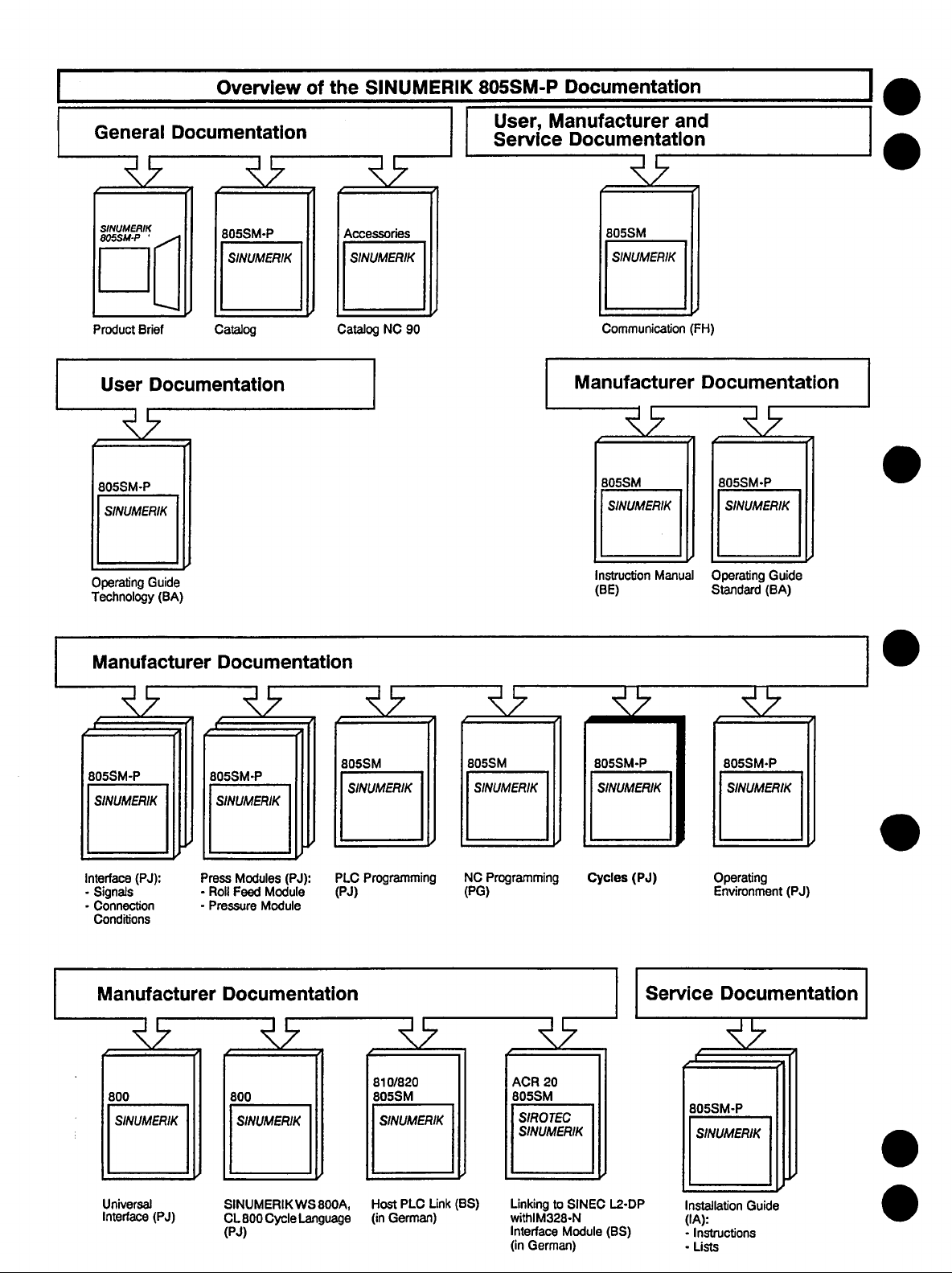
The documentation of the SINUMERIK 805SM-P is subdivided into 4 parts:
l
General Documentation
l
User Documentation
l
Manufacturer Documentation and
l
Service Documentation
The following manuals are part of the Manufacturer Documentation:
l
Instruction Manual
l
Interface Description Part
l
Interface Description Part 2: Connection Conditions
l
PLC Programming Guide
l
Standard Operating Guide
l
NC Programming Guide
l
Roll Feed Module, Planning Guide
l
Pressure Control Module, Planning Guide
l
Cycles, Planning Guide
1:
Signals
This documentation (Cycles, Planning Guide) is intended for the press manufacturer and describes
the start-up of the standard cycles.
This manual is written for technically qualified personnel, especially those having knowledge of or
being trained in automation and control technology.
The knowledge, understanding and correct observance of all the Safety Rules and Warnings are the
necessary preconditions for the safe installation and commissioning as well as for the safe operation
and maintenance of the product described in this manual. This manual describes the General Safety
Rules and Warnings. Only the qualified personnel has the necessary technical knowledge to
properly interpret and apply all the Safety Rules and Warnings in a particular case.
The contents of this instruction manual shall not become part or modify any prior or existing
agreement, commitment or relationship. The Sales Contract between the parties is the sole warranty
of Siemens. Any statements contained herein do not create new warranties or modify the existing
warranty.
If you need further documentation for the SINUMERIK 805SM-P, please contact your local Siemens
representative.
Page 6
-
0
General Remarks
Press Data
Central R Parameters
Channel-Specific R Parameters
Overview of the Data Exchange
Within the Control
1
u
4 .
q
5
rl
.o
Fixed Cycles
Basic Press Functions
Tool Change
Messages of the Standard Cycles
6
cl
7
tl
9
I I
Annex
10
cl
Page 7
Contents
Page
1 General Remarks . . . . . , . . . . . . . . . . . . . . . . . . . . . . . . . . . . . . . .
2
3 Central R Parameters . . . . . . . . . . . , . . , . . . . , . . . . . . . . . . . . . . .
3.1 General remarks
3.2 R parameter range R800 - R899
3.3 R parameter range R900 - R984
3.4 R parameter range R985 - R999
3.5 Work memory / R parameter range RlOOO - R1499
3.6 Input buffer / R parameter range R1500
3.7 Tool data memory / R parameter range R2000 - Rl9999
4 Channel-Specific R Parameters
4.1
4.2
5 Overview of the Data Exchange Within the Control . . . . . . . s . . . .
Press Data ..,................,..,....................
....................................... 3-l
............................
............................ 3-l
............................ 3-l
. . . , . . . . . . . . . . . . . . . . . . . . , . .
Local parameters R50 - R99
Transfer parameters RO - R49
...............................
.............................. 4-l
. R1999
............... 3-2
................. 3-2
...........
l-l
2-l
3-l
3-l
3-2
4-l
4-l
5-1
6 Fixed Cycles . . . . . . . . . . . . . . . . . , . . . . . . , . . . . . . . . . . . . . . . .
6.1 Continuous stroke
6.1 .l Description
6.1.2 Start-up checklist
6.1.3 Flowchart
6.2 Single stroke
6.2.1 Description
6.2.2 Start-up checklist
6.2.3 Flowchart
6.3 Set up - Main drive JOG-INC mode
6.3.1
6.3.2
6.3.3 Flowchart
6.4 Common subroutines
6.4.1 TDC following L994
6.4.2 Correction of all tool change axes L995
6.4.3 Calculation of the brake angle L 998
Description
Start-up checklist
...........................................
............................................
...........................................
............................................
............................................
......................................
.......................................
..........................................
.......................................
..........................
...........................................
.......................................
....................................
.....................................
.......................
.........................
6-1
6-l
6-l
6-2
6-4
6-7
6-7
6-8
6-l 0
6-l 3
6-l 3
6-14
6-l 6
6-l 9
6-l 9
6-20
6-21
Page 8
7
Basic Press Functions
. . . . . . . . . . . . . . . . . . . . . . . . . . . . . . . . . .
7-l
7.1
7.1.1
7.1.2
7.1.3
7.1.4
7.2
7.2.1
7.2.2
7.2.3
7.2.4
7.3
7.3.1
7.3.2
7.3.3
7.4
7.4.1
7.4.2
7.4.3
8
8.1
8.1.1
8.1.2
8.2
8.2.1
8.2.2
8.3
8.3.1
8.3.2
8.3.3
8.3.4
8.4
Safety stroke
Description
Start-up checklist
CodesforthePLC
Flowchart
..........................................
...........................................
.......................................
......................................
.............................................
Reversing ............................................
Description
Start-up checklist
CodesforthePLC
...........................................
.......................................
......................................
Flowchart .............................................
Open press
Description
CodesforthePLC
Flowchart
Close press
Description
Codesforthe PLC
...........................................
...........................................
......................................
.............................................
...........................................
...........................................
......................................
Flowchart .............................................
Tool Change ..,.....,.....,...........................
General remarks
Description
........................................
...........................................
Flowchart .............................................
Manual tool change - jog main drive (L9)
Description
Flowchart
Automatic tool change (L8)
Description
...........................................
.............................................
................................
...........................................
......................
Example for the implementation of an automatic tool change
Automatic stroke adjustment during the tool change
...............
Flowchart .............................................
Description of the step cycles
..............................
........
7-l
7-l
7-l
7-l
7-2
7-4
7-4
7-4
7-4
7-5
7-7
7-7
7-7
7-7
7-8
7-8
7-8
7-8
8-l
8-l
8-l
8-2
8-6
8-6
8-7
8-8
8-8
8-8
8-9
8-11
8-12
9
9.1
9.2
9.3
9.4
9.5
9.6
9.7
9.8
9.8.1
9.8.2
9.9
Messages of the Standard Cycles
CONTINUOUS STROKE cycle
SINGLE STROKE cycle
TOOL CHANGE cycle
REVERSING cycle
....................................
......................................
SAFETY STROKE cycle
CLOSE PRESScycle
OPEN PRESScycle
....................................
.....................................
..............................
..................................
..................................
GENERAL TOOL CHANGE cycle
MANUAL TOOL CHANGE
AUTOMATIC TOOL CHANGE
Step cycles
...........................................
.................................
..............................
. . . . . . . . . . . . . . . . . . . . . . . . .
............................
9-l
9-l
9-4
9-6
9-9
9-l 0
9-11
9-11
9-12
9-13
9-14
9-14
Page 9
10 Annex .,....,........................................
lo-l
10.1
10.1.1
10.1.2
10.1.3
10.2
10.3
10.3.1
10.3.2
10.3.3
10.4
10.5
10.6
Overview of the standard cycles
Technology cycles
......................................
Subroutines for the technology cycles
Step cycles
...........................................
Overview of the work memory
Survey of the R parameters used
Local R parameters
Transfer parameters
Central R parameters
(MO
- R99)
(RO - R49)
....................................
............................
........................
..............................
...........................
............................
.............................
Survey of the @ commands used in the standard cycles
Overview of all cycle-specific machine data
Flag area assigned to standard cycles
....................
........................
...........
10-l
10-l
10-l
10-2
103
10-9
1 o-9
10-11
10-12
10-14
10-15
lo-18
Page 10
06.93
1 General Remarks
General Remarks
Cycles are subroutines which can be stored either in the part program memory or (from software version 2.0 onwards) in the user memory submodule of the control. With these subroutines the technology modes of the press are implemented (continuous stroke, single stroke,
etc.). Furthermore, a (TOOL CHANGE) cycle is necessary for carrying out a tool change.
A subroutine consists of the following program sections:
. ENTRY SECTION
. LOOP SECTION
. TERMINATING SECTION
In the ENTRY SECTION, the starting conditions are checked on start-up of an operating mode.
If a starting condition is not fulfilled, a corresponding “CYCLE MESSAGE” is issued and the
cycle interrupted. These messages also provide hints for the user. Information on the causes
and, if necessary, about a remedy may be found in the Technology Operating Guide and
the Installation Instructions.
After the ENTRY SECTION the program jumps into the LOOP SECTION, which coordinates
the press operating mode and provides press-specific functions (see the general overview of
the data exchange within the control). Only after a cycle stop has been triggered is this loop
section left and the TERMINATING SECTION processed, so that the operating mode and with
it the subroutine are terminated in a defined state.
The flowcharts describe the program flow of the technology cycles in detail.
Apart from the technology cycles there are several further subroutines (L 900 - L 999), which
are mainly calculating programs.
The step cycles provide certain functions which are necessary for the tool change procedure.
Thus the sequence of operations for the tool change may be adapted “individually”to the
press.
Exchange of information with the PLC is carried out via:
Inputs (commands for reading and writing)
l
. outputs
l
Flags (flag interface of the standard cycles, overview in Chapter
l
R parameters (FE 61/62).
10,
Annex)
Exchange of information with the NC is carried out via:
l
Press data (via @ commands, see installation lists)
l
Central R parameters (R965-R999)
The selection of the press operating modes (corresponding menu + subroutine) is carried out
via the operator interface. The subroutine number belonging to the operating mode is preselected automatically.
The I/O fields of the individual operating modes are only updated after the NC-start.
For almost every press operating mode a so-called cycle is necessary. A cycle is a background program of a loop.
@ Siemens AG 1991 All Rights Reserved 6285 440.ONX02-OAAl
SINUMERIK 805SM-P (PJ)
l-l
Page 11
1 General Remarks
06.93
Loading of standard cycles:
The cycles are supplied on a floppy disk formatted in MS-DOS. The different language ver-
sions are stored in the following sub-directories:
805SMP-D... German
805SMP-E... English
805SMP-I . . . Italian
805SMP,S... Spanish
805SMP-F . . . French
The cycles on the floppy disks are available in CL 800 source code (extension: ZPQ) and in
DIN code (extension: ZPL).
Information about the loading of the cycles can also be found in the README.TXT file available on the floppy disk.
For the transfer to the control there are the following possibilities:
a) Selection of the batch file: “INSTALLBAT
Procedure:
1) Connect the transfer cable (Order No.: 6FC9 344-4Rn) to COMl.
2.) Preselect and initialize (FITS-Line, 9600 Bd) the correct interface at the control and
start it for input.
3.) Call up the batch file from the corresponding floppy disk drive and state the desired
language version.
Example:
AUNSTALL E and press Enter .
cl
+ The English language version is transferred from the floppy disk in disk drive A to
COMl. At the same time, the programmer interface is initialized correctly.
b) Transfer of the standard cycles with the MS-DOS system command COPY (the batch file
described above uses the same command):
Please make sure that the programmer interface is initialized correctly (7 data bits, 2 stop
bits, parity = even).
Example:
COPY A:U05SMPJV.ZPL COMl
c) With the program PCIN, version 2.0, the transfer may be carried out comfortably in both
directions (PG-NC).
It is a menu-driven program which offers the possibility to configure the interfaces
accordingly.
All files with the extension “ZPL” have to be transferred from the sub-directory for the
desired language version (see above).
d) If a workstation (WSSOOA) is available, it can be used for the transfer. The standard cycles
have been created with this software package. Transfer the files from the floppy disk.
l-2
CJ Siemens AG 1991 All Rights Reserved 6265 440-ONX02-OAAl
SINUMERIK 805S.WP (PJ)
Page 12
12.91 2 Press Data
2
This data area can be accessed from the cycle via @-commands.
Press Data
e rndwdual data
INSTRUCTIONS.
and for the access
possibilities,
@ Siemens AG 1991 All Rights Reserved 6285 440.ONX02-OAAl
SINUMERIK 605SM.P (PJ)
2-1
Page 13
06.93
3 Central R Parameters
3.1 General remarks
3
Central R Parameters
3.1 General remarks
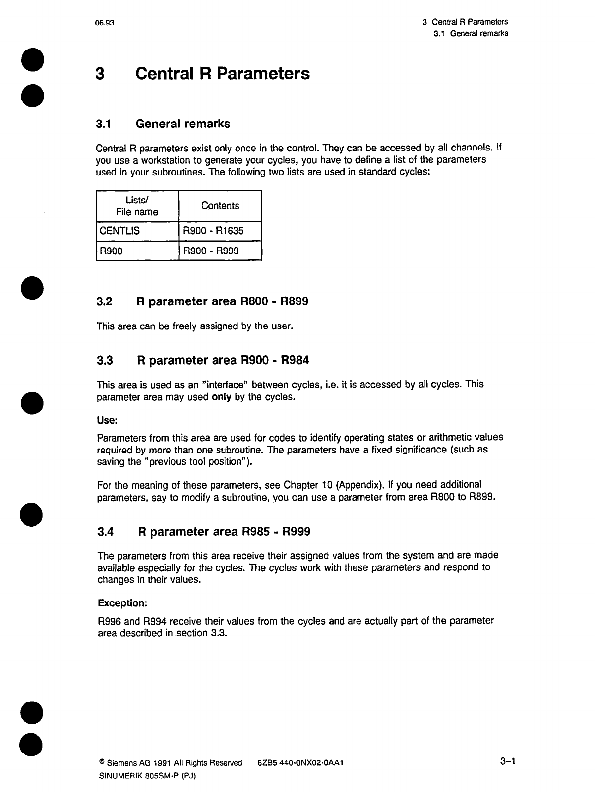
Central R parameters exist only once in the control. They can be accessed by all channels. If
you use a workstation to generate your cycles, you have to define a list of the parameters
used in your subroutines. The following two lists are used in standard cycles:
Lists/
File name
Contents
I
3.2 R parameter area R800 - R899
This area can be freely assigned by the user.
3.3 R parameter area R900 - R984
This area is used as an “interface” between cycles, i.e. it is accessed by all cycles. This
parameter area may used only by the cycles.
Use:
Parameters from this area are used for codes to identify operating states or arithmetic values
required by more than one subroutine. The parameters have a fixed significance (such as
saving the “previous tool position”).
For the meaning of these parameters, see Chapter
parameters, say to modify a subroutine, you can use a parameter from area R800 to R899.
3.4
The parameters from this area receive their assigned values from the system and are made
available especially for the cycles. The cycles work with these parameters and respond to
changes in their values.
Exception:
R996 and R994 receive their values from the cycles and are actually part of the parameter
area described in section 3.3.
R parameter area R985 - R999
10
(Appendix). If you need additional
@ Siemens AG 1991 All Rights Reserved
SINUMERIK 805SMaP (PJ)
6tB5 440.ONX02-OAAl
3-l
Page 14
3 Central R Parameters
3.5 Work memory I R parameter area RlOOO - R1499
06.93
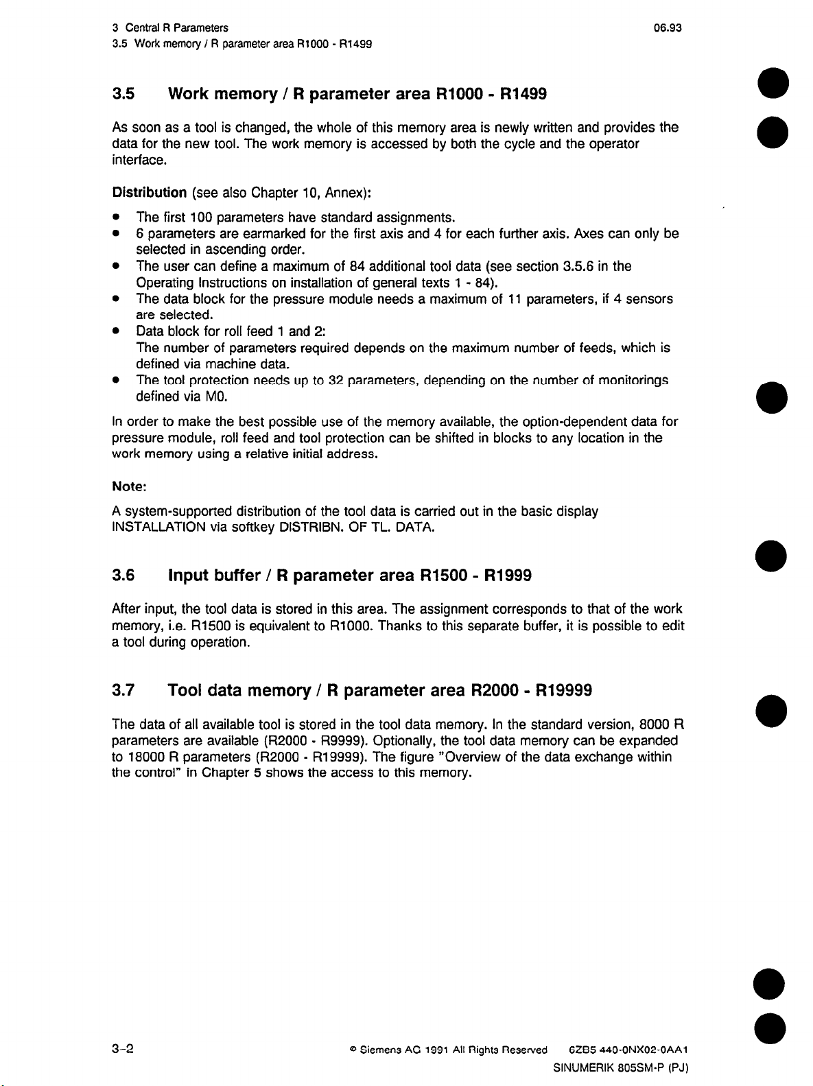
3.5 Work memory / R parameter area RlOOO - R1499
As soon as a tool is changed, the whole of this memory area is newly written and provides the
data for the new tool. The work memory is accessed by both the cycle and the operator
interface.
Distribution
The first 100 parameters have standard assignments.
6 parameters are earmarked for the first axis and 4 for each further axis. Axes can only be
selected in ascending order.
The user can define a maximum of 84 additional tool data (see section 3.56 in the
Operating Instructions on installation of general texts 1 - 84).
The data block for the pressure module needs a maximum of 11 parameters, if 4 sensors
are selected.
Data block for roll feed 1 and 2:
The number of parameters required depends on the maximum number of feeds, which is
defined via machine data.
The tool protection needs up to 32 parameters, depending on the number of monitorings
defined via MO.
In order to make the best possible use of the memory available, the option-dependent data for
pressure module, roll feed and tool protection can be shifted in blocks to any location in the
work memory using a relative initial address.
(see also Chapter 10, Annex):
Note:
A system-supported distribution of the tool data is carried out in the basic display
INSTALLATION via softkey DISTRIBN. OF TL. DATA.
3.6 Input buffer / R parameter area R1500 - R1999
After input, the tool data is stored in this area. The assignment corresponds to that of the work
memory, i.e. R1500 is equivalent to RlOOO. Thanks to this separate buffer, it is possible to edit
a tool during operation.
3.7
The data of all available tool is stored in the tool data memory. In the standard version, 8000 R
parameters are available (R2000 - R9999). Optionally, the tool data memory can be expanded
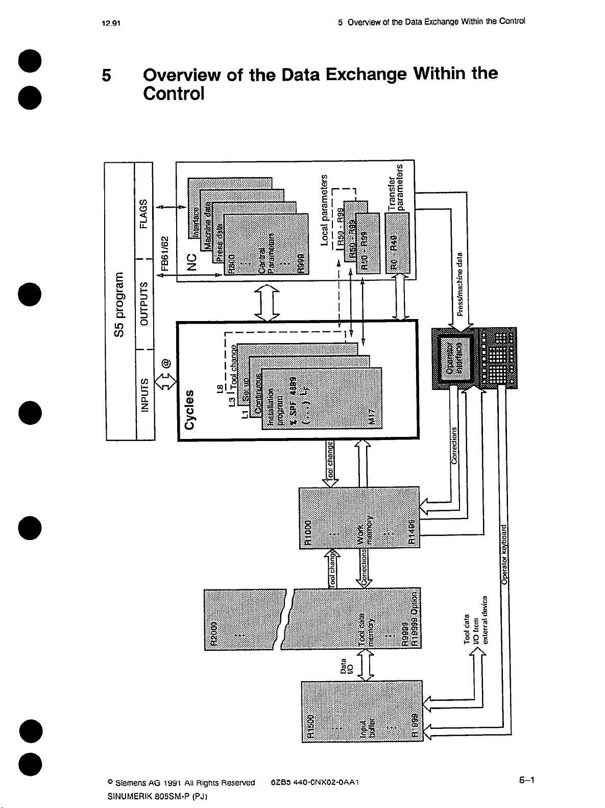
to 18000 R parameters (R2000 - R19999). The figure “Overview of the data exchange within
the control” in Chapter 5 shows the access to this memory.
Tool data memory / R parameter area R2000 - R19999
3-2
8 Siemens AG 1991 All Rights Reserved 6265 440.ONX02-OAAl
SINUMERIK 805SM.P (PJ)
Page 15
12.91
4 Channel-Specific R
4.1 Local parameters I350 - R99
Parameters
4 Channel-Specific R Parameters
4.1 Local parameters R50 - R99
Local R parameters are used as a “scratchpad” for calculations and are only valid for one
cycle. As soon as the program level is left by calling a subroutine, the local variables are saved
and preset to “zero” for the following program. Therefore, they can be used as independent
parameters in the program called.
The following two data formats can be defined in the cycle for these parameters:
Local Integer: In this format, the variables can only be integers.
Value range: *I- 99999999
Local Real: In this format, the variables are defined as floating-point numbers.
Value range: + I- 0.00000001 to + I- 99999999.
4.2 Transfer parameters RO - R49
These R parameters have the same significance in all cycles within one NC channel. I.e., the
value of the variable is preserved on branching into a subroutine; the value is, in a way,
transferred.
Definition in the cycle:
Par Real: Transfer parameter as a floating-point number.
Value range: +/- 0.00000001 to +/- 99999999.
An overview of the parameters used in the standard cycles is given in Chapter 10, Annex.
0 Siemens AG 1991 All Rights Resewed 6285 440.ONX02-OAAl
SINUMERIK 605SM-P (PJ)
4-l
Page 16
12.91
5 Overview of the Data Exchange Within the Control
5 Overview of the Data Exchange Within the
Control
I I
l-----------
V
@ Siemens AG 1991 All Rights Reserved
SINUMERIK 805SM-P (PJ)
6ZB5 440.ONX02-OAAl
Page 17
12.91 6 Fixed cycles
6.1 Continuous stroke
6
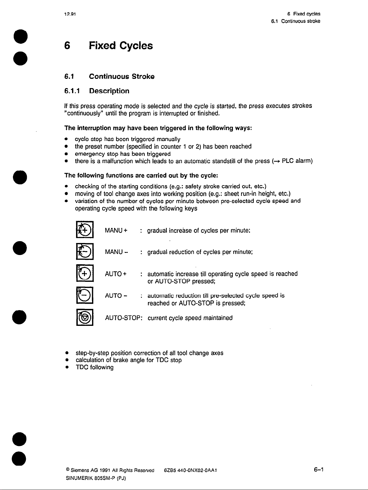
6.1 Continuous Stroke
6.1.1 Description
If this press operating mode is selected and the cycle is started, the press executes strokes
“continuously” until the program is interrupted or finished.
The interruption may have been triggered in the following ways:
l
l
l
l
The following functions are carried out by the cycle:
l
l
l
Fixed Cycles
cycle stop has been triggered manually
the preset number (specified in counter 1 or 2) has been reached
emergency stop has been triggered
there is a malfunction which leads to an automatic standstill of the press (+ PLC alarm)
checking of the starting conditions (e.g.: safety stroke carried out, etc.)
moving of tool change axes into working position (e.g.: sheet run-in height, etc.)
variation of the number of cycles per minute between preselected cycle speed and
operating cycle speed with the following keys
+
MANU+ : gradual increase of cycles per minute;
•l
El
MANU- : gradual reduction of cycles per minute;
+
la
la
AUTO+ : automatic increase till operating cycle speed is reached
or AUTO-STOP pressed;
AUTO- : automatic reduction till preselected cycle speed is
reached or AUTO-STOP is pressed:
AUTO-STOP: current cycle speed maintained
Ia
a
step-by-step position correction of all tool change axes
l
calculation of brake angle for TDC stop
l
TDC following
@ Siemens AG 1991 All Rights Reserved
SINUMERIK r305SM-P (PJ)
628.5 440.ONX02-OAA7
6-1
Page 18
6 Fixed Cycles
6.1.2 Start-up checklist
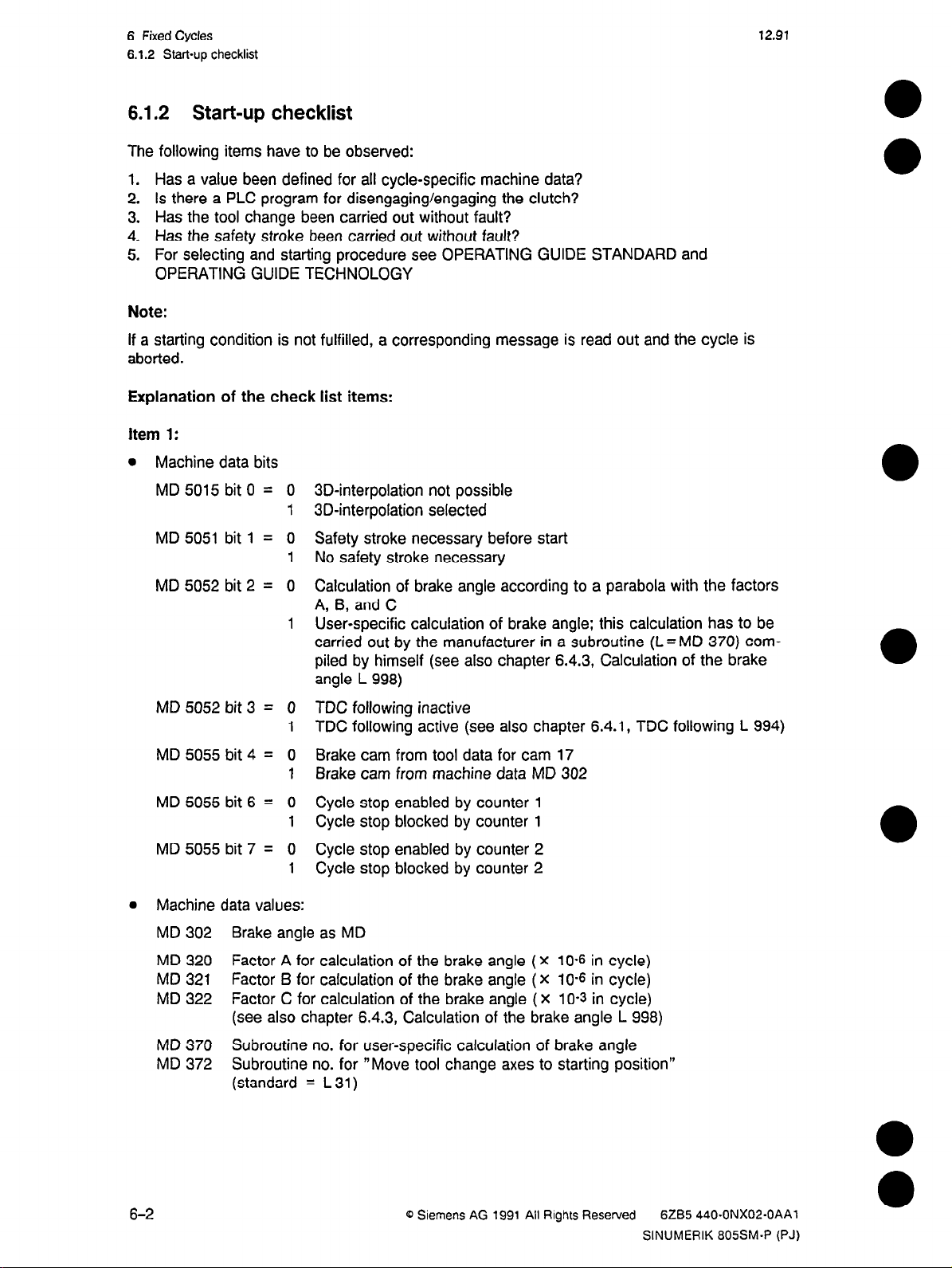
6.1.2 Start-up checklist
The following items have to be observed:
1. Has a value been defined for all cycle-specific machine data?
2. Is there a PLC program for disengaging/engaging the clutch?
3. Has the tool change been carried out without fault?
4. Has the safety stroke been carried out without fault?
5. For selecting and starting procedure see OPERATING GUIDE STANDARD and
OPERATING GUIDE TECHNOLOGY
Note:
If a starting condition is not fulfilled, a corresponding message is read out and the cycle is
aborted.
Explanation of the check list items:
Item 1:
l
Machine data bits
12.91
MD 5015 bit 0 = 0
1
MD 5051 bit 1 = 0
1
MD 5052 bit 2 = 0
1
MD 5052 bit 3 = 0
1
MD 5055 bit 4 = 0
1
MD 5055 bit 6 = 0
1
MD 5055 bit 7 = 0
1
l
Machine data values:
MD 302 Brake angle as MD
3D-interpolation not possible
3D-interpolation selected
Safety stroke necessary before start
No safety stroke necessary
Calculation of brake angle according to a parabola with the factors
A, 6, and C
User-specific calculation of brake angle; this calculation has to be
carried out by the manufacturer in a subroutine (L=MD 370) compiled by himself (see also chapter 6.4.3, Calculation of the brake
angle L 998)
TDC following inactive
TDC following active (see also chapter 6.4.1, TDC following L 994)
Brake cam from tool data for cam 17
Brake cam from machine data MD 302
Cycle stop enabled by counter 1
Cycle stop blocked by counter 1
Cycle stop enabled by counter 2
Cycle stop blocked by counter 2
MD 320 Factor A for calculation of the brake angle (X
10-E
in cycle)
MD 321 Factor B for calculation of the brake angle ( X 10-e in cycle)
MD 322 Factor C for calculation of the brake angle ( x 10-s in cycle)
(see also chapter 6.4.3, Calculation of the brake angle L 998)
MD 370 Subroutine no. for user-specific calculation of brake angle
MD 372 Subroutine no. for “Move tool change axes to starting position”
(standard = L 31)
6-2
0 Siemens AG 1991 All Rights Reserved 6285 440.ONX02-OAAl
SINUMERIK 805SM-P (PJ)
Page 19
12.91
6 Fixed Cycles
6.1.2 Start-up checklist
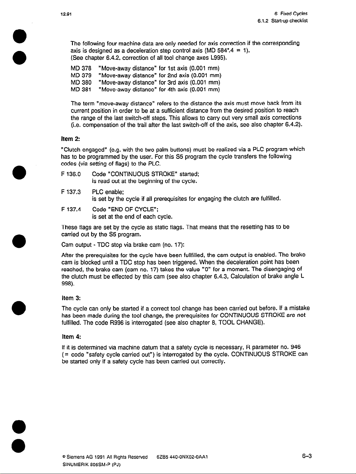
The following four machine data are only needed for axis correction if the corresponding
axis is designed as a deceleration step control axis (MD 584*.4 = 1).
(See chapter 6.4.2, correction of all tool change axes L995).
MD 378 “Move-away distance” for 1st axis (0.001 mm)
MD 379 “Move-away distance” for 2nd axis (0.001 mm)
MD 380 “Move-away distance” for 3rd axis (0.001 mm)
MD 381 “Move-away distance” for 4th axis (0.001 mm)
The term “move-away distance” refers to the distance the axis must move back from its
current position in order to be at a sufficient distance from the desired position to reach
the range of the last switch-off steps. This allows to carry out very small axis corrections
(i.e. compensation of the trail after the last switch-off of the axis, see also chapter 6.4.2).
Item 2:
“Clutch engaged” (e.g. with the two palm buttons) must be realized via a PLC program which
has to be programmed by the user. For this S5 program the cycle transfers the following
codes (via setting of flags) to the PLC.
F 136.0 Code “CONTINUOUS STROKE” started;
is read out at the beginning of the cycle.
F 137.3 PLC enable:
is set by the cycle if all prerequisites for engaging the clutch are fulfilled.
F 137.4
Code “END OF CYCLE”:
is set at the end of each cycle.
These flags are set by the cycle as static flags. That means that the resetting has to be
carried out by the 5% program.
Cam output - TDC stop via brake cam (no. 17):
After the prerequisites for the cycle have been fullfilled, the cam output is enabled. The brake
cam is blocked until a TDC stop has been triggered. When the deceleration point has been
reached, the brake cam (cam no. 17) takes the value “0” for a moment. The disengaging of
the clutch must be effected by this cam (see also chapter 6.4.3, Calculation of brake angle L
998).
Item 3:
The cycle can only be started if a correct tool change has been carried out before. If a mistake
has been made during the tool change, the prerequisites for CONTINUOUS STROKE are not
fulfilled. The code R996 is interrogated (see also chapter 8, TOOL CHANGE).
item 4:
If it is determined via machine datum that a safety cycle is necessary, R parameter no. 946
code “safety cycle carried out”) is interrogated by the cycle. CONTINUOUS STROKE can
(=
be started only if a safety cycle has been carried out correctly.
0 Siemens AG 1991 All Rights Reserved
SINUMERIK 805SM-P (PJ)
6285 440.ONX02-OAAl
6-3
Page 20
6 Fixed Cycles
6.1.3 Flowchart
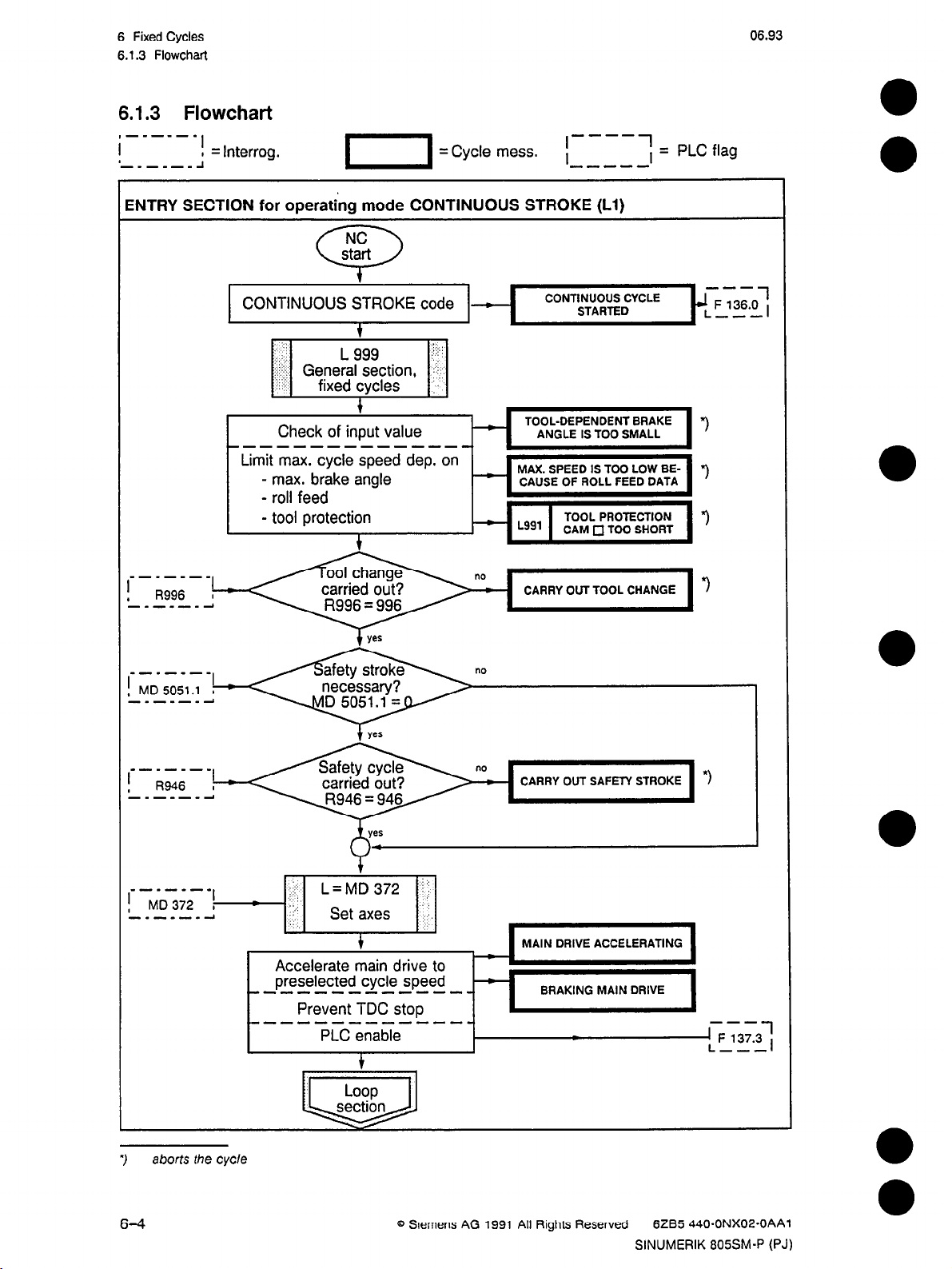
6.1.3 Flowchart
,-----.
I
1
-_-_-_ J
iNTRY SECTION for operating mode CONTINUOUS STROKE (Ll)
I
I = Interfog.
06.93
.-_-_-_
CONTINUOUS STROKE code -
.,
‘:
:,I
::.‘j;:: General section, <I, :
.: ,.’
,.
:-
---------------
Check of input value
Lggg .!.‘!i
fixed cycles :,
Limit max. cycle speed dep. on
- max. brake angle
- roll feed
- tool protection
CONTINUOUS CYCLE
STARTED
TOOL-DEPENDENT BRAKE “)
ANGLE IS TOO SMALL
- MAX. SPEED IS TOO LOW BECAUSE OF ROLL FEED DATA
CARRY OUT TOOL CHANGE
---
JLF 136.0
---
*)
1
,
.------
aborts the cycle
3
6-4
Accelerate main
preselected cycle speed
w------------m
--------------
Prevent TDC stop
PLC enable
CARRY OUT SAFETY STROKE
MAIN DRIVE ACCELERATING
drive to
-
Q Slemens AG 1991 All Rights Reserved
BRAKING MAIN DRIVE
/
“1
---
1 F 137.3
L ---
6285 440-ONXOZ-OAAl
SINUMERIK 805SM-P (PJ)
1
,
Page 21
12.91 6 Fixed Cydes
6.13 Flowchart
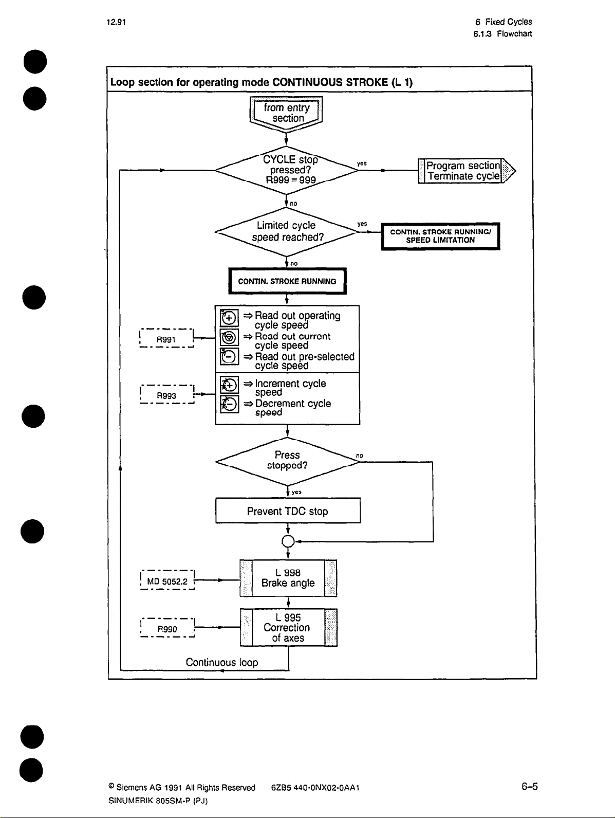
.oop section for operating mode CONTINUOUS STROKE (L 1)
from entry
section
0
I
, R991 I ?
---*---I
-mm----
l
,
R993 I 7
--m----1
no
1
CONTIN. ST*; ~~UNNINO 1
+ + Read out operating
Dl
EBI
Dl
la
IBI
cycle speed
3 Read out current
cycle speed
- 3 Read out pre-selected
cycle speed
+ * Increment cycle
speed
+ Decrement cycle
speed
I
i Terminate
CONTIN. STROKE RUNNING/
SPEED LIMITATION
cycle
section i: Program
@ Siemens AG 1991 All Rights Reserved
SINUMERIK 805SM.P (PJ)
yes
t
Prevent TDC stop
6ZB5 440.ONX02-OAAl
6-5
Page 22
6 Fixed Cycles
6.1.3 Flowchart
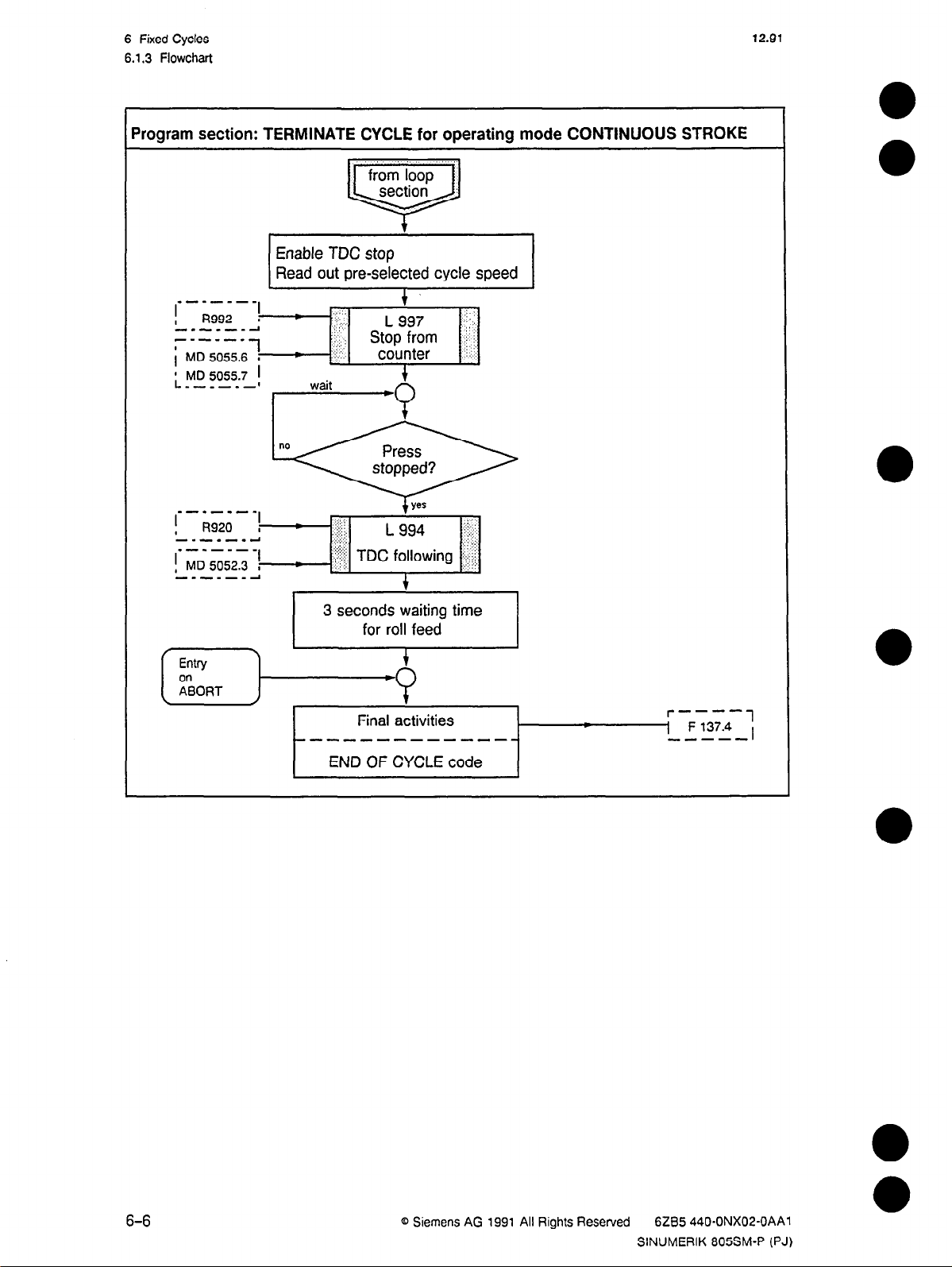
‘rogram section: TERMINATE CYCLE for operating mode CONTINUOUS STROKE
Enable TDC stop
Read out pre-selected cycle speed
12.91
Final activities
we-------m--v-
END OF CYCLE code
r----
1 F 137.4
----a
1
,
6-6
@ Siemens AG 1991 All Rights Reserved
6ZB5 440.ONX02-OAAl
SINUMERIK 805SM-P (PJ)
Page 23
12.91
6.2 Single stroke
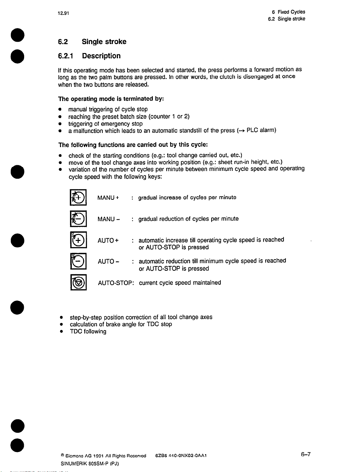
6.2.1 Description
If this operating mode has been selected and started, the press performs a forward motion as
long as the two palm buttons are pressed. In other words, the clutch is disengaged at once
when the two buttons are released.
The operating mode is terminated by:
l
manual triggering of cycle stop
l
reaching the preset batch size (counter 1 or 2)
l
triggering of emergency stop
l
a malfunction which leads to an automatic standstill of the press (+ PLC alarm)
The following functions are carried out by this cycle:
l
check of the starting conditions (e.g.: tool change carried out, etc.)
l
move of the tool change axes into working position (e.g.: sheet run-in height, etc.)
l
variation of the number of cycles per minute between minimum cycle speed and operating
cycle speed with the following keys:
6 Fixed Cycles
6.2 Single stroke
+
MANU+ :
gradual increase of cycles per minute
Dl
MANU- :
gradual reduction of cycles per minute
Ial
+
Dl
la
AUTO+ :
AUTO- :
AUTO-STOP:
automatic increase till operating cycle speed is reached
or AUTO-STOP is pressed
automatic reduction till minimum cycle speed is reached
or AUTO-STOP is pressed
current cycle speed maintained
la
l
step-by-step position correction of all tool change axes
l
calculation of brake angle for TDC stop
l
TDC following
0 Siemens AG 1991 All Rights Reserved
SINUMERIK 805SM-P (PJ)
6285 440.ONX02-OAAl
6-7
Page 24
6 Fixed Cycles
6.2.2 Start-up checklist
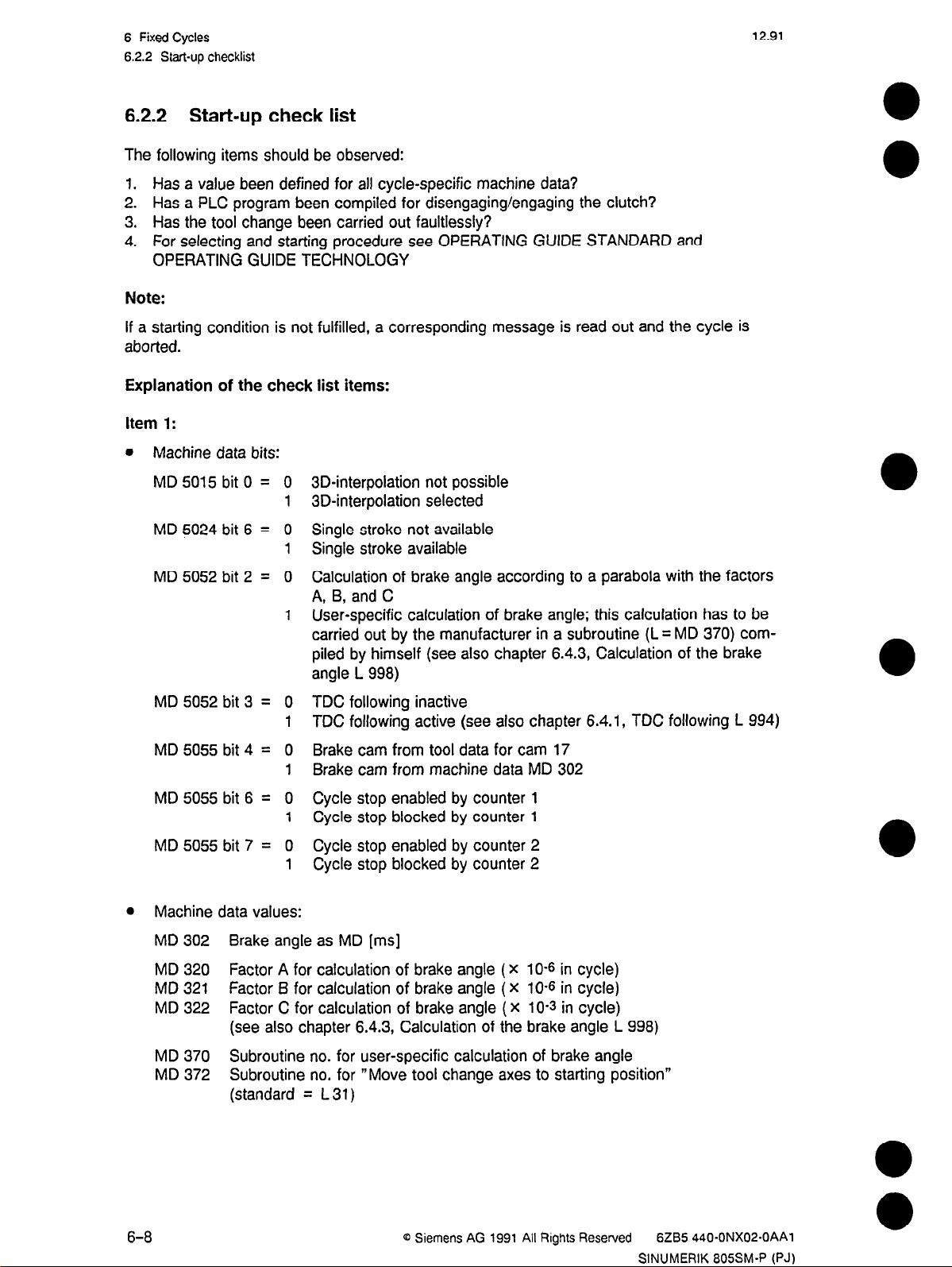
6.2.2 Start-up check list
The following items should be observed:
1. Has a value been defined for all cycle-specific machine data?
2. Has a PLC program been compiled for disengaging/engaging the clutch?
3. Has the tool change been carried out faultlessly?
4. For selecting and starting procedure see OPERATING GUIDE STANDARD and
OPERATING GUIDE TECHNOLOGY
Note:
If a starting condition is not fulfilled, a corresponding message is read out and the cycle is
aborted.
Explanation of the check list items:
Item 1:
l
Machine data bits:
12.91
MD 5015 bit 0 = 0
MD 5024 bit 6 = 0
3D-interpolation not possible
1
3D-interpolation selected
Single stroke not available
Single stroke available
MD 5052 bit 2 = 0
Calculation of brake angle according to a parabola with the factors
A, 6, and C
User-specific calculation of brake angle; this calculation has to be
carried out by the manufacturer in a subroutine (L = MD 370) com-
piled by himself (see also chapter 6.4.3, Calculation of the brake
angle L 998)
MD 5052 bit 3 = 0
MD 5055 bit 4 = 0
MD 5055 bit 6 = 0
MD 5055 bit 7 = 0
l
Machine data values:
TDC following inactive
1
TDC following active (see also chapter 6.4.1, TDC following L 994)
Brake cam from tool data for cam 17
1
Brake cam from machine data MD 302
Cycle stop enabled by counter 1
1
Cycle stop blocked by counter 1
Cycle stop enabled by counter 2
1
Cycle stop blocked by counter 2
MD 302 Brake angle as MD [ms]
MD 320 Factor A for calculation of brake angle
(X
10-s in cycle)
MD 321 Factor B for calculation of brake angle ( X 10-s in cycle)
MD 322 Factor C for calculation of brake angle (X 10-s in cycle)
(see also chapter 6.4.3, Calculation of the brake angle L 998)
MD 370 Subroutine no. for user-specific calculation of brake angle
MD 372 Subroutine no. for “Move tool change axes to starting position”
(standard = L 31)
6-8
0 Siemens AG 1991 All Rights Reserved
6285 440.ONX02-OAAl
SINUMERIK 805SM-P (PJ)
Page 25
12.91
6 Fixed Cycles
6.2.2 Start-up checklist
The following four machine data are only needed for axis correction if the corresponding
axis is designed as a deceleration step control axis (MD 584’.4 = 1). (See chapter 6.42,
Correction of all tool change axes).
MD 378 “Move-away distance” for 1st axis (0.001 mm)
MD 379
“Move-away distance” for 2nd axis (0.001 mm)
MD 380 “Move-away distance” for 3rd axis (0.001 mm)
MD 381 “Move-away distance” for 4th axis (0.001 mm)
The term “move-away distance” refers to the distance the axis must move back from its
current position in order to be at a sufficient distance from the desired target position to
reach the range of the last switch-off steps. This allows to carry out very small axis
corrections (i.e. compensation of the trail after the last switch-off of the axis, see also
chapter 6.4.2).
Item 2:
“Clutch engaged” (e.g. with the two palm buttons) has to be realized via a PLC program,
which has to be programmed by the user. For this %-program the cycle transfers the following
codes (via setting of flags) to the PLC.
F 136.1
Code “SINGLE STROKE” started:
is read out at the beginning of the cycle.
F 137.3 PLC enable:
is set by the cycle if all prerequisites for engaging the clutch are fulfilled.
F 137.4 “END OF CYCLE” code;
is set at the end of each cycle.
These flags are set by the cycle as static flags. That means that the resetting has to be
carried out by the 55 program.
Cam output - TDC stop via brake cam (no. 17):
After the prerequisites for the cycle have been fullfilled, the cam output is enabled. The brake
cam is always enabled during this cycle, i.e. during every stroke the brake cam (no. 17) takes
the value “0” for a moment when the deceleration point is reached. The disengaging of the
clutch must be effected by this cam (see also chapter 6.4.3, Calculation of brake angle L 998).
Item 3:
The cycle can only then be started if a correct tool change has been carried out before. If a
fault has ocurred during the tool change, the prerequisites for SET UP are not fulfilled. The
code R996 is interrogated (see also chapter 8, TOOL CHANGE).
@ Siemens AG 1991 All Rights Reserved 6ZB5 440*ONXO2-OAAl
SINUMERIK 805SM-P (PJ)
6-9
Page 26
6 Fixed Cycles
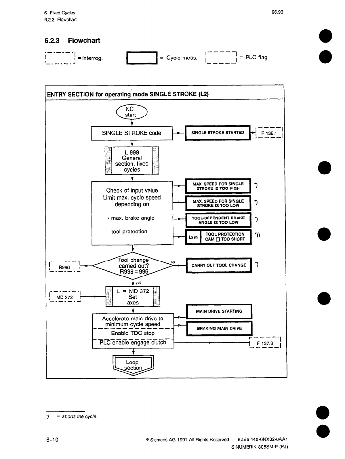
6.2.3 Flowchart
6.2.3 Flowchart
,---w-e
I
I
-,-.-.A
ENTRY SECTION for operating’tnode SINGLE STROKE (L2)
I
I = Interrog.
1 = Cycle mess. i
NC
start
0
t
SINGLE STROKE code
i
- SINGLE STROKE STARTED
06.93
,----7
;=
PLC flag
-I--
I
, F 136.1
----
Check of input value
Limit max. cycle speed
depending on
- max. brake angle
- tool protection
Accelerate main drive to
minimum cycle speed
-m-v-------Enable TDC stop
~~e~~e~<g~get~h-
MAX. SPEED FOR SINGLE
STROKE IS TOO HIGH
ANGLE IS TOO LOW
CAM 0 TOO SHORT
MAIN DRIVE STARTING
BRAKING MAIN DRIVE
r----i
1 F 137.3
-----
i
3
6-10
= aborts
the cycle
0 Siemens
AG 1991 All Rights Reserved 6ZB5 440-ONX02-OAAl
SINUMERIK 805SM-P (PJ)
Page 27
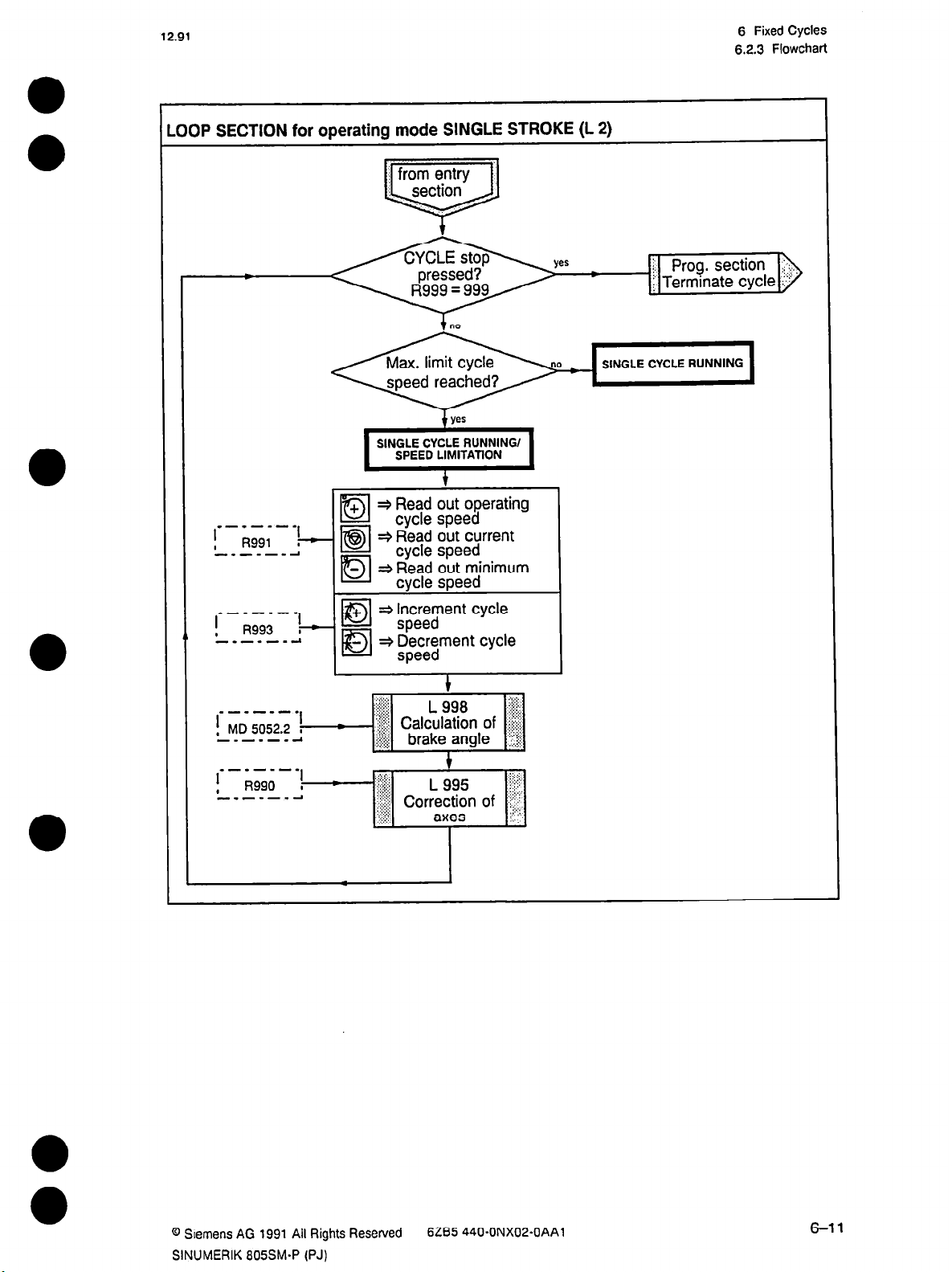
12.91
OOP SECTION for operating mode SINGLE STROKE (L 2)
SINGLE CYCLE RUNNING/
SPEED LIMITATION
#
=$ Read out operating
*-*em-.
I
, I?991
------A
la
cycle speed
~4 Read out current
cycle speed
* Read out minimum
cycle speed
* Increment cycle
speed
=+ Decrement cycle
speed
6 Fixed Cycles
6.2.3 Flowchart
SINGLE CYCLE RUNNING
------.
I
, MD 5052.2 I
------A
--.-mm*
I
,
R990
-.---.A
+
I
I
*
:;:::;.:
,:,q::
%$ Correction of ‘i.jr:i;
.,. :,.,j
,:>:::’
1
L 995
i fix;;
:‘,; >
axes iii’::
@ Slemens AG 1991 All Rights Resewed
SINUMERIK 805SM-P (PJ)
6285 440.ONX02-OAAl
6-11
Page 28
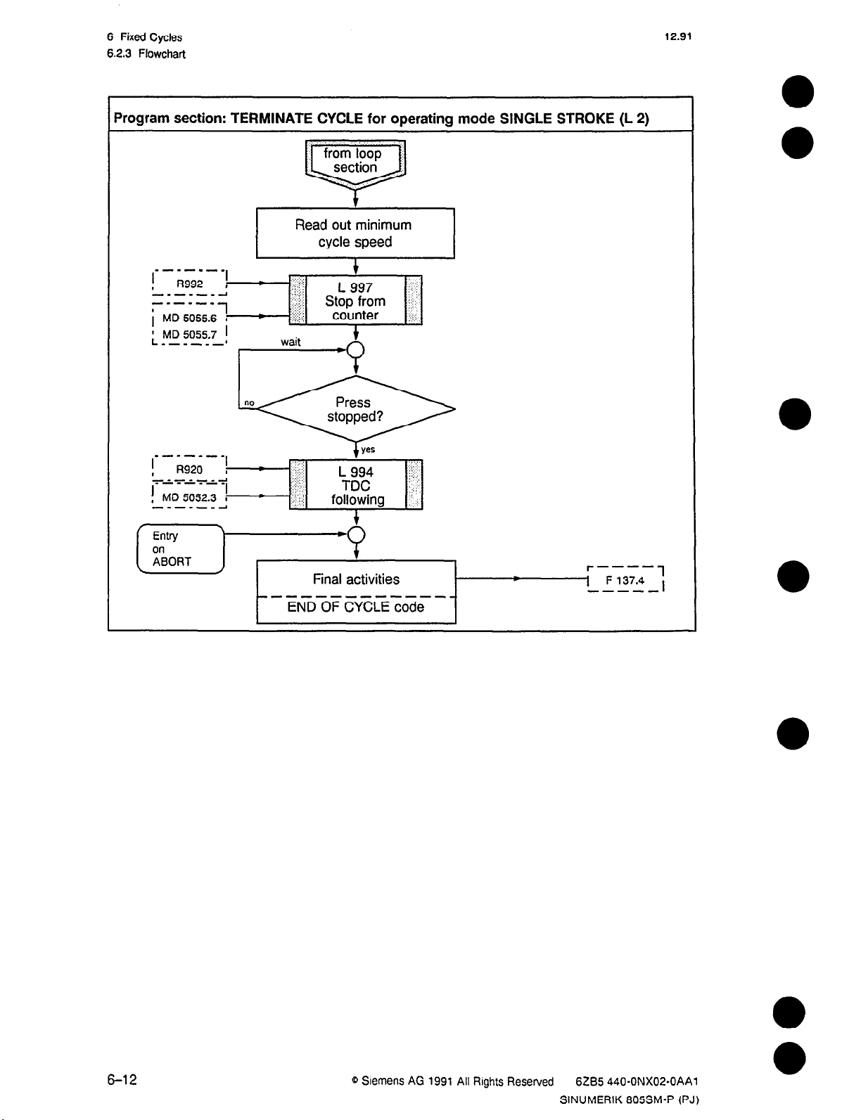
6 Fixed Cycles
62.3 Flowchart
Program section: TERMINATE CYCLE for operating mode SINGLE STROKE (L 2)
Read out minimum
cycle speed
12.91
m-.-.-s
I
, R992 ,
-.-e---1
---e-w
MD 5055.6 I
i
; MD 5055.7 1
----m-1
1
I
,
.‘:I :y:j
,::: :
‘;;,I; ,t;,9;;m ;jj.
..:,:j,
;j :)x;
wait
+
counter ::jj:,
1
-zivr = ;-FyLFj
-----------END OF CYCLE code
6-12
0 Slemens AG 1991 All Rights Reserved
6285 440.ONX02-OAAl
SINUMERIK 805SM-P (PJ)
Page 29
12.91
6.3 Set up - Main drive JOG-INC mode
6.3 Set up - Main drive JOG-INC mode
6.3.1 Description
If this operating mode has been selected and started, the press performs a stroke in forward
direction as long as the two palm buttons are pressed. When the buttons are released, the
clutch is disengaged at once, The eccentric may thus be jogged into any position over the
entire stroke length.
There are two different operating modes:
l
Set up without TDC stop
l
Set up with TDC stop; the clutch is disengaged at the TDC
The operating mode is terminated by:
l
manual triggering of the cycle stop
l
reaching the number of pieces of the preset batch size (counter 1 or 2)
l
triggering of emergency stop
l
a malfunction which leads to an automatic standstill of the press (3 PLC alarm)
The following functions are carried out by this cycle:
6 Fixed Cycles
l
check of the starting conditions (e.g.: tool change carried out, etc.)
l
move of tool change axes into working position (e.g.: sheet run-in height, etc.)
l
variation of the number of cycles per minute between minimum cycle speed and operating
cycle speed with the following keys
+
MANU +
: gradual increase of cycles per minute;
tiol
MANU -
: gradual reduction of cycles per minute:
El
+
Dl
la
AUTO +
AUTO -
AUTO-STOP: current cycle speed maintained.
: automatic increase till operating cycle speed is reached
or AUTO-STOP is pressed;
: automatic reduction till minimum cycle speed is reached
or AUTO-STOP is pressed:
•5l
0
step-by-step correction of the position of all tool change axes
l
calculation of brake angle for TDC stop
l
TDC following
0 Siemens AG 1991 All Rights Reserved
SINUMERIK 605SM-P (PJ)
6285 440.ONX02-OAAO
6-13
Page 30
6 Fixed Cycles
6.3.2 Start-up checklist
6.3.2 Start-up check list
The following items should be observed:
1. Have all cycle-specifc machine data been assigned a value?
2. Has a PLC program been compiled for disengaging/engaging the clutch?
3. Has the tool change been carried out faultlessly?
4. For selection and start see the OPERATING GUIDE STANDARD and the OPERATING
GUIDE TECHNOLOGY
Note:
If a starting condition is not fulfilled, a corresponding message is read out and the cycle is
aborted.
Explanation of the check list items:
Item 1:
l
Machine data bits:
12.91
MD5015bitO = 0
MD 5052 bit 0 = 0
MD 5052 bit 2 = 0
3D-interpolation not possible
1
3D-interpolation selected
Set up without TDC stop
1
Set up with TDC stop
Calculation of brake angle according to a parabola with the factors
A, B, and C
1
User-specific calculation of brake angle; this calculation must be
carried out by the manufacturer in a subroutine written by himself
(see also chapter 6.4.1, Calculation of the brake angle L 998)
MD 5052 bit 3 = 0
MD 5055 bit 4 = 0
MD 5055
bit 6 = 0
TDC following inactive
1
TDC following active (see also chapter 6.4.1, TDC following L 994)
Brake cam from tool data for cam 17
1
Brake cam from machine data MD 302
Cycle stop enabled by counter 1
Cycle stop blocked by counter 2
MD 5055 bit 7 = 0
l
Machine data values:
MD 302
Brake angle as MD [ms]
MD 320 Factor A for calculation of brake angle ( X
MD 321
Factor B for calculation of brake angle ( X 10-s in cycle)
Cycle stop enabled by counter 1
1
Cycle stop blocked by counter 2
10-6
MD 322 Factor C for calculation of brake angle (X 10-s in cycle)
(see also chapter 6.4.3, Calculation of the brake angle L 998)
in cycle)
MD 370 Subroutine no. for user-specific calculation of brake angle
MD 372
Subroutine no. for “Move tool change axes to starting position”
(standard = L 31)
6-14 Q Siemens AG 1991 All Rights Reserved 6285 440-ONX02-OAAl
SINUMERIK 805SM-P (PJ)
Page 31

12.91 6 Fixed Cycles
6.3.2 Start-up checklist
The following four machine data are only needed for axis correction if the corresponding
axis is designed as a deceleration step control axis (MD 584”.4 = 1). (See chapter 64.2,
Correction of all tool change axes).
MD 378 “Move-away distance” for 1st axis (0.001 mm)
MD 379 “Move-away distance” for 2nd axis (0.001 mm)
MD 380 “Move-away distance” for 3rd axis (0.001 mm)
MD 387 “Move-away distance” for 4th axis (0.001 mm)
The term “move-away distance” refers to the distance the axis must move back from its
current position in order to be at a sufficient distance from the desired target position to
reach the range of the last switch-off steps. This allows to carry out very small axis
corrections (i.e. compensation of the trail after the last switch-off of the axis).
Item 2:
“Clutch engaged” (e.g. with the two palm buttons) has to be realized via a PLC program,
which has to be programmed by the user. For this S5 program the cycle transfers the following
codes (via setting of flags) to the PLC.
M 136.2 Code “SET UP jog main drive with TDC stop”;
is read out at the beginning of the cycle.
M 136.3
M 137.3
Code “SET UP jog main drive without TDC stop”;
PLC enable;
is set by the cycle if all prerequisites for engaging the clutch are fulfilled.
M 137.4 “END OF CYCLE” code:
is set at the end of each cycle.
These flags are set by the cycle as static flags. That means that the resetting has to be
carried out by the S5 program.
Cam output - TDC stop via brake cam (no. 17):
After the prerequisites for the cycle have been fullfilled, the cam output is enabled.
Set up without TDC stop: The brake cam for TDC stop is always blocked.
Set up with TDC stop:
The brake cam is always enabled, i.e. the brake cam takes the
value “0” each time the deceleration point is reached. The
disengaging of the clutch must be effected by this cam (see also
chapter 6.4.3, Calculation of the brake angle L 998).
Item 3:
The cycle can only be started if a correct tool change has been carried out. If a fault has
occurred during the tool change, the prerequisites for SINGLE STROKE are not fulfilled. The
code R996 is interrogated (see also chapter 8, TOOL CHANGE).
Q Siemens AG 1991 All Rights Reserved 6265 440-ONX02-OAAl
SINUMERIK 805SM-P (PJ)
6-l 5
Page 32

6 Fixed Cycles
6.3.3 Flowchart
6.3.3 Flowchart
,-m-.-e
I
I
-e-m-,J
iNTRY SECTION for operating mode SET UP jog main drive (L 3)
I
, = Interrog.
looL CHANGE STARTED
06.93
s-.-w-.
m-w-e-e
MD 372 1
------d
Check of input values
Limit max. cycle speed
depending on
-
max. brake angle
- tool protection
l-i
I
l-l
MAX. SPEED FOR TOOL
CHANGE IS TOO LOW
I
TOOL-DEPENDENT BRAKE
ANGLE IS TOO SMALL
CARRY OUT TOOL CHANGE 3
*)
I
I
*)
I
/
*) aborts the cycle
6-16
PLC
enablehengage clutch
1
1-1 F 137.4 ,
0 Siemens AG 1991 All Rights Reserved
r----
6ZB5 440-ONX02-OAAl
SINUMERIK 805SM-P (PJ)
1
Page 33

12.91
,OOP SECTION for operating mode SET UP (L 3)
6 Fixed Cycles
6.3.3 Flowchart
e-m-m-m
I
, R991
------m.4
“-.--mm
I
, R993 ;-c
-------I
I
;-c
- t Terminate cycle
+ + Read out operating
Dl
ls3l
IDI
I
la
IDI
cycle speed
+ Read out current
cycle speed
+ Read out minimum
cycle speed
3 Increment cycle
+
speed
+ Decrement cycle
speed
j Program section
4
@ Siemens AG 1991 All Rights Reserved
SINUMERIK SOSSM-P (PJ)
6285 440.ONX02-OAAl
6-l 7
Page 34

6 Fixed Cycles
6.33 Flowchart
12.91
Program section
: TERMINATE CYCLE
Read out minimum
cycle speed
.--------m----s
END OF CYCLE code
for operating mode
SET UP (L 3)
r----
1 F 137.4
m--m-
1
,
6-l 8
0 Siemens AG 1991 All Rights Reserved
6285 440-ONX02-OAAl
SINUMERIK 805SM-P (PJ)
Page 35

12.91
6.4 Common subroutines
6 Fixed Cycles
6.4 Common subroutines
6.4.1
TDC following L 994
Condition: Calculation of brake angle with a polynomial of 2nd degree (MD 5052 bit 2 = 0).
If an exact TDC stop position in the operating modes CONTINUOUS STROKE and SINGLE
STROKE is required, the calculation of the brake angle may be adapted to the non-constant
mechanical conditions. The factor A is adjusted within the preset limits in case of a positioning
error. The corrected value is transferred into MD
320.
The tolerance band to the right and to
the left of the TDC position where a correction of factor A seems reasonable must be
determined by the user via machine data. The following figure illustrates these facts.
If the main drive is not within this window, a code is transferred to the PLC, which the user has
to evaluate.
MD 137.2 Main drive not within tolerance window
If a TDC following has to be carried out, the following MD must be loaded:
MD 5052 Bit 3 = 0 TDC following deselected
1 TDC following selected
MD 300 right maximum tolerance limit
MD 301 left maximum tolerance limit
MD 330
right minimum tolerance limit
MD 331 left minimum tolerance limit
In these areas the TDC
following is effective
1800;
I
“BDC”
“TDC following” for CONT/NUOUS STROKE and SlNGLE STROKE; the indicated degree values are meant as
examples!
@ Siemens AG 1991 All Rights Reserved 6285 440.ONX02-OAAl
SINUMERIK 805SM-P (PJ)
6-19
Page 36

6 Fixed Cycles
6.4.2 Correction of all tool change axes (L 995)
6.4.2 Correction of all tool change axes (L 995)
This subroutine is executed if the user has selected the axes correction and pressed
step + or -.
Each time the softkey is actuated
l
R990 is loaded with the corresponding axis number
l
the corresponding axis-specific parameter
parameters in work memory) is decremented or incremented by one.
The program now calculates the correction values from this number of steps and from the
defined step size, e.g. 1st axis = R1103 X R1104
The axis position of the corresponding tool change axis is corrected by this value during
operation. Subsequently, R990 is deleted again by the cycle. Example of the corrected axis
position of the 1st axis: =
R1102+(R1103xR1104).
for
the number of steps (see distribution of the
The following characteristics apply for deceleration step control axes:
Owing to the fact that these axes have an open-loop position control, a desired position can
only be approached if it lies outside the mechanic trail beyond the last switch-off position.
12.91
In order to be able to carry out very small corrections, the axis is moved away from the actual
position by the “move-away distance” determined in MD before the final desired position is
approached. It is only a matter of leaving the switch-off stage. The following figure illustrates
these facts. The user only has to determine a sufficiently large “move-away distance”. The
cycle realizes automatically whether the corrected axis is a deceleration step control axis or
not.
MD 378 “Move-away distance” for 1st axis (0.001 mm)
MD 379 “Move-away distance” for 2nd axis (0.001 mm)
MD 380 “Move-away distance” for 3rd axis (0.001 mm)
MD 381 “Move-away distance” for 4th axis (0.001 mm)
Axis position before the correction
I
I
ve away distance
\I
\
=F2=F3 ----
I’
:s
l Trail after last
so I-
Sl=S2= S3 I
1 switch-off stage
Axis correction for deceleration step control axes with analog output and two switch-off stages
For this example applies:
If corrections < SO are to be carried out, the axis has to be moved away from the actual
position by a move away distance > SO (1st step) before the corrected axis position can be
approached (2nd step).
6-20
0 Siemens AG 1991 All Rights Reserved
6285 440-ONX02-OAAl
SINUMERIK 805SM-P (PJ)
0
0
Page 37

12.91 6 Fixed Cycles
6.4.3 Calculation of the brake angle L 998
6.4.3 Calculation of the brake angle L 998
In order to guarantee that the press stands in the top dead center when “TDC stop” has been
triggered, the brake angle must be calculated continuously during a cycle.
Standard: Calculation of the brake angle with a polynomial of 2nd degree
(MD 5052 bit 2 = 0)
The cycle calculates the brake angle according to the following formula:
a = axHa+bXH+c
a: brake angle in relation to cycles per minute
H: cycles per minute
The factors a, b and c have to be stored in machine data with the correct multiplier:
MD 320 factor A = a X 10s
MD 321 factor B = b X 10s
MD 322 factor C = c
For the calculation of these factors the program “Factor” is at your disposal, which is supplied
on a floppy disk together with the standard cycles and is thus executable in MS-DOS.
X 103
Call:
“Factor”; You are prompted by the program to input 3 points of the characteristic brake curve
which you have established before via trial stops with minimum, maximum and medium cycle
speed. It is likely that the shortest stroke length has to be selected so that the machine may
be operated in the maximum cycle speed range. Please use the standard assignment for the
machine data (MD 320 - 322 = l),‘because in this manner a brake angle of 0 degrees is calculated for each cycle speed and therefore the indicated angle after the stop corresponds to the
brake angle for the set cycle speed. With the values established, the program calculates the
machine data, which can then be entered by the user.
With this brake angle, the TDC offset and the stop position, the deceleration point is established. This angle is loaded into the press datum no. “0”. If the brake cam is enabled, it takes
the value “0” for a moment each time this angle is passed. You determine in the tool data
(cam parameters) or in the machine datum MD 302 how long the brake cam remains in “low”
position.
The following applies:
MD 5055 bit 4 =
1
+ Brake cam from MD 302 [ms]
0 + Brake cam from cam parameter
User-specific calculation of the brake angle (MD 5052 bit 2 = 1)
If the manufacturer wants to calculate the brake angle according to his own formula, this must
be done in a subroutine designed for that purpose, The number of this subroutine must be
defined in MD 370.
@ Siemens AG 1991 All Rights Reserved
SINUMERIK 805SM-P (PJ)
6285 440-ONX02-OAAl
6-21
Page 38

12.91
7 Basic Press Functions
7 Basic Press Functions
7.1 Safety stroke
7.1
Safety stroke
7.1 .l Description
In “Safety stroke”, the press executes a slow forward stroke at creep speed. This is to prevent
the destruction of incorrectly clamped tools. The clutch can only be engaged when the creep
speed has been reached, Now the two palm buttons must be pressed until the clutch has
been automatically disengaged. If the press is stopped within the tolerance window, the
message SAFETY CYCLE CARRIED OUT is displayed and the acknowledge code for “Safety
stroke executed” (R946 = 946) is set.
After the clutch has been disengaged, the cycle terminates itself.
The cycle is aborted in the following cases:
l
if the cycle stop key is pressed
l
if the tolerance window is not reached
l
if the two palm buttons are released too early
l
if the set creep speed is outside the permitted range (
+ Messages of the standard cycles,
Chapter 9)
7.1.2 Start-up check list
l
Correct values assigned to machine data?
- MD 304 = Creep speed
- MD 332 = Tolerance window for safety stroke
- MD 373 =
Subroutine No. for additional user program
l
Tool change correctly carried out?
7.1.3 Codes for the PLC:
M 136.5 Safety stroke started
M 137.3 PLC enable for engaging clutch
M 137.4
These flags are set as static flags in the PLC.
Cycle terminated
The engaging of the clutch must be implemented in an
@ Siemens AG 1991 All Rights Reserved
SINUMERIK 805SM-P (PJ)
6ZB5 440.ONX02.OAAl
7-l
Page 39

7 Basic Press Functions
7.1.4 Flowchart
7.1.4 Flowchart
,---m-m
I
1
-,-,--J
PREPARE ENGAGING OF THE CLUTCH for basic function SAFETY STROKE (L 4)
I
I = Interrogation
I[ = Cycle mess. ~~~--~ = PLC Flags
12.91
*-.--mm
I
, MD 304 ,
------A
--.----
-------I
SAFETY STROKE code
I
Reset o.k. code:
Load MD
i
check input limits
( Accelerr;mfnd$fe to /
-------mm-----
Enable TDC stop
Start enable to PLC
k
CARRY OUT
TOOL CHANGE
/
3
r----
1 F 137.3
-----
1
I
*) aborts the cycle
7-2 @ Siemens AG 1991 All Rights Reserved
6ZB5 440-ONX02-OAAl
SINUMERIK 805SM-P (PJ)
Page 40

12.91
XECUTION SECTION for SAFETY STROKE (L 4)
wait
-6
7 Basic Press FunctionS
SAFETY CYCLE
RUNNING
7.1.4 Flowchart
-3-m
Entry
on
ABORT
-----------m-m
0 Slemens AG 1991 All Rights Reserved
SINUMERIK 805SM-P (PJ)
Terminating
CYCLE END code
‘I
jobs
6285 440.ONX02-OAAl
l-----
1 F 137.4
--me-
1
,
7-3
Page 41

7 Basic Press Functions
7.2 Reversing
12.91
7.2 Reversing
7.2.1 Description
In “Reversing”, the press executes a slow stroke backward. With this mode it is possible to
move the press back to TDC if the forward motion is mechanically blocked.
The press moves back at creep speed as long as the two palm buttons are pressed. When the
TDC is reached, the clutch is automatically disengaged.
After the clutch has been disengaged, the cycle terminates itself.
The cycle is aborted in the following cases:
l
if the cycle stop key is pressed
l
if the set creep speed is outside the permitted range (+ Messages of the standard cycles,
Chapter 9)
7.2.2 Start-up check list
l
Correct values assigned to machine data?
- MD 304 = Creep speed
- MD 332 = Tolerance window for reverse
- MD 373 = Subroutine No. for additional user program
l
Tool change correctly carried out?
7.2.3 Codes for the PLC:
F 136.4 Reversing started
F 137.3 PLC enable for engaging clutch
F 137.2 Main drive outside tolerance range
F 137.4 Cycle terminated
These flags are set as static flags in the PLC.
The engaging of the clutch must be implemented in an
SS program written by the user!
7-4
0 Siemens AG 1991 All Rights Reserved 6285 440-ONX02-OAAl
SINUMERIK 805SM-P (PJ)
Page 42

12.91
7.2.4 Flowchart
7 Basic Press Functions
7.2.4 Flowchart
,---m-m
I
I
-,-m--J
I
I = Interrogation
I1 = Cycle mess. I----; = PLC flags
= Assignment
PREPARE ENGAGING OF THE CLUTCH for basic function REVERSING (L 5)
--m-.-.,
! MD304
---e-*4
Gi-:;T,Y
REVERSE code
Disable counter
I
,
Load MD
Reset codes
check input limit
REVERSING
CREEP SPEED
TOO HIGH
I
3
m-a-m-m
I
, MD 5052.2 ,
---w--d
I
-1
z.:.:,>:
,g Brake
.::;.:.:.
*~r-EGc;
.;. .:.
:.:,x;
,$g
L 998
angle
:3 ;:,.
ijj: ;j/
,:::,:‘;
f!,
t::..:..
l
) abortsthecycle
@ Siemens AG
SINUMERIK 805SM-P (PJ)
1991
All Rights Reserved
6285 440-ONX02-OAAl
7-5
Page 43

7 Basic Press Functions
7.2.4 Flowchart
EXECUTION SECTION for basic function REVERSING (L 5)
12.91
F-F--
/
-------------CYCLE END code
1
REVERSING
OVER
+
Terminating
jobs
REVERSING
RUNNING
---[,,,,(I
.
r---1 F 137.2
m---m
r----
‘I F 137.4 :
-----
-I
,
1
7-6
Q Siemens AG 1991 All Rights Reserved 6iY35 440.ONX02-OAAl
SINUMERIK 805SM-P (PJ)
Page 44

12.91
7
Basic Press Functions
7.3
Open press
7.3
Open press
7.3.1 Description
In this mode, the stroke adjustment axis is moved to its upper position (RllOO). For this, the
clutch must be disengaged.
The tool change axis is normally moved by step cycle L 46. As a prerequisite for this, the
stroke adjustment axis must be the first axis.
If the user has written his own program for this purpose, its number must be entered in
MD 375.
7.3.2
Codes for the PLC
F 136.6 “Open press” code
F 137.3 PLC enable
F 137.4 Cycle terminated
These flags are set as static flags in the PLC.
7.3.3 Flowchart .------
I
I
-m-m-m J
I
a = Interrogation
basic function OPEN PRESS (L 6)
NC
start
0
Disable counter
-------------OPEN PRESS code
PLC enable
1
Terr$nnting
-------mm-----
CYCLE END code
r----
1 F 136.6
-----
MAIN DRIVE
OPENING
PRESS
-
PRESS
OPEN
r----
-j F 137.3
--m-c
r----
1 F 137.4
-----
1
,
1
,
1
,
~3 Siemens AG 1991 All Rights Reserved
SINUMERIK 805SM-P (PJ)
6ZS5 440*ONX02-OAAl
7-7
Page 45

7 Basic Press Functions
7.4 Close press
12.91
7.4
Close press
7.4.1 Description
In this mode, the stroke adjustment axis is moved to its working position
clutch must be disengaged.
The tool change axis is normally moved by step cycle L 30. As a prerequisite for this, the
stroke adjustment axis must be the first axis.
If the user has written his own program for this purpose, its number must be entered in
MD 376.
7.4.2
Codes for the PLC
F 136.7 “Close Press” code
F 137.3 PLC enable
F 137.4 Cycle terminated
These flags are set as static flags in the PLC.
(R1102).
For this, the
7.4.3 Flowchart
Basic function CLOSE PRESS (L 7)
7-8
PLC enable
---------- ----
CYCLE END code
Q Siemens AG 1991 All Rights Reserved
MAIN DRIVE
RUNNING
r----
CLOSED
--I F 137.4
SINUMERIK 805SM-P (PJ)
r----
-----
6285 440.ONX02-OAAl
1
I
Page 46

8 Tool
12.91
8.1
General remarks
Change
8 Tool Change
8.1 General remarks
8.1 .l Description
With the TOOL CHANGE cycle, the tool change in the press is executed.
The TOOL CHANGE cycle has two different tasks:
a) it provides the new data for the tool
b) it is the prerequisite for the mechanical tool change
Item a):
Implemented in subroutines L 990, L 992 and L 993.
The tool data is stored in the work memory, and the tool selection is checked (is the selected
tool number available in the memory?). After this, the data can be modified in the work
memory, if desired. For this, a user-written subroutine must be used, whose number can be
freely defined in machine datum MD 371 (application example: definition of permanent, pressspecific cams which are identical for all tools).
The new data is now transferred to the hardware (e g. cam-specific data to the cam controller
RAM). In doing so, the system checks this data for plausibility. If it detects a fault, the tool
change cannot be executed. The cycle is aborted, and a message is output for the user.
If the tool data is checked and found correct, the system loads into central R parameters
machine data required for the operating cycles (example: copying the stroke length table from
the MD). The cycle checks this data for correctness.
With the ROLL FEED (RF) option, the cycle additionally calculates the “maximum speed
because of roll feed data”, which is also needed by the operating cycles to set the speed limit.
The following start cams are assumed: cam 18 for RF1 and cam 20 for RF2.
In general, the cam output is disabled in this cycle.
Machine data to be set for the cycle:
MD 303 Minimum speed
MD 305
Maximum speed for SINGLE STROKE
MD 320-322 Factors for calculation of the brake angle
MD 371
No. of the user-defined subroutine
Stroke length table
MD 5051 Bit 1 = 0 Carry out safety stroke
1 No safety stroke required
With roll feed option:
MD 728 1st R parameter for roll feed
MD 811 Number of roll feed blocks
0 Siemens AG 1991 All Rights Reserved
SINUMERIK 805SM-P (PJ)
6tB5 440-ONX02-OAAl
8-l
Page 47

8 Tool Change
8.1 .l Description
Item
b):
If all prerequisites described under a) are fulfilled, the mechanical tool change can be carried
out. This can be done either by:
l
manual tool change or by
l
automatic tool change
8.1.2 Flowchart
12.91
,----me
I
I
-.--w-J
I
, = Interrogation
rJ= [---Il= PLC flags
II
Cycle messages
= Parameters receiving values
rooL CHANGE GENERAL (L 990)
‘ROVIDE TOOL DATA AND CHECK PLAUSIBILITY
Reset o.k. codes
_-_-_-_
CHECK TOOL SELECTION 2
n
) aborts the cycle
8-2
Q Siemens AG 1991 All Rights Reserved
6285 440.ONX02-OAAl
SINUMERIK 805SM-P (PJ)
Page 48

12.91
8 Tool Change
8.1.2 Flowchart
1 MD321 i
;. MD 322
v-.-,2
Reset safety stroke o.k. code
(R946 = 0)
A
r---1
--m-e
CHECK STROKE LENGTH “)
MIN. SPEED TOO HIGH 7
I3946
1
,
t
11 Return to 1’1
7 aborts the cycle
@ Siemens AG 1991 All Rights Reserved
SINUMERIK 805SM-P (PJ)
6265 440-ONX02-OAAl
r----
I F 137.3 j
-----
8-3
Page 49

8 Tool Change
8.1.2 Flowchart
OPTION: TOOL CHANGE - ROLL FEED SECTION (L 992)
12.91
--m-e-
! MD 728 !
I
, MD811 r
L--*-.-l
,---e-m
1 Option RF2 ‘W
‘---m-m
J
RF1
Calculate total
program length
RF2 Calculate total
--w----------e
program length
Reset number of steps in
RF1 and RF2
+
Calculate max. speed
from roll feed data
RF1 = Start cam
RF2 = Start cam 20
+
18
r----
j R931
-----
r---1 A926
-----
r----
1 A924
-----
1
1
1
,
I
,
8-4
0 Siemens AG 1991 All Rights Reserved
6285 440-ONXO2-OAAl
SINUMERIK 805SM-P (PJ)
Page 50

12.91
rERMlNATE TOOL CHANGE (L 993)
Store the previous
- tool change position
-
stroke number
-
stroke referred to zero
-------------Reset loop flag
Automatic TOOL CHANGE
6 Tool Change
6.1.2 Flowchart
Read interface flags
(F24.6 and F24.7)
4
Reset data transfer
code
-
--
DATA TRANSFER
!STlLL RUNNING
TOOL CHANGE
----
I
+, F 139.3 I
--e-m
1
@ Siemens AG 1991 All Rights Reserved
SINUMERIK 805SM-P (PJ)
6285 440-ONX02-OAAl
8-5
Page 51

8 Tool Change
8.2 Manual tool change - jog main drive (L 9)
12.91
8.2 Manual tool change - jog main drive (L 9)
8.2.1 Description
If the tool data of a new tool are not known, the tool can be mounted and dismounted by hand
with this cycle.
For this purpose, the subroutine provides, in its basic version, the possibility to jog the main
drive at creep speed via the two “palm buttons” and to move the axes by means of the
direction keys (selection via softkeys). Any further functions required for the tool change can
be executed as so-called step cycles in a step sequence (example: step cycle No. 43: “Start
data transfer to an external device”).
For this step sequence, MD 335 - 339 are available to define the order of the subroutine
functions to be called. In our example, it would suffice to enter the subroutine number 43 in
MD 335 in order to trigger the data transfer during the tool change procedure. Furthermore,
the notes on the individual step cycles must be borne in mind. The available step cycles can
be found in the overview of standard cycles in Chapter 10.
Machine data to be set:
MD 304
Creep speed
MD 335
Step sequence MANUAL TOOL CHANGE
: >
MD 339
Please pay attention to the machine data of the step cycles!
PLC codes
F 137.0
F 137.3
MANUAL TOOL CHANGE code
PLC enable
F 137.4 Cycle terminated
Please pay attention to the codes of the step cycles used!
These flags are set as static flags in the PLC.
8-6
@ Siemens AG I 991 All Rights Reserved 6285 440-ONX02-OAAl
SINUMERIK 805&M-P (PJ)
Page 52

12.91
8.2.2 Flowchart
,-m---m
I
I
-s---m J
MANUAL TOOL CHANGE - jog main drive (L 9)
I
a = Interrogation
8 Tool Change
8.2.2 Flowchart
--.-e-
! MD 335
I
a MD:339 r
L.---w-l
f
Enter subrout. no.
from MD
.
MANUAL TOOL
RUNNING
CHANGE
loop parameter (R913)
. . . . . .
,. :.:.:
1
:jj ;
,j$: L= MD(R913) ‘;$
,\$i9: Step cycles $:i
..,.,_
:j :‘;:I
(I
@ Siemens AG 1991 All Flights ReSet’Ved 8285 440.ONX02-OAAl
SINUMERIK 805SM-P (PJ)
r-e--
1 F 137.4
-----
1
a-7
Page 53

8 Tool Change
8.3 Automatic tool change (L 8)
12.91
8.3 Automatic tool change (L 8)
8.3.1 Description
If the tool data of a new tool are known, it is also possible to carry out a manual operatorguided tool change.
The press-specific sequence of operations to mount and dismount a tool can be defined in this
cyle via machine data. Just as in Manual tool change, a number of step cycles is available to
the user which can be integrated in the tool change procedure as “function macros” (on this,
see the overview of standard cycles in Chapter 10).
An example of the aforesaid is given below, along with a detailed description of how to
implement an automatic stroke adjustment with the available step cycles.
Overview of the machine data
MD 5040.0 = 0: Re-entry at the interruption point
1:
Permit only MANUAL TOOL CHANGE after the interruption
Step sequence for AUTOMATIC TOOL CHANGE
to
be set:
PLC codes:
F 137.1 MANUAL TOOL CHANGE code
F 137.3
F 137.4
Please pay attention to the codes of the step cycles used!
These flags are set as static flags in the PLC.
8.3.2
This example describes the automatic removal of a tool using standard cycles for the tool
change operations.
Pre-defined sequence of operations:
PLC enable
Cycle terminated
Example for the implementation of an automatic tool change
Step 1: Move punch to TDC position L 24
Step 2: Acknowledge message ‘Remove residual strip” L 35
Step 3: Move to previous tool hange position
Step 4: Move punch to LDC position
Step 5:
Step 6: Move punch to TDC position
Step 7: Acknowledge message “Remove tool” L 35
Each of these steps is implemented by an individual subroutine (standard cycles for tool
change operations). It suffices to enter the subroutines in the above order in the machine data
(MD 340 - MD 369).
8-8
Release tool clamp
Q Siemens AG 1991 All Rtghts Reserved
L 29
L 25
L 36
L 24
6ZB5 440.ONX02-OAAl
SINUMERIK 805SM-P (PJ)
Page 54

05.94 8 Tool Change
8.3.2 Example for the implementation of an automatic tool change
In this example, therefore, the following subroutine numbers would have to be entered:
MD 340 = 24
MD 341 = 35
MD 342 = 29
MD343=25
MD344=36
MD345 = 24
MD 346 = 35
MD 347 = 50
Subroutine No. 50 marks the terminating cycle and must always be entered for the reset of
the loop flag in the main program and thus for the correct termination of the tool change cycle.
Before starting the actual tool change, it must now be checked whether the step cycles used
require a PLC program supplement (see description of the individual step cycles in
Section 8.4).
8.3.3
Automatic stroke adjustment during the tool change
Depending on the type of blocking mechanism used,’ two ways of positioning are possible:
1. Absolute positioning (MD 5051.4 = 0)
A shaft can only be blocked and released in an absolute way in the “stroke adjustment
position”. For the stroke adjustment, the following sequence of subroutines must be called:
L 26: Move to the previous adjustment position (MD 420 - 439)
L 40: Block shaft and release eccentric
L 27: Move to the new adjustment position (MD 420 - 439)
L 41: Release shaft and block eccentric
2 Relative positioning (MD 5051.4 = 1)
The shaft can be blocked in any position (e.g. by a holding brake). The following sequence of
subroutines must be called:
L 40: Block shaft and release eccentric
L 27: Move to the new adjustment position (MD 420 - 439)
L 41: Release shaft and block eccentric
Depending on the hardware used, positioning in cycles L 26 and L27 can be implemented
either with NC function Ml9 or with press function “Brake cam positioning”.
You make your choice by means of a machine data bit.
MD 5051.3
= 0: Positioning with brake cam (cam 17)
1: Positioning with Ml9
@ Siemens AG 1991 All Rights Reserved 8ZB5 440-ONXOZ-OAA1
SINUMERIK 805SM-P (PJ)
8-9
Page 55

8 Tool Change
8.3.3 Automatic stroke adjustment during the tool change
Overview of machine data to be set for the stroke adjustment:
MD 5051.2
= 0: No correction of the anticipation angle
1: Automatic correction of the anticipation angle after the first positioning
attempt
MD 5051.3 = 0: Positioning with brake cam (cam 17)
1: Positioning with Ml9
MD 5051.4 = 0: Absolute positioning to the new adjustment position
1: Relative positioning, considering only the difference between the new
and the previous adjustment position
MD 377.. Anticipation angle to calculate the deceleration point (l/l0 degree)
MD 420
.
.
.
MD 439
>
Stroke adjustment position of the individual strokes
OS.94
9-10
0 Siemens AG 1991 All Rights Reserved
8ZB5 440-ONX02-OAAl
SINUMERIK 805SWP (PJ)
Page 56

12.91
8.3.4 Flowchart
,-m-e-.
I
4
-,-.,,J
Al JTOMATIC TOOL CHANGE (L 8)
I
I = Interrogation
8 Tool Change
8.3.4 Flowchart
--w-c--
------
1
AUTOMATIC TOOL CHANGE code
-----------a--
Disable cam
Enter subroutine no. from MD in - AUTOMAnC TOOL CHANGE
AUTOMATIC TOOL CHANGE
STARTED
ERROR’ DURING AUTOM. =3
MANUAL TOOL CHANGE
RUNNING
--we
-1
, F 137.1 ,
-----
1
a
a
CYCLE
END code
0 Siemens AG 1991 All Rights Reserved 6285 440=ONX02-OAAl
SINUMERIK 805SM-P (PJ)
r----
1 F 137.4
--e-w
1
,
8-l 1
Page 57

8 Tool Change
8.4 Description of the step cycles
12.91
8.4
L 20
L 21
L 22
Description of the step cycles
Decelerate main drive and wait for speed = 0
This cycle defines a setpoint of 0 for the main drive
+ The drive decelerates after the acceleration ramp (MD). The step cycle waits for
the standstill of the main drive.
No PLC program supplement required.
No MD to be set.
Hardware prerequisite: NC main drive
Decelerate main drive to crawl speed and wait for speed + 10
In this cycle, the creep speed is read from MD 304 and output. The tachometer
voltage (0 to 10 V) is picked up via sensor input no. 3 of the pressure module. As
soon as creep speed + 10 strokes is reached, the cycle is exited.
No PLC program supplement required.
MD 304 set creep speed.
Hardware prerequisite: Pressure module for connecting the tacho voltage to sensor
3; NC main drive
Output crawl speed
In this cycle, the creep speed is output, The subroutine is exited again immediately
afterwards, without waiting until the creep speed is actually reached.
No PLC requirements.
Hardware prerequisite: NC main drive
L 23
L 24
L 25
Activate (additional) motor for creep speed
If an additional motor is to be used for the creep speed of the eccentric, the command
to switch over to this motor can be given by this cycle. To do this, flag F 137.5 is set,
and the PLC must reset it to acknowledge the command.
Move to TDC position
The current TDC position is transferred to parameter R900 ( = punch stop position).
+ Prepares positioning in step cycle L 28.
Can be used without restrictions.
Move to LDC position
The current LDC position is transferred to parameter R900 ( = punch stop position).
-+ Prepares positioning in step cycle L 28.
Can be used without restrictions.
8-12
Q Siemens AG 1991 All Rights Reserved
6tB5 440-ONXOZ-OAAl
SINUMERIK 805SM-P (PJ)
Page 58

12.91 8 Tool Change
8.4 Description of the step cycles
L 26 Move main drive to previous stroke adjustment position
This cycle is only required for the stroke adjustment if, due to the type of blocking
mechanism used, the adjustment must be executed from the “absolute” position
(MD 5051.4=0).
To prepare L 28, the previous adjustment position is entered in parameter R900.
L 27 Move main drive to new stroke adjustment position
To prepare L 28, the new adjustment position is entered in parameter R900.
MD 5051.4 = 0: The adjustment position is taken from the stroke length table
(MD 420 - 439), according to the new stroke number (R949).
MD 5051.4 =
1:
The new absolute adjustment position is calculated from the actual
position plus the difference between the previous and the new stroke
adjustment position (MD 420 - 439).
L 28 Move the main drive to the preselected position
This cycle executes the positioning proper, either via Ml9 or, if there is no NC main
drive, via the brake cam. The choice is made by MD bit 5051.3.
Positioning with the brake cam:
For positioning with the brake cam, the “anticipation angle“ (= punch trail) must be
entered in machine datum MD 377. It is also possible to carry out an automatic
correction of this angle if the previous positioning has been incorrect ( = punch outside
the tolerance window MD 4430).
The maximum number of positioning attempts in this cycle is generally limited to 2
(+ R902 interrogated for <2).
This cycle is called by cycles L 24, L 25, L 26 and L 27. The number of possible
“brake angle positioning attempts” in these standard cycles is permanently set by
presetting the R parameter R902.
L 24 and L 25: 1 attempt only (positioning not repeated)
L 26 and L 27: 2 attempts (positioning repeated once)
L 29 Move to current tool change position
The punch adjustment axis is moved to the current tool change position (R910). R910
always contains the change position of the tool clamped in the press at this moment,
i.e. either of the previous or the new tool.
Hardware prerequisite: Punch adjustment = 1st axis.
L 30 Move to mounting height
The punch adjustment axis is moved to the new tool’s work position: corrections made
are taken into account.
Hardware prerequisite: Punch adjustment = 1st axis.
(o Siemens AG 1991 All Rights Reserved 6ZB5 440-ONXO2-OAAl
SINUMERIK 805SM-P (PJ)
8-l 3
Page 59

8 Tool Change
8.4 Description of the step cycles
12.91
L 31
L 32
L
33
L 34
L 35
Move all tool change axes to work position
If possible, all tool change axes used (3D interpolation) are simultaneously moved to
the position set in the tool data. Corrections are taken into account.
Manual tool removal
This cycle outputs a code to the PLC.
--f Flag F 138.0 is set. Furthermore, the function “Move axes via direction keys” (L 44)
is enabled until the PLC acknowledges code F 138.0. The step is only exited after
reset of this flag.
Manual tool installation
Function as above, but different PLC code in flag F 138.1.
+ Reset by user when the step is to be terminated (e.g. by the”tick-off” key
a).
Manual stroke adjustment
The cycle sets code F 138.2 and remains in a loop until the code has been
acknowledged by the PLC program (e.g. by the “tick-off” key
q
).
General acknowledge message
If the operator is supposed to carry out a manual job, the prompt to do so can be
output by this cycle. The cycle outputs a code (flag F 138.3) and’ remains in a loop
until the code has been reset by the PLC program. The message text can be modified
as desired via “Edit part program”. If several messages are required during one tool
change procedure, the cycle can be copied any number of times under a new subroutine number. If the step is acknowledged every time by the same key (e.g. by the
“tick-off” key ml the same flag can be used throughout (F 138.3).
L
36
L 37
L36
L 39
Open tool clamp
The cycle sets code F 138.4 and outputs the message “OPEN TOOL CLAMP”.
The code must be acknowledged by the user himself in the PLC program.
Close tool clamp
Analogous to L 36.
Code: F 138.5
Message: “CLOSE TOOL CLAMP”.
Move tool out
Analogous to L 36.
Code: F 138.6
Message: “MOVE TOOL OUT”.
Move tool in
Analogous to L 36.
Code: F 138.7
Message: “MOVE TOOL IN”.
8-l 4
0 Siemens AG 1991 All Rights Reserved
6ZBS 440-ONX02-OAAl
SINUMERIK 805SM-P (PJ)
Page 60

12.91
L 40 Block shaft - Open eccentric
Used for stroke adjustment (see also the section on stroke adjustment during the tool
change).
In this step are output:
Code: F 139.0
Message: “UNLOCKING EXCENTER”.
After the eccentric has been unlocked, the PLC has to reset flag F 139.0
+ acknowledgement of the step.
L 41 Close eccentric - Release shaft
Analogous to L 40.
Code: F 139.1
Message: “LOCKING EXCENTER”.
L 42 Check tool code
This step cycle is used with coded tools in order to ensure that the tool installed is
identical with the tool selected by the controller. Code F 139.2 is transferred to the
PLC. The S5 program must now load the coded number of the installed tool into
R parameter R919. The cycle compares this number with the number selected during
the tool change. If the numbers are not identical, the message “PROGRAMMED
TOOL NUMBER DIFFERENT FROM TOOL CODE” is output and the tool change is
aborted. The code is reset by the cycle.
8 Tool Change
8.4 Description of the step Cycles
L 43 Start data transfer
This step cycle is used for data transfer to an external device via the second V.24
interface. With this cycle, R parameters can be output via the second interface. If one
interface is already active, the cycle waits for termination of the transfer and then
outputs a code to the PLC (F 139.3). As all codes are reset at the end of the cycle,
the PLC should treat this flag as a dynamic flag.
Prerequisites:
l
RO = initial address and
Rl
= final address are set.
l
The selected R parameters contain the data to be transferred.
l
The setting data for the second V.24 interface are correctly set.
L 44
Move axes via the direction keys
By this cycle, it is possible to move the tool change axes as in JOG via the direction
keys with an operating mode (e.g. SET-UP) active. For this, a PLC program
supplement is required which provides for the axis-specific interface signals.
@ Siemens AG 1991 All Rights Reserved
SINUMERIK 805SM-P (PJ)
6265 440-ONX02-OAAl
8-l 5
Page 61

8 Tool Change
8.4 Description of the step cycles
Example:
Segment: TOOL CHANGE - MOVE AXES VIA KEYS
AN F 139.4 MOVE AXES code from cycle
JC = MOO1
A I 69.7
AN I 69.6 - key
= F 139.5
12.91
+ direction key
1st positive axis to cycle
A I 69.6
AN I 69.7 + key
= F 139.6 1st negative axis to cycle
MOOl: A F 139.4
AN F 139.5
AN F 139.6
AN Q 87.3
= Q 87.3 Cancel residual path
L 45
Automatic drift compensation for main drive
This cycle calculates the drift of the main drive (mean value of 100 measurings) and
automatically carries out the compensation via MD 4010. The clutch must be engaged
by the user via code F 140.5. After the compensation, the cycle resets the code
(+ disengaging the clutch).
L 46
Move punch axis to upper position
The punch axis is moved to the upper position (RllOO).
Hardware prerequisite: Punch adjustment = 1st axis
L 50
Terminating cycle
This cycle is always required at the end of the step sequence. In it, the loop flags are
reset.
- key
8-16
Q Siemens AG 1991 All Rights Reserved
6265 440.ONX02-OAAl
SINUMERIK 805SM-P (PJ)
Page 62

12.91
9
Messages
9.1
of
the Standard Cycles
CONTINUOUS STROKE cycle
9
Messages of the Standard Cycles
The messages of the standard cycles are stored as operation messages in the cycles. These
cycle messages may be deleted by:
. POWER-ON
l
RESET key
. a
cl
key and QUIT softkey
+ or
0
or
This type of message does not have an error number and is not displayed in the DIAGNOSIS
menu.
9.1
Cause:
Effect:
CONTINUOUS STROKE cycle
I
CONTINUOUS CYCLE STARTED
The CONTINUOUS CYCLE has been started.
Code CONTINUOUS has been transferred to the PLC (F136.0).
Cause:
Effect:
Remedy:
Cause:
Effect:
Remedy:
I
CARRY OUT TOOL CHANGE
The TOOL CHANGE cycle has not been carried out or was terminated
incorrectly.
The cycles CONTINUOUS STROKE, SINGLE STROKE, SET UP,
safety stroke and reversing cannot be carried out.
Carry out a TOOL CHANGE cycle for the selected tool.
I
CARRY OUT SAFETY STROKE
Safety condition MD 5051 Bit 1
= 0 has been selected and the
SAFETY STROKE cycle has not been carried out (R946 f 946).
The cycle is aborted.
Select safety stroke and start the cycle.
@ Siemens AG 1991 All Rights Reserved 6285 40ONX02-OAAl
SINUMERIK 805SM-P (PJ)
9-l
Page 63

9 Messages of the Standard Cycles
9.1 CONTINUOUS STROKE cycle
06.93
Cause:
Effect:
Remedy:
I
TOOL-DEPENDENT BRAKE ANGLE IS TOO SMALL
Due to the tool-dependent brake angle (R939 < R1095) the max.
cycle speed is lower than the preselected speed.
The cycle is terminated.
l
Check the tool-dependent brake angle and the preselected cycle
speed for the selected tool.
l
Check the factors of the brake parabola.
MAX. SPEED IS TOO LOW BECAUSE OF ROLL FEED
DATA
The max. cycle speed which has been determined based on the roll
feed data is lower than the preselected speed (R924 C R1095), i.e.
the positioning time of the RF would not be sufficient even for the pre-
selected cycle speed.
The cycle is terminated.
Check the tool data.
I
Cause:
Effect:
Remedy:
I
Cause: The main drive accelerates to the preselected cycle speed.
I I
I
I
Cause:
TOOL PROTECTION: CAM c] TOO SHORT
For a reliable recognition of the cam displayed, the press would have
to run at less than the pre-selected cycle speed.
The cycle is aborted.
l
Extend the cam angle
l
Enter the cam (type ~0)
MAIN DRIVE ACCELERATING
BRAKING MAIN DRIVE
I
1
The main drive is slowed down to the preselected cycle speed.
I
I
9-2
0 Siemens AG 1991 All Rights Reserved
6ZB5 440-ONX02-OAAl
SINUMERIK 805SM-P (PJ)
Page 64

06.93
9 Messages
9.1
of the
CONTINUOUS
Standard Cycles
STROKE cycle
I
Cause:
I
Cause:
Effect:
Remedy:
rr---
CONTINUOUS STROKE RUNNING
The main drive runs within the permissible range. The prerequisites
were fulfilled + ready for engaging the clutch.
CONTINUOUS STROKE RUNNING / SPEED
LIMITATION
The max. cycle speed is lower than the programmed operating speed
due to
l
the maximum tool-dependent brake angle
l
the roll feed positioning time or the
l
the reaction time of the tool protection
The operating speed is never reached.
l
Decrease the preset operating speed (R1087).
l
Check the tool data.
PIECE COUNT OF COUNTER 1 REACHED
Cause:
Effect:
Remedy:
COMMAND value and ACTUAL value of counter 1 are equal.
l
The ACTUAL value is set to zero.
l
The clutch is disengaged + the CONTINUOUS STROKE cycle is
terminated.
l
If the same batch size is to be worked off again, press the NC-START key.
l
If the input of a batch size is not necessary, preset counter 1 and
counter 2 to zero.
I
PIECE COUNT OF COUNTER 2 REACHED
COMMAND value and ACTUAL value of counter 1 are equal.
l
The ACTUAL value is set to zero.
l
The clutch is disengaged * the CONTINUOUS STROKE cycle is
terminated.
l
If the same batch size is to be worked off again, press the NCSTART key.
l
If the input of a batch size is not necessary, preset counter 1 and
counter 2 to zero.
@ Siemens AG 1991 All Rights Reserved
SINUMERIK 805SM-P (PJ)
6ZB5 440-ONX02-OAAl
9-3
Page 65

9 Messages of the Standard Cycles
9.2 SINGLE STROKE cycle
06.93
9.2
Cause:
Effect:
Cause:
Effect:
Remedy:
Cause:
Effect:
Remedy:
SINGLE STROKE cycle
SINGLE
The SINGLE STROKE cycle has been stat-ted.
Code SINGLE STROKE (= F136.1) is output to the PLC.
I
I
I
CARRY OUT TOOL CHANGE
The TOOL CHANGE cycle has not been carried out or was terminated
incorrectly.
The cycle is terminated.
Carry out a TOOL CHANGE cycle for the selected tool.
MAX. SPEED FOR
The max. cycle speed for single stroke is higher than the stroke
length-dependent max. cycle speed.
The cycle is terminated.
. MD 305 =
~ l Check the max. cycle speed for the selected stroke length.
STROKE STARTED
SINGLE
Check the limit cycle speed for single stroke.
STROKE
IS
TOO
HIGH
Cause:
Effect:
Remedy:
I
MAX. SPEED FOR
SINGLE
STROKE
IS
TOO LOW
I
The maximum cycle speed for single stroke is lower than the minimum
cycle speed (MD 303)
The cycle is terminated.
l
Check the limit cycle speed for single stroke (MD 305).
l
Check the minimum cvcle speed (MD 303).
TOOL PROTECTION: CAM q TOO SHORT
For a reliable recognition of the cam displayed, the press would have
to run at less than the preselected cycle speed.
The cycle is aborted.
l
Extend the cam angle
l
Enter the cam (type f 0)
94
0 Siemens AG 1991 All Rights Reserved
6285 440.ONX02-OAAl
SINUMERIK 805SM-P (PJ)
Page 66

06.93
9 Messages of the Standard Cycles
9.2 SINGLE STROKE cycle
Cause:
Effect:
Remedy:
Cause:
I
TOOL-DEPENDENT BRAKE ANGLE IS TOO SMALL
Due to the max. tool-dependent brake angle (R 939) the max. cycle
speed is lower than the minimum cycle speed (MD 303).
The cycle is terminated.
Check the tool-dependent brake angle and the minimum cycle speed
for selected tool. Check the factors of the brake parabola.
I
MAIN DRIVE STARTING
The main drive accelerates to the minimum cycle speed (MD 303).
I
BRAKING MAIN DRIVE
The main drive is slowed down to the minimum cycle speed (MD 303).
I I
I
I
I
Cause:
I
SINGLE CYCLE RUNNING
The main drive runs within the permissible range. Prerequisites have
been fulfilled 3 ready for engaging the clutch.
SINGLE CYCLE RUNNING / SPEED LIMITATION
The max. cycle speed is lower than the limit cycle speed for SINGLE
STROKE (MD 305). This is due to
l
the max. tool-dependent brake angle or
l
the reaction time of the tool protection
The max. cycle speed for single stroke is not reached.
l
Reduce the preset limit cycle speed
l
Check the tool data.
@ Siemens AG 1991 All Rights Reserved
SINUMERIK 805SM.P (PJ)
6285 440.ONX02-OAAl
9-5
Page 67

9 Messages of the Standard Cycles
9.2 SINGLE STROKE cycle
06.93
Cause:
Effect:
Remedy:
Cause:
Effect:
Remedy:
II
I
PIECE
COMMAND value and ACTUAL value of counter 1 are equal.
l
l
l
l
COUNT OF COUNTER 1 REACHED
The ACTUAL value is set to zero.
The clutch is disengaged + the CONTINUOUS STROKE cycle is
terminated.
If the same batch size is to be worked off again, press the NC-
START key.
If the input of a batch size is not necessary, preset counter 1 and
counter 2 to zero.
PIECE COUNT OF COUNTER 2 REACHED
COMMAND value and ACTUAL value of counter 2 are equal.
l
The ACTUAL value is set to zero.
l
The clutch is disengaged + the CONTINUOUS STROKE cycle is
terminated.
l
If the same batch size is to be worked off again, press the NCSTART key.
l
If the input of a batch size is not necessary, preset counter 1 and
counter 2 to zero.
9.3
I
Cause:
I
Effect:
SET UP cycle
I
SET UP STARTED
The SINGLE STROKE cycle has been started.
Dependent on MD 5052 bit 0 the corresponding code is output to the
PLC.
F136.2 = SET UP code with TDC stop
F136.3 = SET UP code without TDC stop
9-6
Q Siemens AG 1991 All Rights Resewed 6ZB5 440-ONX02.OAAl
SINUMERIK 805SM-P (PJ)
Page 68

06.93
1
9 Messages of the Standard Cycles
9.3 TOOL CHANGE cycle
CARRY OUT TOOL CHANGE
The TOOL CHANGE cycle has not been carried out or was terminated
incorrectly.
The cycle is terminated.
Carry out a TOOL CHANGE cycle for the selected tool.
I I
I
MAX. SPEED FOR SET UP
The max. speed for SET UP (R1097) is higher than the tool-dependent
max. cycle speed.
The cycle is terminated.
l
Check the maximum cycle speed for SET UP.
l
Check the maximum cycle speed for the selected stroke length.
MAX. SPEED FOR SET UP
The maximum cycle speed for SET UP (R1097) is lower than the
minimum cycle speed (MD 303)
The cycle is terminated.
l
Check the maximum cycle speed for SET UP.
l
Check the minimum cycle speed (MD 303).
TOOL PROTECTION: CAM
IS
TOO
IS
TOO LOW
q
TOO SHORT
HIGH
d
Cause:
F-
Effect:
Remedy:
I
@ Siemens AG 1991 All Rights Reserved
SINUMERIK 805SM-P (PJ)
For a reliable recognition of the cam displayed, the press would have
to run at less than the pre-selected cycle speed.
The cycle is aborted.
l
Extend the cam angle
l
Enter the cam (type f 0)
6ZB5 440-ONX02-OAAl
9-7
Page 69

9 Messages of the Standard Cycles
9.3 TOOL CHANGE cycle
TOOL-DEPENDENT BRAKE ANGLE IS TOO LOW
06.93
Cause:
Effect:
Remedy:
Cause:
Effect:
Due to the tool-dependent brake angle (R939) the max. cycle speed is
lower than the minimum cycle speed (MD 303).
The cycle is terminated.
l
Check the tool-dependent brake angle and the minimum cycle
speed for the selected tool.
l
Check the factors of the brake parabola.
MAIN DRIVE STARTING
I
1 The main drive accelerates to the minimum cvcle soeed (MD 303).
I
BRAKING MAIN DRIVE
I
I
1 The main drive is slowed down to the minimum cycle speed (MD 303).
1
I
I
Cause:
Cause:
Effect:
Remedy:
I
I
SET UP RUNNING
I
The main drive is running within the permissible range. The
prerequisites have been fulfilled + ready for engaging the clutch.
SET UPRUNNING / SPEED LIMITATION
The max. cycle speed is lower than the limit cycle speed for SET UP
(R1097). This is due to
l
the max. tool-dependent brake angle or
l
the reaction time of the tool protection
The max. cycle speed for SET UP is not reached.
l
Reduce the max. cycle speed for SET UP.
l
Check the tool data.
9-8
Q Siemens AG 1991 All Rights Reserved
6285 440-ONX02-OAAl
SINUMERIK 805SM-P (PJ)
Page 70

12.91
9
Messages
9.3 TOOL CHANGE cycle
of the Standard Cycles
Cause:
Effect:
Remedy:
I
PIECE
COUNT OF COUNTER 1 REACHED
COMMAND value and ACTUAL value of counter 1 are equal.
l
The ACTUAL value is set to zero.
l
The clutch is disengaged =# the SET UP cycle is terminated.
If the same batch size is to be worked off again, press the NC-START
key.
If no batch size is necessary, preset counter 1 and counter 2 to zero.
PIECE
COUNT OF COUNTER 2 REACHED
COMMAND value and ACTUAL value of counter 2 are equal.
l
The ACTUAL value is set to zero.
l
The clutch is disengaged * the SET UP cycle is terminated.
If the same batch size is to be worked off again, press the NC-START
key.
If no batch size is necessary,
preset counter 1 and counter 2 to zero.
9.4
Cause:
Effect:
Cause:
Effect:
Remedv:
REVERSING cycle
I
I I
REVERSING STARTED
The REVERSING cycle has been started.
The REVERSING code (F 136.4) is output to the PLC.
I
CARRY OUT TOOL CHANGE
The TOOL CHANGE cycle has not been carried out or was terminated
incorrectly.
The REVERSING cycle is terminated.
Carry out a TOOL CHANGE cycle for the selected tool.
@ Siemens AG 1991 All Rights Reserved
SINUMERIK 605SM-P (PJ)
6265 440.ONX02-OAAl
9-9
Page 71

9 Messages of the Standard Cycles
9.4 REVERSING cycle
12.91
CREEP SPEED TOO
HIGH
Cause: The creep speed is higher than the minimum cycle speed (MD 303).
Effect: The REVERSING cycle is terminated.
Remedy: Check the cycle speed (MD 304) and the min. cycle speed (MD 303)
I
REVERSING RUNNING
Cause: 1 ClutcheEngagedp 3 the press carries out a slow reversing stroke. 1
REVERSING OVER
Cause:
Effect:
The REVERSING cycle has been terminated correctly.
Code “Reversing carried out” is set (R935 = 935).
9.5 SAFETY STROKE cycle
I
Cause:
Effect:
I
Cause:
Effect:
Remedy:
I
SAFETY CYCLE STARTED
The SAFETY STROKE cycle has been started.
The SAFETY STROKE code (F 136.5) is output to the PLC.
CARRY
OUT TOOL CHANGE
The TOOL CHANGE cycle has not been carried out or was terminated
incorrectly.
The SAFETY STROKE cycle is terminated.
Carry out a TOOL CHANGE cvcle for the selected tool.
CREEP SPEED TOO
HIGH
Cause:
Effect:
Remedy:
1
9-l 0
The creep speed is higher than the minimum cycle speed (MD 303).
The SAFETY STROKE cycle is terminated.
Check the creep speed (MD 304) and the min. cycle speed (MD303).
0 Siemens AG 1991 All Rights Reserved
6ZB5 4;0-ONX02.OAAl
SINUMERIK 805SM-P (PJ)
Page 72

12.91
9 Messages of the Standard Cycles
9.5 SAFETY STROKE cycle
I
Cause:
I
Cause:
Effect:
SAFETY CYCLE RUNNING
Clutch 4 Engaged D j the press carries out a slow forward stroke.
SAFETY CYCLE
The SAFETY STROKE cycle has been terminated correctly.
Code “Safety stroke” has been set (I3946 = 946).
9.6 CLOSE PRESS cycle
I
Cause:
Remedy:
MAIN DRIVE RUNNING
The eccentric is still running.
Disengage the clutch.
CARRIED
OUT
I
CLOSING PRESS
Cause: The stroke adiustment axis is moved to the starting position.
I
Cause:
9.7
Cause:
Remedv:
I
OPEN
I
PRESS CLOSED
The PRESS CLOSED cycle has been terminated.
PRESScycle
MAIN DRIVE RUNNING
The eccentric is still running.
Disenaaae the clutch.
I
@ Siemens AG 1991 All Rights Reserved 6285 440.ONX02-OAAl
SINUMERIK 805S.M.P (PJ)
9-l 1
Page 73

9 Messages of the Standard Cycles
9.7 OPEN PRESS cycle
OPENING PRESS
I
I
The stroke adjustment axis is moved to the upper punch position.
12.91
I
I
Cause:
9.8 GENERAL TOOL CHANGE cycle
I
Cause:
Effect:
Remedv:
I
Cause:
Effect:
Remedy:
PRESS OPEN
The OPEN PRESS cycle has been terminated.
CHECK TOOL
The selected tool is not identical with the one available in the work
memory.
The cycle is aborted.
Check whether the selected tool is available in the work memory.
CHECK TOOL DATA
Incorrect tool data input.
The cycle is aborted.
Check the tool data for the selected tool.
SELECTION
1
I
Cause:
Effect:
Remedy:
I
9-12
I
CHECK STROKE LENGTH
Stroke length of selected stroke number = 0.
The cycle is aborted.
Assign a value to MD 400 - 419.
0 Siemens AG 1991 All Rights Reserved
6ZB5 440.ONX02-OAAl
SINUMERIK 805SM-P (PJ)
Page 74

06.93 9 Messages of the Standard Cycles
9.8 GENERAL TOOL CHANGE cycle
I
Cause:
Effect:
Remedy:
Cause:
Effect:
Remedy:
t
I
I
MINIMAL
The minimum cycle speed (MD 303) is higher than the pre-selected
cycle speed (R1095).
The cycle is aborted.
Check the preselected cycle speed.
Check the minimum cvcle speed.
OPERATING
The operating cycle speed (R1087) is higher than the stroke-lengthdependent maximum cycle speed (MD 460 - 479).
The cycle is aborted.
l
Check the operating cycle speed for the tool.
l
Check the maximum cycle speed for the selected stroke length.
DATA TRANSFER
SPEED TOO
SPEED TOO
STILL RUNNING
HIGH
HIGH
Cause:
Effect:
Remedy:
I
I
I
Cause:
Effect:
I
I
9.8.1 MANUAL TOOL CHANGE
I
Cause: The manual tool change has been started.
Effect:
The data transfer to an external device (2.V24) is still running.
The cycle waits until this transfer is terminated.
Press
and stop the 2nd interface.
I
TOOL CHANGE COMPLETED
I
l
The TOOL CHANGE cycle has been terminated.
l
Code “Tool chanae carried out” is set (R996 = 996).
MANUAL TOOL CHANGE STARTED
I
Code “Manual tool chanae” is output to the PLC (F137.0).
I
I
I
I
@ Siemens AG 1991 All Rights Reserved 6,335 440-ONX02-OAAl
SINUMERIK 805SM-P (P.f)
9-13
Page 75

9 Messages of the standard cycles
9.8.1 MANUAL TOOL CHANGE
12.91
I
MANUAL TOOL CHANGE
RUNNING
I
Cause: The prerequisites have been fulfilled.
The step cycles are running.
The creep cycle speed has been output.
9.8.2 AUTOMATIC TOOL CHANGE
I
Cause:
Effect:
I
AUTOMATIC TOOL CHANGE STARTED
The automatic tool change has been started.
Code “Automatic tool change” is output to the PLC (F137.1).
ERROR DURING
AUTOMATIC
I
Cause:
Remedy:
The previous automatic tool change has been aborted due to an error.
Carry out a manual tool change.
*MANUAL TOOL CHANGE
9.9 Step cycles
L20:
I
Cause: The main drive is slowed down to cycle speed = 0.
L21:
Cause: The cycle waits until the creep cycle speed + 10 strokes has been
BRAKING MAIN DRIVE
WAITING
reached.
FOR CREEP SPEED
9-l 4
0 Siemens AG 1991 All Rights Reserved 6285 440.ONX02.OAAl
SINUMERIK 805SM-P (PJ)
Page 76

12.91
L23:
9 Messages of the
Standard Cycles
9.9 Step cycles
I
Cause: The main drive is supposed to reach a low cycle speed.
Acknowledgement:
L24:
I
Cause: The eccentric is set to the TDC position.
Cause:
I-=
SWITCH TO CREEP MODE
Please adhere to the manufacturer’s specifications.
APPROACHING TDC POSITION
APPROACHING LDC POSITION
The eccentric is set to the LDC position.
L26:
I
Cause:
I
L27:
I
Cause:
I
I
I
DRIVE RUNNING TO BLOCKED POSITION
The eccentric is set to the stroke adjustment position (MD 420 - 439)
of the tool to be dismounted (R912 = old stroke adjustment position).
MAIN DRIVE RUNNING TO NEW ADJUSTMENT
POSITION
The eccentric is set to the stroke adjustment position (MD 420 - 439)
of the tool to be mounted.
I
0 Siemens AG 1991 All Rights Reserved 6285 440.ONX02-OAAl
SINUMERIK 805SM.P (PJ)
9-15
Page 77

9
Messages
9.9 Step cycles
L28:
of the Standard Cycles
06.93
Cause
Effect:
Cause:
Effect:
Remedy:
I
MAIN DRIVE POSITIONING
The eccentric is moved to the preselected position via the brake cam.
. TDC (L24)
. LDC (L25)
l
old stroke adjustment position (L26)
l
new stroke adjustment position (l-27)
The cycle waits until the disengaging of the clutch is acknowlegded by
the PLC + the flag (F137.6) is reset (&clutch check)
I
POSITION
NOT FOUND
After two attempts to position it to the stroke adjustment position, the
main drive is not within the tolerance window (MD 4430). The
message appears only if the main drive is positioned by means of the
brake cam.
The cycle is aborted.
l
Correct the anticipation angle (MD 377).
l
Check the tolerance window (MD 4430).
i l Check the mechanic svstem.
L29:
I
APPROACHING TOOL CHANGE POSITION
Cause: The tool change position (R910) of the current tool is approached with
1
L30:
I
rapid traverse speed.
APPROACHING PUNCH LENGTH
Cause: The stroke adjustment axis (1st axis) is moved to the punch length
R1102 of the new tool with rapid traverse speed. Corrections are taken
into account.
9-l 6
Q Siemens AG 1991 All Rights Reserved
6285 440-ONXOZ-OAAl
SINUMERIK 805SM-P (PJ)
Page 78

12.91
L31:
9 Messages of the Standard Cycles
9.9 Step cycles
I
I
Cause: All tool change axes are moved simultaneously to their working
I
L32:
Acknowledgement:
L33:
I
TOOL CHANGE
AXIS
TRAVERSING TO
WORKING
POSITION
oosition with rapid traverse soeed. Corrections are taken into account. I
DISMOUNT
The tool is to be dismounted. The axes may be traversed via the
direction keys.
Adhere to the manufacturer’s specifications.
MOUNT TOOL
TOOL
I
Cause:
I
The same aoolies as for “Dismount tool”. 1
I
I
L34:
I
Cause:
Remedy:
I
L36:
I
Cause:
Acknowledgement:
I
SET
DISPLAYED
The displayed stroke length has to be set manually.
Acknowledgement + adhere to manufacturer’s specifications.
OPEN TOOL CLAMP
Request to the operator to open the tool clamps.
Adhere to the manufacturer’s scecifications.
STROKE LENGTH
* Siemens AG 1991 All Rights Reserved
SINUMERIK 805SM.P (PJ)
6ZB5 440.ONX02-OAAl
9-l 7
Page 79

9 Messages of the Standard Cycles
9.9 Step cycles
L37:
12.91
I
Cause:
CLOSE TOOL CLAMP
Request to the operator to clamp the tool.
Acknowledgement: Adhere to the manufacturer’s specifications.
L38:
-
MOVE TOOL OUT
Cause: Request to the operator to dismount the tool.
Acknowledgement: Adhere to manufacturer’s specifications.
L39:
m
MOVE TOOL IN
Cause: Request to the operator to mount the tool.
Acknowledgement: Adhere to manufacturer’s specifications.
L40:
UNLOCKING EXCENTER
Cause: For stroke length adjustment, the eccentric is unlocked or the shaft is
blocked.
L41:
I
Cause: Stroke length adjustment: Having been moved with respect to the
LOCKING EXCENTER
shaft, the eccentric is locked aaain.
9-l 8
Q Siemens AG 1991 All Rights Reserved
6285 440.ONX02-OAAl
SINUMERIK 805SM-P (PJ)
Page 80

12.91
L42:
9 Messages of the Standard Cycles
9.9 Step cycles
Cause:
Effect:
Remedy:
Cause:
Effect:
Remedy:
I
PROGRAMMED TOOL NUMBER DIFFERENT FROM TOOL
CODE
The selected tool number is different from the number of the mounted
toot.
The cycle is aborted.
l
Input the correct tool number when changing the tool.
l
Mount the correct tool.
I
DATA TRANSFER:
WAIT TILL INTERFACE IS
AVAILABLE
R parameters are to be output to an external device via the 2nd
interface. The interface is not available at the moment.
@ Siemens AG 1991 All Rights Reserved
SINUMERIK 605SM-P (PJ)
6ZB5 440.ONX02.OAAl
9-19
Page 81

06.93
10 Annex
10.1 Overview of the standard cycles
10.1.1 Technology cycles
10 Annex
10.1 Overview of the standard C!Kle.S
10.1.2 Subroutines for the technology cycles
995
996
997
998
999
File name:
Correction of all tool change axes
Prog. no. reserved
Counter
Calculate current deceleration point
General fixed cycles
ELOSZAEH
EBREMSWI
EARALLE
The first sign stands for the language version (e.g. EUMALLE, E for English)
@ Siemens AG 1991 All Rights Reserved
SINUMERIK 805SM-P (PJ)
6ZB5 440.ONX02-OAAl
1 o-1
Page 82

10 Annex
10.1.3 Step cycles
10.1.3 Step cycles
12.91
46 Move stroke adjustment axis to upper position
50 Termination cycle
1 o-2
0 Siemens AG 1991 All Rights Reserved 6265 440.ONXO2-OAAl
EU46
EU50
SINUMERIK 805SM-P (PJ)
Page 83

12.91
10 Annex
10.2 Overviewofthe work memory
10.2
Overview of the work memory
Cam parameters:
1
2 R1005
3 R1009
4 R1013 R1014 R1015
RlOOl R1002
R1006
RlOlO
R1003
R1007
RIO11
R1004
R1008
R1012
R1016
13
14
15
16 R1061 R1062
17 R1065 R1066
R1049
R1053
R1057 R1058 R1059
R1050
R1054 R1055
Start cams for roll feed 1:
18 R1069 R1070
19 R1073 R1074
@ Siemens AG 1991 All Rights Reserved 6285 440.ONX02-OAAl
SINUMERIK 805SM-P (PJ)
R1051
R1063
R1067 R1068
R1071
R1075
R1052
R1056
R1060
R1064
R1072
R1076
10-3
Page 84

10 Annex 06.93
10.2 Overview of the work memory
Start cams for roll feed 2:
20
Cam 18
R1082
General parameters:
R1081
I
R1089
I
1 R1086 1 Reserved for system
1 R1087 1 Operating speed
I
I
I31077
Reserved for system
Reserved for system
R1078
Cam 19
R1083
R1079 R1080
Cam 20
R1084
I
I
1 R1088 1
R1092
I
R1093
R1094
R1095
I
R1096
I
R1097
R1098
R1099
I
Stroke length number
COMMAND tool inspection interval
I
I
I
Maximum cycle speed for tool change
I
Reserved for system
Reserved for system
Reserved for system
Pre-selected speed
Reserved for system
Stop position of punch
Maximum brake angle
I
I
I
1 o-4
@ Siemens AG 1991 All Rights Reserved 6285 440.ONX02-OAAl
SINUMERIK Ei05SM-P (PJ)
Page 85

06.93
10.2
Overview of the work memory
The following parameters are assigned only if the corresponding axis has been selected.
Selection in ascending order only!
10 Annex
I31112
Fill13
I31114
R1115
R1116
R1117
Correction of number of steps
Correction of maximum number of steps
Position 4th axis
Correction of step size
Correction of number of steps
Correction of maximum number of steps
If further tool parameters are needed, they may be put in here
(a maximum of 84 texts and parameters is possible, texts 1 - 84).
General text
R1201
General text
@ Siemens AG 1991 All Rights Reserved
SINUMERIK 805SM-P (PJ)
6285 440-ONXOZ-OAAl
10-5
Page 86

10
Annex
10.2 Overview
of
the work memory
With pressure module option
06.93
RP [MD (850) + 0]
RP [MD (850) + l]
RP [MD (850) +2]
RP [MD (850) +3] 1)
RP [MD (850) +4] 1)
RP [MD (850) +5] 1)
RP [MD (850) +6] 1)
RP [MD (850) +7] 1)
RP [MD (850) +8] 1)
I
RP [MD (850)+9] 1)
RP [MD (850) + IO] 1)
With roll feed option
Selection of press force monitoring
Measuring window start
Measuring window end
Maximum force sensor 1
Minimum force sensor 1
Maximum force sensor 2
Minimum force sensor 2
Maximum force sensor 3
Minimum force sensor 3
Maximum force sensor 4
Minimum force sensor 4
RP [MD (728)+0]
RP [MD (728) + l]
RP [MD (728) +2]
RP [MD (728) +3]
RP [MD (728)+4]
RP [MD (728) + 51
RP [MD (728)+6]
RP [MD (728) + 71
RP [MD (728) + 81
1) if the sensor is selected
2) RF = roll feed axis
Permissible remaining time
Tolerance window
1+2
1+2
Speed
Acceleration
Brake deceleration
Start acceleration in % of the tool-dependent axis 1
acceleration
End deceleration in % of the tool-dependent axis
deceleration
Effective range of the start acceleration in % of the
tool-dependent axis speed
Effective range of the end deceleration in % of the
tool-dependent axis speed
1
1
1
1
1
1
1 O-6
Q Siemens AG 1991 Ail Rights Reserved 6ZB5 440-ONX02-OAAl
SINUMERIK 605SM-P (PJ)
Page 87

06.93 10
10.2
Overview of the work memory
Annex
I
I
I
The following distribution applies only if two roll feeds have been selected.
RP [MD (728)+9] 1)
RP [MD (728) + 121 1) Repetition factor Block 2 1
RP [MD (728) + 151 1)
RP [MD (728)+3XMD(811)+9] 1
RP [MD (728) +3x MD(811) + 101 1 Command acceleration
Repetition factor Block 13
Feed length
Feed length
Feed length Block 3
Feed length Block 3
Speed
Block 1
Block 1
J
1
2
1+2
I
1
2
I 2
I
RP [MD (728)+3xMD(811)+11]
RP [MD (728)+3xMD(811)+12] Start acceleration in % of the tool-dependent axis
RP [MD (728) + 3 x MD(811) + 131 End deceleration in % of the tool-dependent axis
RP [MD (728) +3x MD(811) + 141 Effective range of the start acceleration in % of the 2
RP [MD (728) + 3 x MD(811) + 151 Effective range of end deceleration in % from the
RP [MD (728)+3XMD(811)+16] 1
RP [MD (728)+3XMD(811)+17]
RP [MD (726) + 3 X MD(811) + 181
RP [MD (728) + 3 X MD(811) + 191 I
RP [MD (728) + 3 X MD(811) + 201 1 No. of steps Act. Feed length correction
RP [MD (728)+3XMD(811)+211 1 No. of steps Max. Feed length correction
Command braking rate
acceleration
acceleration
tool-dependent axis speed
tool-dependent axis speed
Step size
No. of steps Act. Feed length correction
No. of steps Max. Feed length correction
Step size
Act. Feed length correction
Act. Feed length correction
I
I
I 1
I
I
I 2
I 2
2
2
2
2
1
1
7) if selected
2) RF
@ Siemens
SINUMERIK
= Roll feed axis
AG 1991 All Rights Reserved 6285 440-ONX02-OAAl
1 o-7
805SM-P (PJ)
Page 88

10 Annex
10.2 Overview of the work memory
If only
one
roll feed has been selected:
06.93
RP [MD (728) + 3 x MD(811) +9]
Step size Act.
RP [MD (728)+3XMD(811)+10] No. of steps
RP [MD (728)+3XMD(811)+11]
No. of steps Max. Roll feed correction
Act.
Roll feed correction
Roll feed correction
With the option “Tool protection”
. . . . .
,:,:,
:,: ,:,:.,,,.,:
. . . . . . . .,.,.
““““.....:.:.:..:,: :.:. :.:.;.,; ,,,,: ~
:8:::;.: ..,‘,‘.:.,,,,:,:,:,:,::.,., :,:,I.:,
~~~~~~
::::::::::,:,:, ~ :,:,,,,:,:, ~ :,:,;: ,::::::::,
..,.,,,:,:,:,: ,:,:,::::::,:,:,:,:,:,:.:,:,,,,.,,
,,.,:,,,,.,,,,,,,,,,,.,,,,,,,:,,,,,:,:,
t,.,. . . . . .
. . .
” “’ ” ““‘:+‘~Y+: : ::,::::::.:.:. .:::::::::::::~,:.:.:.:.:.:.:.:.:.:.: ~~.~.~.~~,~~.,.,~,.~~,~,~,.~~,~,.,~,~,~,~,~,~,~,.,~,~,~, ,(, ,,, ,,, ,( ,,,,,(,,,,,,, (, . ,,,,, ,, .,(,,,,
“i’:‘.‘,..‘.....‘,‘,‘,.,.,.,.,.,.,.~.,.~~;~~.~.~.~.,.,~,.,.,.,.,. ,A., ‘,‘,‘,,.“.‘,:.‘.‘..~,..,.,.,,. . . ,,.,,,,,:,,,, ,,, ,,,,,,, ,,
““““““““““““““‘,‘,‘,‘,‘,‘.‘.‘,‘.’.’,~.’,’.’.”’.‘.‘.‘.‘.‘~’,~,~:~~,~,~.::,~,~,~.~~~:‘:~~~~~~:.:~:.
I.. .,.,,,.,.,.,.,.,.,.,.,.,.,..,,.,.,.,.,.,.. ,.
~~~;;l~;i;~~~~~~~~~~~~~~~~~~ :~~~~~~~~~~~~~~~~~~~~~~~~ ~::~:ii::i:~~~:~:~:~~~
v .A\ ,A ,. . . . . . . . . ,.,
.A.::,.:::,::::: :::-
:‘:‘::“: ::‘::::i”:::‘.‘.~.:.:~:.:.:~:.~.:.’.:.:.::::::::,:.:.:.:,:.:.:.:.~:.:.: :.:,:(,:.:::):,:: ::: ::::: ::, ,, _,
“VA”’ “’ “’ “” ‘~9,~~‘~ . ‘.‘.‘.‘..........I.. . . . . . . . . . . . . . . . ,,,,,,/ ‘:“‘.“‘.‘.‘.‘.‘.‘.‘.‘.‘.‘.............,.,’.:... .,.,.. ‘:.:‘.‘.‘.‘:‘:“’ ‘..‘~‘.‘.‘.‘.O’..\/.. .,_.,.,.n.,.,,( ,,
:.:S:.:.:::.‘.:.:.:.:~:.:.:.:.:.,,...:.~:.?:,:...:,: .(...,.,i.,.,.,.,i.,.,.,.,..,.~,, :,: :;, ,:: :,.;,.:.;:.:::::: :. _, .~.,,,,,,,.
~~~~~~~:,....~....1....... .
,.:r;:yp:.:
.,,“““““““.‘.‘.‘.‘.‘.‘.‘,‘.‘.‘.‘.’ .~~...,.,~\.,.i,,,,__~~,,,,,,,,,,,,
::::::‘::::.‘,‘:”
‘~~~...c’.‘o.~A’ .
. . . . . ..C....,,,,,_,,,,,:,;
:::: ,.,~,.,:.~, :,~I+:.~,,,
:,:,,; y.- .‘.
,,, ,.,.,“f,~,.,~.:,.,.... ,.
. . . . . . . . . . . . . . . . . . . . . . . . .
,:::,....
. . . . ..y......:..: . . . . . :.:...,.
‘y:‘;”
. . . . . ‘.,.,.,.“,.‘,.‘,.,.,.,~,~,~,,,,
““““““‘.““‘.““““.
. . . . . . ..~............~.....~~.......,,,,,,,,,,,,,~
‘.“.“.““’
,,,,,,
_,.,,,...,. ,.,. ,.,.,..,,
RP [MD (991)+0]
:i:i:$ii:i:I:i:::B~:~::~:~:.:.:.: . . . . . . . . . . . . . . . .
..,.....,,_,,. ~ ,,,,,,,,_,,,,,,,,,/,,,,,,,,,,,,,,,,,,,,,,,,,,,,,,,.,,,
,.... ., ,..
.,.,,,_,.,.,..,.(,,,,.l,.,.C,.,.,.,.,.: .,.,.,.,.,.,.,.,.,.,.,.,.,.,., :,,: ,,.,.,. :,:,:.,1,.: ,,.,.,,,,,,., ,,,,,
,,,,,,,.,,.,‘,~,‘,‘,‘,.,.,.,‘,‘.’.’.’.’.’.:’; ,.;,::;,: ~~,‘,.,‘,‘,‘,‘~.,‘,‘,~,.,.,.,.,~,.,.,~,~,.,..,.,.,.,,,,,,
:‘:‘:‘.‘.‘:.~:‘.‘.‘:.‘.‘,‘.‘.‘.‘.’.’.’.’.’.”.’.“.‘,“‘.“.‘.’.’.’.‘.‘.‘.‘.“.‘.‘.“.‘.‘.‘.‘:.‘.’.’.’:‘i:““:‘::‘:‘~‘~:.:~:~:~‘~~:::.:.:.:::::::::::::::::::::~:::::::::::,(:::.: .,.(.,.,.,.,/..i,,,,_ :,:,:,
““““‘““““““““““““‘~““““““~““““““”~””’~’:’:’:’:’.‘.:.~~ ..,..i”.....“““.“..I...I.,.“..,.,~,~,~,~,:~ ,:,:,:::,:,
.“‘,. .‘.““.‘.‘.‘.‘.‘.‘.‘.‘.‘.‘.‘.‘.‘.’,’.’.’.’..,’.’.‘.‘.‘.:,:.:.:.::~::: ::::::: :::::::::::::,:::.:,::::.:.~:.:.:~.:,:.:.:.:,:.:.:.:,:.: .,.,:,: ,:,:f,:,:,:,:,:,:,:C, :.: ,:,::))):.,.,.,,,,,,~,,,,~;,,,,
“““”
., ,, .,.,.,.,.,,..,.,.,o.,~,.,.,.,.,~, ,., ,. .‘:.‘.‘,‘,‘.‘:.‘:.‘.‘.‘:.‘.‘.‘.“’ “’ ‘. ”
/,,,,,,
“.A .....,......... ,,,,. ~,.,.~.,,.,...,..,,.,...~..~.,.,.,~,..,...,,,,,,,,,,,,,.,.,,~,,,,,,,,,,,,,,,,,,,,,,,~,,,,,,,,,,,,,,,,,,,
‘.Z:.:.:.: . . . . . .
. . . .
. ,.,‘, ,(,I,
.~(~~~~~~~~~~~~,~,,,~,~~~‘.,~,....:.~....,:...:.:.:,:~: .,., :.:‘:,:,:::.:‘,: ,..:,: .,,,,_,,,,,,,,
““““‘..‘“.1’1”‘.‘..‘.‘,‘,1,...,:,:.:~:.:~:!~~,~:~~ .,.,,,..,.~\,,,,,\,,
. . . . . . . . . . . . . . . . . ..~.....~...!... ,,.
We
..i...~_~......................~..~...~..........~.....,..,,....:.~
:::::,::,,:::: ,,,,:,,.,,, :,: :,:,:, ~ ,,,,,,,,,,,,,,(,,,,,,,,,.,,,,,,,.,,,,
“::‘:‘:‘:““.‘..... . . . . . . .
,,,,.,:,:,:.:j::,...::.... . . . . . . . . .._.. ::::: . : : . . . . ..l. .:.:.,i:::::i:::iUir.:i:::::ii::::::j:::
“‘“‘.‘“““:::,;,:::,“‘.‘..‘.:.:.~~::.::: “,: ,.,., :,: .,: ,,,. :.: ..,.,..,....,., ,,
.I. . .,
.,.,.,., :.:
‘,‘.‘..‘,:,:,:,:,:,:.:,:,~.;
. . . . . . .
.,,, ,,,.,,,,,,,,/, ,,,/,,,,_,,, ~:i.&fifl$l~$$
..11.1
RP [MD (991)+ l] Monitoring input
RP [MD (991) +2]
RP [MD (991) +3] Activate alarm
RP [MD (991) +4] 1)
RP [MD (991) + 51 1)
Cam
output
Type
Monitoring input
1
1
1
1
1
1
1
2
2
1) if selected
2) RF = Roll feed axis
1 O-8
0 Siemens AG 1991 All Rights Reserved
6285 &to-ONX02-OAAl
SINUMERIK 805SM-P
(PJ)
Page 89

06.93
10 Annex
10.2 Overview of the work memory
RP [MD (991)+ 161’)
RP [MD (991)+17] 1)
RP [MD (991)+18] 1)
RP [MD (991)+ 191’)
RP [MD (991) + 201’)
RP [MD (991)+21] 1)
RP [MD (991) +22] 1)
RP [MD (991)+23] 1)
RP [MD (991) + 241’)
RP [MD (991) +25] 1)
RP [MD (991) + 261’)
RP [MD (991)+27] 1)
RP [MD (991) + 281’)
RP [MD (991) +29] 1)
RP [MD (991)+30] ‘1
Type
Monitoring input
Cam
Activate alarm output
We
Monitoring input 6
Cam
Activate alarm output
Type
Monitoring input
Cam
Activate alarm output
TYPO
Monitoring input
Cam 8
5
5
5
5
6
6
6
7
8
8
RP [MD (991)+31] 1)
Activate alarm output
I
10.3 Survey of the R parameters used
10.3.1 Local R parameters (RSO - R99)
CONTIN. STROKE
SINGLE STROKE
TOOL CHANGE
SAFETY STROKE
REVERSE R52 Subroutine No. for safety stroke/reverse
R50
R51 Scratchpad parameter for calculation
R52 Subroutine No. for axes in starting position
R53
R54
R55
>
R56
Local Real:
R56 Scratchpad parameter for tool protection
Local Real:
Current command cycle speed (AUTO + , . ..) Local Real
Scratchpad parameter for calculation
Scratchpad parameter for tool protection
R50 Current command cycle speed (AUTO + , . ..)
R51 Scratchpad parameter for calculation
R52 Subroutine No. for axes in starting position
R50 Creep speed
Scratchpad parameters for calculation
1 8 t
2) if selected
@ Siemens
SINUMERIK 805SM-P (PJ)
AG 1991 All
Rights Reserved
6ZB5 440-ONX02-OAAl
1 o-9
Page 90

10
Annex
10.3.1 Local R
06.93
parameters (R50 - R99)
DPEN PRESS
CLOSE PRESS
MANUAL
TOOL CHANGE
AUTOMATIC
TOOL CHANGE
Tool change general
L 990
Messages
??Werkzeugsicherun
LJ??
L 991
Tool change RF
L 992
Tool change END
TDC
following
L 994
Local Real: R50 Scratchpad parameter for calculation
R51
Subroutine No. for close Dress
Local Integer: R50 Subroutine No. for the step cycles
R51
Creep speed
Local Integer: R50 Subroutine No. for the step cycles
R51 Code “Entry at the point of interruption”
Local Integer: R50 Scratchpad parameter for calculation
R51
Subroutine No. for user-defined subroutine
Local Real:
R50 Scratchpad parameter for calculation
R51 Not assigned
Local Real:
Scratchpad parameters for calculation
Local Integer: R50
Scratchpad parameters for calculation
Local Integer: R50 Interface signal “2. V24 running” F 24.7
R51 Interface signal “1. V24 running” F 24.6
Local Real: R60
Scratchpad parameters for calculation
i I
R64
J
Local Integer: R50
Scratchpad parameters for calculation
:>
R52
Con. axes
L 995
Counter L 997
Current brake angle
L 998
Gen. operat. modes
L 999
Local Real: R50 Move-away distance
R51
Scratchpad parameters for calculation
:>
R53
Local Integer: R60
R63
R66 Input resolution
Local Integer: R50 Scratchpad parameter for calculation
Local Real: R50
Scratchpad parameters for calculation
9
R52
R53 Subroutine No. for user-specific brake angle calculation
10-10
Q Siemens AG 1991 All Rights Resewed
6fB5 440+ONX02-OAAl
SINUMERIK 805SM-P (PJ)
Page 91

12.91
Local Integer: R50 Creep speed
R51 Current command
103.1 Local R parameters (R50 - R99)
value sensor
3
10
Annex
L22
L23, L27, L36
L28
1 Local Integer: R50 Creep speed
Local Integer: R50 Scratchpad parameter for calculation
Local Integer: R50 Anticipation angle
R51
:
R58
L 31
L 32 - L 42
L 43
Local Real:
Local Integer: R50 Scratchpad parameter for calculation
Local Integer: R50 Scratchpad parameter for calculation
R51 Scratchpad parameter for calculation
L44 Local Integer: R50
Local Real: R64 Safety distance from SW limit switch
R66 Input resolution
L45
Local Real:
R50 Virtual
),,,chpad parameters for calculation
Scratchpad parameters for calculation
Scratchpad parameters for calculation
drift value MD 4010
Scratchpad parameters for calculation
10.3.2 Transfer parameters (RO - R49)
Par Real: RO Start parameter
@ Siemens AG 1991 All Rights Reserved
SINUMERIK 805SM9P (PJ)
Rl End parameter
6ZB5 440-ONX02-OAAl
Data transfer
>
10-11
Page 92

10 Annex
10.3.3 Central R parameters
10.3.3 Central R parameters
06.93
I3900
Punch stop position during tool change
R901 Error flag for positioning program
R902
I3903
R910
O.K. code for steps of tool change
Repeat flag for positioning program
Current tool change position
R911 Old stroke number
R912 Old stroke adjustment position
R913
Loop flag for manual tool change
R914 Loop flag for automatic tool change
R915
Current TDC offset
R916 Temporary storage of current stroke No.
lo-12
935: Code: Reversing not ii
a Siemens AG 1991 All Rights Reserved 6ZB5 440-ONX02-OAAl
SINUMERIK 805SM-P (PJ)
Page 93

l
06.93
10.33 Central
10 Annex
R parameters
0
I
I
R942
R943 Constant “a” for brake parabola
R944
R945
R946
R948
R949
R950
R951
R952 1 Reserved for stroke length table
R953
R954
R9.55
R085
R986
R987
Maximum speed in SINGLE STROKE
Constant “b” for brake oarabola
1 Constant “c” for brake parabola
0:
Carry out safety stroke
946: Safety
Stroke lenath
Stroke adjustment position
TDC offset
Maximum speed
Reserved for stroke length table
Reserved for stroke length table
Reserved for standard cycles
Reserved for system software
Reserved for svstem software
stroke
carried out
(MD 305)
(MD 320 *10-s)
(MD 321 l 10-s)
(MD 322
(MD 40’)
(MD 42’)
(MD W
(MD 46”)
(MD 48*)
(MD 50’)
(MD 52’)
-10-3)
I
I
R988
R989
R990
R991
R992
R993
R994
R996
R997
R998 0:
I3999
Reserved for system software
Reserved for system software
1: Correction axis 1
2:
3: Correction axis 3
4: Correction axis 4
;;
3: Speed AUTO - STOP
;;
Increment for manual jog mode with jog keys
Tool number in the TOOL CHANGE menu
0: Carry out tool change
996: Tool change finished
Copy/rename buffer for tool number
I
;i
998:
1999: Code for TDC STOP or NC STOP
Correction axis 2
Speed AUTO +
Speed AUTO -
Message: Piece count reached (counter 1)
Message: Piece count reached (counter 2)
Checking tool data
Incorrect tool data
Work memory loaded without error
Tool data check finished
@ Siemens AG 1991 AI1 Rights Reserved 6285 440.ONX02-OAAl
SINUMERIK EOSSM-P (PJ)
10-13
Page 94

10 Annex
10.4
Survey of
the
@ commands used in the standard cycles
12.91
10.4 Survey of the @ commands used in the standard cycles
All @ commands which are executable in the controller are described in the NC programming
guide.
Write press data
Read press data
Read PLC input*)
Read PLC output?
Read PLC flags7
Write PLC input*)
Write PLC output?
Write PLC flags’)
Select V24 interface
Output of R parameters*)
@3eO eVar> <Value>
@380 c Var > Kl c Value 1>
< Value 2 >
@381 CVar > Kl c Value 1>
<Value 2 >
@382 CVar > Kl <Value 1 >
c Value 2 >
@480 Kl <Value 1s <Value 2 >
c Value >
@481 Kl C Value 1 > C Value 2 >
< Value >
@482 Kl C Value 1 > C Value 2 >
<Value >
@a20
C Value >
@a27 C Value 1 > c Value 2 >
< Value 3 >
Var:
Destin.: R parameter
Value 1: Byte address 0 - 127
Value 2: Bit address 0 - 7
Var:
Destin.: R parameter
Value 1: Byte address 0 - 127
Value 2: Bit address 0 - 7
Var:
Destin.: R parameter
Value 1: Byte address 0 - 255
Value 2: Bit address 0 - 7
Value 1: Byte-address 0 - 127
Value 2: Bit address 0 - 7
Value: Source
Value 1: Byte address 0 - 127
Value 2: Bit address 0 - 7
Value: Source
Value 1: Byte address 0 - 255
Value 2: Bit address 0 - 7
Value: Source
Value: No. of interface
Value 1: Channel no. 0 . . . 2
Value 2: Start address
Value 3: End address
Input of R parameters”)
@a28 <Value 4 >
Value 4: Data type
0 = no check
10 = R parameter
‘) The writing of PLC signal bits may be disabled via PLC-MD 2002.6.
*) The block change may be disabled by machine data bits during the simultaneous input and output of the R
parameters.
MD 5147.1 = “1” means read-in disable for @a27.
MD 5147.0 = “1” means fead-in disable for @a28.
10-14 .
0 Slemens AG 1991 All Rights Reserved
6285 440-ONX02-OAAl
SINUMERIK 805SM-P
(PJ)
Page 95

12.91
10.4 Survey of the @ commends
10
used in the standard
Annex
Cycles
Read current ramp command
value for the cycle speed
Read current speed (encoder)
Read angle position of main
drive
@36e < Var > Kl Var: Destin.: R parameter
@364 C Var > Kl
@363 cVar> Kl
Note:
<Var>:
< Value > :
- Symbol for a numeric variable (R parameter)
- Symbol for a pointer variable [ c Var > 1.
- Constant (e.g. K3)
- Symbol for a numeric variable (R parameter)
- Symbol for a pointer variable [ CVar >I.
10.5 Overview of all cycle-specific
General machine data:
MD 300
MD 301
1 MD 302 1 Brake cam as MD
MD 303
Upper tolerance limit for TDC stop
Lower tolerance limit for TDC stop
Minimum cycle speed
Var:
Var:
machine data
Weal
fdegl
I fmsl I -
[strokes/min]
Destin.: R parameter
Destin.: R parameter
I
L 990
MD 304
MD 305
1 MD 320 1 A factor for calculation of brake angle
MD 321
MD 322
MD 330
MD 331
MD 332 Tolerance limit
MD 335
MD:339
MD 340
MD!369
Creep speed
Limit soeed SINGLE STROKE
B factor for calculation of brake angle
C factor for calculation of brake angle
Upper minimum limit for TDC following
Lower minimum limit for TDC followinn
SAFETY STROKE/REVERSING
Step sequence tool change MANU
Step sequence tool change AUTO
[strokeslmin] L 9, L 4, L 21, L 22, L 5
fstrokeslminl L 990
1 [10-G]
u O-61
[lo-31
[WI
[deal
k&t1
-
-
1 L 994, L 990, L 999 1
L 990, L 999
L 990, L 999
L 994
L 994
L4,L5
(L 9)
6 8)
@ Siemens AG 1991 All Rights Reserved 6285 440.ONXOZ-OAAl
SINUMERIK 805SM-P (PJ)
10-15
Page 96

10
Annex
10.5 Overview of all cycle-specific machine data
12.91
MD 370
MD 371
MD 372
MD 373
MD 374
MD 375
MD 376
MD 377
MD 378
MD 379
MD 380
MD 381
MD 440
MD1460
Subroutine No. for user-specific calculation of the
brake angle
Subroutine No. for adjustment cycle
Subroutine No. move axis to starting position
Subroutine No. for safety cycle
Subroutine No. for reversing
Subroutine No. for OPEN press
Subroutine No. for CLOSE press
Anticipation angle for positioning with brake cams
1 st axis move-away distance for correction as
deceleration step control axis
2nd axis move-away distance for correction
deceleration step control axis
3rd axis move-away distance for correction as
deceleration step control axis
4th axis move-away distance for correction as
deceleration step control axis
Stroke length table
(L 998, L 999)
I-l I
s
-
- I
I
IO.1 degl
I [o*oo1 mm1l
(L 8, L 9)
(L 1, L 2, L 3)
(L 4)
o- 5)
6 6)
(L 7)
(L 28)
(L995)
(L995)
I [o-oo1 mm1l
(L995)
* 7
I
I
-
I
I
I
I
see commissioning lists
3
lo-16
(0 Siemens AG 1991 All Rights Reserved 6ZB5 440-ONX02-OAAl
SINUMERIK 805SM-P (PJ)
Page 97

06.93
Machine data bits:
I
10 Annex
10.5 Overview of all cycle-specific machine data
1
= Single stroke available
0 = Single stroke not available
= Continue automatic tool change at the point
1
of interruption
0 = Disable automatic tool change in case of
error, only enable MANUAL tool change
1
= Safety cycle need not be carried out after
tool change
0 = Safety cycle has to be carried out after tool
change
1 = Write corrected anticipation angle into
MD 377
0 = Do not transfer corrected anticipation angle
= Positioning of main drive via Ml9
1
0 = Positioning of main drive via brake cam
1
= Stroke adjustment: relative positioning
0 = Stroke adjustment: absolute positioning
1 = Counter 1 selected
0 = Counter 1 deselected
7
1
= Counter 2 selected
0 = Counter 2 deselected
(L
6 8)
1,
L990)
(L 28)
6 28)
6 27)
MD 5052 O
2
I-
MD 5055 4
6
t--
7
1 = Set up with TDC stop
0 = Set up without TDC stop
1
= User-specific calculation of brake angle via
L = MD 370
0 = Calculation according to quadratic equation
1
= Carry out TDC following
0 = No TDC following
1
= Counter (RF program)
0 = Counter (strokes)
1
= Set brake cam via MD 302
0 = Set brake cam via cam 17
1
= Counter 1 triggers “cycle stop”
0 = Counter 1 triggers no “cycle stop”
1
= Counter 2 triggers “cycle stop”
10 = Counter 2 triggers no “cycle stop”
(L 3)
L 999, L994
(L 1, l-2)
L 997
L 997
0 Siemens AG 1991 All Rights Reserved
SINUMERIK 805SM.P (PJ)
6ZB5 440-ONX02-OAAl
IO-17
Page 98

10 Annex
10.6 Flag area assigned to standard cycles
12.91
10.6
1 F 136.0
I
I
1 F 136.3
I
I
I
I
1 F 137.4
Flag area assigned to standard cycles
F 136.1
F 136.2
F 136.4
F 136.7
F 137.0
F 137.1
Code CONTINUOUS
Code SINGLE STROKE
Code SET UP withTDC stop
Code SET UP without TDC stop
Code REVERSING
Code SAFETY STROKE
Code OPEN PRESS
Code CLOSE PRESS
Code MANUAL
Code
AUTOMATIC
Main drive not within tolerance range
PLC enable (ready for engaging the clutch)
Code END OF CYCLE (for cancelling of static flag bits)
TOOL CHANGE
TOOL CHANGE
I
(L 4)
(L 6)
(L 9)
(L 8)
(L 994)
(L 1 - L 9)
(L 1 - L9)
l
0
I
I
The following flags are used by the step cycles for standard tool change. If a step cycle is not
used, these flags are at the user’s own diposal.
lo-18
Q Siemens AG 1991 All Rights Reserved
6tB5 440-ONX02-OAAl
SINUMERIK 805SM-P
0
0
(PJ)
Page 99

12.91
10 Annex
10.6 Flag area assigned to standard CyCleS
F 140.4 4th axis of negative direction (only interrogation)
F 140.5 Code drift cycle started + engage the clutch
(L w
(L 45)
I
@ Siemens
SINUMERIK 805SM.P (PJ)
AG 1991 All Rights Reserved 6285 440-ONX02-OAAl
10-19
Page 100

 Loading...