

Page 1

SIROTEC ACR 20
SINUMERIK 805SM/840C
Link to SINEC L2–DP
with IM 329–N Module
Description 04.95 Edition
Manufacturer Documentation
Page 2

SIROTEC ACR 20
SINUMERIK 805SM/840C
General 1
Hardware 2
COM ET 200 for IM 329–N 3
Link to SINEC L2–DP
with IM 329–N Module
Description
Manufacturer Documentation
Description of the
Slave Functionality
Description of the
Master Functionality
Abbreviations A
References B
Index C
4
5
04.95 Edition
Page 3

3ls
SINUMERIK documentation
Printing history
Brief details of this edition and previous editions are listed below.
The status of each edition is shown by the code in the “Remarks” column.
Status code in the “Remarks” column.
A New documentation.. . . .
B Unrevised reprint with new Order No.. . . .
C Revised edition with new status.. . . .
If factual changes have been made on the page since the last edition, this is
indicated by a new edition coding in the header on that page.
Edition Order No. Remarks
04.95 6ZB5 430–0BH02–0AA1 A
Siemens quality for software and training
to DIN ISO 9001, Reg. No. 2160–01
This publication was produced with Interleaf V 5.3
The reproduction, transmission or use of this document or its
contents is not permitted without express written authority.
Offenders will be liable for damages. All rights, including rights
created by patent grant or registration of a utility model or
design, are reserved.
Siemens AG 1995. All rights reserved.
Order No. 6ZB5 430–0BH02–0AA1
Printed in the Federal Republic of Germany
Siemens AG 1995 All Rights Reserved 6ZB5 430–0BH02–0AA1
Other functions not described in this documentation might be
executable in the control. This does not, however, represent an
obligation to supply such functions with a new control or when
servicing.
We have checked that the contents of this publication agree with the
hardware and software described herein. The information given in this
publication is reviewed at regular intervals and any corrections that
might be necessary are made in the subsequent printings.
Suggestions for improvement are welcome at all times.
Subject to change without prior notice.
Siemens–Aktiengesellschaft
Page 4

04.95 Description
PRELIMINARY REMARKS
Notes to the reader
Target group
Contents
This description is aimed at machine manufacturers and service personnel
and describes the use of the IM 329–N module in SINUMERIK and SIROTEC as a slave and master in the ET 200 Distributed I/O System.
This manual provides information on
jumper settings on the module as well as interfaces and operating
elements
data required for configuring the module
installation and startup of the module
error messages and application examples
Note
The description of the ET 200 Distributed I/O System is to be found in:
Reference: /1/, ET 200 Distributed I/O System Manual
For the distributed I/O stations ET 200U, ET 200B and ET 200C etc. the
following separate manuals are available:
Reference: /2/, Distributed I/O Station Manual
Objective
Corrections/
suggestions
Searching aids
This description contains the information required for start–up and service.
A page for your corrections and suggestions is provided at the end of this
manual. Please fill in this form and send it back to us. This will help us to
improve the next edition.
So that you can find the information you need, this document not only contains a table of contents, a list of figures and a list of tables, but in the appendix you will also find:
1. A list of abbreviations
2. A list of references
3. An index
Siemens AG 1995 All Rights Reserved 6ZB5 430–0BH02–0AA1
SIROTEC ACR 20, SINUMERIK 805SM / 840C (BS)
i
Page 5

04.95Description
Note
T ext marked in this way is important information to which the reader must
pay special attention.
Important
!
This symbol appears in documents wherever important information is given.
Ordering data option
This symbol indicates functions for which an ordering data option is required
(options). The function described can only be executed if the option designated is present.
ii
6ZB5 430–0BH02–0AA1 Siemens AG 1995 All Rights Reserved
SIROTEC ACR 20, SINUMERIK 805SM / 840C (BS)
Page 6

04.95 Description
Safety notes
Warning
!
Qualified
personnel
!
When electrical devices are in operation, certain parts of them are inevitably
subjected to hazardous voltages.
Improper interference with the device/system or failure to observe the
warning advice can result in serious physical injury or material damage.
Only appropriately trained personnel familiar with the assembly, installation, starting up or operation of the product are permitted to interfere with
this device/sytem.
Warning
Qualified persons as referred to in the safety guidelines (in the documentation or affixed to the product itself) are persons who, for instance:
Have received training or instruction and authorization to energize and
de-energize, ground and tag electric circuits and equipment in accordance with established safety practices.
Have received training or instruction in accordance with established
safety practices in the care, use and repair of appropriate safety
equipment.
Have received training or instruction in working with electrostatically
sensitive components or modules.
Have been instructed as operators to work with automation technology
equipment and are familiar with the contents in the Operator’s and/or
Programming Guide referring to operation.
Note
When planning, installing, starting up and operating the control, personnel
concerned must be familiar with the documentation relevant to their jobs.
Siemens AG 1995 All Rights Reserved 6ZB5 430–0BH02–0AA1
SIROTEC ACR 20, SINUMERIK 805SM / 840C (BS)
iii
Page 7

Danger notices
!
!
04.95Description
The notices and guidelines that follow are intended to ensure personal safety
and to protect the product described here or connected devices and machines
against damage.
The safety notices and guidelines intended to avert danger to human life and
health and to avoid material damage are emphasized in this Manual by the
terms defined below. The terms have the following meanings in the context
of this Manual and the notices on the product itself:
Danger
This symbol means that death, serious injury or considerable material damage will occur, if the precautionary measures indicated are not taken.
Caution
indicates that personal injury or property damage can result if proper precautions are not taken.
!
Intended use
Warning
indicates that death, severe personal injury or substantial property damage
can result if proper precautions are not taken.
The device/system or system component must be used only for the
applications specified in the Catalog and Reference Manual and only in
conjunction with such non-Siemens devices and components as have been
recommended and approved by Siemens.
The product described in the manual has been developed, manufactured,
tested and documented in compliance with the relevant safety standards.
Provided the handling instructions and safety guidelines described for
planning, assembling, proper operation and maintenance are observed, the
product will not normally be a source of danger leading to material
damage or physical injury.
iv
6ZB5 430–0BH02–0AA1 Siemens AG 1995 All Rights Reserved
SIROTEC ACR 20, SINUMERIK 805SM / 840C (BS)
Page 8

04.95 Description
Notes on product planning
As the product is generally part of larger systems or plants, these notes are
intended as a guideline for safe integration of a product in its environment.
Note the following in particular:
Note
Even when a maximum of safety has been included in the design of automation equipment, e.g. by means of a multi-channel configuration, the instructions given in the documentation must be followed exactly because incorrect
handling can render ineffective the preventive measures incorporated to
protect against dangerous faults or create new sources of danger.
Active and passive faults in automation equipment
Depending on the paricular task for which the electronic automation
equipment is used, both active and passive faults can be dangerous
faults. In the case of a drive control, for example, active faults are generally dangerous because they lead to unauthorized startup of the drive.
On the other hand, a passive fault can result in a dangerous operating state
not being reported to the operator.
This differentiation between possible faults and their task-related classifi-
cation as dangerous and non-dangerous faults is important for all the
safety considerations in respect of the product supplied.
Warning
!
Wherever a fault in the automation equipment can cause serious material
damage or even physical injury, in other words wherever dangerous faults
can occur, additional external precautions must be taken or devices provided
which will insure or enforce safe operating conditions even in the event of a
fault (e.g. by means of independent limit switches, mechanical interlocks
etc.).
Note
The information contained in this documentation is checked and updated
regularly and can be changed at any time without further notice.
Siemens AG 1995 All Rights Reserved 6ZB5 430–0BH02–0AA1
SIROTEC ACR 20, SINUMERIK 805SM / 840C (BS)
v
Page 9

Technical notes
04.95Description
Checking the
assignments
Operating the
module
Response of the
module
Difference between
the IM 328–N and
IM 329–N modules
Before start–up, please set the assignments on the module and on the front
panel as required for the application or check that they are set.
The IM 329–N module can be operated as follows:
Straight slave operation
Straight master operation
Simultaneous slave and master operation
From the point of view of the control, the module responds like an I/O
module.
The modules IM 328–N and IM 329–N differ as follows
IM 328–N IM 329–N
Functionality Slave Slave and master
For information on the IM 328–N see:
Reference: /6/, Description
Link to SINEC L2–DP with IM 328–N Module
Trademarks
SIMATIC
, SINEC and SINUMERIK are registered trademarks of
SIEMENS AG.
vi
6ZB5 430–0BH02–0AA1 Siemens AG 1995 All Rights Reserved
SIROTEC ACR 20, SINUMERIK 805SM / 840C (BS)
Page 10

04.95 Description
Contents
1 General 1-1. . . . . . . . . . . . . . . . . . . . . . . . . . . . . . . . . . . . . . . . . . . . . . . . . . . . . . . . . . . . . .
2 Hardware 2-1. . . . . . . . . . . . . . . . . . . . . . . . . . . . . . . . . . . . . . . . . . . . . . . . . . . . . . . . . . . .
2.1 Module IM 329–N, master and slave 2-1. . . . . . . . . . . . . . . . . . . . . . . . . . . .
2.2 Jumper settings 2-2. . . . . . . . . . . . . . . . . . . . . . . . . . . . . . . . . . . . . . . . . . . . . .
2.2.1 Jumper settings on the slave 2-2. . . . . . . . . . . . . . . . . . . . . . . . . . . . . . . . . . .
2.2.2 Jumper settings on the master 2-6. . . . . . . . . . . . . . . . . . . . . . . . . . . . . . . . .
2.3 Elements on the front plate 2-7. . . . . . . . . . . . . . . . . . . . . . . . . . . . . . . . . . . .
2.3.1 Elements for the slave 2-7. . . . . . . . . . . . . . . . . . . . . . . . . . . . . . . . . . . . . . . .
2.3.2 Elemente für Master 2-8. . . . . . . . . . . . . . . . . . . . . . . . . . . . . . . . . . . . . . . . . .
2.4 Technical data 2-9. . . . . . . . . . . . . . . . . . . . . . . . . . . . . . . . . . . . . . . . . . . . . . .
3 COM ET 200 for IM 329–N 3-1. . . . . . . . . . . . . . . . . . . . . . . . . . . . . . . . . . . . . . . . . . . . .
3.1 Installation 3-1. . . . . . . . . . . . . . . . . . . . . . . . . . . . . . . . . . . . . . . . . . . . . . . . . . .
3.2 COM ET 200 parameterization software 3-2. . . . . . . . . . . . . . . . . . . . . . . . .
4 Description of the Slave Functionality 4-1. . . . . . . . . . . . . . . . . . . . . . . . . . . . . . . . .
4.1 Notes on parameterization of the slaves 4-1. . . . . . . . . . . . . . . . . . . . . . . . .
4.2 Configuration example for slave 4-3. . . . . . . . . . . . . . . . . . . . . . . . . . . . . . . .
4.3 Procedure for installation and startup 4-4. . . . . . . . . . . . . . . . . . . . . . . . . . .
4.4 Example of application 4-5. . . . . . . . . . . . . . . . . . . . . . . . . . . . . . . . . . . . . . . .
4.5 Status display messages 4-10. . . . . . . . . . . . . . . . . . . . . . . . . . . . . . . . . . . . . .
4.5.1 Normal operating state 4-10. . . . . . . . . . . . . . . . . . . . . . . . . . . . . . . . . . . . . . . .
4.5.2 Fault during data transmission 4-10. . . . . . . . . . . . . . . . . . . . . . . . . . . . . . . . .
4.5.3 Fault on the module (system error message) 4-11. . . . . . . . . . . . . . . . . . . . .
4.6 Diagnostics functions in the STEP 5 program of the master IM 308–B 4-12
4.6.1 Example: Diagnostics overview 4-16. . . . . . . . . . . . . . . . . . . . . . . . . . . . . . . . .
4.6.2 Example: PLC STOP in the slave station 4-17. . . . . . . . . . . . . . . . . . . . . . . .
5 Description of the Master Functionality 5-1. . . . . . . . . . . . . . . . . . . . . . . . . . . . . . . .
5.1 General information about the master interface of the
IM 329–N 5-1. . . . . . . . . . . . . . . . . . . . . . . . . . . . . . . . . . . . . . . . . . . . . . . . . . . .
5.2 Information about configuring the master interface 5-1. . . . . . . . . . . . . . . .
5.3 Sequence for start–up 5-4. . . . . . . . . . . . . . . . . . . . . . . . . . . . . . . . . . . . . . . . .
5.4 Signals and the status display 5-6. . . . . . . . . . . . . . . . . . . . . . . . . . . . . . . . . .
5.4.1 Normal operating state 5-6. . . . . . . . . . . . . . . . . . . . . . . . . . . . . . . . . . . . . . . .
5.4.2 Faults and signals 5-6. . . . . . . . . . . . . . . . . . . . . . . . . . . . . . . . . . . . . . . . . . . .
5.5 Application example 5-6. . . . . . . . . . . . . . . . . . . . . . . . . . . . . . . . . . . . . . . . . .
A Abbreviations A-1. . . . . . . . . . . . . . . . . . . . . . . . . . . . . . . . . . . . . . . . . . . . . . . . . . . . . . . .
B References B-1. . . . . . . . . . . . . . . . . . . . . . . . . . . . . . . . . . . . . . . . . . . . . . . . . . . . . . . . . . .
C Index Index-1. . . . . . . . . . . . . . . . . . . . . . . . . . . . . . . . . . . . . . . . . . . . . . . . . . . . . . . . . . . . . . . .
Siemens AG 1995 All Rights Reserved 6ZB5 430–0BH02–0AA1
SIROTEC ACR 20, SINUMERIK 805SM / 840C (BS)
vii
Page 11
04.95 Description
1 General
1
General
SINEC L2–DP
field bus
Distributed I/O
system ET 200
Master stations
1
The SINEC L2–DP (DP = Distributed Peripherals) field bus is a distributed
I/O version of the SINEC L2 and is designed for minimum response times in
the communication with distributed I/O devices.
The ET 200 distributed I/O system (ET = Electronic Terminator) for SIMA-
TIC S5 uses the SINEC L2–DP field bus. The system is based on the PROFIBUS communications standard (DIN 19245, Part 1) and works on the master/
slave principle with the distributed I/O devices being the slaves.
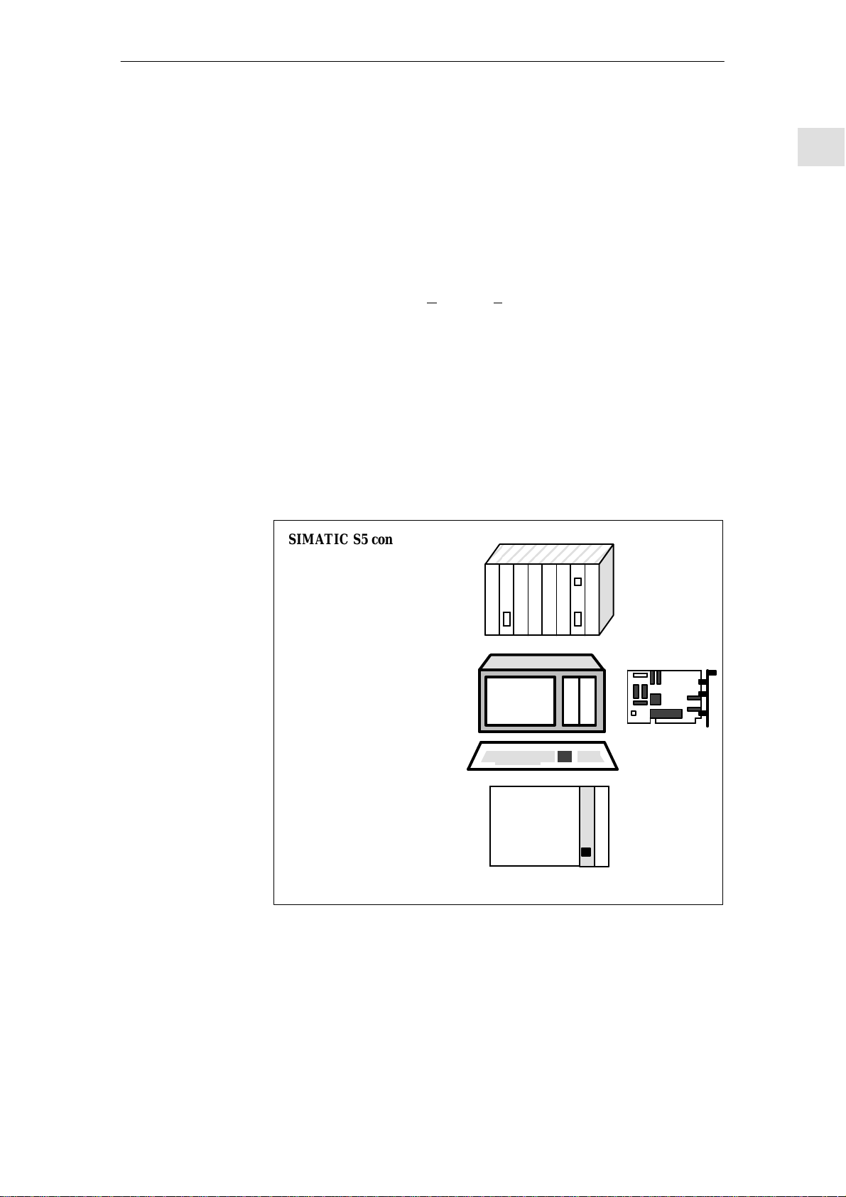
The following devices can be master stations:
SIMATIC S5 control
115U
135U
155U
with IM 308–B,
IM 308–C interface
Programming device
PG 730, PG 750 or PG 770
with CP 5410–S5DOS/ST
interface
SINUMERIK 805SM
SINUMERIK 840C
SIROTEC ACR 20
with module IM 329–N, master
or other master stations with PROFIBUS–DP
Fig. 1-1 Master stations
SINUMERIK
SIROTEC
+
or
Siemens AG 1995 All Rights Reserved 6ZB5 430–0BH02–0AA1
SIROTEC ACR 20, SINUMERIK 805SM / 840C (BS)
1-1
Page 12
1 General
04.95Description
1
Slave stations
Example
The following can be slave stations:
Distributed I/O devices
e. g.
ET 200B
ET 200U
ET 200C
S5–95U–DP
SINUMERIK 805SM
SINUMERIK 840C
SIROTEC ACR 20
SINUMERIK
or
SIROTEC
with IM 329–N, DP slave module
or other PROFIBUS–DP slaves
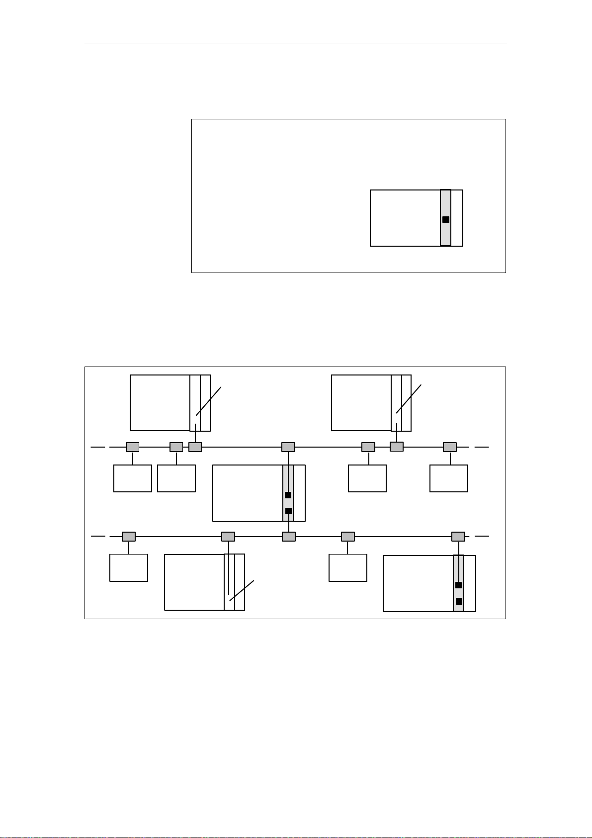
Fig. 1-2 Slave stations
The diagram below gives an example of how to connect the master and slave
stations to the SINEC L2–DP field bus:
PG
Interface module
CP 5410–S5DOS/ST
master
Field bus SINEC L2–DP
Slaves
ET 200
SINUMERIK
or
SIROTEC
with interface
module
IM 329–N
Slaves
PG
Interface module
CP 5410–S5DOS/ST
master
Fig. 1-3 Using the module IM 329–N as a slave and master
Slave
Master
ET 200ET 200
SIMATIC
S5–155U
ET 200
Field bus SINEC L2–DP
Interface module
IM 308–B/C
master
ET 200ET 200
SINUMERIK
or
SIROTEC
with interface
module
IM 329–N
J
1-2
6ZB5 430–0BH02–0AA1 Siemens AG 1995 All Rights Reserved
SIROTEC ACR 20, SINUMERIK 805SM / 840C (BS)
Page 13
04.95 Description
2.1 Module IM 329–N, master and slave
Hardware
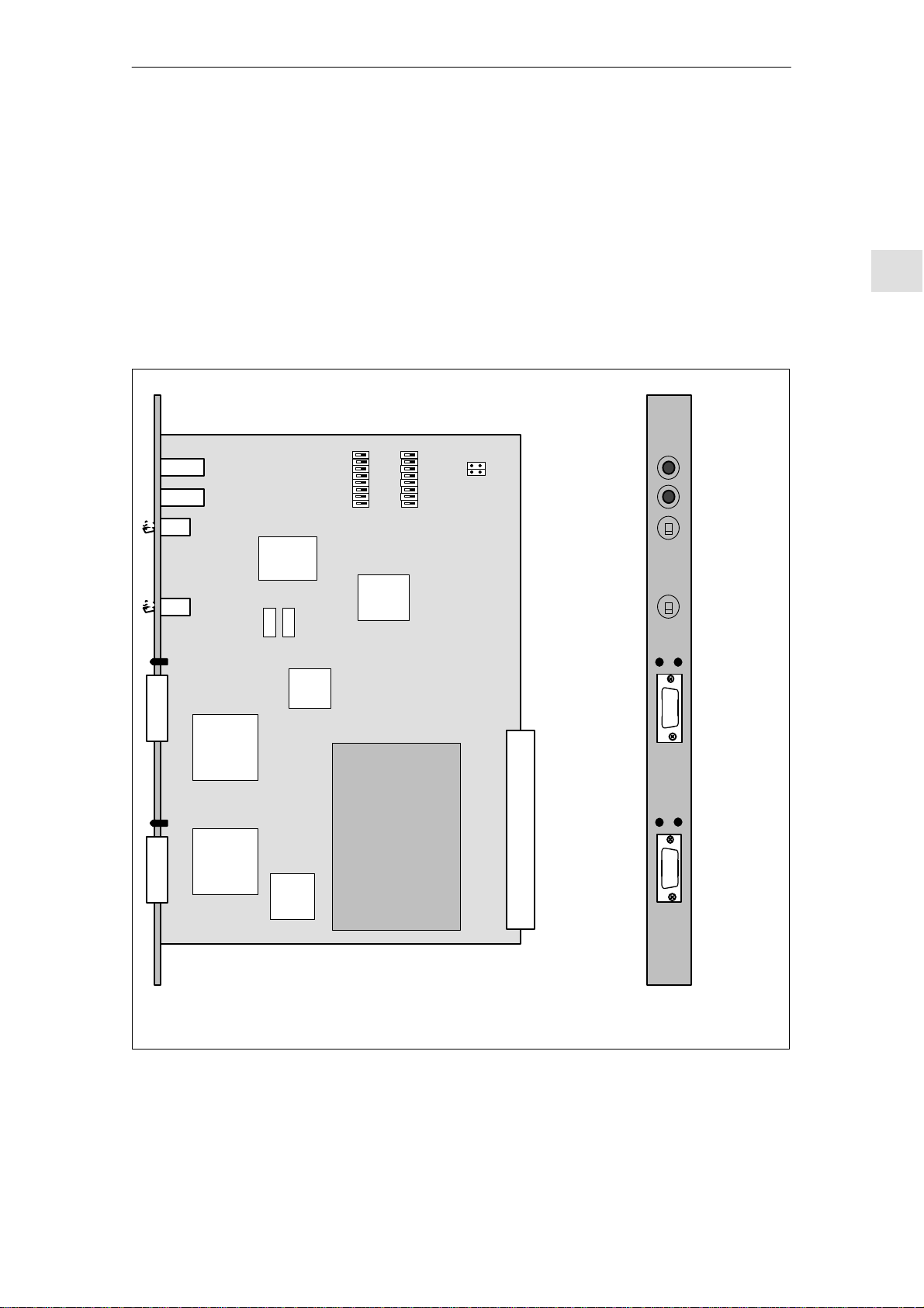
2.1 Module IM 329–N, master and slave
Order No.: 6FC5 012–0CA02–0AA0
ON
S2.
8
X339
5
3
1
X21
DC/DC
converter
Slave
DC/DC
converter
Master
FEPROM
Quartz
Quartz
SPC
Dual
port
RAM
(DPR)
ON
8
5
3
1
S3.
80C32
Master
module
0
10
1
10
100–199
0–99
PARAMETERIZATION
(+ Station address slave = 0)
RUN
(+ Station address slave
between 3 and 124)
RUN
(green LED)
Slave
ACCESS
(green LED)
Bus connector
Master
2
2
Station
address
for slave
Units place
Tens place
Hundreds place
Operating
mode
master
Status display
FAULT
(red LED)
Interface
X111
Status display
FAULT
(red LED)
Interface
X112
X339: Both jumpers open
Fig. 2-1 Module IM 329–N, master and slave
Siemens AG 1995 All Rights Reserved 6ZB5 430–0BH02–0AA1
SIROTEC ACR 20, SINUMERIK 805SM / 840C (BS)
2-1
Page 14

2.2 Jumper settings
2.2 Jumper settings
2.2.1 Jumper settings on the slave
04.95Description
2
Selecting the
control system
(S2.5, S2.6, S2.7
and S2.8)
Setting of address
range (number of
input and output
bytes) (S2.1 and
S2.2)
The module can be used in the control systems listed. The control type must
be set with switches S2.5, S2.6, S2.7 and S2.8 as follows:
S2.5 S2.6 S2.7 S2.8
SINUMERIK 805SM OFF ON OFF ON
SIROTEC ACR 20 ON ON ON ON
SINUMERIK 840C ON ON ON ON
Note
The IM 329–N module can only be used for SINUMERIK 805SM in the
central controller.
Switches S2.1 and S2.2 must be set according to the table below in order to
set the address range of 4, 8, 16 or 32 input or output bytes.
Address range S2.1 in position S2.2 in position
4 bytes OFF OFF
8 bytes OFF ON
16 bytes ON OFF
32 bytes ON ON
2-2
Note
Address range of, for example, 4 bytes means that 4 input bytes and 4 output
bytes are available with the same base address.
6ZB5 430–0BH02–0AA1 Siemens AG 1995 All Rights Reserved
SIROTEC ACR 20, SINUMERIK 805SM / 840C (BS)
Page 15
04.95 Description
2.2 Jumper settings
Setting the base
address
(S3.1 to S3.8)
Base address for
4-byte address range
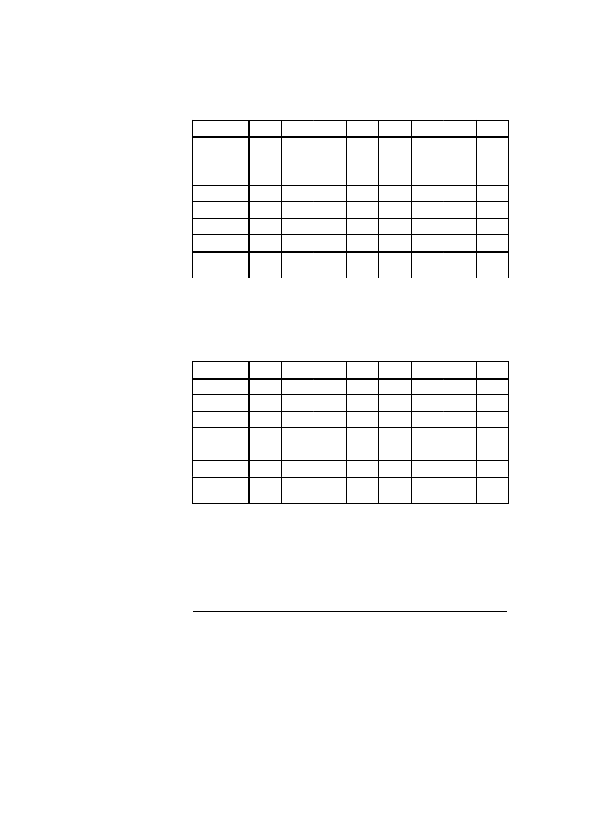
The following switches are used to set the module numbers (base address)
S3.1 to S3.8 for an address range of 4 bytes
S3.2 to S3.8 for an address range of 8 bytes
S3.3 to S3.8 for an address range of 16 bytes
S3.4 to S3.8 for an address range of 32 bytes
Note
The switches not required for the 8, 16 and 32–bytes address ranges are irrelevant and any setting is permissible.
Switch S2.1 = OFF and S2.2 = OFF
Base address S3.8 S3.7 S3.6 S3.5 S3.4 S3.3 S3.2 S3.1
0 ON ON ON ON ON ON ON ON
4 ON ON ON ON ON ON ON OFF
8 ON ON ON ON ON ON OFF ON
12 ON ON ON ON ON ON OFF OFF
16 ON ON ON ON ON OFF ON ON
: : : : : : : : :
1020 OFF OFF OFF OFF OFF OFF OFF OFF
Significance 2
=512
9
8
2
=256
7
2
=128
2
=64
6
2
=32
5
2
=16
4
2
=8
3
=4
2
2
2
Base address for
8-byte address range
Switch S2.1 = OFF and S2.2 = ON
Base address S3.8 S3.7 S3.6 S3.5 S3.4 S3.3 S3.2 S3.1
0 ON ON ON ON ON ON ON x
8 ON ON ON ON ON ON OFF x
16 ON ON ON ON ON OFF ON x
24 ON ON ON ON ON OFF OFF x
32 ON ON ON ON OFF ON ON x
: : : : : : : :
1016 OFF OFF OFF OFF OFF OFF OFF x
Significance 2
=512
9
8
2
=256
2
=128
x: Switch position of no significance
Siemens AG 1995 All Rights Reserved 6ZB5 430–0BH02–0AA1
SIROTEC ACR 20, SINUMERIK 805SM / 840C (BS)
7
2
=64
6
2
=32
5
2
=16
4
2
=8
3
2-3
Page 16
2.2 Jumper settings
04.95Description
2
Base address for
16-byte address range
Base address for
32-byte address range
Switch S2.1 = ON and S2.2 = OFF
Base address S3.8 S3.7 S3.6 S3.5 S3.4 S3.3 S3.2 S3.1
0 ON ON ON ON ON ON x x
16 ON ON ON ON ON OFF x x
32 ON ON ON ON OFF ON x x
48 ON ON ON ON OFF OFF x x
54 ON ON ON OFF ON ON x x
: : : : : : :
1008 OFF OFF OFF OFF OFF OFF x x
Significance 2
=512
9
8
2
=256
7
2
=128
2
=64
6
2
=32
5
2
=16
4
x: Switch position of no significance
Switch S2.1 = ON and S2.2 = ON
Base address S3.8 S3.7 S3.6 S3.5 S3.4 S3.3 S3.2 S3.1
0 ON ON ON ON ON x x x
32 ON ON ON ON OFF x x x
64 ON ON ON OFF ON x x x
96 ON ON ON OFF OFF x x x
: : : : : :
992 OFF OFF OFF OFF OFF x x x
Significance 2
=512
9
8
2
=256
7
2
=128
2
=64
6
2
=32
5
Example of address
setting
2-4
x: Switch position of no significance
Note
Base addresses are only possible for 4–byte, 8–byte, 16–byte or 32–byte
steps depending on the address range. For example, an address range of 32
bytes permits only 0, 32, 64, 96 etc. as initial addresses.
Address range = 8 bytes and the base address is to be 24 ⇒
S2.1 = OFF and S2.2 = ON
S3.8, S3.7, S3.6, S3.5, S3.4 = ON and S3.3, S3.2 = OFF
The assigned input and output area is from IB 24/QB 24 to IB 31/QB 31.
6ZB5 430–0BH02–0AA1 Siemens AG 1995 All Rights Reserved
SIROTEC ACR 20, SINUMERIK 805SM / 840C (BS)
Page 17
04.95 Description
2.2 Jumper settings
Danger
!
An incorrect setting of the base address (e.g. dual address assignment or address conflict with other I/O modules) results in “wrong signal states” and
can cause an undefined behaviour of the control and the machine!
2
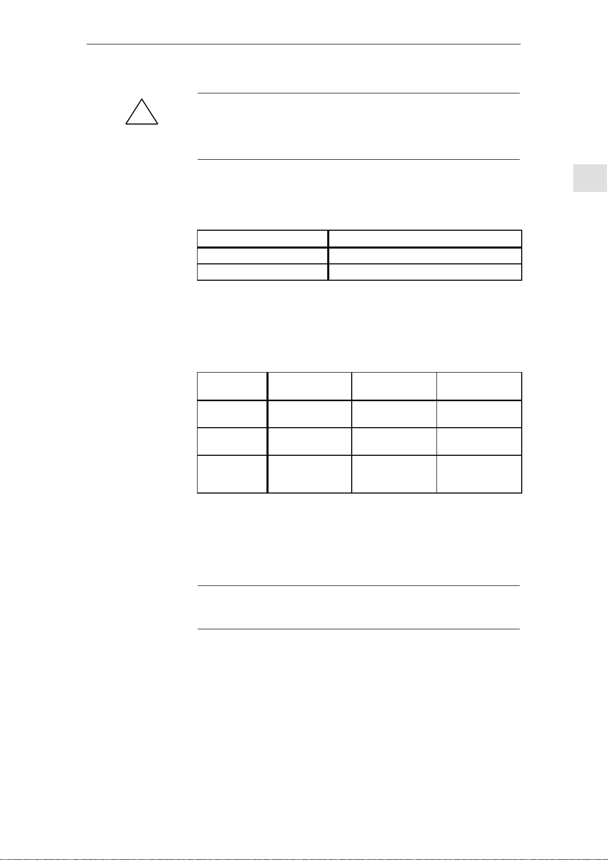
Enable slave
(S2.3)
I/O ranges
S2.3 must be used to enable the slave functionality.
Switch S2.3 in position Function
OFF Slave disabled
ON Slave enabled
In assigning the slaves, please note that the following I/O ranges are available on the SIROTEC ACR 20, SINUMERIK 805SM and SINUMERIK 840C
controls:
SINUMERIK
805SM (SW4)
Inputs IB 0 to IB 47 I 1 to I 1024
Outputs QB 0 to QB 47 Q 1 to Q 1024
Physical interface without
process image
– – PB 0 to PB 255
SIROTEC ACR 20
(SW5)
(IB 0 to IB 127)
(QB 0 to QB 127)
SINUMERIK 840C
(SW4)
IB 0 to IB 127
QB 0 to QB 127
For the allocation of the I/O range for each control see:
Reference: /3/, SINUMERIK 805SM,
Interface Description, Part 2 – Connection Conditions
Reference: /4/, SIROTEC ACR 20, Configuration Instructions
Note
The I/O range must be addressed without gaps with SIROTEC ACR 20
Reference: /5/, SINUMERIK 840C
Interface Description, Part 2 – Connection Conditions
Siemens AG 1995 All Rights Reserved 6ZB5 430–0BH02–0AA1
SIROTEC ACR 20, SINUMERIK 805SM / 840C (BS)
2-5
Page 18

2.2 Jumper settings
2.2.2 Jumper settings on the master
04.95Description
2
Enable master
(S2.4)
The master functionality must be enabled via S2.4.
Switch S2.4 in position Function
OFF Master disabled
ON Master enabled
Note
The addresses on the master are routed with the parameterization software
COM ET 200 (see Sections 3 and 5).
2-6
6ZB5 430–0BH02–0AA1 Siemens AG 1995 All Rights Reserved
SIROTEC ACR 20, SINUMERIK 805SM / 840C (BS)
Page 19

04.95 Description
2.3 Elements on the front plate
2.3 Elements on the front plate
2.3.1 Elements for the slave
Station address
Status display of
the slave (LEDs)
The rotary switch is used to set the units place (first switch from top) and the
tens place (second switch from top) of the station address.
The hundreds place of the station address depends on the setting of the toggle
switch (upper position = 1 x 100, lower position = 0 x 100). Valid station addresses are between 3 and 124.
Note
The software limits the station address to the range from 3 to 124.
A change in station address does not become active until after a restart of
the control.
The status display (FAULT and RUN LED) can indicate the following states
of the SINEC L2–DP slave module.
RUN
(green LED)
off on The module is being initialized
on off Normal operating state, slave in cyclic operation
Other states Fault (see Section 4.5)
FAULT
(red LED)
Remark
(this state only lasts for a short period of time)
2
Interface for slave
Via the interface X111 (SUB–D, socket, 9–way) the slave is connected to the
SINEC L2–DP field bus.
Note
T o connect up to the SINEC L2–DP field bus, the bus connectors with the
following order numbers are required:
Order number Designation
6ES5 762–2AA12 SINEC L2 bus connector (degree of protection IP 20, without
heavy–duty thread socket)
6ES5 762–2AA21 SINEC L2 bus connector (degree of protection IP 20, with
heavy–duty thread socket)
For information about the bus cable and the bus connector see:
Reference: /1/, ET 200 Distributed I/O System Manual
Siemens AG 1995 All Rights Reserved 6ZB5 430–0BH02–0AA1
SIROTEC ACR 20, SINUMERIK 805SM / 840C (BS)
2-7
Page 20

2.3 Elements on the front plate
2.3.2 Elements for the master
04.95Description
2
Status display of
the masters (LED)
Operating mode
!
The status display (ACCESS and FAULT LED) can indicate the following
messages:
ACCESS
(green LED)
on off Normal operating state
Other states Fault or message (see Section 5.4)
The operating mode of the master can be set with this toggle switch:
(+ station address for slave = 0)
(+ station address for slave between 3 and 124)
Caution
The parameterization data on the module are deleted if
FAULT
(red LED)
Position Operating mode
Top
Bottom
Remark
PARAMETERIZATION
RUN
the PARAMETERIZATION mode is set and
Interface for
master
a RESTART of the control is performed (see Section 5.3)
Via the interface X112 (SUB–D, socket, 9–way) the master is connected to
the SINEC L2–DP field bus.
Note
T o connect up to the SINEC L2–DP field bus, the bus connectors with the
following order numbers are required:
Order number Designation
6ES5 762–2AA12 SINEC L2 bus connector (degree of protection IP 20, without
heavy–duty thread socket)
6ES5 762–2AA21 SINEC L2 bus connector (degree of protection IP 20, with
heavy–duty thread socket)
For information about the bus cable and the bus connector see:
Reference: /1/, ET 200 Distributed I/O System Manual
2-8
6ZB5 430–0BH02–0AA1 Siemens AG 1995 All Rights Reserved
SIROTEC ACR 20, SINUMERIK 805SM / 840C (BS)
Page 21

04.95 Description
2.4 Technical data
2.4 Technical data
Type Value
PCB format Double–height Eurocard format
(160 x 233.4 mm)
Width of front panel 1 1/3 SEP, metal (1 SEP = 15.24 mm)
Front connector 9–pin, SUB–D female connector
(bus interface)
Degree of protection IP 00 to DIN 40050
Permissible ambient temperature
during operation
Transport and storage temperature – 40 to + 70° Celsius
Humidity class F to DIN 40040
Shock resistance Class 12 to SN 29010
Mass 400 g
Power supply + 5 V (+/– 5%), 1.6 A
0 to + 55° Celsius
max
2
J
Siemens AG 1995 All Rights Reserved 6ZB5 430–0BH02–0AA1
SIROTEC ACR 20, SINUMERIK 805SM / 840C (BS)
2-9
Page 22

04.95 Description
3.1 Installation
COM ET 200 for IM 329–N
With the COM ET 200 parameterization software, you can configure the
IM 329–N master, create the address list and analyze diagnostics data.
Version of
COM ET 200
3.1 Installation
For information
about
In this description, it is assumed you have the parameterization software
COM ET 200 Version 4.x.
Which PG/PC can be operated on the SINEC L2–DP bus?
How is the CP 5410 S5DOS/ST installed?
How is the COM ET 200 installed on the PG?
see:
Reference: /1/, ET 200 Distributed I/O System Manual
3
3
Installation of the
type file for
IM 329–N, slave
For parameterization of the slave interface of the IM 329–N with COM ET
200, the appropriate type file is required. The type files have the following
designations:
File name Designation
SI8024TD.200 German
SI8024TE.200 English
SI8024TF.200 French
SI8024TS.200 Spanish
SI8024TI.200 Italian
Note
If the appropriate type file is not contained in the directory of COM ET 200,
please contact your SIEMENS representative.
Siemens AG 1995 All Rights Reserved 6ZB5 430–0BH02–0AA1
SIROTEC ACR 20, SINUMERIK 805SM / 840C (BS)
3-1
Page 23

3.2 COM ET 200 parameterization software
3.2 COM ET 200 parameterization software
04.95Description
3
Principle
Start–up and
language selection
Function selection
With the ET 200 Distributed I/O Sysrem, the master is always configured
with the COM ET 200 configuration software. The parameters for the slaves
are then transferred during system start–up.
After start–up of the COM ET 200 package, the required language can be
selected. Five languages are available. After that, COM ET 200 branches to
the screen form FUNCTION SELECTION.
This screen form is the main screen form. Here, you are prompted to specify
a program file in which to store the parameters and data entered. Select a
name with up to 6 letters. Blanks are filled in by COM ET 200 (e.g.
“C:BEISP@ET.200”).
In this screen form, you can press one of the following softkeys:
F1: Enter the ET 200 system parameters
F2: Configuration
F3: Transfer functions
F4: Plant documentation
F5: Start–up / test
F6: Diagnostics
Selecting the
master type
ET 200
system parameters
Configuring
After input of the new program file and confirmation, e.g., of softkey F1 in
the function selection screen form, you are prompted to select the master
type.
Please select:
<F1>: DP master is an IM 308–B
<F3>: General DP master
Fig. 3-1 Selecting the master type
After you have selected the master type, the following functions are available:
Here you enter all parameters required for the correct operation of system ET
200, such as baud rate, type of addressing, CPU type, and behaviour in the
case of a station failure.
Enter the CONFIGURING data of each individual ET 200 slave station in the
configuring screen form.
3-2
6ZB5 430–0BH02–0AA1 Siemens AG 1995 All Rights Reserved
SIROTEC ACR 20, SINUMERIK 805SM / 840C (BS)
Page 24

04.95 Description
3.2 COM ET 200 parameterization software
TRANSFER
functions
Address assign–
ment and system
documentation
The TRANSFER FUNCTIONS screen form permits the following for a memory module:
Programming of a memory module with system parameters and configu-
ration data for the IM 308–B.
Read–in of a memory module into a program file
Comparison of the creation data from program file and memory module.
Moreover, you can transfer the configuration data created with COM ET 200
to a SINEC L2–DP master (such as the IM329–N)
This screen form gives you information about the current configuration status, e.g. via the
Set ET 200 system parameters
Assigned station numbers
Station–oriented address assignment for one station you obtain the infor-
mation:
Query:
In which slot is the module inserted?
What addresses do the inputs and outputs have?
Address assignment range–oriented for one address range each
(e.g. the P range):
Which inputs and outputs are assigned to which stations?
T o which slot and to which module type is each input and output
assigned?
3
Startup/test
Diagnostics
You can also print out the current configuration status.
This screen form enables you to verify whether the configured configuration
of a station corresponds to the actual configuration.
Form the STARTUP/TEST screen form you automatically enter the screen
form MODULE SELECTION or STATUS/FORCE.
In the STATUS/FORCE screen form, you can see the signal condition of the
inputs of all selected modules. It is also possible to force the outputs of the
modules selected.
The DIAGNOSTICS OVERVIEW screen form lists the stations for which
diagnostics data exist.
Siemens AG 1995 All Rights Reserved 6ZB5 430–0BH02–0AA1
SIROTEC ACR 20, SINUMERIK 805SM / 840C (BS)
3-3
Page 25

3
04.95Description
3.2 COM ET 200 parameterization software
In the INDIVIDUAL DIAGNOSTICS screen form, you can obtain the
following information about the required station:
S Stations number
S Station type
S Station designation
S Station status
S Device and ID–related diagnostics
Note
For operation of the software and detailed information on the functions and
parameters of the COM ET 200, please refer to
Reference: /1/, ET 200 Distributed I/O System Manual
J
3-4
6ZB5 430–0BH02–0AA1 Siemens AG 1995 All Rights Reserved
SIROTEC ACR 20, SINUMERIK 805SM / 840C (BS)
Page 26

04.95 Description
4.1 Notes on parameterization of the slaves
Description of the Slave Functionality
4.1 Notes on parameterization of the slaves
Here are some notes that must be observed when the IM 329–N is used as a
slave station in the ET 200 Distributed I/O System. For example, the master
IM 308–B or IM 329–N can be used.
Note
Page addressing is not possible!
Prerequisites
for slave parameterization
If the module IM 308–B is the master
PG/PC with COM ET 200 (V4.x)
If the module IM 329–N is the master
See Section 5
4
4
ET 200 system
parameters if the
master IM 308–B
is used
ET 200 system
parameter if the
master IM 329–N
is used
Note
About the system parameter BUS PROFILE:
Select the bus profile “DP standard” or
“DP/FMS operation”
About the baud rate:
Baud rates up to 1500 kBaud are possible.
Note
See Section 5
Siemens AG 1995 All Rights Reserved 6ZB5 430–0BH02–0AA1
SIROTEC ACR 20, SINUMERIK 805SM / 840C (BS)
4-1
Page 27

4.1 Notes on parameterization of the slaves
04.95Description
4
Configuration
There is a separate configuration screen form to configure the slave interface
of the IM 329–N. T o make this screen form available, the appropriate type
file must be installed (see Section 3.1).
Note
Station No.:
Station numbers from 3 to 124 are allowed.
Station type:
Station type “IM 329–N slave DP” must be used to configure station type
IM 329–N, DP slave.
Station name:
Here you can enter a name for the station (all keyboard characters are
allowed).
First free address:
The address of the first free byte as seen from the master is displayed for
DI (digital inputs)
DQ (digital outputs)
The first address can also be entered and defined manually.
Configuration field:
Depending on the address range, you can enter the following address
identifiers in these input fields:
Address range Address ID 0 Address ID 1
4 bytes
8 bytes 55
16 bytes 63
32 bytes (2 16 bytes) 63
51
dec
dec
dec
dec
63
–
–
–
dec
The address IDs follow DIN E 19245 Part 3.
Pressing the ENTER softkey stores the configuration data for this station
in the specified program file.
4-2
6ZB5 430–0BH02–0AA1 Siemens AG 1995 All Rights Reserved
SIROTEC ACR 20, SINUMERIK 805SM / 840C (BS)
Page 28

04.95 Description
4.2 Configuration example
4.2 Configuration example for slave
The text below describes the configuration data for integrating a slave IM
329–N into an already existing ET 200 distributed I/O system.
Assumptions
The configuration data are stored in the program file C:BEISP@ET.200.
Slave stations exist with station numbers 3 and 4.
A SIMATIC S5–115U is available as master PLC (linear addressing, I/O
range =P, 256 input and output bytes).
Configuration data of a new station:
Station address and name; 5, example for IM 329–N slave
First available address: DI: 96, DQ: 96
Address range = 4 bytes ⇒ Address identifier = 51
(see Section 4.1)
Based on the above assumptions, the CONFIGURING screen form must be
parameterized as follows:
4
Program file selected C: BEISP@ET.200
CONFIGURING
Station No.: Area: Station type:
Station name:
First available address:
Configuration:
5P
Example for IM 329–N Slave
DI: DQ: AI: AQ:
96 96
Module address: I: Q:
0. 1. 2. 3. 4. 5. 6. 7.
51
8. 9. 10. 11. 12. 13. 14. 15.
16. 17. 18. 19. 20. 21. 22. 23.
24. 25. 26. 27. 28. 29. 30. 31.
F1
STATION
+
Fig. 4-1 CONFIGURING screen form
F2 F3 F4 F5 F6 F7 F8
STATION
–
DELETE
STATION
NEW
STATION
SIMATIC S5 / COM ET 200
IM 329–N slave DP
ADDRESS
ASSIGNM. ENTER HELP EXIT
Siemens AG 1995 All Rights Reserved 6ZB5 430–0BH02–0AA1
SIROTEC ACR 20, SINUMERIK 805SM / 840C (BS)
4-3
Page 29

4
04.95Description
4.3 Procedure for installation and startup
4.3 Procedure for installation and startup
The following procedure is recommended for installation and startup of a
station with an IM 329–N, DP slave:
Set and check the following data on the module in accordance with Sec-
tion 2.2.1 :
– Control type
– Address range (number of input and output bytes)
– Base address
– Enable slave functionality
Install the module in the control:
– Switch off the control
– Plug the module into a valid slot, see information for the relevant con-
trol in
Reference: /3/, SINUMERIK 805SM,
Interface Description, Part 2 – Connection Conditions
Reference: /4/, SIROTEC ACR 20, Configuration Instructions
Reference: /5/, SINUMERIK 840C
Interface Description, Part 2 – Connection Conditions
– Set the station address on the front panel in accordance with Section
2.3.1.
– Connect the module to the SINEC L2–DP field bus
– Switch on the control (POWER ON) and perform a RESTART of the
PLC if required
Note
On the SINUMERIK 840C, I/O modules that have just been slotted in are
not recognized until a cold RESTART of the control is performed.
Modify the configuration of the master (e.g. IM 308–B):
– Add the configuration data of the new station to the existing program
file
– For the IM 308–B: Write to the memory module
For the IM 329–N, master: perform DOWNLOAD (see Section 5)
– Program and activate monitoring and diagnostics functions on the ma-
ster and slave sides.
4-4
6ZB5 430–0BH02–0AA1 Siemens AG 1995 All Rights Reserved
SIROTEC ACR 20, SINUMERIK 805SM / 840C (BS)
Page 30

04.95 Description
4.4 Example of application
4.4 Example of application
The SINUMERIK 805SM, SINUMERIK 840C and SIROTEC ACR 20 controls are to be linked via the ET 200 distributed I/O system and via a master
control, such as the SIMATIC S5–115U (master PLC link).
Master
SIMATIC
S5–115U
SINEC L2–DP
Slaves
SINUMERIK
805SM
Fig. 4-2 Example of application: Master PLC link
Assumptions for
the example
The following assumptions are made for the example:
The configuration data are stored in the BEISP@ET.200 program file.
SINUMERIK
A SIMATIC S5–115U is used as master PLC (linear addressing,
I/O area = P, 256 input and output bytes, first available address is IB 96 /
QB 96.
The station addresses 3, 4 and 5 are to be set on the IM 329–N slave inter-
face modules of the individual controls.
The address range for the stations 3, 4, 5 is to be 4 bytes, 8 bytes, 32 bytes
and the base addresses for the input and output bytes are to be IB 16/
QB 16, IB 40/QB 40 und IB 64 (I 513 to I 520)/QB 64 (Q 513 to Q 520).
The ET 200 system parameters have been determined for this application
and entered in the program file.
840C
SIROTEC
ACR 20
4
Siemens AG 1995 All Rights Reserved 6ZB5 430–0BH02–0AA1
SIROTEC ACR 20, SINUMERIK 805SM / 840C (BS)
4-5
Page 31

4.4 Example of application
04.95Description
4
Hardware
settings
For use in the controls, the individual SINEC L2–DP slave interface modules
are to be set as follows:
Selection of the control system
SINUMERIK 805SM SINUMERIK 840C SIROTEC ACR 20
ON
S2.8
S2.7
S2.6
S2.5
ON
S2.8
S2.7
S2.6
S2.5
ON
S2.8
S2.7
S2.6
S2.5
Setting of address range
SINUMERIK 805SM SINUMERIK 840C SIROTEC ACR 20
ON S2.1
S2.2
ON S2.1
S2.2
ON S2.1
S2.2
4 byte 8 byte 32 byte
Setting of base address
SINUMERIK 805SM SINUMERIK 840C SIROTEC ACR 20
S3.8
ON
S3.1
IB 16/QB 16
ON S3.2
IB 40/QB 40 IB 64/QB 64
S3.8
ON S3.4
(I 513/Q 513)
Enable slave
Master disabled
ON S2.3
S2.4
Slave enabled
Station address for slave (to be set on the front panel)
SINUMERIK 805SM SINUMERIK 840C SIROTEC ACR 20
Units place = 3 Units place = 4 Units place = 5
T ens place = 0 Tens place = 0 T ens place = 0
Hundreds place = 0 Hundreds place = 0 Hundreds place = 0
S3.8
4-6
6ZB5 430–0BH02–0AA1 Siemens AG 1995 All Rights Reserved
SIROTEC ACR 20, SINUMERIK 805SM / 840C (BS)
Page 32

04.95 Description
4.4 Example of application
Configuring
(configuration
Based on the assumptions for the individual stations, the CONFIGURING
screen form is to be parameterized as follows:
data)
Program file selected C:BEISP@ET.200
CONFIGURING
Station No.: Area: Station type:
Station name:
First available address:
Configuration:
3P
IM 329–N slave interface module SINUMERIK 805SM
DI: DQ: AI: AQ:
96 96
Module address: I: Q:
0. 1. 2. 3. 4. 5. 6. 7.
51
8. 9. 10. 11. 12. 13. 14. 15.
16. 17. 18. 19. 20. 21. 22. 23.
24. 25. 26. 27. 28. 29. 30. 31.
Fig. 4-3 Configuration of the slave in SINUMERIK 805SM
SIMATIC S5 / COM ET 200
IM 329–N slave DP
4
Program file selected BEISP@ET.200
CONFIGURING
Station No.:
Station name:
First available address:
Configuration:
Area
4P
IM 329–N–slave interface module SINUMERIK 840C
DI: DQ: AI: AQ:
100
Station type:
100
Module address:
0. 1. 2. 3. 4. 5. 6. 7.
55
8. 9. 10. 11. 12. 13. 14. 15.
16. 17. 18. 19. 20. 21. 22. 23.
24. 25. 26. 27. 28. 29. 30. 31.
Fig. 4-4 Configuration of the slave in SINUMERIK 840C
SIMATIC S5 / COM ET 200
IM 329–N slave DP
I: Q:
Siemens AG 1995 All Rights Reserved 6ZB5 430–0BH02–0AA1
SIROTEC ACR 20, SINUMERIK 805SM / 840C (BS)
4-7
Page 33

4.4 Example of application
04.95Description
4
Program file selected: C:BEISP@ET.200
CONFIGURING
Station number: Area: Station type:
Station name:
First available address:
Configuration:
5P
IM 329–N slave interface module in the SIROTEC ACR 20
DI: DQ: AI: AQ:
108
108
Module address: I: Q:
0. 1. 2. 3. 4. 5. 6. 7.
63
63
8. 9. 10. 11. 12. 13. 14. 15.
16. 17. 18. 19. 20. 21. 22. 23.
24. 25. 26. 27. 28. 29. 30. 31.
Fig. 4-5 Configuration of the slave in SIROTEC ACR 20
SIMATIC S5 / COM ET 200
IM 329–N slave DP
4-8
6ZB5 430–0BH02–0AA1 Siemens AG 1995 All Rights Reserved
SIROTEC ACR 20, SINUMERIK 805SM / 840C (BS)
Page 34

04.95 Description
4.4 Example of application
Data transfer
diagram
The diagram below illustrates the data transfer of the input and output signals
between the master (SIMATIC S5–115U) und the slaves
(SINUMERIK 805SM, SINUMERIK 840C and SIROTEC ACR 20).
SIMATIC S5–115U
IB 96
:
IB 99
IB 100
:
IB 107
IB 108
:
IB 139
QB 96
:
QB 99
QB 100
:
QB 107
QB 108
:
QB 139
4
IB 16
:
IB 19
QB 16
:
QB 19
IB 40
:
IB 47
QB 40
:
QB 47
IB 64
(I 513
to
I 520)
:
IB 95
(I 753
to
I 760)
SINUMERIK 805SM SINUMERIK 840C SIROTEC ACR 20
Fig. 4-6 Overview of data transfer
QB 64
(Q 513
to
Q 520)
:
QB 95
(Q 753
to
Q 760)
Siemens AG 1995 All Rights Reserved 6ZB5 430–0BH02–0AA1
SIROTEC ACR 20, SINUMERIK 805SM / 840C (BS)
4-9
Page 35

4.5 Status display messages
4.5 Status display messages
4.5.1 Normal operating state
Normal operation is displayed via the status display as follows:
04.95Description
4
RUN
(green LED)
on off Normal operation, slave is in cyclic mode
FAULT
(red LED)
4.5.2 Fault during data transmission
The following faults are possible in data transmission:
Slave disconnected from the bus (e.g. bus connector unplugged)
Master broken down or switched off
Configuration of the slave does not correspond to the configuration data
of the master
Status display
slave
If threshold monitoring (system parameter) is activated, a fault in data transmission (i.e. a bus fault) is displayed by the STATUS DISPLAY SLAVE as
follows:
RUN
(green LED)
on on Fault during data transmission
FAULT
(red LED)
Meaning
Meaning
Effects of fault
!
4-10
Reset of the inputs implemented by the slave in the slave station.
Cyclic attempt of the module to link to the SINEC L2-DP bus.
Warning
If no response monitoring is activated, the inputs of the station concerned are
also not reset if a fault occurs but they remain unchanged.
6ZB5 430–0BH02–0AA1 Siemens AG 1995 All Rights Reserved
SIROTEC ACR 20, SINUMERIK 805SM / 840C (BS)
Page 36

04.95 Description
module
4.5 Status display messages
Monitoring of
cyclic operation on
the slave side by
The user can detect a fault in data transmission, that is, a fault of the cyclic
operation between master and slave on the slave side by means of a userdefined sign-of-life bit (pre-condition: threshold monitoring activated).
the user
Example
An output bit of the slave to be monitored is set on the master side and the
signal state of the corresponding input bit is read on the slave side and it is
evaluated as follows:
1 signal: Cyclic operation between master and slave running
0 signal: Fault during cyclic operation, data transmission fault.
Based on the signal state of this input bit, the user can have a suitable error
message displayed and can program the behaviour of the control in the case
of this fault.
4.5.3 Fault on the module (system error message)
System error messages are indicated by the flashing of the slave status
indicator (FAULT, red LED).
Possible faults
4
Consequences
Slave status indicator
FAULT LED, red
1 time on, pause, 1 time on, ... Slave functionality and
2 times on, pause, 2 times on, ..
3 times on, pause, 3 times on, ..
4 times on, pause, 4 times on, ..
Error message Comment
Slave must be enabled
master functionality
disabled
Hardware fault on
module
via S2.3, master must be
enabled via S2.4
(see Section 2.2.1)
Replace module
Interface to the local bus of the control is disabled. When the module is
accessed, the control reacts with acknowledgement delay (TO).
Cyclic data transmission between master and slave is terminated.
Siemens AG 1995 All Rights Reserved 6ZB5 430–0BH02–0AA1
SIROTEC ACR 20, SINUMERIK 805SM / 840C (BS)
4-11
Page 37

4.6 Diagnostics functions in the STEP 5 program of the master IM 308–B
4.6 Diagnostics functions in the STEP 5 program of the
master IM 308–B
04.95Description
4
General notes on
diagnostics
The STEP 5 program of the IM 308–B master can request and evaluate the
following diagnostics messages via the IM 329–N slave:
Diagnostics type Request Description
Diagnostics “Overview” 127,0 Records all the stations for which
diagnostics data exist
Diagnostics “Parameter assignment and addressability”
Station status n,0
Device–related diagnostics
(stations diagnostics)
Identifier–related diagnostics
(module diagnostics)
n: Station number
126,n Records all stations that can be para-
meterized and addressed
Provides information about the status
n,1
n,2
n,3 Provides information about the status
n,4 Not used by slave IM 329–N
of the slave station
of the PLC in which slave IM 329–N
is slotted (PLC in RUN or in STOP?)
Diagnostics “Overview” and “Parameter assignment and addressability”
are described in
Reference: /1/, ET 200 Distributed I/O System Manual
Enabling
diagnostics
because they can be used on all slave stations.
The diagnostics function must first be enabled in the ET 200 SYSTEM PARAMETER screen form (Y) and a diagnostics address must be specified (default diagnostics address: 252).
Diagnostics:
Y
Diagnostics address: 252
The diagnostics address is the address of the diagnostics word. The diagnostics data area of the master can be accessed with the diagnostics word. If an
error occurs, the slave stations send the diagnostics data to the master.
The two diagnostics bytes of the diagnostics word will be referred to as
DIAGNOSTICS ADDRESS (default: I/O byte 252) and DIAGNOSTICS
ADDRESS +1 (default: I/O byte 253).
By combining different diagnostics, appropriate conclusions can be drawn
such as, for example, station with fault and can be contacted.
4-12
6ZB5 430–0BH02–0AA1 Siemens AG 1995 All Rights Reserved
SIROTEC ACR 20, SINUMERIK 805SM / 840C (BS)
Page 38

04.95 Description
4.6 Diagnostics functions in the STEP 5 program of the master IM 308–B
Immediately after diagnostics is called in the STEP 5 program, the
diagnostics data are accessed and the diagnostics message is given in the
diagnostics word.
.
.
.
Diagnostics dataDiagnostics word
Call
diagnostics
Read
diagnostics
.
.
.
Fig. 4-7 Request and read diagnostics
4
Important
diagnostics for
IM 329-N, slave
Structure and
requesting
diagnostics
For the slave IM 329–N the following diagnostics are of considerable
importance:
Station status
Device–oriented diagnostics (station diagnostics)
The diagnostics are loaded and transferred with the following instructions:
L KY (station number), (code) Station number 3 to 124
Code: 0 to 7
T PW 252 After that, the station diagnostics are
transferred to the diagnostics word
Eight words in each slave station are reserved for station status, device–
oriented (station diagnostics) and ID–oriented diagnostics (module
diagnostics).
Code Diagnostics address Diagnostics address + 1
0 Station status 1 Station status 2
1 Station status 3 Master address
2 Manufacturer ID
3 Header Device–oriented diagnostics
(station diagnostics)
4 Header ID–oriented diagnostics
(module diagnostics)
5 Unused Unused
6 Unused Unused
7 Unused Unused
Siemens AG 1995 All Rights Reserved 6ZB5 430–0BH02–0AA1
SIROTEC ACR 20, SINUMERIK 805SM / 840C (BS)
4-13
Page 39

4.6 Diagnostics functions in the STEP 5 program of the master IM 308–B
04.95Description
4
Requesting station
status and
evaluating
Code = 0 and
Code = 1
The bytes “Station status 1 to 3” provide information about the station. The
byte “Master address” contains the address of the master station that the slave
station has parameterized.
L KY n, 0 Load diagnostics for Code 0 (n=station number)
T PW 252 and transfer the diagnostics words
L KH 0004 Load the comparison word
L PW 252 Read the diagnostics word
!=F If the diagnostics word is not equal to the comparison word
BEB then
SPB FBx evaluate fault in FBx
L KY n, 1 Load diagnostics for Code 1 (n = station number)
T PW 252 and transfer the diagnostics word
L PW 252 Read and evaluate the diagnostics word
Code = 0 Station status 1 Station status 2
7654321076543210
Bit:
Slave station has been parameterized by another master
Slave station is not an
IM 329–N (parameter error)
Bit is always “0”
Function is not supported
Device–oriented or
ID–oriented diagnostics exists
The configuration data sent from the master to
the slave station does not match the structure
of the slave station
Slave station is not ready for
data exchange
Must be reparameterized
Slave station cannot continue
until fault is remedied
Bit is always “1”
Response monitoring is activated
Slave station is in
“FREEZE” mode
Slave station is in “SYNC” mode
Bit is always “0”
Slave station is deactivated
Slave station cannot be addressed
Note: Description of bits refers to the bit set.
Fig. 4-8 Structure of the diagnostics word after request with Code = 0
Code = 1 Station status 3 Master address
7654321076543210
Bit:
Without meaning
Fig. 4-9 Structure of the diagnostics word after request with Code = 1
6ZB5 430–0BH02–0AA1 Siemens AG 1995 All Rights Reserved
4-14
Address of the master
that has parameterized
the slave station
SIROTEC ACR 20, SINUMERIK 805SM / 840C (BS)
Page 40

04.95 Description
4.6 Diagnostics functions in the STEP 5 program of the master IM 308–B
Requesting
manufacturer ID
Code = 2
The byte “Manufacturer ID” describes the type of slave station.
L KY n, 2 Load diagnostics for Code 2 (n = station number)
T PW 252 and transfer the diagnostics words
L PW 252 Read and evaluate the diagnostics word
Code = 2 Manufacturer ID
7654321076543210
Bit:
The manufacturer ID for IM 329–N, DP slave is 8024
Fig. 4-10 Structure of the diagnostics word after request with Code = 2
Requesting and
reading deviceoriented
diagnostics
Code = 3
With the device–oriented diagnostics (station diagnostics) you can ascertain
whether the PLC is in RUN or STOP state.
L KY n, 3 Load diagnostics for Code 3 (n = station number)
T PW 252 and transfer the diagnostics words
L KH 0200 Read and evaluate the diagnostics word
L PW 252 Read the diagnostics word
!=F If the diagnostics word is not equal to the comparison word
BEB then
SPB FBx evaluate fault in FBx
hex
4
Code = 3 Header
Bit:
7654321076543210
Code for
device–
oriented
diagnostics
Fig. 4-11 Structure of the diagnostics word after request with Code = 3
Length of the device–
oriented diagnostics
incl. “Header”
(length = 2 bytes)
Station diagnostics
Always “0”
Bit = 1:
PLC STOP in the slave station
Siemens AG 1995 All Rights Reserved 6ZB5 430–0BH02–0AA1
SIROTEC ACR 20, SINUMERIK 805SM / 840C (BS)
4-15
Page 41

4.6 Diagnostics functions in the STEP 5 program of the master IM 308–B
4.6.1 Example: Diagnostics overview
04.95Description
4
.
.
.
L KY 127,n
T PW 252
L KH 0000
L PW 252
!=F
BEB
SPB FBx
.
.
.
Request diagnostics OVERVIEW:
Transfer value 127 for call of the diagnostics “Overview” in the “Diagnostics
address” byte (here I/O byte 252). The number of the station group
n = 0, 1, 2, ...7) is specified in the “Diagnostics address + 1” byte
(here I/O byte 253). The diagnostics OVERVIEW comprises station (n 16)
to station (n 16 + 15) for each station group.
The master writes the diagnostics message in the I/O word 252.
Read diagnostics OVERVIEW
If no station has sent
diagnostics message,
then end of block,
otherwise evaluate error
in FB x.
Diagnostics word from diagnostics OVERVIEW
Diagnostics address Diagnostics address + 1
Bit 7 6 5 4 3 2 1 0 Bit 7 6 5 4 3 2 1 0
Station Station
n16+7n16+6n16+5n16+4n16+3n16+2n16+1n16 n16
has sent a diagnostics message has sent a diagnostics message
+15
n16
+14
n16
+13
n16
+12
n16
+11
n16
+10
n16+9n16
You can use the following programming steps to check station 5 with
diagnostics OVER VIEW:
.
.
.
L KY 127,0
T PW 252
L PW 252
T MW 252
U M 252.5
SPB FBx
Call diagnostics OVERVIEW with station group 0
(stations 0 to 15) and
transfer into a
flagword.
If station 5 has sent a diagnostics message,
then evaluate error in FB x.
.
.
.
+8
4-16
6ZB5 430–0BH02–0AA1 Siemens AG 1995 All Rights Reserved
SIROTEC ACR 20, SINUMERIK 805SM / 840C (BS)
Page 42

04.95 Description
4.6 Diagnostics functions in the STEP 5 program of the master IM 308–B
Note
For detailed information on the diagnostics possibilities in the STEP 5
program of the master, please refer to
Reference: /1/, ET 200 Distributed I/O System Manual
4.6.2 Example: PLC STOP in the slave station
If it is found from the diagnostics that the station to be checked has an error
and can be contacted, the device-related diagnostics (station diagnostics) can
be used to detect the cyclic operation of the slave control:
.
.
.
L KY 5,3
T PW 252
L PW 252
L KH 0001
UW
L KH 0000
> < F
SPB FBy
.
.
.
Consequences of
a fault
Monitoring of
cyclic operation of
the slave station
by the user
Call station diagnostics from the SINEC L2-DP slave interface module.
Enter station number (here: 5; can be between 3 and 124) in the “diagnostics
address” byte. The byte “diagnostics address + 1” always has the value 3.
Read station diagnostics from the SINEC L2-DP slave interface module.
Load diagnostics word.
Is bit 0 of the “diagnostics address” byte
set?
If so,
then
no cyclic operation of the slave control (evaluate in FBy
correspondingly).
Reset of the inputs implemented by the slave in the master station.
A self-defined sign-of-life bit can enable the user to detect a fault in cyclic
operation of the slave station on the master side.
4
Example
Siemens AG 1995 All Rights Reserved 6ZB5 430–0BH02–0AA1
SIROTEC ACR 20, SINUMERIK 805SM / 840C (BS)
An output bit of the slave to be monitored is set on the slave side and on the
master side the signal state of the corresponding signal bit is read and
evaluated as follows:
1 signal: Cyclic operation of slave control running
0 signal: Fault during cyclic operation of slave control
Based on the signal state of this input bit, the user can have a suitable error
message displayed and can program the behaviour of the control should this
fault occur.
J
4-17
Page 43

04.95 Description
5.2 Information about configuring the master interface
Description of the Master Functionality
5
5.1 General information about the master interface of the IM 329–N
This section provides information about the use of the IM 329–N as a master
(master type: general DP master) in an ET 200 Distributed I/O System.
Note
For technical data, settings and operating elements of the module see
Section 2.
The structure of the SINEC L2–DP field bus (cable laying, shielding,
attenuation of interference voltage etc.) see:
Reference: /1/, ET 200 Distributed I/O System Manual
5
5.2 Information about configuring the master interface
Preconditions for
parameterizing the
master
The following preconditions must have been fulfilled before you can parameterize the master interface of the IM 329–N:
PG/PC with COM ET 200 (V4.x)
CP 5410 S5DOS/ST interface
Cable to connect PG/PC (CP 5410 S5DOS/ST interface) and IM 329–N
(X112 interface)
With length 1.5 m: 6XV 1830–1BH–15
With length 3 m: 6XV 1830–1BH–30
Siemens AG 1995 All Rights Reserved 6ZB5 430–0BH02–0AA1
SIROTEC ACR 20, SINUMERIK 805SM / 840C (BS)
5-1
Page 44

5.2 Information about configuring the master interface
04.95Description
5
Master type
ET 200 parameters
Bus parameters
During configuration you are prompted to select the master type.
Please select:
<F1>: DP master is an IM 308–B
<F3>: General DP master
Fig. 5-1 Select the master type
Note
T o create a program file with the IM 329–N module as the master select the
type “General DP master”.
Set the ET 200 parameters as follows:
Station number DP master: 1 (permissible: 1 to 5)
Highest station number of an active station: 1 (permissible: 1 to 124)
Baud rate: Max. permissible setting
1500 kbaud
Bus profile: DP standard (see note)
Host parameters
Response monitoring Y 0.7 sec (usually)
Diagnostics Y/N (see note)
Start–up delay N (obligatory)
Host access as for S5 CPU Y (obligatory)
Note
About the bus parameter Bus profile:
You can set the bus profile for the whole bus as follows:
Bus profile Remark
DP to V3.x No DP standard slaves and no FMS stations (e.g. only IM 328–N)
DP standard DP Siemens slaves, standard slaves but no FMS stations
DP/FMS DP Siemens slaves, standard slaves and FMS slaves
About the host parameter Diagnostics:
Diagnostics Y (yes) Diagnostics N (no)
Failure of a slave station or a bus interruption
does not cause PLC stop
(diagnostics can be performed with
COM ET 200)
causes PLC stop
(ack. timeout)
5-2
6ZB5 430–0BH02–0AA1 Siemens AG 1995 All Rights Reserved
SIROTEC ACR 20, SINUMERIK 805SM / 840C (BS)
Page 45

04.95 Description
5.2 Information about configuring the master interface
Configuration
How are the data
transferred from
the PG/PC to the
master
The slaves must be configured as described in the corresponding
documentation.
Note
If the IM 329–N is used as the slave, then proceed as described in
Section 4.
If the IM 328–N slave is used the following applies:
Reference: /6/, Description
Link to SINEC L2–DP with IM 328–N Module
If the ET 200U, ET 200B, ET 200C slaves are used:
Reference: /2/, Distributed I/O System Manual
If other slaves are used, observe the description for them.
The data created during configuration of the system are transferred to the
IM 329–N master with the function “DOWNLOAD”.
T o transfer the data, a direct link must be set up between the
CP5410 S5DOS/ST interface and the IM 329–N master (X112).
5
T o transfer parameterization data, the master must be disconnected from the
SINEC L2–DP bus.
IM 329–N
PG/PC with
CP 5410 S5DOS/ST
X111
X112
Fig. 5-2 Transmission of the parameterization data to the master
Transmission rate
19.2 kbaud
Cable
6XV 1830–1BH–15 or
6XV 1830–1BH–30
interface
Note
During data transmission, the sequence described in Section 5.3 must be
observed.
Siemens AG 1995 All Rights Reserved 6ZB5 430–0BH02–0AA1
SIROTEC ACR 20, SINUMERIK 805SM / 840C (BS)
5-3
Page 46

5.3 Sequence for start-up
5.3 Sequence for start–up
This section describes what to look out for and what to do during start–up of
the IM 329–N master and what sequence to follow.
Preconditions
The ET 200 Distributed I/O System is set up and the slaves are set
accordingly.
One PG/PC is present (e.g. PG 750)
The CP 5410–S5DOS/ST interface is mounted and the COM ET software
(V4.x) is installed.
The system configuration with COM ET 200 is performed, i.e. all slaves
are parameterized.
The module has not yet been inserted.
04.95Description
5
Sequence
During start–up of the master, please observe the following sequence:
1. Enable master (put switch S2.4 in the ON position, see Section 2.2.2)
2. Plug in the IM 329–N module
3. Set PARAMETERIZATION mode
– Put the toggle switch MASTER MODE on the front panel in the
PARAMETERIZATION position (see Section 2.3.2)
– Set the station address for the slave to address 0 (see Section 2.3.1)
4. Switch on the control with IM 329–N (restart)
The status display of the master indicates the readiness for parameterization as follows:
ACCESS
(green LED)
on Once, pause, once, ... Ready for parameterization
Caution
!
The parameterization data on the module are deleted, if
FAULT
(red LED)
Meaning
PARAMETERIZATION mode is set and
A COLD RESTART has been performed by the control
5-4
6ZB5 430–0BH02–0AA1 Siemens AG 1995 All Rights Reserved
SIROTEC ACR 20, SINUMERIK 805SM / 840C (BS)
Page 47

04.95 Description
5.3 Sequence for start-up
5. Connect the PG/PC with the IM 329–N
Plug in the cable 6XV 1830–1BH–15 or 6XV 1830–1BH–30 between the
PG/PC (CP5410 S5DOS/ST interface) and the IM 329–N (X112 interface)
to transmit the parameterization data (see Section 5.2).
6. Transmit the parameterization data with COM ET 200
– Start the transmission module from COM ET 200 with the softkey
F3 (TRANSFER)
– Select the DP master as the remote station for transfer with the softkey
F6 (TRANSFER REMOTE)
The parameterization data must be transmitted at 19.2 kbaud.
– Select the BAUDRATE field with the cursor, press F7 (HELP) and set
the baud rate 19.2 kbaud.
– Start the DOWNLOAD with softkey F1 (DOWNLOAD)
After transmission, the parameterization data must be activated.
– Press softkey F4 (ACTIVATE DOWNLOAD)
After activation, the red LED of the status display of the master stops
blinking and is lit continuously. The data are now stored in the non–
volatile memory on the IM 329–N module.
Note
If the red LED does not stop blinking, trigger a COLD RESTART of the control; the data must be transferred again.
For questions about COM ET 200 see:
Reference: /1/, ET 200 Distributed I/O System Manual
7. Set RUN mode
– Put the toggle switch MASTER MODE on the front panel into the
RUN position (lower position)
– Set the station address for slave to an address between 3 and 124.
8. Disconnect the PG/PC from the IM 329–N
9. Connect the IM 329–N to the SINEC L2–DP field bus
10.Trigger a COLD RESTART of the control
Note
With the SINUMERIK 840C newly inserted modules are only detected after
a COLD RESTART.
5
11.Check data transmission and monitoring between the master and the
slave(s) and activate them if necessary.
Siemens AG 1995 All Rights Reserved 6ZB5 430–0BH02–0AA1
SIROTEC ACR 20, SINUMERIK 805SM / 840C (BS)
5-5
Page 48

5.5 Application example
5.4 Signals and the status display
5.4.1 Normal operating state
Normal operation is indicated on the status display as follows:
04.95Description
5
ACCESS
(green LED)
on off Normal operation
5.4.2 Faults and signals
Faults and signals are indicated on the status display as follows:
ACCESS
(green LED)
on Once, pause, once, ... Ready for parameterization
on Twice, pause, twice, ... Bus interruption or slave(s) cannot be
off 3 times, pause, 3 times, ... Not ready for parameterization
off 4 times, pause, 4 times, ... Master does not start the bus
FAULT
(red LED)
FAULT
(red LED)
Meaning
Meaning
controlled
(station address for slave is not 0)
(no valid station address set for slave
(valid: 3 to 124))
5.5 Application example
Structure
Link
5-6
A structure consists of the following machining lines and stations:
Machining line 1 Machining stations with
SINUMERIK 805SM SINUMERIK 840C SIROTEC ACR 20
Machining line 2 Machining stations with
SINUMERIK 805SM SINUMERIK 840C SIROTEC ACR 20
The link between the stations and the individual lines is implemented via the
ET 200 Distributed I/O System and the IM 329–N interfaces (master and
slaves). The first interface is used as a master and the others are slaves.
6ZB5 430–0BH02–0AA1 Siemens AG 1995 All Rights Reserved
SIROTEC ACR 20, SINUMERIK 805SM / 840C (BS)
Page 49

04.95 Description
5.5 Application example
A SIMATIC S5–115U is used as the host control for the machining lines. The
lines are also linked via an ET 200 distributed I/O system. The IM 308–B
interface is used as the master and the IM 329–N of the first station of each
line is used as the slave.
IM 329–N
SINUMERIK
805SM
Master for
machining
lines 1 and 2
IM 329–N
SINUMERIK
805SM
Fig. 5-3 Application example: link between the machining stations and lines
Slave
Master for the
stations of
machining line 1
IM 308–B
SIMATIC
S5–115U
Slave
Master for the
stations of
machining line 2
SINUMERIK
840C
SINUMERIK
840C
SIROTEC
ACR 20
Slave
SIROTEC
ACR 20
Slave Slave
Slave
5
Siemens AG 1995 All Rights Reserved 6ZB5 430–0BH02–0AA1
SIROTEC ACR 20, SINUMERIK 805SM / 840C (BS)
J
5-7
Page 50

04.95 Description
Abbreviations
COM
COM ET 200
CPU
CP 5410–
S5DOS/ST
DB
DI
Download
DP
DP master
Communication
Communications software for configuring the master interface module
Central Processing Unit
PG interface module for connection to SINEC L2 and/or SINEC L2–DP
Data block
Digital inputs
Loading the master configuration onto the DP master via SINEC L2–DP bus
Distributed I/Os
e.g. IM 308–B, IM 329–N
A
A
DP standard
DPR
DQ
DW
ET 200
ET 200B
ET 200C
ET 200U
Procedure acc. to PROFIBUS–DP (DIN E 19245, Part 3)
DUAL PORT RAM, memory that can be accessed both ways (read and write
access)
Digital outputs
Data word
Electronic T erminator 200, distributed I/O system 200
Distributed I/O device to degree of protection IP 20, small and compact,
therefore suitable if only a few inputs/outputs are required or if available
mounting depth is small.
Distributed I/O device, compact design to degree of protection IP 65, for use
in an industrial environment
Distributed I/O device, modular design to degree of protection IP 20, for universal applications especially in intelligent modules
Siemens AG 1995 All Rights Reserved 6ZB5 430–0BH02–0AA1
SIROTEC ACR 20, SINUMERIK 805SM / 840C (BS)
A-1
Page 51

04.95Description
A
FB
FEPROM
FMS
GND
HEX
IB
IM 308–B
IM 318–B
IM 328–N
IM 329–N
LED
OB
Function block
Flash EPROM: read and write memory (non–volatile memory)
Field bus Message Specification
Signal ground, reference point
Abbreviation for a hexadecimal number
Input byte
Master interface module
Interface module for slave station ET 200U
Slave module for field bus SINEC L2–DP
Slave and master module for field bus SINEC L2–DP
Light emitting diode
Organization block
QB
PG
PIQ
PII
PLC
PROFIBUS
PROFIBUS–DP
PW
PY
RAM
Output byte
Programming unit
Process output image
Process input image
Programmable Logic Controller
PROcess Field BUS, German process and field bus standard defined in the
PROFIBUS standard (DIN 19245).
This standard defines functional, electrical and mechanical characteristics for
bit–serial field bus systems.
Standard proposal PROFIBUS–DP (DIN E 19245, Part 3) on which the distributed I/O system ET 200 is based
I/O word
Peripheral byte
Random Access Memory
A-2
6ZB5 430–0BH02–0AA1 Siemens AG 1995 All Rights Reserved
SIROTEC ACR 20, SINUMERIK 805SM / 840C (BS)
Page 52

04.95 Description
SINEC L2
SINEC L2–DP
SK
SPC
SPS
SRAM
Station number
SWx
TO
Bus system: Networked PROFIBUS–compatible programmable control
system and field devices on the cell and field level.
Bus system SINEC L2 with DP protocol (stands for distributed peripherals)
Softkey
Serial Periphery Controller
Standard plug–in station (1 SPS = 15–24 mm)
Static RAM (buffered)
Each ET 200 bus node is assigned a unique station number
Software Version x
Timeout
J
A
Siemens AG 1995 All Rights Reserved 6ZB5 430–0BH02–0AA1
SIROTEC ACR 20, SINUMERIK 805SM / 840C (BS)
A-3
Page 53

04.95 Description
References
/1/
/2/
/3/
SIMATIC S5
ET200 DISTRIBUTED I/O SYSTEM
Manual (English)
Order No.: 6ES5 998–3ES21
Edition 02
ET 200U Distributed I/O Station
Manual
Order No: 6ES5 998–5ET21
ET 200B Distributed I/O Station
Manual
Order No: 6ES5 998–4ET21
ET 200C Distributed I/O Station
Manual
Order No: 6ES5 998–3EC21
S5–95U Programmable Controller
SINEC L2–DP Interface
Manual
Order No.: 6ES5 998–8MD21
SINUMERIK 805SM–TW
Interface Description, Part 2 – Connection Conditions
Order No.: 6ZB5 440–0MD01–0AAx
B
B
/4/
/5/
/6/
SIROTEC ACR 20
Planning Guide
Order No.: 6ZB5 430–0BL01–0AAx
SINUMERIK 840C
Interface Description, Part 2 – Connection Conditions
Order No.: 6FC5 197 – xAA10 – 0BP0
SIROTEC ACR 20, SINUMERIK 805SM/840C
Link to SINEC L2–DP with Module IM 328–N
Description
Order No.: 6ZB5 430 – 0BH02 – 0AA0
x: Edition number
J
Siemens AG 1995 All Rights Reserved 6ZB5 430–0BH02–0AA1
SIROTEC ACR 20, SINUMERIK 805SM / 840C (BS)
B-1
Page 54

04.95 Description
Index
A
Abbreviations, A-1
Application example
Master, 5-6
Slave, 4-5
B
Bus connector, 2-7
C
Cable to connect PG/PC and IM 329–N, 5-1
COM ET 200 parameterization software, 3-2
Configuration example for slave, 4-3
Configuration of the slave IM 329–N, 4-2
D
Diagnostics for IM 329–N, slave, 4-13
Diagnostics functions in the STEP 5 program of
the masters IM 308–B, 4-12
Distributed I/O system ET 200, 1-1
DOWNLOAD, 5-3
C
Fault on the module (system error message),
4-11
Faults and signals, Master, 5-6
G
General DP master, 5-2
I
I/O ranges, 2-5
Installation, 3-1
Interface for master, 2-8
Interface for slave, 2-7
J
Jumper settings on the master, Enable master,
2-6
Jumper settings on the slave
Base address for 16-byte address range, 2-4
Base address for 32-byte address range, 2-4
Base address for 4-byte address range, 2-3
Base address for 8-byte address range, 2-3
Enable slave, 2-5
Selecting the bus connector, 2-2
Selecting the control system, 2-2
Setting of address range, 2-2
Setting the base address, 2-3
E
Enabling diagnostics (slave), 4-12
ET 200 parameters, 5-2
ET 200 system parameters, 3-2
Example of address setting, 2-4
Example of application
Master, 5-6
Slave, 4-5
Example: PLC STOP in the slave station, 4-17
Example:Diagnostics Overview, 4-16
Example:Using master and slave, 1-2
F
Fault during data transmission, 4-10
Siemens AG 1995 All Rights Reserved 6ZB5 430–0BH02–0AA1
SIROTEC ACR 20, SINUMERIK 805SM / 840C (BS)
M
Manufacturer ID (Slave), 4-15
Master stations, 1-1
N
Normal operating state
Master, 5-6
Slave, 4-10
O
Operating mode of the master, 2-8
C
Index-1
Page 55

04.95Description
P
Parameterization of the master, 5-1
PLC STOP in the slave station, 4-15
Prerequisites for slave parameterization, 4-1
Procedure for installation and startup, of the
slave IM 329–N, 4-4
R
References, B-1
Requesting and reading device–oriented diagno-
stics, 4-15
S
Selecting the master type, 3-2
Sequence for startup
of the master IM 329–N, 5-4
of the slave IM 329–N, 4-4
SINEC L2–DP field bus, 1-1
Slave stations, 1-2
Station address for slave, 2-7
Station status (Slave), 4-14
Status display
Master, 5-6
Slave, 4-10
Status display of the master (LEDs), 2-8
Status display of the slave (LEDs), 2-7
Structure and requesting diagnostics, 4-13
System parameters
if master IM 308–B, 4-1
if master IM 329–N, 4-1
T
T echnical data of the module, 2-9
Transferring data from the PG/PC to the master,
5-3
V
Version of COM ET 200, 3-1
C
Index-2
6ZB5 430–0BH02–0AA1 Siemens AG 1995 All Rights Reserved
SIROTEC ACR 20, SINUMERIK 805SM / 840C (BS)
 Loading...